EP2383530A2 - Optimierung einer thermoakustischen Vorrichtung basierend auf Betriebsbedingungen und ausgewählter Benutzereingabe - Google Patents
Optimierung einer thermoakustischen Vorrichtung basierend auf Betriebsbedingungen und ausgewählter Benutzereingabe Download PDFInfo
- Publication number
- EP2383530A2 EP2383530A2 EP11162925A EP11162925A EP2383530A2 EP 2383530 A2 EP2383530 A2 EP 2383530A2 EP 11162925 A EP11162925 A EP 11162925A EP 11162925 A EP11162925 A EP 11162925A EP 2383530 A2 EP2383530 A2 EP 2383530A2
- Authority
- EP
- European Patent Office
- Prior art keywords
- thermoacoustic
- controller
- control signal
- heat exchanger
- temperature
- Prior art date
- Legal status (The legal status is an assumption and is not a legal conclusion. Google has not performed a legal analysis and makes no representation as to the accuracy of the status listed.)
- Granted
Links
Images


Classifications
-
- F—MECHANICAL ENGINEERING; LIGHTING; HEATING; WEAPONS; BLASTING
- F25—REFRIGERATION OR COOLING; COMBINED HEATING AND REFRIGERATION SYSTEMS; HEAT PUMP SYSTEMS; MANUFACTURE OR STORAGE OF ICE; LIQUEFACTION SOLIDIFICATION OF GASES
- F25B—REFRIGERATION MACHINES, PLANTS OR SYSTEMS; COMBINED HEATING AND REFRIGERATION SYSTEMS; HEAT PUMP SYSTEMS
- F25B49/00—Arrangement or mounting of control or safety devices
-
- F—MECHANICAL ENGINEERING; LIGHTING; HEATING; WEAPONS; BLASTING
- F25—REFRIGERATION OR COOLING; COMBINED HEATING AND REFRIGERATION SYSTEMS; HEAT PUMP SYSTEMS; MANUFACTURE OR STORAGE OF ICE; LIQUEFACTION SOLIDIFICATION OF GASES
- F25B—REFRIGERATION MACHINES, PLANTS OR SYSTEMS; COMBINED HEATING AND REFRIGERATION SYSTEMS; HEAT PUMP SYSTEMS
- F25B9/00—Compression machines, plants or systems, in which the refrigerant is air or other gas of low boiling point
- F25B9/14—Compression machines, plants or systems, in which the refrigerant is air or other gas of low boiling point characterised by the cycle used, e.g. Stirling cycle
- F25B9/145—Compression machines, plants or systems, in which the refrigerant is air or other gas of low boiling point characterised by the cycle used, e.g. Stirling cycle pulse-tube cycle
-
- F—MECHANICAL ENGINEERING; LIGHTING; HEATING; WEAPONS; BLASTING
- F25—REFRIGERATION OR COOLING; COMBINED HEATING AND REFRIGERATION SYSTEMS; HEAT PUMP SYSTEMS; MANUFACTURE OR STORAGE OF ICE; LIQUEFACTION SOLIDIFICATION OF GASES
- F25B—REFRIGERATION MACHINES, PLANTS OR SYSTEMS; COMBINED HEATING AND REFRIGERATION SYSTEMS; HEAT PUMP SYSTEMS
- F25B9/00—Compression machines, plants or systems, in which the refrigerant is air or other gas of low boiling point
-
- H—ELECTRICITY
- H02—GENERATION; CONVERSION OR DISTRIBUTION OF ELECTRIC POWER
- H02K—DYNAMO-ELECTRIC MACHINES
- H02K35/00—Generators with reciprocating, oscillating or vibrating coil system, magnet, armature or other part of the magnetic circuit
-
- F—MECHANICAL ENGINEERING; LIGHTING; HEATING; WEAPONS; BLASTING
- F25—REFRIGERATION OR COOLING; COMBINED HEATING AND REFRIGERATION SYSTEMS; HEAT PUMP SYSTEMS; MANUFACTURE OR STORAGE OF ICE; LIQUEFACTION SOLIDIFICATION OF GASES
- F25B—REFRIGERATION MACHINES, PLANTS OR SYSTEMS; COMBINED HEATING AND REFRIGERATION SYSTEMS; HEAT PUMP SYSTEMS
- F25B2309/00—Gas cycle refrigeration machines
- F25B2309/14—Compression machines, plants or systems characterised by the cycle used
- F25B2309/1402—Pulse-tube cycles with acoustic driver
-
- F—MECHANICAL ENGINEERING; LIGHTING; HEATING; WEAPONS; BLASTING
- F25—REFRIGERATION OR COOLING; COMBINED HEATING AND REFRIGERATION SYSTEMS; HEAT PUMP SYSTEMS; MANUFACTURE OR STORAGE OF ICE; LIQUEFACTION SOLIDIFICATION OF GASES
- F25B—REFRIGERATION MACHINES, PLANTS OR SYSTEMS; COMBINED HEATING AND REFRIGERATION SYSTEMS; HEAT PUMP SYSTEMS
- F25B2309/00—Gas cycle refrigeration machines
- F25B2309/14—Compression machines, plants or systems characterised by the cycle used
- F25B2309/1405—Pulse-tube cycles with travelling waves
Definitions
- thermoacoustic devices and more specifically to an electrical control system for optimizing the operation of a thermoacoustic device such as a thermoacoustic refrigerator or thermoacoustic heat engine.
- the pulse-tube refrigerator typifies travelling-wave thermoacoustic refrigerators.
- an acoustic wave travels through a gas.
- the pressure and velocity oscillations of the gas are largely in-phase in certain regions of the device.
- these devices are generally referred to as traveling-wave devices.
- An acoustic source for example an electromechanical transducer with a moving piston, generates oscillating acoustic energy in a sealed enclosure containing compressed gas.
- the acoustic energy passes through a first heat exchanger, the "hot” heat exchanger, generally connected, for example via heat exchange fluid, to a heat reservoir at ambient temperature, a regenerative heat exchanger, or “regenerator”, and another heat exchanger, the "cold" heat exchanger, which is connected, for example via heat exchange fluid, to the thermal load which is to be cooled by the refrigerator.
- the cold heat exchanger is followed by another tube, called a "pulse tube,” and a last ambient-temperature heat exchanger, the “ambient” heat exchanger, which serves to isolate the cold heat exchanger and thereby reduce parasitic heat loading of the refrigerator.
- the "hot” heat exchanger and “ambient” heat exchanger are often at the same temperature.
- the "ambient” heat exchanger is an acoustic load, often an orifice in combination with inertances and compliances, which dissipates acoustic energy.
- a “heat exchanger” is taken to mean a device which exchanges heat between a gas inside the thermoacoustic device and an outside fluid, such as a stream of air.
- acoustic load is replaced by an acoustic section that delivers part of the acoustic energy that would otherwise be dissipated in the load to the back face of the electromechanical transducer, thereby reducing the electrical input power required for a given cooling power and therefore increasing the efficiency of the device.
- "excess" acoustic power is delivered to the back of an electromechanical transducer of a second thermoacoustic refrigerator, whose load is similarly replaced with an acoustic section that delivers its "excess" acoustic power to the back face of the first electromechanical driver in a closed loop.
- thermoacoustic refrigerator units can be connected, output-to-input, in a closed loop.
- the "excess" acoustic power is delivered to the front face of the electromechanical transducer.
- a traveling-wave thermoacoustic heat engine is a device which converts heat to work.
- heat is applied at "hot” heat exchanger, which is maintained at a high temperature.
- Cold heat exchanger and “ambient” heat exchanger are maintained at ambient or cold temperatures.
- Oscillating acoustic energy in the enclosure is converted to electrical energy by a power transducer, for example, an electromagnetic transducer.
- thermoacoustic coolers and heat engines are rarely fixed, but are functions of ambient conditions, heat availability, user settings, and so forth.
- the efficiencies of thermoacoustic refrigerators vary with the temperatures of the hot, cold, and ambient heat exchangers.
- thermoacoustic heat engines vary with the temperatures of the heat exchangers.
- thermoacoustic device This effect is particularly significant in the case of a looped refrigerator or engine because such a system is resonant, with the resonant frequency depending in part on the operating temperatures, such as the temperatures of the ambient environment in which the device operates, the temperatures of the several heat exchangers, and so on, which affect the acoustic gain inside the regenerator, and, in the case of the engine, the load.
- the resonant frequency changes and hence the optimal frequency of operation changes.
- the phasing of the acoustic power in the region of the regenerator changes, potentially reducing the effectiveness of heat regeneration and thereby the efficiency of the device. Therefore, there is needed in the art an apparatus and method for controlling aspects of the operation of a thermoacoustic device so as to optimize its efficiency as a function of the conditions of operation, such as temperature, humidity, etc.
- the present disclosure is directed to a system and method for providing electrical control of the frequency and/or input power of a thermoacoustic refrigerator to optimize its efficiency as a function of operating temperatures, the ambient temperatures, humidity, and selected user input. It is also directed to a system and method for providing electrical control of the impedance of the load of a thermoacoustic heat engine to optimize its efficiency as a function of operating temperatures, the ambient temperature, humidity, and selected user input.
- thermoacoustic refrigerator includes a generally hollow, sealed body containing a working gas. Within said body is disposed: a regenerator, a first heat exchanger, a second heat exchanger, and an electromechanical driver. Acoustic energy from the electromechanical driver is directed into the body.
- Each heat exchanger may be provided with temperature sensors for measuring the temperature proximate the heat exchanger internal to the body and/or external to the body and/or of the heat exchange fluid, if present, during operation of the thermoacoustic apparatus.
- Ambient temperature sensors may also be provided for measuring the temperature in the ambient region of the device, to which heat is rejected. Additional temperature sensors may be provided for measuring the temperature of the space being cooled.
- Humidity sensors may also be provided for measuring the relative or absolute humidity in the ambient region to which heat is rejected and/or the space being cooled.
- a controller receives data from the various sensors, typically measured at a plurality of times, and determines and provides a control signal based on these signals and on user input.
- the control signal is provided to a variable frequency driver, which drives the electromechanical driver according to the control signal.
- the operation of the thermoacoustic apparatus is controlled, at least in part, as a function of the heat exchanger temperatures, ambient temperature, and ambient humidity. Operation of the thermoacoustic apparatus may then be optimized (e.g., driving power requirement minimized) in use.
- acoustic power within the body may be converted to electrical energy, and the state of this conversion may also be factored into the control signal.
- transducers measuring the acoustic pressure and gas flow velocity may be disposed inside the body and the outputs of these sensors may be factored into the control signal.
- the past state of the system may be incorporated into the control algorithm. For example, whether a certain temperature signal is increasing or decreasing may be factored into the control signal as an additional input.
- the controller may, in certain embodiments, be memory containing a look-up table in which independent variables, such as ambient temperature and humidity, as well as user defined operating parameters, such as the cold temperature set point and other operating parameters are matched to frequency and drive current such that the control signal is determined from the look-up table.
- independent variables such as ambient temperature and humidity
- user defined operating parameters such as the cold temperature set point and other operating parameters
- dependent variables such as heat exchanger temperatures, internal pressures, and internal gas flow rates, and/or the past state of any independent or dependent variables may also be referenced in the look-up table to determine the control signal.
- logic or digital or analog circuitry, or a combination of any of these elements, with or without look-up tables may be used to determine the operating parameters, including the drive frequency and power. This logic may contain such functionality as switching among several look-up tables with different combinations of input variables depending on the current and past state of the device.
- the controller may determine an independent drive power and electrical phase for each transducer.
- thermoacoustic heat engine Operation of a thermoacoustic heat engine is essentially as described above, but without the electromechanical driver. Rather, an acoustic energy converter is provided within the body.
- the impedance of a load connected to the acoustic energy converter controls in part the operating state of the thermoacoustic heat engine.
- the control signal (determined at least in part from the various operating temperatures) determines the impedance of the load, thereby controlling the efficiency of operation of the thermoacoustic heat engine.
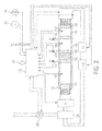
- Fig. 1 is a cut-away illustration of a thermoacoustic refrigerator including control circuitry for optimizing efficiency as a function of operating temperatures, ambient temperature and humidity, and selected user input according to a first embodiment of the present disclosure.
- Fig. 2 is a cut-away illustration of a thermoacoustic refrigerator including control circuitry for optimizing efficiency as a function of operating temperatures, ambient temperature and humidity, and selected user input according to a second embodiment of the present disclosure.
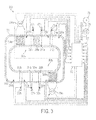
- Fig. 3 is a cut-away illustration of a thermoacoustic refrigerator including control circuitry for optimizing efficiency as a function of operating temperatures, ambient temperature and humidity, and selected user input according to a third embodiment of the present disclosure.
- Fig. 4 is a cut-away illustration of a thermoacoustic heat engine including control circuitry for optimizing efficiency as a function of operating temperatures, ambient temperature and humidity, and selected user input according to a first embodiment of the present disclosure.
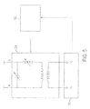
- Fig. 5 is a schematic illustration of a load control circuit of a type that may be deployed in a thermoacoustic heat engine of the type illustrated in Fig. 4 .
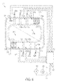
- Fig. 6 is a cut-away illustration of a thermoacoustic heat engine including control circuitry for optimizing efficiency as a function of operating temperatures, ambient temperature and humidity, and selected user input according to a second embodiment of the present disclosure.
- Fig. 7 is a schematic illustration of a power combiner circuit of a type that may be deployed in a thermoacoustic heat engine of the type illustrated in Fig. 4 .
- Fig. 1 is a cut-away illustration of a first embodiment of a thermoacoustic refrigerator 70 including control circuitry for optimizing efficiency as a function of operating temperatures, the ambient temperature and humidity, and selected user input. While Fig. 1 and the description associated therewith are focused on a refrigerator, it will be appreciated that the discussions herein apply equally to heat pumps, heat engines and other forms of thermoacoustic devices, particularly as described further herein.
- Thermoacoustic refrigerator 70 comprises a generally tubular body 72.
- the material from which body 72 is constructed may vary depending upon the application of the present invention. However, body 72 (and indeed all bodies described herein) should generally be thermally and acoustically insulative, and capable of withstanding pressurization to at least several atmospheres. Exemplary materials for body 72 include stainless steel or an iron-nickel-chromium alloy.
- regenerator 74 Disposed within body 72 is regenerator 74.
- Regenerator 74 (indeed, all regenerators described herein) may be constructed of any of a wide variety of materials and structural arrangements which provide a relatively high thermal mass and high surface area of interaction with the gas but low acoustic attenuation.
- a wire mesh or screen, open-cell material, random fiber mesh or screen, or other material and arrangement as will be understood by one skilled in the art may be employed.
- the density of the material comprising regenerator 74 may be constant, or may vary along its longitudinal axis such that the area of interaction between the gas and wall, and the acoustic impedance, across the longitudinal dimension of regenerator 74 may be tailored for optimal efficiency. Details of regenerator design are otherwise known in the art and are therefore not further discussed herein.
- Heat exchangers 76, 78 Adjacent each lateral end of regenerator 74 are first and second heat exchangers 76, 78, respectively.
- Heat exchangers 76, 78 may be constructed of any of a wide variety of materials and structural arrangements which provide a relatively high efficiency of heat transfer from within body 72 to a transfer medium.
- heat exchangers 76, 78 may be one or more tubes for carrying therein a fluid to be heated or cooled.
- Heat exchangers 76, 78 are formed of a material and sized and positioned to efficiently transfer thermal energy (heating or cooling) between the fluid therein and the gas within body 72 during operation of the refrigerator.
- heat exchangers 76, 78 may be increased with fins or other structures as is well known in the art. Tubes 77, 79 connected to heat exchangers 76, 78, respectively, permit the transfer of fluid from a thermal reservoir or load external to refrigerator 70 to and from heat exchangers 76, 78. Details of heat exchanger design are otherwise known in the art and are therefore not further discussed herein.
- a third heat exchanger 80 may be disposed within one end of body 72, for example such that heat exchanger 78 is located between third heat exchanger 80 and regenerator 74.
- Third heat exchanger 80 may be of a similar construction to first and second heat exchangers 76, 78 such as one or more tubes formed of a material and sized and positioned to efficiently transfer thermal energy (heating or cooling) between a fluid therein and the gas within body 72 during operation of the refrigerator.
- Tube 81 permits the transfer of fluid from a thermal reservoir or load external to refrigerator 70 to and from the third heat exchanger 80.
- An electromechanical driver 82 (for example an acoustic wave source) is disposed within body 72, proximate first heat exchanger 76.
- electromechanical driver 82 may serve the function of electromechanical driver 82, such as well-known moving coil, piezo-electric, electro-static, ribbon or other forms of loudspeaker.
- a very efficient, frequency tunable, and frequency stable speaker design is preferred so that the cooling efficiency of the refrigerator may be maximized.
- VFD variable frequency driver
- electromechanical driver 82 is connected to electromechanical driver 82.
- VFD 84 is capable of driving electromechanical driver 82 at a desired frequency and amplitude with very high conversion efficiency.
- An acoustic load 73 such as an orifice, forms a part of body 72 proximate second or third heat exchangers 78, 80, which dissipates acoustic energy.
- a gas such as helium
- Oscillating electric power from VFD 84 is provided to electromechanical driver 82 which generates acoustic oscillations in the gas.
- electromechanical driver 82 With proper choice of the dimensions and material choices for housing 72 and regenerator 74, and use of an appropriate gas, an approximate Stirling cycle is thus initiated in the region of regenerator 74, establishing a temperature gradient in regenerator 74 such that when the system reaches steady-state, first heat exchanger 76, the "hot” heat exchanger, is at relatively higher temperatures than second heat exchanger 78, the "cold" heat exchanger.
- a Stirling cycle comprises a constant-volume cooling of the gas as it moves in the direction from the hot heat exchanger to the cold heat exchanger, rejecting heat to the regenerator, isothermal expansion of the gas, constant-volume heating of the gas as it moves in the direction from the cold heat exchanger to the hot heat exchanger, accepting heat from the regenerator, and consequent isothermal contraction of the gas, at which point the gas is at its initial state and the process repeats itself. In this way heat is moved from the cold to the hot heat exchangers.
- Regenerator 74 serves to store heat energy and greatly improve the efficiency of energy conversion.
- VFD 84 drives electromechanical driver 82
- sensors are employed. These can be generally divided into two types; those that sense quantities largely independent of the operating state of the device, such as ambient temperature and humidity, and those that sense quantities that are somewhat or largely dependent on the operating state of the device, such as internal pressure amplitude, gas flow rate, gas temperatures, and heat exchanger temperatures, and the temperature of the space being cooled.
- thermocouples such as thermocouple 89 for measuring the temperature inside body 72 proximate heat exchanger 76, thermocouple 88 for measuring the temperature of the heat exchange fluid within heat exchanger 76, thermocouple 91 for measuring the temperature inside body 72 proximate heat exchanger 78, thermocouple 90 for measuring the temperature of the heat exchange fluid within heat exchanger 78, thermocouple 93 for measuring the temperature inside body 72 proximate heat exchanger 80, and thermocouple 92 for measuring the temperature of the heat exchange fluid within heat exchanger 80.
- thermocouples as temperature sensors is only illustrative; any type temperature sensor may be utilized.
- an ambient temperature sensor 94 such as a thermocouple, a thermometer, etc. is disposed proximate body 72 for measuring, for example the ambient temperature in the space to which heat is rejected by the refrigerator, in the space proximate an intake of the apparatus, the outside temperature, etc. That is, this space may be physically proximate thermoacoustic refrigerator 70 or physically remote from thermoacoustic refrigerator 70, such as outside of the building being cooled or in an adjacent room (in the case of thermoacoustic refrigerator 70 being a room cooler).
- temperature sensor 94 is proximate thermoacoustic refrigerator 70, in another it is for example in the room being cooled but not necessarily proximate thermoacoustic refrigerator 70, and in still another embodiment temperature sensor 94 need not be anywhere near thermoacoustic refrigerator 70.
- the ambient temperature and the temperature inside the space being cooled. The latter is dependent on the operation of the device (i.e., the device is cooling it) while the former isn't.
- the operation of thermoacoustic refrigerator 70 can therefore be in part a function of the "outside" temperature, and not just the temperature of the room being cooled.
- a hygrometer (humidity sensor) 96 may be disposed proximate body 72 for measuring the ambient humidity in the space to which heat is rejected by the refrigerator.
- Hygrometer 96, or additional hygrometers may also be located to measure the ambient absolute or relative humidity, as described above with regard to temperature sensor 94. It should be noted that while various thermocouples, a thermometer, and a hygrometer have been disclosed and shown in Fig. 1 , many of these elements are optional, and we suggest that the minimum embodiment comprise a single thermometer, thermocouple, or similar sensor 89.
- thermometer thermocouple, or similar sensor can measure temperature at a region of body 72, outside of the thermoacoustic device and in an area in which said thermoacoustic apparatus operates, at one of the heat exchangers, etc.
- additional thermocouples, thermometers, humidity sensors, and other sensors such as pressure and flow sensors, etc. may be provided, in various combinations, without departing the spirit and scope of the present disclosure.
- thermocouples 86, 88, 90, and 92, thermometer 94, and hygrometer 96 are connected to provide data signals to a controller 98.
- Controller 98 uses the various temperature, humidity, and other measurements to generate a control signal for controlling VFD 84, which controls (varies) the frequency and input power, current, and/or voltage of the electromechanical driver 82 to optimize efficiency or cooling power.
- Controller 98 may sample the various variables periodically during operation of thermoacoustic refrigerator 70 and may provide periodic updated control signals to VFD 84 to account for changes in operating and ambient conditions and thereby maintain an optimal or selected efficiency.
- controller 98 can generate control signals at least in part from a plurality of temperature data signals, the signal taken at various times during operation of the thermoacoustic refrigerator 70, such that operation of the electromechanical driver 82 based on the control signals provides optimized operational efficiency for said thermoacoustic refrigerator 70.
- other mechanisms may be provided such that the temperatures from thermocouples 86, 88, 90, and 92, thermometer 94, and hygrometer 96 (as well as other sensor devices) are provided to controller 98 at intervals during operation of thermoacoustic refrigerator 70.
- An additional input to controller 98 may be adjustable user parameters 99.
- Such user input parameters may include desired cooling power, maximum power consumption, desired cooling temperature, and so on for thermoacoustic refrigerator 70.
- controller 98 comprises logic that is programmed to vary the frequency and/or power of electromechanical transducer 82 according to a lookup table containing a mapping from ambient temperature to frequency and power. For example, the power can be left fixed and the frequency can be made to increase as the ambient temperature increases.
- the optimal frequency for 12.9 watts of input power was found to be 60 Hz.
- the controller can be implemented with an embedded microprocessor and analog-to-digital and digital-to-analog converters.
- a fully analog solution consisting of a VFD and combinations of transistor amplifiers and other electronic components can be used.
- a combination of analog and digital logic can be used.
- feedback control systems i.e., control systems using input variables dependent on the operating state of the device, and control systems with memory of the past state of the system, may achieve steady state operation only under certain conditions. Under other conditions, they may oscillate among different states, or fail to "capture” or "lock” into the desired state.
- control system may be designed to switch from utilizing solely independent variables to a combination of independent and dependent variables as the system nears its user-defined set point.
- some variables such as pressure amplitude
- others such as the temperature of the space being cooled
- the controller should respond to changes in the temperature of the space being cooled more slowly than to the changes in the pressure amplitude.
- This look-up table may not have entries for every combination of heat exchanger temperatures.
- the controller might have logic which would turn the refrigerator on at a certain default frequency and power until the temperatures reached a set in the look-up table, at which time the device would be set to be "locked” and the controller would begin to use the look-up table to define the operating parameters.
- controller 98 is designed for a specific thermoacoustic device (e.g., specific dimensions, materials, etc.)
- controller 98 is configurable for use with multiple devices.
- the lookup table can be stored in rewritable memory such as flash memory, and reprogrammed for each device. The lookup table need not be fixed for a given unit, but can be changed if the unit is moved to a different room, different conditions, etc.
- controllers can be interchangeable among devices of the same type (e.g., same cooling power), the controllers can be interchangeable among devices of different types (e.g., a 1 kW unit and a 10 kW unit), and/or an existing device can be retrofitted with sensors and a controller.
- controller 98 uses a feedback loop to optimize the efficiency and or power. Some sensed parameters, such as the outside temperature and humidity and the user settings, including the temperature set point, are independent of the controller output. Others, such as the internal temperatures of heat exchangers 76, 78, 80, the internal pressures, and the flow velocity, will vary as the frequency and power of VFD 84 are changed. Thus, in a feedback embodiment, additional sensors such as pressure and flow velocity sensors (not shown) located within body 72, and a measure of the state of VFD 84 (shown by the dashed line connecting VFD 84 and controller 98) are employed. A “feedback" system utilizes these latter values. A “feedforward” system only utilizes the former.
- the feedforward system will be universally stable while the feedback system may not. Accordingly, the control system with feedback may imply a more complex process. For example, in one embodiment the system starts up using only feedfarward-type (i.e., independent) inputs. Once the system reaches steady-state, the system then implements the feedback system.
- feedfarward-type i.e., independent
- Fig. 2 is a cut-away illustration of a second embodiment of a thermoacoustic refrigerator 100 including control circuitry for optimizing efficiency as a function of operating temperatures, the ambient temperature and humidity, and selected user input.
- Thermoacoustic refrigerator 100 comprises a generally tubular body 102. Disposed within body 102 is regenerator 104.
- Heat exchangers 106, 108 Adjacent each lateral end of regenerator 104 are first and second heat exchangers 106, 108, respectively.
- Heat exchangers 106, 108 may be constructed of any of a wide variety of materials and structural arrangements which provide a relatively high efficiency of heat transfer from within body 102 to a transfer medium.
- heat exchangers 106, 108 may be one or more tubes for carrying therein a fluid to be heated or cooled.
- Heat exchangers 106, 108 are formed of a material and sized and positioned to efficiently transfer thermal energy (heating or cooling) between the fluid therein and the gas within body 102 during operation of the refrigerator.
- the surface area of heat exchangers 106, 108 may be increased with fins or other structures as is well known in the art.
- Tubes 110, 112 permit the transfer of fluid from a thermal reservoir or load external to refrigerator 100 to and from heat exchangers 106, 108.
- a third heat exchanger 114 may be disposed within one end of body 102, for example such that heat exchanger 108 is located between third heat exchanger 114 and regenerator 104.
- Third heat exchanger 114 may be of a similar construction to first and second heat exchangers 106, 108 such as one or more tubes formed of a material and sized and positioned to efficiently transfer thermal energy (heating or cooling) between a fluid therein and the gas within body 102 during operation of the refrigerator.
- Tube 116 permits the transfer of fluid from a thermal reservoir or load external to refrigerator 100 to and from the third heat exchanger 114.
- An electromechanical driver 120 (for example an acoustic wave source) is disposed at a first longitudinal end of body 102, and an acoustic converter 122 is disposed at a second longitudinal end of body 102 opposite said electromechanical driver 120 relative to said regenerator 104.
- electromechanical driver 120 many different types of devices may serve the function of electromechanical driver 120, such as well-known moving coil, piezo-electric, electro-static, ribbon or other forms of loudspeaker.
- a very efficient, compact, frequency tunable, and frequency stable speaker design is preferred so that the cooling efficiency of the refrigerator may be maximized.
- acoustic converter 122 many different types may serve the function of acoustic converter 122.
- a well-known electrostatic, electromagnetic, piezo-electric or other form of microphone or pressure transducer may form acoustic converter 122.
- gas-spring, compliance elements, inertance elements, or other acoustic elements may also be employed to enhance the function of converter 122. Again, efficiency is a preferred attribute of acoustic converter 122 so that the cooling efficiency of the refrigerator may be maximized.
- VFD variable frequency driver
- a combiner 128 (of a type known in the art).
- VFD 126 is capable of driving electromechanical driver 120 at a desired frequency and amplitude with very high conversion efficiency.
- Outputs of combiner 128 form inputs to impedance circuit Z 1 .
- the outputs of impedance circuit Z 1 form the inputs to acoustic source 120.
- Outputs of a second impedance circuit Z 2 are connected as inputs to combiner 128.
- Outputs from acoustic converter 122 are provided as inputs to the impedance circuit Z 2 .
- phase delay circuit ⁇ ( ⁇ ) may also be employed to achieve the desired phasing as is well understood in the art.
- oscillating electric power from VFD 126 is provided to electromechanical driver 120, which generates acoustic oscillations in a gas, such as helium, sealed within housing 102.
- a gas such as helium
- regenerator 104 serves to store heat energy and greatly improve the efficiency of energy conversion.
- a number of sensing devices are employed (again, for sensing quantities largely independent of the operating state of the device, such as ambient temperature and humidity, and those that sense quantities that are somewhat or largely dependent on the operating state of the device, such as internal pressure amplitude and gas flow rate and heat exchanger temperatures, and the temperature of the space being cooled).
- the operating state of the device such as ambient temperature and humidity
- the sense quantities that are somewhat or largely dependent on the operating state of the device such as internal pressure amplitude and gas flow rate and heat exchanger temperatures, and the temperature of the space being cooled.
- the sensors are thermocouples, such as thermocouple 140 for measuring the temperature inside body 102 proximate first heat exchanger 106, thermocouple 142 for measuring the temperature of the heat exchange fluid within heat exchanger 106, thermocouple 144 for measuring the temperature of the heat exchange fluid within heat exchanger 108, thermocouple 145 for measuring the temperature inside body 102 proximate second heat exchanger 108, thermocouple 146 for measuring the temperature of the heat exchange fluid within heat exchanger 114, and thermocouple 147 for measuring the temperature inside body 102 proximate third heat exchanger 114.
- thermocouples for as temperature sensors is only illustrative; any type temperature sensor may be utilized.
- a temperature sensor 148 such as a thermometer or thermocouple is disposed for measuring the ambient temperature in the space to which heat is rejected by the refrigerator.
- a hygrometer (humidity sensor) 150 may be disposed for measuring the ambient humidity in the space to which heat is rejected by the refrigerator.
- thermocouples, a thermometer, and a hygrometer have been disclosed and shown in Fig. 1 , many of these elements are optional, and the minimum embodiment comprises a single thermocouple, thermometer or other sensor.
- additional thermocouples, thermometers, and other temperature-related sensors such as internal pressure sensors, etc. may be provided, in various combinations, without departing the spirit and scope of the present disclosure.
- thermocouples 104, 142, 144, and 146, thermometer 148, and hygrometer 150 are connected to provide data to a controller 152.
- Controller 152 uses the various temperature, humidity, and other measurements to generate a control signal for controlling VFD 126, which controls (varies) the frequency and input power, current, and/or voltage of the electromechanical driver 120 to optimize efficiency or cooling power.
- Controller 152 may also control the phase ( ⁇ (w) ) and impedances (Z 1 and Z 2 )
- An additional input to controller 152 may be adjustable user parameters 154.
- Such user input parameters may include desired cooling power, maximum power consumption, desired cooling temperature, and so on for thermoacoustic refrigerator 100.
- controller 152 comprises logic that is programmed to vary the frequency and/or power of electromechanical transducer 120 according to a lookup table containing a mapping from ambient temperature to frequency and power. For example, the power can be left fixed and the frequency can be made to increase as the ambient temperature increases.
- the lookup table can be implemented with an embedded microprocessor and analog-to-digital and digital-to-analog converters.
- a fully analog solution consisting of a VFD and combinations of transistor amplifiers and other electronic components can be used.
- a combination of analog and digital logic can be used.
- thermoacoustic device to thermoacoustic device. They will also differ depending on user preferences, such as cooling power.
- a user may be provided with control over various inputs 154 to controller 152, for example via a software interface (not shown).
- additional sensors such as pressure and flow velocity sensors (not shown) located within body 102, a measure of the state of VFD 126, and/or a measure of the output of converter 122 are employed.
- FIG. 3 illustrates one example of such an alternative.
- Thermoacoustic refrigerator 200 illustrated in Fig. 3 is a closed loop apparatus with series-connected cooling stages.
- such a system comprises two or more cooling stages 202a, 202b each including an electromechanical driver 204a, 204b, first heat exchanger 206a, 206b, regenerator 208a, 208b, second heat exchanger 210a, 210b, and optional third heat exchanger 212a, 212b, essentially arranged as described above.
- Each stage 202a, 202b further comprises an acoustic transmission line 214a, 214b (which in one embodiment are channels through which an acoustic wave may travel), connected to the back side of the electromechanical driver of the next state in series.
- thermocouples 222a, 224a, and 226a are provided for measuring the temperatures of the heat exchange fluid within heat exchangers 206a, 210a, and 212a, respectively.
- Thermocouples 221a, 223a, and 225a are provided for measuring the temperatures proximate heat exchangers 206a, 210a, and 212a, respectively.
- thermocouples 222b, 224b, and 226b are provided for measuring the temperatures of the heat exchange fluid within heat exchangers 206b, 210b, and 212b, respectively.
- thermocouples 221b, 223b, and 225b are provided for measuring the temperatures proximate heat exchangers 206b, 210b, and 212b, respectively.
- thermometer 228 is disposed for measuring the ambient temperature in the space to which heat is rejected by the refrigerator.
- a hygrometer (humidity sensor) 230 may be disposed for measuring the ambient humidity in the space to which heat is rejected by the refrigerator.
- thermocouples, thermometer 228, and hygrometer 230 provide data to a controller 232.
- Controller 232 uses the various temperature, humidity, and other measurements to generate a control signal for controlling VFDs 234a, 234b, which control (vary) the frequencies, relative phases, and input power, current, and/or voltage provided to electromechanical drivers 204a, 204b, and/or relative phases of the current and/or voltage of the drivers, to optimize efficiency or cooling power.
- controller 232 is capable of independently controlling VFDs 234a, 234b, thereby compensating for differences in the material, dimensions, locations, and other variables between stages 202a, 202b.
- An additional input to controller 232 may be adjustable user parameters 236.
- Such user input parameters may include desired cooling power, maximum power consumption, desired cooling temperature, and so on for thermoacoustic refrigerator 200.
- controller 232 comprises logic that is programmed (and optionally, reprogrammable) to vary the frequency and/or power and/or current phase of electromechanical transducers 204a, 204b according to a lookup table containing a mapping from temperatures to frequency, power, and phase for each stage.
- a fully analog solution consisting of a VFD and combinations of transistor amplifiers and other electronic components for each stage 202a, 202b can be used.
- a combination of analog and digital logic can be used.
- controller 232 Additional, optional inputs to controller 232 are feedback from VFDs 234a, 234b, and data from additional sensors such as pressure and flow velocity sensors (not shown) located within body 201.
- the feedback loop may be used to further optimize the efficiency and or power use of thermoacoustic refrigerator 200 and provide operational stability as previously discussed.
- thermoacoustic heat engine 300 is a cross-sectional representation of one embodiment of thermoacoustic heat engine 300 incorporating these general principles.
- Many elements of thermoacoustic heat engine 300 are well known, but briefly, it comprises a hollow, looped, sealed body structure 302 having a regenerator 304 located therein.
- the regenerator is proximate first heat exchanger 306, generally a "cold" exchanger, at a first end thereof and a second heat exchanger 308, generally a "hot” exchanger, at the opposite end thereof.
- a third heat exchanger 310 generally at ambient temperature, may optionally be present.
- a resonator 312, in the form of an extension of the hollow body structure 302, is provided.
- Body structure 302 is filled with a pressurized gas.
- a temperature differential is induced across regenerator 304, i.e., between cold heat exchanger 306 and hot heat exchanger 308, subjecting the gas to localized heat transfer.
- Acoustic energy in the form of a pressure wave in the region of the regenerator subjects the gas to local periodic compression and expansion. Under favorable acoustic conditions, the gas effectively undergoes an approximate Stirling cycle in regenerator 304.
- thermoacoustic heat engines use an acoustic resonator and/or an acoustic feedback network 314 to achieve this large impedance.
- a network is not adjustable in use, and does not take into account operating conditions of the heat engine in order to optimize operation.
- thermoacoustic heat engine 300 provided with a variable acoustic impedance, such as an electromechanical transducer 316, which may provide impedance tuning (load) in order to optimize efficiency and operation of thermoacoustic heat engine 300, for example, by modifying the resonant frequency of the device.
- a controllable portion of the energy of the pressure wave within body 302 may be converted to electrical energy by electromechanical transducer 316, depending on various system and ambient temperatures and operating conditions.
- thermocouples 322, 324, and 326 for measuring the temperature of the heat exchange fluid within heat exchangers 306, 308, and 310, respectively.
- thermocouples 321, 323, and 325 are provided for measuring the temperatures within body 302 proximate heat exchangers 306, 308, and 310, respectively.
- thermometer 328 is disposed proximate body 302 for measuring the ambient temperature in the space to which heat is rejected by the heat engine.
- a hygrometer (humidity sensor) 330 may be disposed proximate body 302 for measuring the ambient humidity in the space to which heat is rejected by the heat engine.
- thermocouples, thermometer 328, and hygrometer 330 are connect to provide data to a controller 332.
- Controller 232 uses the various temperature, humidity, and other measurements to generate a control signal for controlling a load control circuit 324, described in further detail below, which is connected to electromechanical transducer 316.
- Load control circuit 324 controls (varies) the load presented by electromechanical transducer 316 and hence tunes the impedance within thermoacoustic heat engine 300 to optimize efficiency of heating.
- An additional input to controller 332 may be adjustable user parameters 336.
- Such user input parameters may include desired heating, efficiency factor, and so on for thermoacoustic heat engine 300.
- controller 332 comprises logic that is programmed (and optionally, reprogrammable) to control load control circuit 334 according to a lookup table containing a mapping from temperatures to load.
- a lookup table containing a mapping from temperatures to load.
- an analog solution consisting of load control circuit 334 and a combination of transistor amplifiers and other electronic components can be used.
- a combination of analog and digital logic can be used.
- Fig. 5 illustrates one example of a load control circuit 334 of a type that may be employed in the thermoacoustic heat engine 300 of Fig. 4 .
- a form of variable tap transformer circuit under control of controller 332, is shown.
- Electromechanical transducer 316 is connected at s n , t n , to load control circuit 334.
- At least a portion of the power attenuated by electromechanical transducer 316 is available for use at the output of load control circuit 334 at u n , v n , and a system 350 to which u n , v n are connected will in part dictate the impedance of electromechanical transducer 316.
- a feedback signal is provided from system 350 back to controller 332 in order that controller 332 may provide an optimized control signal to load control circuit 334.
- FIG. 6 illustrates one example of such an alternative, in this case a two-stage looped heat engine 500.
- a system comprises a housing 502, divided roughly into two heating stages 504a, 504b (although more than two stages is within the scope of this disclosure).
- first heat exchangers 506a, 506b Disposed in each stage 504a, 504b are first heat exchangers 506a, 506b, regenerators 508a, 508b, second heat exchangers 510a, 510b, and optional third heat exchangers 512a, 512b, positioned and operated consistent with the description above.
- electromechanical transducers 514a, 514b are disposed within each stage.
- Each stage 504a, 504b further comprises an acoustic transmission line 516a, 516b (which in one embodiment are each a channel through which an acoustic wave may travel), connected to the back side of the electromechanical transducer of the next state in series.
- an acoustic transmission line 516a, 516b (which in one embodiment are each a channel through which an acoustic wave may travel), connected to the back side of the electromechanical transducer of the next state in series.
- thermocouples 520a, 520b for measuring the temperature of the heat exchange fluid within heat exchangers 506a, 506b, respectively; thermocouples 522a, 522b for measuring the temperature of the heat exchange fluid within heat exchangers 510a, 510b, respectively; and optionally, thermocouples 524a, 524b for measuring the temperature of the heat exchange fluid within heat exchangers 512a, 512b, respectively.
- thermocouples 519a, 521 a, and 523a are provided for measuring the temperature inside body 501 proximate heat exchangers 506a, 510a, and 512a, respectively.
- thermocouples 519b, 521b, and 523b are provided for measuring the temperature inside body 501 proximate heat exchangers 506b, 510b, and 512b, respectively.
- Thermometer 528 is disposed proximate thermoacoustic refrigerator 500 for measuring the ambient temperature in the space to which heat is rejected by the heat engine.
- a hygrometer (humidity sensor) 530 may be disposed proximate thermoacoustic refrigerator 500 for measuring the ambient humidity in the space to which heat is rejected by the heat engine.
- thermocouples, thermometer 528, and hygrometer 530 are connect to provide data to a controller 532.
- Controller 532 uses the various temperature, humidity, and other measurements to generate a control signal for controlling load control circuits (not shown) connected to taps s, t of electromechanical transducers 514a, 514b, respectively, It should be noted that controller 532 is capable of independently controlling each load control circuit for independent load adjustment of electromechanical transducers 514a, 514b, thereby compensating for differences in the material, dimensions, locations, and other variables between stages 504a, 504b.
- An additional input to controller 532 may be adjustable user parameters 534.
- Such user input parameters may include desired heat consumption, output power, and so on for thermoacoustic heat engine 500.
- controller 532 comprises logic that is programmed (and optionally, reprogrammable) to control load control circuits for electromechanical transducers 514a, 514b according to a lookup table containing a mapping from temperatures to load for each stage.
- controller 532 comprises logic that is programmed (and optionally, reprogrammable) to control load control circuits for electromechanical transducers 514a, 514b according to a lookup table containing a mapping from temperatures to load for each stage.
- an analog solution consisting of load control circuits and a combination of transistor amplifiers and other electronic components can be used.
- a combination of analog and digital logic can be used.
- electromechanical transducers 514a, 514b may be used to perform useful work.
- electromechanical transducers 514a, 514b there may be as many as n electromechanical transducers providing this power.
- the outputs from these electromechanical transducers may be combined in a combiner circuit 352 shown in Fig. 7 to provide a single output pair x, y for connection to a system (not shown) for performing work.
- the system to which x and y are connected will in part dictate the frequency and impedance of electromechanical transducers in the n-stage heat engine.
- a feedback signal is provided from that system back to a controller (such as controller 532 of Fig. 6 ) in order that an optimized control signal may be provided to the various load control circuits (such as load control circuit 334 of Fig. 5 ).
- thermocouples have been described as devices employed for measuring the temperatures of various parts of the thermoacoustic apparatus during use, other temperature sensors such as thermistors, thermal/infrared imaging sensors, etc. may similarly be employed.
- thermocouples have been described as devices employed for measuring the temperatures of various parts of the thermoacoustic apparatus during use, other temperature sensors such as thermistors, thermal/infrared imaging sensors, etc. may similarly be employed.
- various of the above-disclosed and other features and functions, or alternative thereof may be desirably combined into many other different systems or applications.
Landscapes
- Engineering & Computer Science (AREA)
- Physics & Mathematics (AREA)
- Mechanical Engineering (AREA)
- Thermal Sciences (AREA)
- General Engineering & Computer Science (AREA)
- Power Engineering (AREA)
- Devices That Are Associated With Refrigeration Equipment (AREA)
- Feedback Control In General (AREA)
Applications Claiming Priority (1)
| Application Number | Priority Date | Filing Date | Title |
|---|---|---|---|
| US12/771,666 US8375729B2 (en) | 2010-04-30 | 2010-04-30 | Optimization of a thermoacoustic apparatus based on operating conditions and selected user input |
Publications (3)
| Publication Number | Publication Date |
|---|---|
| EP2383530A2 true EP2383530A2 (de) | 2011-11-02 |
| EP2383530A3 EP2383530A3 (de) | 2013-02-20 |
| EP2383530B1 EP2383530B1 (de) | 2019-11-27 |
Family
ID=44483972
Family Applications (1)
| Application Number | Title | Priority Date | Filing Date |
|---|---|---|---|
| EP11162925.9A Active EP2383530B1 (de) | 2010-04-30 | 2011-04-19 | Optimierung einer thermoakustischen Vorrichtung basierend auf Betriebsbedingungen und ausgewählter Benutzereingabe |
Country Status (5)
| Country | Link |
|---|---|
| US (1) | US8375729B2 (de) |
| EP (1) | EP2383530B1 (de) |
| JP (1) | JP5771054B2 (de) |
| KR (1) | KR101702140B1 (de) |
| TW (1) | TWI468633B (de) |
Cited By (3)
| Publication number | Priority date | Publication date | Assignee | Title |
|---|---|---|---|---|
| CN103808063A (zh) * | 2014-02-14 | 2014-05-21 | 中国科学院理化技术研究所 | 一种声学共振型热驱动行波热声制冷系统 |
| EP2874292A1 (de) * | 2013-11-18 | 2015-05-20 | Société Technique pour l'Energie Atomique | Thermoakustischer magnetohydrodynamischer Elektrogenerator |
| CN104653330A (zh) * | 2013-11-22 | 2015-05-27 | 同济大学 | 一种冷源脉管发动机和基于冷源脉管发动机的发电装置 |
Families Citing this family (21)
| Publication number | Priority date | Publication date | Assignee | Title |
|---|---|---|---|---|
| US8227928B2 (en) * | 2009-07-31 | 2012-07-24 | Palo Alto Research Center Incorporated | Thermo-electro-acoustic engine and method of using same |
| CN102734975B (zh) * | 2011-04-01 | 2014-04-02 | 中科力函(深圳)热声技术有限公司 | 一种双作用热驱动行波热声制冷系统 |
| US8991170B2 (en) * | 2011-05-01 | 2015-03-31 | Thomas Mallory Sherlock | Solar air conditioning heat pump with minimized dead volume |
| US9163581B2 (en) * | 2012-02-23 | 2015-10-20 | The United States Of America As Represented By The Administrator Of National Aeronautics And Space Administration | Alpha-stream convertor |
| JP2015519727A (ja) * | 2012-04-03 | 2015-07-09 | シーメンス アクチエンゲゼルシヤフトSiemens Aktiengesellschaft | 冷却装置 |
| US20150153100A1 (en) * | 2013-12-04 | 2015-06-04 | General Electric Company | System and method for hybrid refrigeration gas liquefaction |
| CN103758657B (zh) * | 2014-01-21 | 2015-05-06 | 中国科学院理化技术研究所 | 一种声学共振型行波热声发电系统 |
| US20160007773A1 (en) * | 2014-07-14 | 2016-01-14 | Eric W. Renshaw | Cooling blanket with cooling capability |
| US10156185B2 (en) | 2014-11-24 | 2018-12-18 | Nirvana Energy Systems, Inc. | Secure control system for multistage thermo acoustic micro-CHP generator |
| JP6495098B2 (ja) * | 2015-05-21 | 2019-04-03 | 中央精機株式会社 | 熱音響発電システム |
| JP6495097B2 (ja) * | 2015-05-21 | 2019-04-03 | 中央精機株式会社 | 熱音響発電システム |
| CN104848586A (zh) * | 2015-05-28 | 2015-08-19 | 武汉化院科技有限公司 | 一种声波驱动式温度调控装置 |
| US9841009B2 (en) * | 2015-07-28 | 2017-12-12 | Northrop Grumman Systems Corporation | Hybrid power system |
| US10227950B1 (en) * | 2016-02-05 | 2019-03-12 | The United States Of America As Represented By The Administrator Of National Aeronautics And Space Administration | Thermoacoustic convertor |
| JP6534358B2 (ja) * | 2016-03-22 | 2019-06-26 | 住友重機械工業株式会社 | クライオポンプ、クライオポンプ制御装置及びクライオポンプ制御方法 |
| JP6632029B2 (ja) * | 2016-06-09 | 2020-01-15 | 中央精機株式会社 | 熱音響エンジン、及び、熱音響エンジンの設計方法 |
| CN109541938B (zh) * | 2017-09-22 | 2022-01-28 | 中国科学院理化技术研究所 | 一种自适应有源前馈控制的双声源驱动热声系统 |
| SI25712A (sl) * | 2018-09-04 | 2020-03-31 | Gorenje Gospodinjski Aparati, D.O.O. | Metoda prenosa toplote v združeni strukturi toplotnega regeneratorja in izvedba toplotnega regeneratorja |
| JP7292631B2 (ja) * | 2019-05-09 | 2023-06-19 | 株式会社ジェイテクト | 熱音響装置 |
| JP7542852B2 (ja) * | 2020-10-15 | 2024-09-02 | 学校法人東海大学 | 熱音響システム、熱音響システムの制御方法、及び熱音響システムの調整方法 |
| US12411951B2 (en) * | 2022-12-22 | 2025-09-09 | Xerox Corporation | System and method for security control in cyber-physical systems with delay-induced feedback watermarking |
Family Cites Families (62)
| Publication number | Priority date | Publication date | Assignee | Title |
|---|---|---|---|---|
| GB1252258A (de) | 1968-01-19 | 1971-11-03 | ||
| US3548589A (en) | 1968-01-19 | 1970-12-22 | Atomic Energy Authority Uk | Heat engines |
| US4114380A (en) | 1977-03-03 | 1978-09-19 | Peter Hutson Ceperley | Traveling wave heat engine |
| US4355517A (en) | 1980-11-04 | 1982-10-26 | Ceperley Peter H | Resonant travelling wave heat engine |
| US4398398A (en) | 1981-08-14 | 1983-08-16 | Wheatley John C | Acoustical heat pumping engine |
| US4489553A (en) | 1981-08-14 | 1984-12-25 | The United States Of America As Represented By The United States Department Of Energy | Intrinsically irreversible heat engine |
| US4389849A (en) | 1981-10-02 | 1983-06-28 | Beggs James M Administrator Of | Stirling cycle cryogenic cooler |
| US4534176A (en) | 1984-03-23 | 1985-08-13 | The United States Of America As Represented By The Secretary Of The Army | Linear resonance cryogenic cooler |
| US4686407A (en) | 1986-08-01 | 1987-08-11 | Ceperley Peter H | Split mode traveling wave ring-resonator |
| US5357757A (en) | 1988-10-11 | 1994-10-25 | Macrosonix Corp. | Compression-evaporation cooling system having standing wave compressor |
| US5167124A (en) | 1988-10-11 | 1992-12-01 | Sonic Compressor Systems, Inc. | Compression-evaporation cooling system having standing wave compressor |
| US5369625A (en) | 1991-05-31 | 1994-11-29 | The United States Of America As Represented By The Secretary Of The Navy | Thermoacoustic sound generator |
| US5329768A (en) | 1991-06-18 | 1994-07-19 | Gordon A. Wilkins, Trustee | Magnoelectric resonance engine |
| US5303555A (en) | 1992-10-29 | 1994-04-19 | International Business Machines Corp. | Electronics package with improved thermal management by thermoacoustic heat pumping |
| US5647216A (en) | 1995-07-31 | 1997-07-15 | The United States Of America As Represented By The Secretary Of The Navy | High-power thermoacoustic refrigerator |
| US5673561A (en) | 1996-08-12 | 1997-10-07 | The Regents Of The University Of California | Thermoacoustic refrigerator |
| NL1007316C1 (nl) | 1997-10-20 | 1999-04-21 | Aster Thermo Akoestische Syste | Thermo-akoestisch systeem. |
| US6032464A (en) * | 1999-01-20 | 2000-03-07 | Regents Of The University Of California | Traveling-wave device with mass flux suppression |
| US6385972B1 (en) | 1999-08-30 | 2002-05-14 | Oscar Lee Fellows | Thermoacoustic resonator |
| US6622470B2 (en) | 2000-05-12 | 2003-09-23 | Clean Energy Systems, Inc. | Semi-closed brayton cycle gas turbine power systems |
| JP3396732B2 (ja) * | 2000-08-15 | 2003-04-14 | 独立行政法人産業技術総合研究所 | パルス管冷凍機の制御方法 |
| JP4441091B2 (ja) | 2000-10-16 | 2010-03-31 | 本田技研工業株式会社 | 内燃機関の排気熱エネルギ回収装置 |
| JP2002228287A (ja) * | 2001-01-31 | 2002-08-14 | Daikin Ind Ltd | パルス管冷凍機 |
| US6578364B2 (en) | 2001-04-20 | 2003-06-17 | Clever Fellows Innovation Consortium, Inc. | Mechanical resonator and method for thermoacoustic systems |
| US6574968B1 (en) | 2001-07-02 | 2003-06-10 | University Of Utah | High frequency thermoacoustic refrigerator |
| US7240495B2 (en) | 2001-07-02 | 2007-07-10 | University Of Utah Research Foundation | High frequency thermoacoustic refrigerator |
| BRPI0103786B1 (pt) * | 2001-08-29 | 2015-06-16 | Brasil Compressores Sa | Sistema de controle de refrigeração de um ambiente refrigerado, método de controle de um sistema de refrigeração e refrigerador |
| US6591610B2 (en) | 2001-11-26 | 2003-07-15 | Sony Corporation | Converting dissipated heat to work energy using a thermo-acoustic generator |
| US6688112B2 (en) | 2001-12-04 | 2004-02-10 | University Of Mississippi | Thermoacoustic refrigeration device and method |
| AU2003225812A1 (en) | 2002-03-13 | 2003-09-29 | Georgia Tech Research Corporation | Travelling-wave thermoacoustic engines with internal combustion and associated methods |
| US6732515B1 (en) | 2002-03-13 | 2004-05-11 | Georgia Tech Research Corporation | Traveling-wave thermoacoustic engines with internal combustion |
| US6711905B2 (en) | 2002-04-05 | 2004-03-30 | Lockheed Martin Corporation | Acoustically isolated heat exchanger for thermoacoustic engine |
| US6725670B2 (en) | 2002-04-10 | 2004-04-27 | The Penn State Research Foundation | Thermoacoustic device |
| US7290771B2 (en) | 2002-04-10 | 2007-11-06 | The Penn State Research Foundation | Bellows seals for thermoacoustic devices and reciprocating machinery |
| US6792764B2 (en) | 2002-04-10 | 2004-09-21 | The Penn State Research Foundation | Compliant enclosure for thermoacoustic device |
| US6658862B2 (en) | 2002-04-18 | 2003-12-09 | The Regents Of The University Of California | Cascaded thermoacoustic devices |
| US6666033B1 (en) | 2002-06-06 | 2003-12-23 | The Regents Of The University Of California | Method and apparatus for fine tuning an orifice pulse tube refrigerator |
| US6560970B1 (en) | 2002-06-06 | 2003-05-13 | The Regents Of The University Of California | Oscillating side-branch enhancements of thermoacoustic heat exchangers |
| US6644028B1 (en) | 2002-06-20 | 2003-11-11 | The Regents Of The University Of California | Method and apparatus for rapid stopping and starting of a thermoacoustic engine |
| US6910332B2 (en) | 2002-10-15 | 2005-06-28 | Oscar Lee Fellows | Thermoacoustic engine-generator |
| US7017351B2 (en) | 2002-11-21 | 2006-03-28 | Mems Optical, Inc. | Miniature thermoacoustic cooler |
| US6604364B1 (en) | 2002-11-22 | 2003-08-12 | Praxair Technology, Inc. | Thermoacoustic cogeneration system |
| US7062921B2 (en) | 2002-12-30 | 2006-06-20 | Industrial Technology Research Institute | Multi-stage thermoacoustic device |
| WO2004088218A1 (en) | 2003-03-25 | 2004-10-14 | Utah State University | Thermoacoustic cooling device |
| AU2003229755A1 (en) * | 2003-03-31 | 2004-10-25 | Sap Aktiengesellschaft | A method and a computer system for scheduling processes in process chains |
| US7081699B2 (en) | 2003-03-31 | 2006-07-25 | The Penn State Research Foundation | Thermoacoustic piezoelectric generator |
| NL1023759C1 (nl) | 2003-06-27 | 2004-12-28 | Cornelis Maria De Blok | Meertraps brander aangedreven thermoakoestische warmtemotor. |
| JP4146770B2 (ja) * | 2003-08-11 | 2008-09-10 | 中部電力株式会社 | 電力貯蔵装置 |
| TWI226307B (en) | 2003-08-26 | 2005-01-11 | Ind Tech Res Inst | Thermo-acoustic microfluid driving device |
| JP2005188841A (ja) * | 2003-12-25 | 2005-07-14 | Toyota Motor Corp | 熱音響エンジンおよび熱音響冷凍機 |
| JP2005345023A (ja) * | 2004-06-03 | 2005-12-15 | Toyota Motor Corp | 熱音響エンジン |
| CN101133232B (zh) * | 2004-12-03 | 2012-11-07 | 哈里伯顿能源服务公司 | 井底操作中的加热和冷却电气元件 |
| JP4652822B2 (ja) | 2005-01-07 | 2011-03-16 | 学校法人同志社 | 熱音響装置 |
| JP4554374B2 (ja) | 2005-01-07 | 2010-09-29 | 学校法人同志社 | 熱交換器、及び、その熱交換器を用いた熱音響装置 |
| TWI285630B (en) | 2005-05-05 | 2007-08-21 | Lee Chih Kung | Passive thermoacoustic cooling apparatus |
| US20060266041A1 (en) | 2005-05-24 | 2006-11-30 | Fellows Oscar L | Thermoacoustic Thermomagnetic Generator |
| US7434409B2 (en) | 2005-08-23 | 2008-10-14 | Sunpower, Inc. | Pulse tube cooler having ¼ wavelength resonator tube instead of reservoir |
| JP2007147192A (ja) * | 2005-11-29 | 2007-06-14 | Sumitomo Heavy Ind Ltd | 熱音響冷凍機 |
| US7614240B2 (en) * | 2006-09-22 | 2009-11-10 | Praxair Technology, Inc. | Control method for pulse tube cryocooler |
| JP2008286507A (ja) * | 2007-05-21 | 2008-11-27 | Sumitomo Heavy Ind Ltd | パルス管冷凍機 |
| US8468838B2 (en) | 2008-04-01 | 2013-06-25 | Los Alamos National Security, Llc | Thermoacoustic refrigerators and engines comprising cascading stirling thermodynamic units |
| WO2010107308A1 (en) | 2009-02-25 | 2010-09-23 | Cornelis Maria De Blok | Multistage traveling wave thermoacoustic engine with phase distributed power extraction |
-
2010
- 2010-04-30 US US12/771,666 patent/US8375729B2/en not_active Expired - Fee Related
-
2011
- 2011-04-14 JP JP2011090188A patent/JP5771054B2/ja active Active
- 2011-04-19 EP EP11162925.9A patent/EP2383530B1/de active Active
- 2011-04-28 TW TW100114860A patent/TWI468633B/zh not_active IP Right Cessation
- 2011-05-02 KR KR1020110041619A patent/KR101702140B1/ko not_active Expired - Fee Related
Non-Patent Citations (1)
| Title |
|---|
| None |
Cited By (6)
| Publication number | Priority date | Publication date | Assignee | Title |
|---|---|---|---|---|
| EP2874292A1 (de) * | 2013-11-18 | 2015-05-20 | Société Technique pour l'Energie Atomique | Thermoakustischer magnetohydrodynamischer Elektrogenerator |
| WO2015071485A1 (en) * | 2013-11-18 | 2015-05-21 | Societe Technique Pour L'energie Atomique | Thermoacoustic magnetohydrodynamic electric generator |
| CN104653330A (zh) * | 2013-11-22 | 2015-05-27 | 同济大学 | 一种冷源脉管发动机和基于冷源脉管发动机的发电装置 |
| CN104653330B (zh) * | 2013-11-22 | 2016-03-02 | 同济大学 | 一种冷源脉管发动机和基于冷源脉管发动机的发电装置 |
| CN103808063A (zh) * | 2014-02-14 | 2014-05-21 | 中国科学院理化技术研究所 | 一种声学共振型热驱动行波热声制冷系统 |
| CN103808063B (zh) * | 2014-02-14 | 2016-02-03 | 中国科学院理化技术研究所 | 一种声学共振型热驱动行波热声制冷系统 |
Also Published As
| Publication number | Publication date |
|---|---|
| JP5771054B2 (ja) | 2015-08-26 |
| TWI468633B (zh) | 2015-01-11 |
| EP2383530A3 (de) | 2013-02-20 |
| US20110265505A1 (en) | 2011-11-03 |
| US8375729B2 (en) | 2013-02-19 |
| KR20110121593A (ko) | 2011-11-07 |
| TW201217730A (en) | 2012-05-01 |
| EP2383530B1 (de) | 2019-11-27 |
| JP2011237165A (ja) | 2011-11-24 |
| KR101702140B1 (ko) | 2017-02-03 |
Similar Documents
| Publication | Publication Date | Title |
|---|---|---|
| EP2383530B1 (de) | Optimierung einer thermoakustischen Vorrichtung basierend auf Betriebsbedingungen und ausgewählter Benutzereingabe | |
| EP1025401B1 (de) | Thermo-akustische anlage | |
| WO2008036920A2 (en) | Control method for pulse tube cryocooler | |
| US6032464A (en) | Traveling-wave device with mass flux suppression | |
| US20110265493A1 (en) | Thermoacoustic Apparatus With Series-Connected Stages | |
| JP5570899B2 (ja) | 熱電気音響エンジン及びその使用方法 | |
| JP4362632B2 (ja) | パルス管冷凍機 | |
| US6622491B2 (en) | Periodically operating refrigeration machine | |
| WO2003104725A1 (en) | Method and apparatus for fine tuning an orifice pulse tube refrigerator | |
| US20090084116A1 (en) | Gas phase shifting multistage displacer cryocooler | |
| US5867991A (en) | Ferroelectric Stirling-cycle refrigerator | |
| US20250207824A1 (en) | Cryocooling system | |
| JP2006118728A (ja) | 熱音響冷凍機 | |
| Duband et al. | Experimental results on inertance and permanent flow in pulse tube coolers | |
| JP2004301445A (ja) | パルス管冷凍機 | |
| JP2815031B2 (ja) | 冷凍装置 | |
| Yang et al. | Medium-size pulse tube coolers with linear compressor | |
| Thummes et al. | Development of Stirling-type pulse tube coolers driven by commercial linear compressors | |
| CN113237246B (zh) | 一种斯特林制冷制热一体机 | |
| JPH10185340A (ja) | パルス管式冷凍機 | |
| NL2007434C2 (en) | Thermo-acoustic system. | |
| Rajavel et al. | Design and Fabrication of Thermo Acoustic Refrigeration System | |
| Jalink Jr et al. | Ferroelectric Stirling-Cycle Refrigerator | |
| Yap et al. | Design and Construction of a Simple Standing Wave Thermoacoustic Refrigerator | |
| Aerts et al. | Comparison of the orifice, inertance and double inlet pulse tube refrigerator |
Legal Events
| Date | Code | Title | Description |
|---|---|---|---|
| AK | Designated contracting states |
Kind code of ref document: A2 Designated state(s): AL AT BE BG CH CY CZ DE DK EE ES FI FR GB GR HR HU IE IS IT LI LT LU LV MC MK MT NL NO PL PT RO RS SE SI SK SM TR |
|
| AX | Request for extension of the european patent |
Extension state: BA ME |
|
| PUAI | Public reference made under article 153(3) epc to a published international application that has entered the european phase |
Free format text: ORIGINAL CODE: 0009012 |
|
| PUAL | Search report despatched |
Free format text: ORIGINAL CODE: 0009013 |
|
| AK | Designated contracting states |
Kind code of ref document: A3 Designated state(s): AL AT BE BG CH CY CZ DE DK EE ES FI FR GB GR HR HU IE IS IT LI LT LU LV MC MK MT NL NO PL PT RO RS SE SI SK SM TR |
|
| AX | Request for extension of the european patent |
Extension state: BA ME |
|
| RIC1 | Information provided on ipc code assigned before grant |
Ipc: F25B 9/14 20060101AFI20130117BHEP |
|
| 17P | Request for examination filed |
Effective date: 20130820 |
|
| RBV | Designated contracting states (corrected) |
Designated state(s): AL AT BE BG CH CY CZ DE DK EE ES FI FR GB GR HR HU IE IS IT LI LT LU LV MC MK MT NL NO PL PT RO RS SE SI SK SM TR |
|
| STAA | Information on the status of an ep patent application or granted ep patent |
Free format text: STATUS: EXAMINATION IS IN PROGRESS |
|
| 17Q | First examination report despatched |
Effective date: 20180315 |
|
| GRAP | Despatch of communication of intention to grant a patent |
Free format text: ORIGINAL CODE: EPIDOSNIGR1 |
|
| STAA | Information on the status of an ep patent application or granted ep patent |
Free format text: STATUS: GRANT OF PATENT IS INTENDED |
|
| INTG | Intention to grant announced |
Effective date: 20190624 |
|
| GRAS | Grant fee paid |
Free format text: ORIGINAL CODE: EPIDOSNIGR3 |
|
| GRAA | (expected) grant |
Free format text: ORIGINAL CODE: 0009210 |
|
| STAA | Information on the status of an ep patent application or granted ep patent |
Free format text: STATUS: THE PATENT HAS BEEN GRANTED |
|
| AK | Designated contracting states |
Kind code of ref document: B1 Designated state(s): AL AT BE BG CH CY CZ DE DK EE ES FI FR GB GR HR HU IE IS IT LI LT LU LV MC MK MT NL NO PL PT RO RS SE SI SK SM TR |
|
| REG | Reference to a national code |
Ref country code: GB Ref legal event code: FG4D |
|
| REG | Reference to a national code |
Ref country code: CH Ref legal event code: EP |
|
| REG | Reference to a national code |
Ref country code: DE Ref legal event code: R096 Ref document number: 602011063598 Country of ref document: DE |
|
| REG | Reference to a national code |
Ref country code: AT Ref legal event code: REF Ref document number: 1207122 Country of ref document: AT Kind code of ref document: T Effective date: 20191215 |
|
| REG | Reference to a national code |
Ref country code: IE Ref legal event code: FG4D |
|
| REG | Reference to a national code |
Ref country code: NL Ref legal event code: MP Effective date: 20191127 |
|
| REG | Reference to a national code |
Ref country code: LT Ref legal event code: MG4D |
|
| PG25 | Lapsed in a contracting state [announced via postgrant information from national office to epo] |
Ref country code: GR Free format text: LAPSE BECAUSE OF FAILURE TO SUBMIT A TRANSLATION OF THE DESCRIPTION OR TO PAY THE FEE WITHIN THE PRESCRIBED TIME-LIMIT Effective date: 20200228 Ref country code: NO Free format text: LAPSE BECAUSE OF FAILURE TO SUBMIT A TRANSLATION OF THE DESCRIPTION OR TO PAY THE FEE WITHIN THE PRESCRIBED TIME-LIMIT Effective date: 20200227 Ref country code: BG Free format text: LAPSE BECAUSE OF FAILURE TO SUBMIT A TRANSLATION OF THE DESCRIPTION OR TO PAY THE FEE WITHIN THE PRESCRIBED TIME-LIMIT Effective date: 20200227 Ref country code: FI Free format text: LAPSE BECAUSE OF FAILURE TO SUBMIT A TRANSLATION OF THE DESCRIPTION OR TO PAY THE FEE WITHIN THE PRESCRIBED TIME-LIMIT Effective date: 20191127 Ref country code: LV Free format text: LAPSE BECAUSE OF FAILURE TO SUBMIT A TRANSLATION OF THE DESCRIPTION OR TO PAY THE FEE WITHIN THE PRESCRIBED TIME-LIMIT Effective date: 20191127 Ref country code: SE Free format text: LAPSE BECAUSE OF FAILURE TO SUBMIT A TRANSLATION OF THE DESCRIPTION OR TO PAY THE FEE WITHIN THE PRESCRIBED TIME-LIMIT Effective date: 20191127 Ref country code: LT Free format text: LAPSE BECAUSE OF FAILURE TO SUBMIT A TRANSLATION OF THE DESCRIPTION OR TO PAY THE FEE WITHIN THE PRESCRIBED TIME-LIMIT Effective date: 20191127 Ref country code: NL Free format text: LAPSE BECAUSE OF FAILURE TO SUBMIT A TRANSLATION OF THE DESCRIPTION OR TO PAY THE FEE WITHIN THE PRESCRIBED TIME-LIMIT Effective date: 20191127 Ref country code: ES Free format text: LAPSE BECAUSE OF FAILURE TO SUBMIT A TRANSLATION OF THE DESCRIPTION OR TO PAY THE FEE WITHIN THE PRESCRIBED TIME-LIMIT Effective date: 20191127 |
|
| PG25 | Lapsed in a contracting state [announced via postgrant information from national office to epo] |
Ref country code: IS Free format text: LAPSE BECAUSE OF FAILURE TO SUBMIT A TRANSLATION OF THE DESCRIPTION OR TO PAY THE FEE WITHIN THE PRESCRIBED TIME-LIMIT Effective date: 20200327 Ref country code: RS Free format text: LAPSE BECAUSE OF FAILURE TO SUBMIT A TRANSLATION OF THE DESCRIPTION OR TO PAY THE FEE WITHIN THE PRESCRIBED TIME-LIMIT Effective date: 20191127 Ref country code: HR Free format text: LAPSE BECAUSE OF FAILURE TO SUBMIT A TRANSLATION OF THE DESCRIPTION OR TO PAY THE FEE WITHIN THE PRESCRIBED TIME-LIMIT Effective date: 20191127 |
|
| PG25 | Lapsed in a contracting state [announced via postgrant information from national office to epo] |
Ref country code: AL Free format text: LAPSE BECAUSE OF FAILURE TO SUBMIT A TRANSLATION OF THE DESCRIPTION OR TO PAY THE FEE WITHIN THE PRESCRIBED TIME-LIMIT Effective date: 20191127 |
|
| PG25 | Lapsed in a contracting state [announced via postgrant information from national office to epo] |
Ref country code: DK Free format text: LAPSE BECAUSE OF FAILURE TO SUBMIT A TRANSLATION OF THE DESCRIPTION OR TO PAY THE FEE WITHIN THE PRESCRIBED TIME-LIMIT Effective date: 20191127 Ref country code: PT Free format text: LAPSE BECAUSE OF FAILURE TO SUBMIT A TRANSLATION OF THE DESCRIPTION OR TO PAY THE FEE WITHIN THE PRESCRIBED TIME-LIMIT Effective date: 20200419 Ref country code: EE Free format text: LAPSE BECAUSE OF FAILURE TO SUBMIT A TRANSLATION OF THE DESCRIPTION OR TO PAY THE FEE WITHIN THE PRESCRIBED TIME-LIMIT Effective date: 20191127 Ref country code: CZ Free format text: LAPSE BECAUSE OF FAILURE TO SUBMIT A TRANSLATION OF THE DESCRIPTION OR TO PAY THE FEE WITHIN THE PRESCRIBED TIME-LIMIT Effective date: 20191127 Ref country code: RO Free format text: LAPSE BECAUSE OF FAILURE TO SUBMIT A TRANSLATION OF THE DESCRIPTION OR TO PAY THE FEE WITHIN THE PRESCRIBED TIME-LIMIT Effective date: 20191127 |
|
| REG | Reference to a national code |
Ref country code: DE Ref legal event code: R097 Ref document number: 602011063598 Country of ref document: DE |
|
| PG25 | Lapsed in a contracting state [announced via postgrant information from national office to epo] |
Ref country code: SM Free format text: LAPSE BECAUSE OF FAILURE TO SUBMIT A TRANSLATION OF THE DESCRIPTION OR TO PAY THE FEE WITHIN THE PRESCRIBED TIME-LIMIT Effective date: 20191127 Ref country code: SK Free format text: LAPSE BECAUSE OF FAILURE TO SUBMIT A TRANSLATION OF THE DESCRIPTION OR TO PAY THE FEE WITHIN THE PRESCRIBED TIME-LIMIT Effective date: 20191127 |
|
| REG | Reference to a national code |
Ref country code: AT Ref legal event code: MK05 Ref document number: 1207122 Country of ref document: AT Kind code of ref document: T Effective date: 20191127 |
|
| PLBE | No opposition filed within time limit |
Free format text: ORIGINAL CODE: 0009261 |
|
| STAA | Information on the status of an ep patent application or granted ep patent |
Free format text: STATUS: NO OPPOSITION FILED WITHIN TIME LIMIT |
|
| 26N | No opposition filed |
Effective date: 20200828 |
|
| PG25 | Lapsed in a contracting state [announced via postgrant information from national office to epo] |
Ref country code: AT Free format text: LAPSE BECAUSE OF FAILURE TO SUBMIT A TRANSLATION OF THE DESCRIPTION OR TO PAY THE FEE WITHIN THE PRESCRIBED TIME-LIMIT Effective date: 20191127 Ref country code: MC Free format text: LAPSE BECAUSE OF FAILURE TO SUBMIT A TRANSLATION OF THE DESCRIPTION OR TO PAY THE FEE WITHIN THE PRESCRIBED TIME-LIMIT Effective date: 20191127 Ref country code: SI Free format text: LAPSE BECAUSE OF FAILURE TO SUBMIT A TRANSLATION OF THE DESCRIPTION OR TO PAY THE FEE WITHIN THE PRESCRIBED TIME-LIMIT Effective date: 20191127 Ref country code: PL Free format text: LAPSE BECAUSE OF FAILURE TO SUBMIT A TRANSLATION OF THE DESCRIPTION OR TO PAY THE FEE WITHIN THE PRESCRIBED TIME-LIMIT Effective date: 20191127 |
|
| REG | Reference to a national code |
Ref country code: CH Ref legal event code: PL |
|
| PG25 | Lapsed in a contracting state [announced via postgrant information from national office to epo] |
Ref country code: IT Free format text: LAPSE BECAUSE OF FAILURE TO SUBMIT A TRANSLATION OF THE DESCRIPTION OR TO PAY THE FEE WITHIN THE PRESCRIBED TIME-LIMIT Effective date: 20191127 Ref country code: LI Free format text: LAPSE BECAUSE OF NON-PAYMENT OF DUE FEES Effective date: 20200430 Ref country code: CH Free format text: LAPSE BECAUSE OF NON-PAYMENT OF DUE FEES Effective date: 20200430 Ref country code: LU Free format text: LAPSE BECAUSE OF NON-PAYMENT OF DUE FEES Effective date: 20200419 |
|
| REG | Reference to a national code |
Ref country code: BE Ref legal event code: MM Effective date: 20200430 |
|
| PG25 | Lapsed in a contracting state [announced via postgrant information from national office to epo] |
Ref country code: BE Free format text: LAPSE BECAUSE OF NON-PAYMENT OF DUE FEES Effective date: 20200430 |
|
| PG25 | Lapsed in a contracting state [announced via postgrant information from national office to epo] |
Ref country code: IE Free format text: LAPSE BECAUSE OF NON-PAYMENT OF DUE FEES Effective date: 20200419 |
|
| PG25 | Lapsed in a contracting state [announced via postgrant information from national office to epo] |
Ref country code: TR Free format text: LAPSE BECAUSE OF FAILURE TO SUBMIT A TRANSLATION OF THE DESCRIPTION OR TO PAY THE FEE WITHIN THE PRESCRIBED TIME-LIMIT Effective date: 20191127 Ref country code: MT Free format text: LAPSE BECAUSE OF FAILURE TO SUBMIT A TRANSLATION OF THE DESCRIPTION OR TO PAY THE FEE WITHIN THE PRESCRIBED TIME-LIMIT Effective date: 20191127 Ref country code: CY Free format text: LAPSE BECAUSE OF FAILURE TO SUBMIT A TRANSLATION OF THE DESCRIPTION OR TO PAY THE FEE WITHIN THE PRESCRIBED TIME-LIMIT Effective date: 20191127 |
|
| PG25 | Lapsed in a contracting state [announced via postgrant information from national office to epo] |
Ref country code: MK Free format text: LAPSE BECAUSE OF FAILURE TO SUBMIT A TRANSLATION OF THE DESCRIPTION OR TO PAY THE FEE WITHIN THE PRESCRIBED TIME-LIMIT Effective date: 20191127 |
|
| PGFP | Annual fee paid to national office [announced via postgrant information from national office to epo] |
Ref country code: GB Payment date: 20240321 Year of fee payment: 14 |
|
| PGFP | Annual fee paid to national office [announced via postgrant information from national office to epo] |
Ref country code: FR Payment date: 20240320 Year of fee payment: 14 |
|
| PGFP | Annual fee paid to national office [announced via postgrant information from national office to epo] |
Ref country code: DE Payment date: 20240320 Year of fee payment: 14 |
|
| REG | Reference to a national code |
Ref country code: DE Ref legal event code: R119 Ref document number: 602011063598 Country of ref document: DE |
|
| GBPC | Gb: european patent ceased through non-payment of renewal fee |
Effective date: 20250419 |
|
| PG25 | Lapsed in a contracting state [announced via postgrant information from national office to epo] |
Ref country code: DE Free format text: LAPSE BECAUSE OF NON-PAYMENT OF DUE FEES Effective date: 20251104 |
|
| PG25 | Lapsed in a contracting state [announced via postgrant information from national office to epo] |
Ref country code: GB Free format text: LAPSE BECAUSE OF NON-PAYMENT OF DUE FEES Effective date: 20250419 |
|
| PG25 | Lapsed in a contracting state [announced via postgrant information from national office to epo] |
Ref country code: FR Free format text: LAPSE BECAUSE OF NON-PAYMENT OF DUE FEES Effective date: 20250430 |