EP2383478A1 - Rolle und Rollenlager - Google Patents
Rolle und Rollenlager Download PDFInfo
- Publication number
- EP2383478A1 EP2383478A1 EP20110163621 EP11163621A EP2383478A1 EP 2383478 A1 EP2383478 A1 EP 2383478A1 EP 20110163621 EP20110163621 EP 20110163621 EP 11163621 A EP11163621 A EP 11163621A EP 2383478 A1 EP2383478 A1 EP 2383478A1
- Authority
- EP
- European Patent Office
- Prior art keywords
- roller
- roll
- cylindrical
- eff
- range
- Prior art date
- Legal status (The legal status is an assumption and is not a legal conclusion. Google has not performed a legal analysis and makes no representation as to the accuracy of the status listed.)
- Granted
Links
Images


Classifications
-
- F—MECHANICAL ENGINEERING; LIGHTING; HEATING; WEAPONS; BLASTING
- F16—ENGINEERING ELEMENTS AND UNITS; GENERAL MEASURES FOR PRODUCING AND MAINTAINING EFFECTIVE FUNCTIONING OF MACHINES OR INSTALLATIONS; THERMAL INSULATION IN GENERAL
- F16C—SHAFTS; FLEXIBLE SHAFTS; ELEMENTS OR CRANKSHAFT MECHANISMS; ROTARY BODIES OTHER THAN GEARING ELEMENTS; BEARINGS
- F16C19/00—Bearings with rolling contact, for exclusively rotary movement
- F16C19/22—Bearings with rolling contact, for exclusively rotary movement with bearing rollers essentially of the same size in one or more circular rows, e.g. needle bearings
- F16C19/24—Bearings with rolling contact, for exclusively rotary movement with bearing rollers essentially of the same size in one or more circular rows, e.g. needle bearings for radial load mainly
- F16C19/26—Bearings with rolling contact, for exclusively rotary movement with bearing rollers essentially of the same size in one or more circular rows, e.g. needle bearings for radial load mainly with a single row of rollers
-
- F—MECHANICAL ENGINEERING; LIGHTING; HEATING; WEAPONS; BLASTING
- F16—ENGINEERING ELEMENTS AND UNITS; GENERAL MEASURES FOR PRODUCING AND MAINTAINING EFFECTIVE FUNCTIONING OF MACHINES OR INSTALLATIONS; THERMAL INSULATION IN GENERAL
- F16C—SHAFTS; FLEXIBLE SHAFTS; ELEMENTS OR CRANKSHAFT MECHANISMS; ROTARY BODIES OTHER THAN GEARING ELEMENTS; BEARINGS
- F16C19/00—Bearings with rolling contact, for exclusively rotary movement
- F16C19/22—Bearings with rolling contact, for exclusively rotary movement with bearing rollers essentially of the same size in one or more circular rows, e.g. needle bearings
- F16C19/225—Details of the ribs supporting the end of the rollers
-
- F—MECHANICAL ENGINEERING; LIGHTING; HEATING; WEAPONS; BLASTING
- F16—ENGINEERING ELEMENTS AND UNITS; GENERAL MEASURES FOR PRODUCING AND MAINTAINING EFFECTIVE FUNCTIONING OF MACHINES OR INSTALLATIONS; THERMAL INSULATION IN GENERAL
- F16C—SHAFTS; FLEXIBLE SHAFTS; ELEMENTS OR CRANKSHAFT MECHANISMS; ROTARY BODIES OTHER THAN GEARING ELEMENTS; BEARINGS
- F16C33/00—Parts of bearings; Special methods for making bearings or parts thereof
- F16C33/30—Parts of ball or roller bearings
- F16C33/34—Rollers; Needles
-
- F—MECHANICAL ENGINEERING; LIGHTING; HEATING; WEAPONS; BLASTING
- F16—ENGINEERING ELEMENTS AND UNITS; GENERAL MEASURES FOR PRODUCING AND MAINTAINING EFFECTIVE FUNCTIONING OF MACHINES OR INSTALLATIONS; THERMAL INSULATION IN GENERAL
- F16C—SHAFTS; FLEXIBLE SHAFTS; ELEMENTS OR CRANKSHAFT MECHANISMS; ROTARY BODIES OTHER THAN GEARING ELEMENTS; BEARINGS
- F16C33/00—Parts of bearings; Special methods for making bearings or parts thereof
- F16C33/30—Parts of ball or roller bearings
- F16C33/58—Raceways; Race rings
- F16C33/583—Details of specific parts of races
- F16C33/585—Details of specific parts of races of raceways, e.g. ribs to guide the rollers
-
- F—MECHANICAL ENGINEERING; LIGHTING; HEATING; WEAPONS; BLASTING
- F16—ENGINEERING ELEMENTS AND UNITS; GENERAL MEASURES FOR PRODUCING AND MAINTAINING EFFECTIVE FUNCTIONING OF MACHINES OR INSTALLATIONS; THERMAL INSULATION IN GENERAL
- F16C—SHAFTS; FLEXIBLE SHAFTS; ELEMENTS OR CRANKSHAFT MECHANISMS; ROTARY BODIES OTHER THAN GEARING ELEMENTS; BEARINGS
- F16C2240/00—Specified values or numerical ranges of parameters; Relations between them
- F16C2240/30—Angles, e.g. inclinations
- F16C2240/34—Contact angles
-
- F—MECHANICAL ENGINEERING; LIGHTING; HEATING; WEAPONS; BLASTING
- F16—ENGINEERING ELEMENTS AND UNITS; GENERAL MEASURES FOR PRODUCING AND MAINTAINING EFFECTIVE FUNCTIONING OF MACHINES OR INSTALLATIONS; THERMAL INSULATION IN GENERAL
- F16C—SHAFTS; FLEXIBLE SHAFTS; ELEMENTS OR CRANKSHAFT MECHANISMS; ROTARY BODIES OTHER THAN GEARING ELEMENTS; BEARINGS
- F16C2240/00—Specified values or numerical ranges of parameters; Relations between them
- F16C2240/40—Linear dimensions, e.g. length, radius, thickness, gap
- F16C2240/50—Crowning, e.g. crowning height or crowning radius
Definitions
- the invention relates to a roller and a roller bearing.
- roller bearings in particular cylindrical and tapered roller bearings
- at least one of the Abroll vomieri for the rollers is formed with at least one so-called board on which at least one outer ring-like area at least one end side of the rollers even under normal conditions Operation of the roller bearing is provided for starting.
- This area can also be designed as a so-called Stirn beauverblendungs Scheme specifically, at which radially outward the so-called edge shortening and radially inward the rest of the end of the roll connects, the rest of the end substantially flat, with or without recess (dimple) is formed can be.
- An object of the present invention is to provide a roll with an improved veneering area and to provide a corresponding roller bearing.
- r w denotes the edge shortening of the roll.
- the roller according to the invention has an optimized course of the end face in the starting section, so that a good roller guide is ensured in particular at low contact surfaces or not ideally designed contact surfaces.
- the selected course in the starting section leads to a reduction of contact stresses between the starting section of the roller and the contact surface of the roller bearing.
- the contact point between the contact surface and start-up section of the roller is held radially outward as far as possible, resulting in an increased restoring moment on the roller.
- failures due to increased abrasion of the rollers at the edge of the contact surface may occur in bearings known from the prior art.
- the values h 1 and h 2 are each smaller than the diameter of the end face D W of the roll.
- h 1 is in the range of 0.015% to 0.05% of the roll diameter D W and / or h 2 in the range of 0.04% to 0.25% of the roll diameter D W.
- Advantageous ranges for the dimensionless constants K 1 and K 2 are in each case 10 to 50, particularly advantageously the range of 20 to 50 for K 1 and 10 to 30 for K 2. If the values and constants in the given ranges are chosen appropriately, the roll has a particularly optimized front profile, so that the contact voltage is minimized and the leadership of the role is optimized.
- the roller with respect to the start-up section on a radially inner recess results between the recess and the area of the edge shortening a radially encircling increase in the starting section, which projects axially with respect to the recess.
- This is particularly advantageous if the role can not be performed optimally by not ideally trained contact surfaces.
- roller bearing with rollers according to one of claims 1 to 9 is given.
- the corresponding roller bearing benefits from the advantageous properties of the rollers in relation to the contact stresses occurring and the increased load capacity.
- the roller bearing is characterized in particular by a improved roller guide at the same time reduced friction torque compared to known roller bearings.
- the axial carrying capacity with regard to friction and heat generation are further increased.
- FIG. 1 schematically a cylindrical roller bearing according to a preferred embodiment of the invention is shown. It comprises an outer ring 1 and an inner ring 3, which are rotatably supported by cylindrical rollers 5 against each other. Radially encircling a plurality of cylindrical rollers 5 is arranged. The cylindrical rollers 5 are kept at a distance by means of a cage 7.
- full-complement bearings which thus have the maximum number of rollers and therefore no cage, can also be equipped with the rollers according to the invention.
- the outer ring 1 axially formed on the edges 9 and 11.
- the ribs 9 and 11 each serve as a contact surface for the axially adjacent end face 25 of the cylindrical rollers 5 and thus provide a guide for the cylindrical rollers 5 ready.
- the inner ring 3 has a board 13, which also provides a contact surface for the cylindrical rollers 5 and contributes to the leadership of the cylindrical rollers 5.
- the cylindrical rollers 5 have in the region of the ribs 9, 11 and 13 radially circumferential portions 27 of the end faces 25, which improve the startup behavior and the leadership of the cylindrical rollers according to the invention.
- the sections 27 of the front side 25 pass radially outward and inward into an edge cut 21 which represents a rounding of the edges of the cylindrical rollers 5.
- the section 27 is limited in the present embodiment by the subsequent depression in the region of the roller axis 23, whereby h p is dimensioned accordingly.
- comparable advantages can be achieved in rolls having an analogous shaped portion 27 and no recess in the roll center.
- FIG. 2 is a partial enlargement of the cylindrical roller bearing shown. Shown are only a section of the board 13 and a cylindrical roller 5 in the region of the section 27.
- the roller center axis 23 is indicated by a dashed line.
- the end face 25 initially has a substantially parallel to the radial direction, for example, straight section. This does not have to be exactly defined with regard to the course.
- the end face 25 merges into the curved section 27, which in turn merges into the region of the edge shortening 21.
- the end face 25 in the straight section a recess (dimple), so that in this area an axial distance to the board 13 is present. Due to the curved protruding portion 27, the contact area between the board 13 and the cylindrical roller 5 is minimized to a small area, ideally limited in the circumferential direction to an elliptical contact.
- x denotes the radial distance to the roller central axis 23.
- h i is a starting value which is preferably in the range from 0.015% to 0.05% of the roller diameter D w .
- h 2 is a target value which is preferably in the range of 0.04% to 0.25% of the roll diameter D w .
- Both h 1 and h 2 are in the FIG. 2 merely exemplified and are usually in the range of a few microns.
- K 1 is a constant which is preferably in the range between 10 and 50, more preferably between 20 and 50.
- K 2 is a cost, which is preferably in the range between 10 and 50, more preferably between 10 and 30.
- the cylindrical roller 5 is characterized by a particularly low friction torque on the board.
- FIG. 3 is fragmentary illustrated in a schematic representation of a known cylindrical roller 101, which rolls on a raceway 103 of the inner ring 105 of a cylindrical roller bearing.
- the cylindrical roller 101 has a region of suboptimal edge shortening 121 lying radially on the outside. Accordingly, a puncture 107 is provided on the inner ring 105.
- the inner ring 105 has a rim 109, against which it abuts in a contact zone in a region 111. If there is a cupping or tilting of the cylindrical roller 101, so the contact zone moves depending on the expression outwardly to the edge of the boards 109 so that it is now in the range 111 '.
- FIG. 4 is in analogous representation to FIG. 3 an embodiment of the invention shown.
- the edge shortening 21 of the cylindrical roller 5 runs in the region of a puncture 31 of the inner ring 3.
- the profile 27 is guided on the board 13. In a straight run of the cylindrical roller 5 this is in a contact zone in the area 33 on board. Due to the optimized design of section 27, however, the contact zone does not migrate to the outside at comparable operating conditions of the cylindrical roller bearing as in known designs (cf. FIG. 3 ). In cabinets or tilting of the cylindrical roller 5 is formed by the interaction of the section 27 with the board 13 a restoring torque on the cylindrical roller 5.
- the contact zone to the board 13 therefore changes their position only comparatively low and is in a range 35. Due to the reduced migration of the contact zone when cupping or tilting the friction torque and the probability of failure of the roller-board contact is minimized and it can be the cylindrical rollers 5 according to the invention in particular use in rolling bearings with low board height.
- Cylindrical rollers according to the embodiment described here can be produced for example by hard turning or electrochemical metal working.
- the end faces are manufactured by appropriate processes within close tolerances.
- FIG. 5 For example, three profiles for the profiles 27 according to the formula explained above are shown. In the horizontal direction from left to right, the course of x extends, while h (x) is plotted perpendicular to it (cf. Fig. 2 ).
- Two envelopes 201 and 205 are shown, which were calculated with preferred extreme values of the parameters h 1 and h 2 , as well as K 1 and K 2 .
- the contact zone is kept under normal operating conditions of the bearing in a low region of the board and even with stronger tilting or cabinets a restoring torque without occurrence of edge stresses is formed by the roles of the invention with defined end profile.
Landscapes
- Engineering & Computer Science (AREA)
- General Engineering & Computer Science (AREA)
- Mechanical Engineering (AREA)
- Rolling Contact Bearings (AREA)
Abstract
Description
- Die Erfindung betrifft eine Rolle und ein Rollenlager.
- Aus dem Stand der Technik ist eine Reihe von Rollenlagern, insbesondere Zylinder-und Kegelrollenlager bekannt, bei denen wenigstens eines der Abrollflächenelemente für die Rollen mit wenigstens einem sogenannten Bord ausgebildet ist, an dem wenigstens ein äußerer ringartiger Bereich wenigstens einer Stirnseite der Rollen auch bei bestimmungsgemäßem Betrieb des Rollenlagers zum Anlaufen vorgesehen ist. Dieser Bereich kann auch als ein sogenannter Stirnseitenverblendungsbereich speziell ausgebildet sein, an dem sich nach radial außen hin der sogenannte Kantenkürzungsbereich und nach radial innen hin die übrige Stirnseite der Rolle anschließt, wobei die übrige Stirnseite im Wesentlichen plan, mit oder ohne Vertiefung (Dimpel) ausgebildet sein kann.
- Beispielsweise in der
DE 102 30 357 B4 ist eine Ausführungsform für den Verblendungsbereich beschrieben, der aber im Hinblick auf eine geringe Reibung zwischen Rolle und Bord nach wie vor suboptimal ist. - Eine Aufgabe der vorliegenden Erfindung ist es dabei, eine Rolle mit einem verbesserten Verblendungsbereich zu schaffen und ein entsprechendes Rollenlager anzugeben.
- Die Aufgabe wird durch den Gegenstand des Patentanspruchs 1 bzw. des Patentanspruchs 10 gelöst. Vorteilhafte Ausgestaltungen sind Gegenstand der abhängigen Unteransprüche.
- Gemäß Patentanspruch 1 wird eine Rolle für ein Rollenlager angegeben, wobei das Rollenlager wenigstens eine axiale Anlauffläche für die Rolle aufweist, wobei wenigstens ein sich in einem vorgebbaren Abstand von der Rollenmittenachse bis hin zu einem Kantenkürzungsbereich erstreckender Anlaufabschnitt einer Stirnseite der Rolle gemäß einer gekrümmten Kurve ausgebildet ist, die entsprechend dem Verlauf h in axialer Richtung verlaufend ausgebildet ist, wobei

ist und wobei x der radiale Abstand von der Rollenmittenachse ist, h1 und h2 Konstanten sind, Leff der effektive Stirnseitenradius der Rolle mit
hp die maximale Höhe des Anlaufabschnitts, sowie K1 und K 2 Konstanten, die den Verlauf des gekrümmten Bereichs beschreiben sind. rw bezeichnet die Kantenkürzung der Rolle. - Die erfindungsgemäße Rolle weist einen optimierten Verlauf der Stirnseite im Anlaufabschnitt auf, sodass eine gute Rollenführung insbesondere bei niedrigen Anlaufflächen oder nicht ideal ausgebildeten Anlaufflächen gewährleistet ist. Der gewählte Verlauf im Anlaufabschnitt führt zu einer Verminderung von Kontaktspannungen zwischen dem Anlaufabschnitt der Rolle und der Anlauffläche des Rollenlagers. Der Berührpunkt zwischen Anlauffläche und Anlaufabschnitt der Rolle wird dabei radial soweit wie möglich außen gehalten, wodurch sich ein erhöhtes Rückstellmoment auf die Rolle ergibt. Dies führt insbesondere zu einer Verringerung der Neigung der Rolle beim so genannten Schränken relativ zu einer senkrechten Achse oder einem Verkippen der Rolle, wobei der Berührpunkt durchaus bis an die obere Kante der Anlauffläche wandern kann. Insbesondere in diesem Fall kann es bei aus dem Stand der Technik bekannten Lagern zu Ausfällen durch erhöhten Abrieb der Rollen an der Kante der Anlauffläche kommen.
- In einer vorteilhaften Ausgestaltung der Erfindung sind die Werte h 1 und h2 jeweils kleiner als der Durchmesser der Stirnseite DW der Rolle. Insbesondere ist es vorteilhaft, wenn h 1 im Bereich von 0,015% bis 0,05% des Rollendurchmessers DW und/oder h 2 im Bereich von 0,04% bis 0,25% des Rollendurchmessers DW liegt.
- Vorteilhafte Bereiche für die dimensionslosen Konstanten K1 und K 2 sind jeweils 10 bis 50, besonders vorteilhaft der Bereich von 20 bis 50 fürK1 und 10 bis 30 für K 2. Bei entsprechender Wahl der Werte und Konstanten in den angegebenen Bereichen weist die Rolle ein besonders optimiertes Stirnseitenprofil auf, so dass die Kontaktspannung minimiert und die Führung der Rolle optimiert ist.
- In einer vorteilhaften Ausgestaltung der Erfindung weist die Rolle bezüglich des Anlaufabschnitts eine radial innen liegende Vertiefung auf. In sofern ergibt sich zwischen der Vertiefung und dem Bereich der Kantenkürzung einen radial umlaufende Erhöhung im Anlaufabschnitt, die axial bezüglich der Vertiefung übersteht. Dies ist insbesondere von Vorteil, wenn die Rolle durch nicht ideal ausgebildete Anlaufflächen nicht optimal geführt werden kann. Durch den gewählten Verlauf des Anlaufabschnitts ist dann stets sichergestellt, dass die Rolle auch bei starker Schränkung einen optimierten Kontakt zur Anlauffläche des Rollenlagers hat und Kontaktspannungen minimiert sind. Die Ausgestaltung des Anlaufabschnitts stellt einen im Idealfall ellipsenförmigen Kontakt zur Anlauffläche sicher.
- Gemäß Patentanspruch 10 wird ein Rollenlager mit Rollen nach einem der Ansprüche 1 bis 9 angegeben. Das entsprechende Rollenlager profitiert von den vorteilhaften Eigenschaften der Rollen in Bezug auf die auftretenden Kontaktspannungen und der erhöhten Belastbarkeit. Das Rollenlager weist sich insbesondere durch eine verbesserte Rollenführung bei gleichzeitig verringertem Reibmoment im Vergleich zu bekannten Rollenlagern aus. Die axiale Tragfähigkeit hinsichtlich Reibung und Wärmeentwicklung sind weiter erhöht.
- Weitere Vorteile und Ausgestaltungen der Erfindung ergeben sich aus dem nachfolgend beschriebenen Ausführungsbeispiel im Zusammenhang mit den beigefügten Figuren. Es zeigen:
-
Figur 1 eine schematische Darstellung eines Rollenlagers gemäß einem Ausführungsbeispiel der Erfindung, -
Figur 2 eine ausschnittsweise schematische Darstellung des Rollenlagers derFigur 1 , -
Figur 3 eine schematische Ansicht einer bekannten Zylinderrolle in einem Rollenlager, -
Figur 4 eine analoge Darstellung einer Zylinderrolle gemäß einer Ausführungsform der Erfindung und -
Figur 5 eine schematische Darstellung verschiedener Profilverläufe einer Rollenstirnseite entsprechend verschiedener Ausführungsformen der Erfindung. - In die
Figur 1 ist schematisch ein Zylinderrollenlager gemäß einem bevorzugten Ausführungsbeispiel der Erfindung dargestellt. Es umfasst einen Außenring 1 und einen Innenring 3, die über Zylinderrollen 5 drehbar gegeneinander gelagert sind. Radial umlaufend ist eine Vielzahl von Zylinderrollen 5 angeordnet. Die Zylinderrollen 5 werden mittels eines Käfigs 7 beabstandet gehalten. In alternativen Ausführungsformen der Erfindung können ebenfalls vollrollige Lager, die also die maximale Rollenanzahl und daher keinen Käfig aufweisen mit den erfindungsgemäßen Rollen bestückt werden. - Zur Führung der Zylinderrollen 5 weist der Außenring 1 axial endseitig ausgebildete Borde 9 und 11 auf. Die Borde 9 und 11 dienen jeweils als Anlauffläche für die axial benachbarte Stirnseite 25 der Zylinderrollen 5 und stellen somit eine Führung für die Zylinderrollen 5 bereit. Der Innenring 3 weist einen Bord 13 auf, der ebenfalls eine Anlauffläche für die Zylinderrollen 5 bereitstellt und zur Führung der Zylinderrollen 5 beiträgt. Die Zylinderrollen 5 weisen im Bereich der Borde 9, 11 und 13 radial umlaufende Abschnitte 27 der Stirnseiten 25 auf, die das Anlaufverhalten und die Führung der Zylinderrollen gemäß der Erfindung verbessern. Die Abschnitte 27 der Stirnseite 25 gehen radial außen und innen in eine Kantenkürzung 21 über, die eine Verrundung der Kanten der Zylinderrollen 5 darstellt.
- In der
Figur 1 sind zur Veranschaulichung der Erfindung mehrere Dimensionen der Zylinderrollen 5 dargestellt. Es bezeichnen dabei: - Dw den Durchmesser der Zylinderrolle 5,
- hp die Höhe des Abschnitts 27,
- r w die Kantenkürzung 21 und
- L eff den effektiven Stirnseitenradius der Zylinderrolle 5: Leff = 0,5 · Dw - r w
- Der Abschnitt 27 ist im vorliegenden Ausführungsbeispiel durch die anschließende Vertiefung im Bereich der Rollenachse 23 begrenzt, wodurch auch hp entsprechend dimensioniert ist. In alternativen Ausführungsbeispielen der Erfindung lassen sich vergleichbare Vorteile bei Rollen erzielen, die eine analog geformten Abschnitt 27 aufweisen und keine Vertiefung in der Rollenmitte.
- In
Figur 2 ist eine ausschnittsweise Vergrößerung des Zylinderrollenlagers dargestellt. Gezeigt werden lediglich ein Ausschnitt des Bords 13 und einer Zylinderrolle 5 im Bereich des Abschnitts 27. Die Rollenmittelachse 23 ist durch eine gestrichelte Linie angedeutet. Ausgehend von der Mitte der Zylinderrolle 5 weist die Stirnseite 25 zunächst einen im Wesentlichen parallel zur radialen Richtung verlaufenden, beispielsweise geraden Abschnitt auf. Dieser muss bezüglich des Verlaufs nicht exakt definiert sein. Im Bereich des Bords 13 geht die Stirnseite 25 jedoch in den gekrümmten Abschnitt 27 über, der wiederum in den Bereich der Kantenkürzung 21 übergeht. Durch den nach außen gekrümmten Abschnitt 27 weist die Stirnseite 25 im geraden Abschnitt eine Vertiefung (Dimpel) auf, so dass in diesem Bereich ein axialer Abstand zum Bord 13 vorliegt. Aufgrund des gekrümmten vorstehenden Abschnitts 27 ist die Berührungsfläche zwischen dem Bord 13 und der Zylinderrolle 5 auf einen kleinen Bereich minimiert, im Idealfall in Umfangsrichtung auf einen ellipsenförmigen Kontakt begrenzt. - Der gekrümmte Bereich 27 verläuft im Querschnitt in axialer Richtung gemäß einer Kurve h, wobei
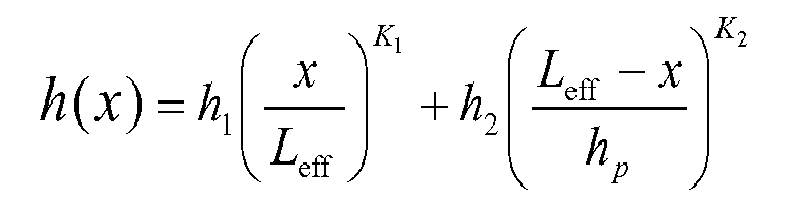
ist. x bezeichnet dabei den radialen Abstand zur Rollenmittelachse 23. h i ist dabei ein Startwert, der bevorzugt im Bereich von 0,015% bis 0,05% des Rollendurchmessers Dw liegt. h2 ist ein Zielwert, der bevorzugt im Bereich von 0,04% bis 0,25% des Rollendurchmessers DW liegt. Sowohl h1, als auch h2 sind in derFigur 2 lediglich exemplarisch dargestellt und liegen meist im Bereich einiger µm. K 1 ist eine Konstante, die bevorzugt im Bereich zwischen 10 und 50, besonders bevorzugt zwischen 20 und 50 liegt. K 2 ist eine Kostante, die bevorzugt im Bereich zwischen 10 und 50, besonders bevorzugt zwischen 10 und 30 liegt. Durch die entsprechend dem genannten Verlauf ausgebildete Krümmung des Abschnitts 27 ergibt sich eine besonders vorteilhafte Führung der Zylinderrollen 5 durch den Bord 13. Insbesondere werden durch die exakt definierte Berührung der Zylinderrolle 5 und des Bords 13 Kontaktspannungen minimiert und gleichzeitig der Berührpunkt radial soweit außen wie möglich gehalten. Kommt es zu einem Schränken (also einer Schrägstellung bezüglich einer senkrecht zur Laufbahn stehenden Achse) oder einem Kippen (also einer Schrägstellung bezüglich einer tangential zur Laufbahn verlaufenden Achse) der Rolle, so wandert der Berührpunkt zwischen der Zylinderrolle 5 und dem Bord 13 radial nach außen. Gleichzeitig zeichnet sich die Zylinderrolle 5 durch ein besonders geringes Reibmoment am Bord auf. - In
Figur 3 ist ausschnittsweise in schematischer Darstellung einer bekannten Zylinderrolle 101 dargestellt, die auf einer Laufbahn 103 des Innenrings 105 eines Zylinderrollenlagers abrollt. Die Zylinderrolle 101 weist radial außen liegend einen Bereich einer suboptimalen Kantenkürzung 121 auf. Entsprechend ist am Innenring 105 ein Einstich 107 vorgesehen. Zur Führung der Zylinderrolle 101 weist der Innenring 105 einen Bord 109 auf, an dem diese in einer Kontaktzone in einem Bereich 111 anliegt. Kommt es zu einem Schränken oder Kippen der Zylinderrolle 101, so wandert die Kontaktzone je nach Ausprägung nach außen zum Rand der Bords 109, so dass sie nunmehr im Bereich 111' liegt. - In der
Figur 4 ist in analoger Darstellung zurFigur 3 eine Ausführungsform der Erfindung dargestellt. Die Kantenkürzung 21 der Zylinderrolle 5 läuft im Bereich eines Einstichs 31 des Innenrings 3. Das Profil 27 wird am Bord 13 geführt. Bei geradem Lauf der Zylinderrolle 5 liegt diese in einer Kontaktzone im Bereich 33 am Bord an. Aufgrund der optimierten Ausführung des Abschnitts 27 wandert die Kontaktzone bei vergleichbaren Betriebsbedingungen des Zylinderrollenlagers jedoch nicht soweit nach außen wie bei bekannten Ausführungen (vgl.Figur 3 ). Bei Schränken oder Verkippen der Zylinderrolle 5 entsteht durch die Wechselwirkung des Abschnitts 27 mit dem Bord 13 ein Rückstellmoment auf die Zylinderrolle 5. Die Kontaktzone zum Bord 13 verändert daher ihre Lage nur vergleichweise gering und liegt in einem Bereich 35. Durch das verminderte Wandern der Kontaktzone beim Schränken oder Kippen wird das Reibmoment und die Ausfallwahrscheinlichkeit des Rolle-Bordkontakts minimiert und es lassen sich die erfindungsgemäßen Zylinderrollen 5 insbesondere in Wälzlagern mit geringer Bordhöhe einsetzen. - Selbst im Fall eines derart starken Schränken oder Kippens der Zylinderrolle 5, dass die Kontaktzone zum äußeren Rand des Bords 13 wandert, werden durch das Profil 27 Kantenspannungen zwischen der Zylinderrolle 5 und dem Bord 13 minimiert, so dass die Fressneigung der Zylinderrolle 5 am Bord 13 verringert wird. Die Zylinderrolle 5 wird durch das optimierte Profil 27 definiert am Bord 13 geführt. Dies resultiert auch in einem geringeren Reibmoment. Bei Borden geringer Höhe oder geringem Öffnungswinkel, die sich also parallel zur radialen Richtung erstrecken wird die Belastung der Zylinderrolle 5 minimiert.
- Zylinderrollen gemäß dem hier beschriebenen Ausführungsbeispiel lassen sich beispielsweise durch Hartdrehen oder elektrochemische Metallbearbeitung erzeugen. Dabei werden die Stirnseiten durch entsprechende Prozesse innerhalb enger Toleranzen gefertigt.
- In der
Figur 5 sind exemplarisch drei Verläufe für die Profile 27 gemäß der oben erläuterten Formel dargestellt. In horizontaler Richtung von links nach rechts erstreckt sich der Verlauf von x, während h(x) senkrecht dazu aufgetragen ist (vgl. auchFig. 2 ). Dabei sind zwei Einhüllende 201 und 205 gezeigt, die mit bevorzugten Extremwerten der Parameter h 1 und h 2, sowie K 1 und K 2 berechnet wurden. Für die Einhüllende 201 wurden die Parameter


gewählt. Für die Einhüllende 205 wurden die Parameter


gewählt. - Zwischen den Einhüllenden 201 und 205 ist eine weitere Kurve 203 gezeigt, die aus mittleren Werten der Parameter resultiert. Ausgehend vom linken Rand der
Figur 5 ist ausschnittsweise der mittlere Bereich ("Dimpel") der jeweiligen Zylinderrolle gezeigt, der im Wesentlichen waagerecht verläuft. Der Bereich geht dann in den in der gewählten Darstellung nach unten ausfallenden Bereich des optimierten Profils über, der wiederum weiter rechts ansteigt und in den hier nicht dargestellten Bereich der Kantenkürzung rw übergeht. Im Bereich des Profils läge die Zylinderrolle entsprechend am Bord des Rollenlagers an. - Alternativ lassen sich andere Ausführungsbeispiele der Erfindung ohne Vertiefung im mittleren Bereich beschreiben. Dies wäre im Vergleich zur
Figur 5 beispielsweise bei deutlich geringeren Werten von hp der Fall, so dass der Abschnitt gemäß der Kurve bereits im nahezu waagerechten Bereich endet und nicht zu einer Vertiefung abfällt. - Zusammenfassend lässt sich sagen, dass durch die erfindungsgemäßen Rollen mit definiertem Stirnseitenprofil die Kontaktzone bei normalen Betriebsbedingungen des Lagers in einem niedrigen Bereich des Bords gehalten wird und auch bei stärkerem Kippen oder Schränken ein Rückstellmoment ohne Auftreten von Kantenspannungen entsteht.
-
- 1
- Außenring
- 3
- Innenring
- 5
- Zylinderrollen
- 7
- Käfig
- 9
- Bord
- 11
- Bord
- 13
- Bord
- 21
- Kantenkürzung
- 23
- Rollenmittelachse
- 25
- Stirnseite
- 27
- gekrümmter Abschnitt
- 201, 205
- Einhüllende
- 203
- Kurve
Claims (10)
- Rolle für ein Rollenlager, wobei das Rollenlager wenigstens eine axiale Anlauffläche für die Rolle aufweist, wobei wenigstens ein sich in einem vorgebbaren Abstand von der Rollenmittenachse bis hin zu einem Kantenkürzungsbereich erstreckender Abschnitt einer Stirnseite der Rolle gemäß einer gekrümmten Kurve ausgebildet ist, die entsprechend dem Verlauf h verlaufend ausgebildet ist, wobei

ist und wobei x der Abstand von der Rollenmittenachse ist, wobei h1 und h2 jeweils kleiner als der Durchmesser Dw der Rolle sind, L eff der effektive Stirnseitenradius der Rolle, hp die Höhe des Abschnitts, sowie K1 und K2 Konstanten sind. - Rolle nach Anspruch 1, wobei

ist, wobei Dw der Rollendurchmesser und rw die Kantenkürzung ist. - Rolle nach Anspruch 1 oder 2, wobei h 1 im Bereich von 0,015% bis 0,05% des Rollendurchmessers Dw liegt.
- Rolle nach einem der Ansprüche 1 bis 3, wobei h2 im Bereich von 0,04% bis 0,25% des Rollendurchmessers Dw liegt.
- Rolle nach einem der Ansprüche 1 bis 4, wobei K1 und K 2 jeweils im Bereich von [10...50] liegen.
- Rolle nach einem der Ansprüche 1 bis 5, wobei K1 im Bereich von K 1 = [20...50] liegt.
- Rolle nach einem der Ansprüche 1 bis 6, wobei K 2 im Bereich von K 2 = [10...30] liegt.
- Rolle nach einem der Ansprüche 1 bis 7, wobei die Stirnseite einen bezüglich des Anlaufabschnitts radial innen liegenden Muldenabschnitt aufweist, der derart ausgebildet ist, dass sein axialer Abstand zur axialen Anlauffläche grö-βer ist als der axiale Abstand des Anlaufabschnitts zur axialen Anlauffläche.
- Rolle nach einem der Ansprüche 1 bis 8, wobei die Rolle als eine Zylinderrolle eines Zylinderrollenlagers ausgebildet ist.
- Rollenlager mit Rollen nach einem der Ansprüche 1 bis 9.
Applications Claiming Priority (1)
| Application Number | Priority Date | Filing Date | Title |
|---|---|---|---|
| DE201010018553 DE102010018553A1 (de) | 2010-04-28 | 2010-04-28 | Rolle und Rollenlager |
Publications (2)
| Publication Number | Publication Date |
|---|---|
| EP2383478A1 true EP2383478A1 (de) | 2011-11-02 |
| EP2383478B1 EP2383478B1 (de) | 2013-07-24 |
Family
ID=44242494
Family Applications (1)
| Application Number | Title | Priority Date | Filing Date |
|---|---|---|---|
| EP20110163621 Active EP2383478B1 (de) | 2010-04-28 | 2011-04-26 | Rolle und Rollenlager |
Country Status (3)
| Country | Link |
|---|---|
| EP (1) | EP2383478B1 (de) |
| CN (1) | CN102252025B (de) |
| DE (1) | DE102010018553A1 (de) |
Cited By (3)
| Publication number | Priority date | Publication date | Assignee | Title |
|---|---|---|---|---|
| EP2787225A4 (de) * | 2011-12-02 | 2015-06-03 | Ntn Toyo Bearing Co Ltd | Rollenlager |
| EP2884126A1 (de) * | 2013-12-13 | 2015-06-17 | Aktiebolaget SKF | Laufbahnelement und Rollenlager mit dem Laufbahnelement |
| CN118361465A (zh) * | 2024-04-10 | 2024-07-19 | 瓦房店轴承集团国家轴承工程技术研究中心有限公司 | 圆柱滚子轴承内圈挡边球基面设计方法 |
Families Citing this family (2)
| Publication number | Priority date | Publication date | Assignee | Title |
|---|---|---|---|---|
| CN105090236B (zh) * | 2014-04-15 | 2019-07-12 | 舍弗勒技术股份两合公司 | 圆柱滚子轴承 |
| DE102014210688A1 (de) | 2014-06-05 | 2015-12-17 | Zf Friedrichshafen Ag | Rollenlager, insbesondere Zylinderrollenlager |
Citations (5)
| Publication number | Priority date | Publication date | Assignee | Title |
|---|---|---|---|---|
| US3713712A (en) * | 1971-03-29 | 1973-01-30 | Rollway Bearing Co Inc | Hollow ended bearing roller |
| JPH04331813A (ja) * | 1991-04-30 | 1992-11-19 | Ntn Corp | 円すいころ軸受 |
| DE10230357B4 (de) | 2001-07-05 | 2006-10-05 | Nsk Ltd. | Wälzlager |
| US20090003747A1 (en) * | 2005-12-21 | 2009-01-01 | Schaeffler Kg | Rolling Bearing |
| DE102008028164A1 (de) * | 2008-06-12 | 2010-01-07 | Ab Skf | Rolle und Rollenlager mit der Rolle |
Family Cites Families (7)
| Publication number | Priority date | Publication date | Assignee | Title |
|---|---|---|---|---|
| EP0631061A1 (de) * | 1993-06-23 | 1994-12-28 | Felix Sanchez Sanchez | Minimal-Reibungszylinder und/oder -Kegelrollenlager |
| JP2002089548A (ja) * | 2000-09-18 | 2002-03-27 | Nsk Ltd | 鍔付円筒ころ軸受 |
| JP2002310160A (ja) * | 2001-04-10 | 2002-10-23 | Ntn Corp | 円筒ころ軸受 |
| JP2004353744A (ja) * | 2003-05-28 | 2004-12-16 | Nsk Ltd | ころ軸受 |
| EP1632685B1 (de) * | 2003-06-12 | 2013-07-10 | NSK Ltd. | Zylindrisches rollenlager |
| JP2006090516A (ja) * | 2004-09-27 | 2006-04-06 | Ntn Corp | 円筒ころ軸受 |
| DE102005061179A1 (de) * | 2005-12-21 | 2007-06-28 | Schaeffler Kg | Wälzlager und Verfahren zu dessen Herstellung |
-
2010
- 2010-04-28 DE DE201010018553 patent/DE102010018553A1/de not_active Ceased
-
2011
- 2011-04-26 EP EP20110163621 patent/EP2383478B1/de active Active
- 2011-04-28 CN CN201110195163.6A patent/CN102252025B/zh active Active
Patent Citations (5)
| Publication number | Priority date | Publication date | Assignee | Title |
|---|---|---|---|---|
| US3713712A (en) * | 1971-03-29 | 1973-01-30 | Rollway Bearing Co Inc | Hollow ended bearing roller |
| JPH04331813A (ja) * | 1991-04-30 | 1992-11-19 | Ntn Corp | 円すいころ軸受 |
| DE10230357B4 (de) | 2001-07-05 | 2006-10-05 | Nsk Ltd. | Wälzlager |
| US20090003747A1 (en) * | 2005-12-21 | 2009-01-01 | Schaeffler Kg | Rolling Bearing |
| DE102008028164A1 (de) * | 2008-06-12 | 2010-01-07 | Ab Skf | Rolle und Rollenlager mit der Rolle |
Cited By (3)
| Publication number | Priority date | Publication date | Assignee | Title |
|---|---|---|---|---|
| EP2787225A4 (de) * | 2011-12-02 | 2015-06-03 | Ntn Toyo Bearing Co Ltd | Rollenlager |
| EP2884126A1 (de) * | 2013-12-13 | 2015-06-17 | Aktiebolaget SKF | Laufbahnelement und Rollenlager mit dem Laufbahnelement |
| CN118361465A (zh) * | 2024-04-10 | 2024-07-19 | 瓦房店轴承集团国家轴承工程技术研究中心有限公司 | 圆柱滚子轴承内圈挡边球基面设计方法 |
Also Published As
| Publication number | Publication date |
|---|---|
| CN102252025A (zh) | 2011-11-23 |
| CN102252025B (zh) | 2016-01-20 |
| DE102010018553A1 (de) | 2012-01-19 |
| EP2383478B1 (de) | 2013-07-24 |
Similar Documents
| Publication | Publication Date | Title |
|---|---|---|
| EP2715169B1 (de) | Geometriekonzept für eine rolle eines kegelrollenlagers | |
| DE102010034254B4 (de) | Käfig für ein Rollenlager | |
| EP2383478B1 (de) | Rolle und Rollenlager | |
| DE102010062481B3 (de) | Geometriekonzept für einen Rolle-Bord-Kontakt bei Rollenlagern | |
| DE112011101552B4 (de) | Axialkäfig für zylindrische Wälzkörper | |
| DE102011076328B4 (de) | Geometriekonzept für einen Bord eines Rollenlagers | |
| DE102013016949A1 (de) | Rollenlager für mindestens zwei Reihen von Rollelementen, insbesondere für den Tunnelbau | |
| EP2893207B1 (de) | Axialkäfig für zylindrische wälzkörper | |
| EP1963695A1 (de) | Wälzlager | |
| WO2007071229A1 (de) | Wälzlager mit verbesserter bordgeometrie | |
| EP2884126B1 (de) | Laufbahnelement und Rollenlager mit dem Laufbahnelement | |
| WO2011113647A2 (de) | Kegelrollenlager mit profilierter laufbahn | |
| DE102014219702A1 (de) | Laufbahnstruktur für ein Wälzlager und Verfahren | |
| EP3810944B1 (de) | Axialwälzlager | |
| DE10004584C1 (de) | Zylinderrollenlager | |
| DE102014219705A1 (de) | Lagerring | |
| DE102008049976A1 (de) | Federbeinlager sowie Federbein | |
| DE102019115309A1 (de) | Lagerscheibe für ein Axialrollenlager | |
| DE102016208829A1 (de) | Käfigsegment eines Wälzlagers | |
| DE102016202935A1 (de) | Reibungsarmes Kegelrollenlager | |
| DE102005058149A1 (de) | Schrägrollenlager mit gekrümmten Laufbahnen | |
| EP2452091B1 (de) | Kugelgelenk | |
| WO2007028469A1 (de) | Schrägscheiben-schwenklager | |
| DE102013221470A1 (de) | Rollenhülse | |
| DE102014204858A1 (de) | Wälzlager mit axial benachbarten Walzen |
Legal Events
| Date | Code | Title | Description |
|---|---|---|---|
| AK | Designated contracting states |
Kind code of ref document: A1 Designated state(s): AL AT BE BG CH CY CZ DE DK EE ES FI FR GB GR HR HU IE IS IT LI LT LU LV MC MK MT NL NO PL PT RO RS SE SI SK SM TR |
|
| AX | Request for extension of the european patent |
Extension state: BA ME |
|
| PUAI | Public reference made under article 153(3) epc to a published international application that has entered the european phase |
Free format text: ORIGINAL CODE: 0009012 |
|
| 17P | Request for examination filed |
Effective date: 20120502 |
|
| GRAP | Despatch of communication of intention to grant a patent |
Free format text: ORIGINAL CODE: EPIDOSNIGR1 |
|
| GRAS | Grant fee paid |
Free format text: ORIGINAL CODE: EPIDOSNIGR3 |
|
| GRAA | (expected) grant |
Free format text: ORIGINAL CODE: 0009210 |
|
| AK | Designated contracting states |
Kind code of ref document: B1 Designated state(s): AL AT BE BG CH CY CZ DE DK EE ES FI FR GB GR HR HU IE IS IT LI LT LU LV MC MK MT NL NO PL PT RO RS SE SI SK SM TR |
|
| REG | Reference to a national code |
Ref country code: GB Ref legal event code: FG4D Free format text: NOT ENGLISH |
|
| REG | Reference to a national code |
Ref country code: CH Ref legal event code: EP |
|
| REG | Reference to a national code |
Ref country code: AT Ref legal event code: REF Ref document number: 623639 Country of ref document: AT Kind code of ref document: T Effective date: 20130815 |
|
| REG | Reference to a national code |
Ref country code: IE Ref legal event code: FG4D Free format text: LANGUAGE OF EP DOCUMENT: GERMAN |
|
| REG | Reference to a national code |
Ref country code: DE Ref legal event code: R096 Ref document number: 502011001075 Country of ref document: DE Effective date: 20130919 |
|
| REG | Reference to a national code |
Ref country code: NL Ref legal event code: VDEP Effective date: 20130724 |
|
| REG | Reference to a national code |
Ref country code: LT Ref legal event code: MG4D |
|
| PG25 | Lapsed in a contracting state [announced via postgrant information from national office to epo] |
Ref country code: HR Free format text: LAPSE BECAUSE OF FAILURE TO SUBMIT A TRANSLATION OF THE DESCRIPTION OR TO PAY THE FEE WITHIN THE PRESCRIBED TIME-LIMIT Effective date: 20130724 Ref country code: PT Free format text: LAPSE BECAUSE OF FAILURE TO SUBMIT A TRANSLATION OF THE DESCRIPTION OR TO PAY THE FEE WITHIN THE PRESCRIBED TIME-LIMIT Effective date: 20131125 Ref country code: CY Free format text: LAPSE BECAUSE OF FAILURE TO SUBMIT A TRANSLATION OF THE DESCRIPTION OR TO PAY THE FEE WITHIN THE PRESCRIBED TIME-LIMIT Effective date: 20130724 Ref country code: NO Free format text: LAPSE BECAUSE OF FAILURE TO SUBMIT A TRANSLATION OF THE DESCRIPTION OR TO PAY THE FEE WITHIN THE PRESCRIBED TIME-LIMIT Effective date: 20131024 Ref country code: IS Free format text: LAPSE BECAUSE OF FAILURE TO SUBMIT A TRANSLATION OF THE DESCRIPTION OR TO PAY THE FEE WITHIN THE PRESCRIBED TIME-LIMIT Effective date: 20131124 Ref country code: LT Free format text: LAPSE BECAUSE OF FAILURE TO SUBMIT A TRANSLATION OF THE DESCRIPTION OR TO PAY THE FEE WITHIN THE PRESCRIBED TIME-LIMIT Effective date: 20130724 Ref country code: SE Free format text: LAPSE BECAUSE OF FAILURE TO SUBMIT A TRANSLATION OF THE DESCRIPTION OR TO PAY THE FEE WITHIN THE PRESCRIBED TIME-LIMIT Effective date: 20130724 |
|
| PG25 | Lapsed in a contracting state [announced via postgrant information from national office to epo] |
Ref country code: FI Free format text: LAPSE BECAUSE OF FAILURE TO SUBMIT A TRANSLATION OF THE DESCRIPTION OR TO PAY THE FEE WITHIN THE PRESCRIBED TIME-LIMIT Effective date: 20130724 Ref country code: PL Free format text: LAPSE BECAUSE OF FAILURE TO SUBMIT A TRANSLATION OF THE DESCRIPTION OR TO PAY THE FEE WITHIN THE PRESCRIBED TIME-LIMIT Effective date: 20130724 Ref country code: NL Free format text: LAPSE BECAUSE OF FAILURE TO SUBMIT A TRANSLATION OF THE DESCRIPTION OR TO PAY THE FEE WITHIN THE PRESCRIBED TIME-LIMIT Effective date: 20130724 Ref country code: LV Free format text: LAPSE BECAUSE OF FAILURE TO SUBMIT A TRANSLATION OF THE DESCRIPTION OR TO PAY THE FEE WITHIN THE PRESCRIBED TIME-LIMIT Effective date: 20130724 Ref country code: GR Free format text: LAPSE BECAUSE OF FAILURE TO SUBMIT A TRANSLATION OF THE DESCRIPTION OR TO PAY THE FEE WITHIN THE PRESCRIBED TIME-LIMIT Effective date: 20131025 Ref country code: SI Free format text: LAPSE BECAUSE OF FAILURE TO SUBMIT A TRANSLATION OF THE DESCRIPTION OR TO PAY THE FEE WITHIN THE PRESCRIBED TIME-LIMIT Effective date: 20130724 |
|
| PG25 | Lapsed in a contracting state [announced via postgrant information from national office to epo] |
Ref country code: RO Free format text: LAPSE BECAUSE OF FAILURE TO SUBMIT A TRANSLATION OF THE DESCRIPTION OR TO PAY THE FEE WITHIN THE PRESCRIBED TIME-LIMIT Effective date: 20130724 Ref country code: DK Free format text: LAPSE BECAUSE OF FAILURE TO SUBMIT A TRANSLATION OF THE DESCRIPTION OR TO PAY THE FEE WITHIN THE PRESCRIBED TIME-LIMIT Effective date: 20130724 Ref country code: SK Free format text: LAPSE BECAUSE OF FAILURE TO SUBMIT A TRANSLATION OF THE DESCRIPTION OR TO PAY THE FEE WITHIN THE PRESCRIBED TIME-LIMIT Effective date: 20130724 Ref country code: CZ Free format text: LAPSE BECAUSE OF FAILURE TO SUBMIT A TRANSLATION OF THE DESCRIPTION OR TO PAY THE FEE WITHIN THE PRESCRIBED TIME-LIMIT Effective date: 20130724 Ref country code: EE Free format text: LAPSE BECAUSE OF FAILURE TO SUBMIT A TRANSLATION OF THE DESCRIPTION OR TO PAY THE FEE WITHIN THE PRESCRIBED TIME-LIMIT Effective date: 20130724 |
|
| PG25 | Lapsed in a contracting state [announced via postgrant information from national office to epo] |
Ref country code: ES Free format text: LAPSE BECAUSE OF FAILURE TO SUBMIT A TRANSLATION OF THE DESCRIPTION OR TO PAY THE FEE WITHIN THE PRESCRIBED TIME-LIMIT Effective date: 20130724 Ref country code: IT Free format text: LAPSE BECAUSE OF FAILURE TO SUBMIT A TRANSLATION OF THE DESCRIPTION OR TO PAY THE FEE WITHIN THE PRESCRIBED TIME-LIMIT Effective date: 20130724 |
|
| PLBE | No opposition filed within time limit |
Free format text: ORIGINAL CODE: 0009261 |
|
| STAA | Information on the status of an ep patent application or granted ep patent |
Free format text: STATUS: NO OPPOSITION FILED WITHIN TIME LIMIT |
|
| 26N | No opposition filed |
Effective date: 20140425 |
|
| REG | Reference to a national code |
Ref country code: DE Ref legal event code: R097 Ref document number: 502011001075 Country of ref document: DE Effective date: 20140425 |
|
| PG25 | Lapsed in a contracting state [announced via postgrant information from national office to epo] |
Ref country code: MC Free format text: LAPSE BECAUSE OF FAILURE TO SUBMIT A TRANSLATION OF THE DESCRIPTION OR TO PAY THE FEE WITHIN THE PRESCRIBED TIME-LIMIT Effective date: 20130724 Ref country code: LU Free format text: LAPSE BECAUSE OF FAILURE TO SUBMIT A TRANSLATION OF THE DESCRIPTION OR TO PAY THE FEE WITHIN THE PRESCRIBED TIME-LIMIT Effective date: 20140426 |
|
| REG | Reference to a national code |
Ref country code: CH Ref legal event code: PL |
|
| REG | Reference to a national code |
Ref country code: IE Ref legal event code: MM4A |
|
| PG25 | Lapsed in a contracting state [announced via postgrant information from national office to epo] |
Ref country code: LI Free format text: LAPSE BECAUSE OF NON-PAYMENT OF DUE FEES Effective date: 20140430 Ref country code: CH Free format text: LAPSE BECAUSE OF NON-PAYMENT OF DUE FEES Effective date: 20140430 |
|
| PG25 | Lapsed in a contracting state [announced via postgrant information from national office to epo] |
Ref country code: IE Free format text: LAPSE BECAUSE OF NON-PAYMENT OF DUE FEES Effective date: 20140426 |
|
| PG25 | Lapsed in a contracting state [announced via postgrant information from national office to epo] |
Ref country code: MT Free format text: LAPSE BECAUSE OF FAILURE TO SUBMIT A TRANSLATION OF THE DESCRIPTION OR TO PAY THE FEE WITHIN THE PRESCRIBED TIME-LIMIT Effective date: 20130724 |
|
| REG | Reference to a national code |
Ref country code: FR Ref legal event code: PLFP Year of fee payment: 6 |
|
| PG25 | Lapsed in a contracting state [announced via postgrant information from national office to epo] |
Ref country code: SM Free format text: LAPSE BECAUSE OF FAILURE TO SUBMIT A TRANSLATION OF THE DESCRIPTION OR TO PAY THE FEE WITHIN THE PRESCRIBED TIME-LIMIT Effective date: 20130724 |
|
| PG25 | Lapsed in a contracting state [announced via postgrant information from national office to epo] |
Ref country code: BG Free format text: LAPSE BECAUSE OF FAILURE TO SUBMIT A TRANSLATION OF THE DESCRIPTION OR TO PAY THE FEE WITHIN THE PRESCRIBED TIME-LIMIT Effective date: 20130724 Ref country code: RS Free format text: LAPSE BECAUSE OF FAILURE TO SUBMIT A TRANSLATION OF THE DESCRIPTION OR TO PAY THE FEE WITHIN THE PRESCRIBED TIME-LIMIT Effective date: 20130724 |
|
| PG25 | Lapsed in a contracting state [announced via postgrant information from national office to epo] |
Ref country code: TR Free format text: LAPSE BECAUSE OF FAILURE TO SUBMIT A TRANSLATION OF THE DESCRIPTION OR TO PAY THE FEE WITHIN THE PRESCRIBED TIME-LIMIT Effective date: 20130724 Ref country code: BE Free format text: LAPSE BECAUSE OF FAILURE TO SUBMIT A TRANSLATION OF THE DESCRIPTION OR TO PAY THE FEE WITHIN THE PRESCRIBED TIME-LIMIT Effective date: 20140430 Ref country code: HU Free format text: LAPSE BECAUSE OF FAILURE TO SUBMIT A TRANSLATION OF THE DESCRIPTION OR TO PAY THE FEE WITHIN THE PRESCRIBED TIME-LIMIT; INVALID AB INITIO Effective date: 20110426 |
|
| PGFP | Annual fee paid to national office [announced via postgrant information from national office to epo] |
Ref country code: GB Payment date: 20160502 Year of fee payment: 6 |
|
| PGFP | Annual fee paid to national office [announced via postgrant information from national office to epo] |
Ref country code: FR Payment date: 20160427 Year of fee payment: 6 |
|
| REG | Reference to a national code |
Ref country code: AT Ref legal event code: MM01 Ref document number: 623639 Country of ref document: AT Kind code of ref document: T Effective date: 20160426 |
|
| PG25 | Lapsed in a contracting state [announced via postgrant information from national office to epo] |
Ref country code: AT Free format text: LAPSE BECAUSE OF NON-PAYMENT OF DUE FEES Effective date: 20160426 |
|
| GBPC | Gb: european patent ceased through non-payment of renewal fee |
Effective date: 20170426 |
|
| REG | Reference to a national code |
Ref country code: FR Ref legal event code: ST Effective date: 20171229 |
|
| PG25 | Lapsed in a contracting state [announced via postgrant information from national office to epo] |
Ref country code: FR Free format text: LAPSE BECAUSE OF NON-PAYMENT OF DUE FEES Effective date: 20170502 |
|
| PG25 | Lapsed in a contracting state [announced via postgrant information from national office to epo] |
Ref country code: GB Free format text: LAPSE BECAUSE OF NON-PAYMENT OF DUE FEES Effective date: 20170426 |
|
| PG25 | Lapsed in a contracting state [announced via postgrant information from national office to epo] |
Ref country code: MK Free format text: LAPSE BECAUSE OF FAILURE TO SUBMIT A TRANSLATION OF THE DESCRIPTION OR TO PAY THE FEE WITHIN THE PRESCRIBED TIME-LIMIT Effective date: 20130724 |
|
| PG25 | Lapsed in a contracting state [announced via postgrant information from national office to epo] |
Ref country code: AL Free format text: LAPSE BECAUSE OF FAILURE TO SUBMIT A TRANSLATION OF THE DESCRIPTION OR TO PAY THE FEE WITHIN THE PRESCRIBED TIME-LIMIT Effective date: 20130724 |
|
| P01 | Opt-out of the competence of the unified patent court (upc) registered |
Effective date: 20230513 |
|
| PGFP | Annual fee paid to national office [announced via postgrant information from national office to epo] |
Ref country code: DE Payment date: 20260421 Year of fee payment: 16 |