EP2383065A2 - Dual seam electric resistance welded tubes - Google Patents
Dual seam electric resistance welded tubes Download PDFInfo
- Publication number
- EP2383065A2 EP2383065A2 EP11275070A EP11275070A EP2383065A2 EP 2383065 A2 EP2383065 A2 EP 2383065A2 EP 11275070 A EP11275070 A EP 11275070A EP 11275070 A EP11275070 A EP 11275070A EP 2383065 A2 EP2383065 A2 EP 2383065A2
- Authority
- EP
- European Patent Office
- Prior art keywords
- forming
- roller
- tubular product
- convergence angle
- coils
- Prior art date
- Legal status (The legal status is an assumption and is not a legal conclusion. Google has not performed a legal analysis and makes no representation as to the accuracy of the status listed.)
- Granted
Links
- 230000009977 dual effect Effects 0.000 title claims abstract description 17
- 238000003466 welding Methods 0.000 claims abstract description 27
- 238000000034 method Methods 0.000 claims abstract description 22
- 239000000463 material Substances 0.000 claims abstract description 14
- 239000007769 metal material Substances 0.000 claims abstract description 5
- 239000000047 product Substances 0.000 description 13
- 239000002184 metal Substances 0.000 description 5
- 238000012986 modification Methods 0.000 description 2
- 230000004048 modification Effects 0.000 description 2
- 230000006978 adaptation Effects 0.000 description 1
- 230000002411 adverse Effects 0.000 description 1
- 238000005452 bending Methods 0.000 description 1
- 239000007795 chemical reaction product Substances 0.000 description 1
- 238000004581 coalescence Methods 0.000 description 1
- 230000000694 effects Effects 0.000 description 1
- 239000007772 electrode material Substances 0.000 description 1
- 239000012467 final product Substances 0.000 description 1
- 230000006698 induction Effects 0.000 description 1
- 238000005304 joining Methods 0.000 description 1
- 238000003825 pressing Methods 0.000 description 1
- 238000009751 slip forming Methods 0.000 description 1
Images

Classifications
-
- B—PERFORMING OPERATIONS; TRANSPORTING
- B21—MECHANICAL METAL-WORKING WITHOUT ESSENTIALLY REMOVING MATERIAL; PUNCHING METAL
- B21C—MANUFACTURE OF METAL SHEETS, WIRE, RODS, TUBES OR PROFILES, OTHERWISE THAN BY ROLLING; AUXILIARY OPERATIONS USED IN CONNECTION WITH METAL-WORKING WITHOUT ESSENTIALLY REMOVING MATERIAL
- B21C37/00—Manufacture of metal sheets, bars, wire, tubes or like semi-manufactured products, not otherwise provided for; Manufacture of tubes of special shape
- B21C37/06—Manufacture of metal sheets, bars, wire, tubes or like semi-manufactured products, not otherwise provided for; Manufacture of tubes of special shape of tubes or metal hoses; Combined procedures for making tubes, e.g. for making multi-wall tubes
- B21C37/08—Making tubes with welded or soldered seams
- B21C37/083—Supply, or operations combined with supply, of strip material
-
- B—PERFORMING OPERATIONS; TRANSPORTING
- B21—MECHANICAL METAL-WORKING WITHOUT ESSENTIALLY REMOVING MATERIAL; PUNCHING METAL
- B21B—ROLLING OF METAL
- B21B1/00—Metal-rolling methods or mills for making semi-finished products of solid or profiled cross-section; Sequence of operations in milling trains; Layout of rolling-mill plant, e.g. grouping of stands; Succession of passes or of sectional pass alternations
- B21B1/38—Metal-rolling methods or mills for making semi-finished products of solid or profiled cross-section; Sequence of operations in milling trains; Layout of rolling-mill plant, e.g. grouping of stands; Succession of passes or of sectional pass alternations for rolling sheets of limited length, e.g. folded sheets, superimposed sheets, pack rolling
-
- B—PERFORMING OPERATIONS; TRANSPORTING
- B21—MECHANICAL METAL-WORKING WITHOUT ESSENTIALLY REMOVING MATERIAL; PUNCHING METAL
- B21C—MANUFACTURE OF METAL SHEETS, WIRE, RODS, TUBES OR PROFILES, OTHERWISE THAN BY ROLLING; AUXILIARY OPERATIONS USED IN CONNECTION WITH METAL-WORKING WITHOUT ESSENTIALLY REMOVING MATERIAL
- B21C37/00—Manufacture of metal sheets, bars, wire, tubes or like semi-manufactured products, not otherwise provided for; Manufacture of tubes of special shape
- B21C37/06—Manufacture of metal sheets, bars, wire, tubes or like semi-manufactured products, not otherwise provided for; Manufacture of tubes of special shape of tubes or metal hoses; Combined procedures for making tubes, e.g. for making multi-wall tubes
- B21C37/08—Making tubes with welded or soldered seams
- B21C37/0803—Making tubes with welded or soldered seams the tubes having a special shape, e.g. polygonal tubes
-
- B—PERFORMING OPERATIONS; TRANSPORTING
- B23—MACHINE TOOLS; METAL-WORKING NOT OTHERWISE PROVIDED FOR
- B23K—SOLDERING OR UNSOLDERING; WELDING; CLADDING OR PLATING BY SOLDERING OR WELDING; CUTTING BY APPLYING HEAT LOCALLY, e.g. FLAME CUTTING; WORKING BY LASER BEAM
- B23K11/00—Resistance welding; Severing by resistance heating
- B23K11/06—Resistance welding; Severing by resistance heating using roller electrodes
- B23K11/061—Resistance welding; Severing by resistance heating using roller electrodes for welding rectilinear seams
- B23K11/062—Resistance welding; Severing by resistance heating using roller electrodes for welding rectilinear seams for welding longitudinal seams of tubes
-
- B—PERFORMING OPERATIONS; TRANSPORTING
- B23—MACHINE TOOLS; METAL-WORKING NOT OTHERWISE PROVIDED FOR
- B23K—SOLDERING OR UNSOLDERING; WELDING; CLADDING OR PLATING BY SOLDERING OR WELDING; CUTTING BY APPLYING HEAT LOCALLY, e.g. FLAME CUTTING; WORKING BY LASER BEAM
- B23K11/00—Resistance welding; Severing by resistance heating
- B23K11/08—Seam welding not restricted to one of the preceding subgroups
- B23K11/087—Seam welding not restricted to one of the preceding subgroups for rectilinear seams
- B23K11/0873—Seam welding not restricted to one of the preceding subgroups for rectilinear seams of the longitudinal seam of tubes
Definitions
- the present invention is directed to methods and apparatuses for forming dual seam welded tubes.
- Electric resistance welding refers to a group of welding processes such as spot and upset welding that produce coalescence of faying surfaces where heat to form the weld is generated by the resistance of the welding current through the workpieces. Some factors influencing heat or welding temperatures are the proportions of the workpieces, the electrode materials, electrode geometry, electrode pressing force, weld current and weld time. Small pools of molten metal are formed at the point of greatest electrical resistance (the connecting surfaces) as a high current (100-100,000 A) is passed through the metal. In general, resistance welding methods are efficient and cause little pollution, but their applications are limited to relatively thin materials and the equipment cost can be high.
- Upset welding relies on two electrodes to apply current to join metal sheets. However, instead of pointed electrodes, contacts or induction coils are used to induce current, making it possible to make long continuous welds.
- Upset welding is mainly used on the seams of tubes and pipes for its ease and accuracy.
- the resulting weld is extremely durable due to the length of the contact area.
- a coil of metal sheet is uncoiled to flat, and formed continuously into a tube using forming rolls.
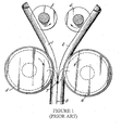
- Tubes formed from metal sheet may be formed with a single seam or with dual seams. Dual seam mills are known where two semi-circular sections are formed separately and then brought together for welding. This process requires some twisting or deformation of the semi-circular sections prior to joining. As shown in prior art Figure 1 , welding pressure at the welding point (7) between the two semi-tubes (1, 2) is produced by deflection between the spreaders (3, 4) and the electrode rollers (5, 6). However, excessive bending or twisting will result in an inferior product, particularly as the diameter of tube becomes larger.
- the present invention comprises improved methods and apparatuses for forming a dual seam welded tubular product.
- the invention comprises a method which forms two half-tubes and welds them together with a low convergence angle, which may be less than about 4°.
- the invention may comprise an apparatus which has at least one upper forming roller pair, and at least one lower forming roller pair, where the upper and lower roller pairs are interleaved in order to reduce the convergence angle at the welding point.
- Figure 1 is a schematic depiction of a prior art dual seam forming process.
- Figure 2 is a cross-sectional view of the "forming flower" produced by one embodiment of the present invention.
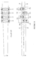
- Figures 3A (top plan) and 3B (side view) are a schematic depiction of the forming rollers of one embodiment.
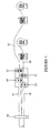
- Figure 4 is a schematic depiction of one embodiment of a dual seam forming apparatus of the present invention.
- the invention relates to a method and apparatus of forming a dual seam welded tubular product.
- all terms not defined herein have their common art-recognized meanings.
- the following description is of a specific embodiment or a particular use of the invention, it is intended to be illustrative only, and not limiting of the claimed invention.
- the following description is intended to cover all alternatives, modifications and equivalents that are included in the spirit and scope of the invention, as defined in the appended claims.
- one aspect of the invention comprises amethod of continuously forming a dual seam welded tubular product, comprising the steps of:
- the invention comprises an apparatus for continuously forming a dual seam welded tubular product from two coils of sheet metal material, comprising:
- the tubular products produced by methods and apparatuses of the present invention are continuously formed from two substantially similar, opposed semi-circular half-tubes.
- Each half-tube is formed from a length of flat sheet material, typically stored as a coil, which is passed through at least one pair, and preferably multiple pairs of forming rollers.
- Each pair of forming rollers brings the initially flat material closer to its final semi-circular shape.
- the changing shape of material is termed a "forming flower", as shown in Figure 2 .
- the upper coil of sheet material (10) is fed into a first upper forming roller pair (12), consisting of an upper concave roller (12A), and a lower convex roller (12B).
- the first forming roller pair produces an intermediate shape.
- the material then passes through one or more additional forming roller pairs (14A, 14B) to create the final semi-circular shape of the upper half-tube (16).
- the lower coil of sheet material is fed through a first lower forming roller pair (22), consisting of a lower concave roller (22A) and an upper convex roller (22B).
- a first lower forming roller pair consisting of a lower concave roller (22A) and an upper convex roller (22B).
- additional forming roller pairs 24A, 24B) create the final shape of the lower half-tube (26).
- the convergence angle is the angle at which the lower half-tube and the upper half-tube meet at during the forming and welding process.
- that convergence angle is large, which reduces the quality of the welded seams.
- the range of the convergence angle is below about 4°, preferably between about 2° to about 4°. Keeping the convergence angle within this range enables the proximity effect to increase the efficiency substantially.
- the heat affected zone is minimized as only the faying edges are heated.
- Another benefit to keeping the convergence angle small is a homogenous strain profile around the circumference of the tube. With higher angles, such as those above 4°, the edges being welded are strained excessively as their direction changes abruptly at the welding point (30), causing irregularities in the finished product.
- the apparatus is arranged to minimize the convergence angle. This is accomplished by overlapping or interleaving the upper and lower forming rollers, such that the two half-tubes are formed closer together.
- the lower roller (12B, 14B) of the upper roller pair is substantially horizontally planar with the upper roller (22B, 24B) of the lower roller pair.
- the convergence angle is less than about 4°, and is preferably about 3°.
- the term "about” denotes a possible variance of 10% above or below the stated value and may also reflect imprecision of the available methods of measuring the stated value.
- Welding occurs at the welding point (30) using an electric resistance welding device (40), which are well known in the art, and further description thereof is unnecessary.
- the specific nature of the welding method is not an essential element of the present invention.
- the tubular product will have a circumference equal to approximately twice the width of the coiled material.
- the low convergence angle permitted by implementing the present invention allows large diameter product to be produced by the dual seam welding process.
- tubular products having diameters in excess of about 26" may easily be produced.
- Single seam products have not exceeded 26" in diameter because of limitations of the width of the coiled sheet material. Larger diameter dual seam products have not been made due to the stresses and inconsistencies produced during the forming process in the prior art.
Abstract
Description
- The present invention is directed to methods and apparatuses for forming dual seam welded tubes.
- Electric resistance welding (ERW) refers to a group of welding processes such as spot and upset welding that produce coalescence of faying surfaces where heat to form the weld is generated by the resistance of the welding current through the workpieces. Some factors influencing heat or welding temperatures are the proportions of the workpieces, the electrode materials, electrode geometry, electrode pressing force, weld current and weld time. Small pools of molten metal are formed at the point of greatest electrical resistance (the connecting surfaces) as a high current (100-100,000 A) is passed through the metal. In general, resistance welding methods are efficient and cause little pollution, but their applications are limited to relatively thin materials and the equipment cost can be high.
- Upset welding relies on two electrodes to apply current to join metal sheets. However, instead of pointed electrodes, contacts or induction coils are used to induce current, making it possible to make long continuous welds.
- Upset welding is mainly used on the seams of tubes and pipes for its ease and accuracy. The resulting weld is extremely durable due to the length of the contact area. A coil of metal sheet is uncoiled to flat, and formed continuously into a tube using forming rolls.
- Tubes formed from metal sheet may be formed with a single seam or with dual seams. Dual seam mills are known where two semi-circular sections are formed separately and then brought together for welding. This process requires some twisting or deformation of the semi-circular sections prior to joining. As shown in prior art
Figure 1 , welding pressure at the welding point (7) between the two semi-tubes (1, 2) is produced by deflection between the spreaders (3, 4) and the electrode rollers (5, 6). However, excessive bending or twisting will result in an inferior product, particularly as the diameter of tube becomes larger. - There is a need in the art for an improved dual seam welding process, particularly for tubular products of a larger diameter.
- The present invention comprises improved methods and apparatuses for forming a dual seam welded tubular product. In one aspect, the invention comprises a method which forms two half-tubes and welds them together with a low convergence angle, which may be less than about 4°. In another aspect, the invention may comprise an apparatus which has at least one upper forming roller pair, and at least one lower forming roller pair, where the upper and lower roller pairs are interleaved in order to reduce the convergence angle at the welding point.
- In the drawings, like elements are assigned like reference numerals. The drawings are not necessarily to scale, with the emphasis instead placed upon the principles of the present invention. Additionally, each of the embodiments depicted are but one of a number of possible arrangements utilizing the fundamental concepts of the present invention. The drawings are briefly described as follows:
-
Figure 1 is a schematic depiction of a prior art dual seam forming process. -
Figure 2 is a cross-sectional view of the "forming flower" produced by one embodiment of the present invention. -
Figures 3A (top plan) and 3B (side view) are a schematic depiction of the forming rollers of one embodiment. -
Figure 4 is a schematic depiction of one embodiment of a dual seam forming apparatus of the present invention. - The invention relates to a method and apparatus of forming a dual seam welded tubular product. When describing the present invention, all terms not defined herein have their common art-recognized meanings. To the extent that the following description is of a specific embodiment or a particular use of the invention, it is intended to be illustrative only, and not limiting of the claimed invention. The following description is intended to cover all alternatives, modifications and equivalents that are included in the spirit and scope of the invention, as defined in the appended claims.
- In general terms, one aspect of the invention comprises amethod of continuously forming a dual seam welded tubular product, comprising the steps of:
- (a) providing two coils of sheet metal material;
- (b) uncoiling the two coils and forming the material into opposing sections, each having a generally semi-circular cross-section;
- (c) bringing the two opposing sections together at a convergence angle of less than about 4°; and
- (d) electric resistance welding the two seams created between the two opposing sections.
- In another aspect, the invention comprises an apparatus for continuously forming a dual seam welded tubular product from two coils of sheet metal material, comprising:
- (a) a first forming roller having an upper concave roller and a lower convex roller, for forming an upper half-tube;
- (b) a second forming roller having a lower concave roller and an upper convex roller, for forming a lower half-tube;
- (c) wherein the first forming roller and the second forming roller are positioned such that a convergence angle of the upper and lower half-tubes is less than about 4°;
- (d) an electric resistance welding device
- The tubular products produced by methods and apparatuses of the present invention are continuously formed from two substantially similar, opposed semi-circular half-tubes. Each half-tube is formed from a length of flat sheet material, typically stored as a coil, which is passed through at least one pair, and preferably multiple pairs of forming rollers. Each pair of forming rollers brings the initially flat material closer to its final semi-circular shape. When viewed in transverse cross-section, the changing shape of material is termed a "forming flower", as shown in
Figure 2 . - As shown in
Figure 3 , the upper coil of sheet material (10) is fed into a first upper forming roller pair (12), consisting of an upper concave roller (12A), and a lower convex roller (12B). The first forming roller pair produces an intermediate shape. In one embodiment, the material then passes through one or more additional forming roller pairs (14A, 14B) to create the final semi-circular shape of the upper half-tube (16). - The lower coil of sheet material is fed through a first lower forming roller pair (22), consisting of a lower concave roller (22A) and an upper convex roller (22B). As with the upper sheet, additional forming roller pairs (24A, 24B) create the final shape of the lower half-tube (26).
- An important element of the present invention is the convergence angle between the upper and lower half-tubes (16, 26). The convergence angle is the angle at which the lower half-tube and the upper half-tube meet at during the forming and welding process. In the prior art, as exemplified in prior art
Figure 1 , that convergence angle is large, which reduces the quality of the welded seams. In one embodiment of the present invention, the range of the convergence angle is below about 4°, preferably between about 2° to about 4°. Keeping the convergence angle within this range enables the proximity effect to increase the efficiency substantially. The heat affected zone is minimized as only the faying edges are heated. Another benefit to keeping the convergence angle small is a homogenous strain profile around the circumference of the tube. With higher angles, such as those above 4°, the edges being welded are strained excessively as their direction changes abruptly at the welding point (30), causing irregularities in the finished product. - Accordingly, in one embodiment, the apparatus is arranged to minimize the convergence angle. This is accomplished by overlapping or interleaving the upper and lower forming rollers, such that the two half-tubes are formed closer together. As may be seen in
Figures 3B and4 , the lower roller (12B, 14B) of the upper roller pair is substantially horizontally planar with the upper roller (22B, 24B) of the lower roller pair. As a result, the upper roller pair (12) and the lower roller pair (22) must be spaced laterally, but that does not significantly adversely affect the forming process or the final product. In one embodiment, the convergence angle is less than about 4°, and is preferably about 3°. As used herein, the term "about" denotes a possible variance of 10% above or below the stated value and may also reflect imprecision of the available methods of measuring the stated value. - Welding occurs at the welding point (30) using an electric resistance welding device (40), which are well known in the art, and further description thereof is unnecessary. The specific nature of the welding method is not an essential element of the present invention.
- Because the end-product is formed from two coils of material, the tubular product will have a circumference equal to approximately twice the width of the coiled material. The low convergence angle permitted by implementing the present invention allows large diameter product to be produced by the dual seam welding process. In one embodiment, tubular products having diameters in excess of about 26" may easily be produced. Single seam products have not exceeded 26" in diameter because of limitations of the width of the coiled sheet material. Larger diameter dual seam products have not been made due to the stresses and inconsistencies produced during the forming process in the prior art.
- The terms "upper", "lower", "vertical", "horizontal" and the like have been used herein in reference to the orientation shown in
Figures 3 and4 . However, those skilled in the art may adapt the methods and apparatuses described and shown herein to shift the orientation of the components shown. In particular, the forming process may be rotated such that the two half-tubes are facing each other horizontally, as opposed to vertically. Alternatively, the material may be fed through the forming rollers and welding device vertically, or at an angle, as opposed to the horizontal orientation shown in the Figures. - As will be apparent to those skilled in the art, various modifications, adaptations and variations of the foregoing specific disclosure can be made without departing from the scope of the invention claimed herein.
Claims (8)
- A method of continuously forming a dual seam welded tubular product, comprising the steps of:(a) providing two coils of sheet metal material;(b) uncoiling the two coils and forming the material into opposing sections, each having a generally semi-circular cross-section;(c) bringing the two opposing sections together at a convergence angle of less than about 4°; and(d) electric resistance welding the two seams created between the two opposing sections.
- The method of claim 1 wherein the convergence angle is between about 2° and 4°.
- The method of claim 1 or 2, wherein the tubular product has a diameter greater than about 26 inches.
- An apparatus for continuously forming a dual seam welded tubular product from two coils of sheet metal material, comprising:(a) a first forming roller having an upper concave roller and a lower convex roller, for forming an upper half-tube;(b) a second forming roller having a lower concave roller and an upper convex roller, for forming a lower half-tube;(c) wherein the first forming roller and the second forming roller are positioned such that a convergence angle of the upper and lower half-tubes is less than about 4°;(d) an electric resistance welding device for receiving and welding together the upper and lower half-tubes.
- The apparatus of claim 4 wherein the convergence angle is between about 2° and 4°.
- The apparatus of claim 4 wherein the first and second forming rollers are configured to produce a tubular product having a diameter greater than about 26 inches.
- The apparatus of claim 4 wherein the lower convex roller and the second upper convex roller are positioned substantially horizontally co-planar.
- A dual seam welded tubular product, having a diameter greater than about 26 inches.
Applications Claiming Priority (1)
| Application Number | Priority Date | Filing Date | Title |
|---|---|---|---|
| US32972110P | 2010-04-30 | 2010-04-30 |
Publications (3)
| Publication Number | Publication Date |
|---|---|
| EP2383065A2 true EP2383065A2 (en) | 2011-11-02 |
| EP2383065A3 EP2383065A3 (en) | 2017-06-14 |
| EP2383065B1 EP2383065B1 (en) | 2020-11-04 |
Family
ID=44512363
Family Applications (1)
| Application Number | Title | Priority Date | Filing Date |
|---|---|---|---|
| EP11275070.8A Active EP2383065B1 (en) | 2010-04-30 | 2011-05-03 | Dual seam electric resistance welded tubes |
Country Status (4)
| Country | Link |
|---|---|
| US (2) | US8987627B2 (en) |
| EP (1) | EP2383065B1 (en) |
| CA (1) | CA2738518C (en) |
| MX (1) | MX2011004682A (en) |
Cited By (2)
| Publication number | Priority date | Publication date | Assignee | Title |
|---|---|---|---|---|
| WO2014001408A1 (en) * | 2012-06-30 | 2014-01-03 | Sms Meer Gmbh | System for stitch welding in the production of seam heat sealed pipes made of sheet panels |
| CN105945517A (en) * | 2016-05-12 | 2016-09-21 | 宝鸡石油钢管有限责任公司 | Continuous velocity tubular column and manufacturing method thereof |
Families Citing this family (5)
| Publication number | Priority date | Publication date | Assignee | Title |
|---|---|---|---|---|
| DE102014002360A1 (en) * | 2014-02-18 | 2015-08-20 | Beumer Gmbh & Co. Kg | Transport device with an endless belt-shaped transport element |
| US9476203B2 (en) * | 2015-03-06 | 2016-10-25 | John Powers, III | Column/beam maufacturing apparatus and methods |
| EP3504015A1 (en) | 2016-08-23 | 2019-07-03 | Albert Gaide | Method for producing multi-component cases |
| CN112474802A (en) * | 2020-11-19 | 2021-03-12 | 中北大学 | Equipment and method for preparing stainless steel/aluminum/stainless steel laminated composite board |
| KR102217666B1 (en) * | 2020-11-20 | 2021-02-19 | 변한호 | Steel pipe manufacturing method using semi-pipe |
Family Cites Families (11)
| Publication number | Priority date | Publication date | Assignee | Title |
|---|---|---|---|---|
| GB104689A (en) | 1917-03-08 | 1918-01-31 | Wilhelmus Gerardus Jo Verberne | Improvements in Method of Welding Tubes and the like. |
| US2009685A (en) | 1931-09-03 | 1935-07-30 | James V Caputo | Apparatus for welding |
| US2502012A (en) * | 1947-05-26 | 1950-03-28 | W R Ames Company | Apparatus and method for continuous manufacture of seamed tubing |
| AT169915B (en) * | 1947-12-08 | 1951-12-27 | Alfred Woegerbauer | Continuous electric butt-seam welding process for the production of round or profile tubes and equipment for carrying out this process. |
| US2950376A (en) | 1957-04-05 | 1960-08-23 | Wogerbauer Alfred | Method and apparatus for the manufacture of sections |
| US3132234A (en) | 1959-12-10 | 1964-05-05 | Wogerbauer Alfred | Process for the continuous manufacture of sections, particularly tubes and hollow sections, and apparatus for carrying out the process |
| US3263053A (en) * | 1964-11-27 | 1966-07-26 | American Mach & Foundry | Tube forming apparatus |
| AT271829B (en) * | 1966-08-09 | 1969-06-10 | Voest Ag | Folded tube and method and device for the production of foldable tubes |
| AT290258B (en) | 1969-09-08 | 1971-05-25 | Voest Ag | Device and method for the optional production of either two single-seam tubes or one double-seam tube |
| JPH0698382B2 (en) * | 1988-03-23 | 1994-12-07 | 住友金属工業株式会社 | Hot ERW Pipe Manufacturing Method |
| DE10331000B3 (en) * | 2003-07-03 | 2004-10-14 | Mannesmannröhren-Werke Ag | Production of welded large pipes in the form of screw-threaded pipes made from hot rolled steel comprises decoiling the hot strip, joining the beginning of the strip with the beginning of a precursor strip and further processing |
-
2011
- 2011-05-02 CA CA2738518A patent/CA2738518C/en active Active
- 2011-05-02 MX MX2011004682A patent/MX2011004682A/en active IP Right Grant
- 2011-05-02 US US13/098,762 patent/US8987627B2/en active Active
- 2011-05-03 EP EP11275070.8A patent/EP2383065B1/en active Active
-
2015
- 2015-03-06 US US14/640,074 patent/US20150174632A1/en not_active Abandoned
Non-Patent Citations (1)
| Title |
|---|
| None |
Cited By (3)
| Publication number | Priority date | Publication date | Assignee | Title |
|---|---|---|---|---|
| WO2014001408A1 (en) * | 2012-06-30 | 2014-01-03 | Sms Meer Gmbh | System for stitch welding in the production of seam heat sealed pipes made of sheet panels |
| CN105945517A (en) * | 2016-05-12 | 2016-09-21 | 宝鸡石油钢管有限责任公司 | Continuous velocity tubular column and manufacturing method thereof |
| CN105945517B (en) * | 2016-05-12 | 2018-04-27 | 宝鸡石油钢管有限责任公司 | A kind of continuous velocity tubing string and its manufacture method |
Also Published As
| Publication number | Publication date |
|---|---|
| US20150174632A1 (en) | 2015-06-25 |
| CA2738518C (en) | 2015-12-15 |
| MX2011004682A (en) | 2011-10-31 |
| CA2738518A1 (en) | 2011-10-30 |
| EP2383065B1 (en) | 2020-11-04 |
| EP2383065A3 (en) | 2017-06-14 |
| US8987627B2 (en) | 2015-03-24 |
| US20110308660A1 (en) | 2011-12-22 |
Similar Documents
| Publication | Publication Date | Title |
|---|---|---|
| US20150174632A1 (en) | Dual seam electric resistance welded tubes | |
| CN106541253A (en) | A kind of production technology of steel pipe | |
| WO2014192091A1 (en) | Method for producing welded steel pipe | |
| CN105934285A (en) | Cold-rolling facility | |
| GB1017318A (en) | Method and device for manufacturing metal tubes by helically coiling a sheet metal strip | |
| CN110666320A (en) | 300-series stainless steel Taylor double-welding-wheel resistance seam welding process | |
| CN215918702U (en) | Steel pipe straightening machine | |
| JP2008194744A (en) | Method of straightening electric resistance welded steel pipe | |
| US3201559A (en) | Apparatus and method for forming helically welded tubing | |
| CN111872647A (en) | Preparation method of three-way product | |
| JPH06104251B2 (en) | Welded steel pipe manufacturing equipment | |
| JP5867071B2 (en) | Manufacturing method for thick ERW steel pipe | |
| CN115091125B (en) | 780 MPa-grade high-reaming cold-rolled dual-phase steel and welding method for acid rolling process thereof | |
| JP2017185528A (en) | Steel pipe manufacturing equipment and steel pipe manufacturing method | |
| JP6409848B2 (en) | Steel slab joining method, continuous hot rolling method, and hot rolled steel sheet manufacturing method in continuous hot rolling | |
| JP2553645B2 (en) | Seal welding method for strip coil | |
| JP3587067B2 (en) | Manufacturing method of low carbon martensitic stainless welded steel pipe | |
| JPH03421A (en) | Deep bending method of very thick steel plate | |
| JP2005169455A (en) | Manufacturing apparatus for electric resistance welded tube | |
| JP2004232191A (en) | Square steel pipe column with column and method of manufacturing square steel pipe column with column | |
| JP2000334588A (en) | Production pof austenitic stainless steel welded tube | |
| JPS63220921A (en) | Method for preventing torsion in forming welding pipe | |
| CN114522981A (en) | Heating device for round tube square tube and processing system with same | |
| CN111975201A (en) | Steel strip threading welding method | |
| JP2009285706A (en) | Manufacturing method of electric resistance welded tube excellent in buckling resistance property |
Legal Events
| Date | Code | Title | Description |
|---|---|---|---|
| AK | Designated contracting states |
Kind code of ref document: A2 Designated state(s): AL AT BE BG CH CY CZ DE DK EE ES FI FR GB GR HR HU IE IS IT LI LT LU LV MC MK MT NL NO PL PT RO RS SE SI SK SM TR |
|
| AX | Request for extension of the european patent |
Extension state: BA ME |
|
| PUAI | Public reference made under article 153(3) epc to a published international application that has entered the european phase |
Free format text: ORIGINAL CODE: 0009012 |
|
| REG | Reference to a national code |
Ref country code: HK Ref legal event code: DE Ref document number: 1163599 Country of ref document: HK |
|
| PUAL | Search report despatched |
Free format text: ORIGINAL CODE: 0009013 |
|
| AK | Designated contracting states |
Kind code of ref document: A3 Designated state(s): AL AT BE BG CH CY CZ DE DK EE ES FI FR GB GR HR HU IE IS IT LI LT LU LV MC MK MT NL NO PL PT RO RS SE SI SK SM TR |
|
| AX | Request for extension of the european patent |
Extension state: BA ME |
|
| RIC1 | Information provided on ipc code assigned before grant |
Ipc: B21C 37/08 20060101ALI20170505BHEP Ipc: B23K 11/087 20060101AFI20170505BHEP |
|
| STAA | Information on the status of an ep patent application or granted ep patent |
Free format text: STATUS: REQUEST FOR EXAMINATION WAS MADE |
|
| 17P | Request for examination filed |
Effective date: 20171129 |
|
| RBV | Designated contracting states (corrected) |
Designated state(s): AL AT BE BG CH CY CZ DE DK EE ES FI FR GB GR HR HU IE IS IT LI LT LU LV MC MK MT NL NO PL PT RO RS SE SI SK SM TR |
|
| REG | Reference to a national code |
Ref country code: HK Ref legal event code: WD Ref document number: 1163599 Country of ref document: HK |
|
| STAA | Information on the status of an ep patent application or granted ep patent |
Free format text: STATUS: EXAMINATION IS IN PROGRESS |
|
| 17Q | First examination report despatched |
Effective date: 20190621 |
|
| GRAP | Despatch of communication of intention to grant a patent |
Free format text: ORIGINAL CODE: EPIDOSNIGR1 |
|
| STAA | Information on the status of an ep patent application or granted ep patent |
Free format text: STATUS: GRANT OF PATENT IS INTENDED |
|
| INTG | Intention to grant announced |
Effective date: 20200527 |
|
| GRAS | Grant fee paid |
Free format text: ORIGINAL CODE: EPIDOSNIGR3 |
|
| GRAA | (expected) grant |
Free format text: ORIGINAL CODE: 0009210 |
|
| STAA | Information on the status of an ep patent application or granted ep patent |
Free format text: STATUS: THE PATENT HAS BEEN GRANTED |
|
| AK | Designated contracting states |
Kind code of ref document: B1 Designated state(s): AL AT BE BG CH CY CZ DE DK EE ES FI FR GB GR HR HU IE IS IT LI LT LU LV MC MK MT NL NO PL PT RO RS SE SI SK SM TR |
|
| REG | Reference to a national code |
Ref country code: GB Ref legal event code: FG4D |
|
| REG | Reference to a national code |
Ref country code: CH Ref legal event code: EP |
|
| REG | Reference to a national code |
Ref country code: AT Ref legal event code: REF Ref document number: 1330165 Country of ref document: AT Kind code of ref document: T Effective date: 20201115 |
|
| REG | Reference to a national code |
Ref country code: DE Ref legal event code: R096 Ref document number: 602011069148 Country of ref document: DE |
|
| REG | Reference to a national code |
Ref country code: IE Ref legal event code: FG4D |
|
| RAP2 | Party data changed (patent owner data changed or rights of a patent transferred) |
Owner name: DFI CORPORATION |
|
| REG | Reference to a national code |
Ref country code: NL Ref legal event code: MP Effective date: 20201104 |
|
| REG | Reference to a national code |
Ref country code: AT Ref legal event code: MK05 Ref document number: 1330165 Country of ref document: AT Kind code of ref document: T Effective date: 20201104 |
|
| PG25 | Lapsed in a contracting state [announced via postgrant information from national office to epo] |
Ref country code: PT Free format text: LAPSE BECAUSE OF FAILURE TO SUBMIT A TRANSLATION OF THE DESCRIPTION OR TO PAY THE FEE WITHIN THE PRESCRIBED TIME-LIMIT Effective date: 20210304 Ref country code: NO Free format text: LAPSE BECAUSE OF FAILURE TO SUBMIT A TRANSLATION OF THE DESCRIPTION OR TO PAY THE FEE WITHIN THE PRESCRIBED TIME-LIMIT Effective date: 20210204 Ref country code: FI Free format text: LAPSE BECAUSE OF FAILURE TO SUBMIT A TRANSLATION OF THE DESCRIPTION OR TO PAY THE FEE WITHIN THE PRESCRIBED TIME-LIMIT Effective date: 20201104 Ref country code: RS Free format text: LAPSE BECAUSE OF FAILURE TO SUBMIT A TRANSLATION OF THE DESCRIPTION OR TO PAY THE FEE WITHIN THE PRESCRIBED TIME-LIMIT Effective date: 20201104 Ref country code: GR Free format text: LAPSE BECAUSE OF FAILURE TO SUBMIT A TRANSLATION OF THE DESCRIPTION OR TO PAY THE FEE WITHIN THE PRESCRIBED TIME-LIMIT Effective date: 20210205 |
|
| PG25 | Lapsed in a contracting state [announced via postgrant information from national office to epo] |
Ref country code: SE Free format text: LAPSE BECAUSE OF FAILURE TO SUBMIT A TRANSLATION OF THE DESCRIPTION OR TO PAY THE FEE WITHIN THE PRESCRIBED TIME-LIMIT Effective date: 20201104 Ref country code: LV Free format text: LAPSE BECAUSE OF FAILURE TO SUBMIT A TRANSLATION OF THE DESCRIPTION OR TO PAY THE FEE WITHIN THE PRESCRIBED TIME-LIMIT Effective date: 20201104 Ref country code: PL Free format text: LAPSE BECAUSE OF FAILURE TO SUBMIT A TRANSLATION OF THE DESCRIPTION OR TO PAY THE FEE WITHIN THE PRESCRIBED TIME-LIMIT Effective date: 20201104 Ref country code: AT Free format text: LAPSE BECAUSE OF FAILURE TO SUBMIT A TRANSLATION OF THE DESCRIPTION OR TO PAY THE FEE WITHIN THE PRESCRIBED TIME-LIMIT Effective date: 20201104 Ref country code: BG Free format text: LAPSE BECAUSE OF FAILURE TO SUBMIT A TRANSLATION OF THE DESCRIPTION OR TO PAY THE FEE WITHIN THE PRESCRIBED TIME-LIMIT Effective date: 20210204 Ref country code: IS Free format text: LAPSE BECAUSE OF FAILURE TO SUBMIT A TRANSLATION OF THE DESCRIPTION OR TO PAY THE FEE WITHIN THE PRESCRIBED TIME-LIMIT Effective date: 20210304 Ref country code: ES Free format text: LAPSE BECAUSE OF FAILURE TO SUBMIT A TRANSLATION OF THE DESCRIPTION OR TO PAY THE FEE WITHIN THE PRESCRIBED TIME-LIMIT Effective date: 20201104 |
|
| REG | Reference to a national code |
Ref country code: LT Ref legal event code: MG9D |
|
| PG25 | Lapsed in a contracting state [announced via postgrant information from national office to epo] |
Ref country code: HR Free format text: LAPSE BECAUSE OF FAILURE TO SUBMIT A TRANSLATION OF THE DESCRIPTION OR TO PAY THE FEE WITHIN THE PRESCRIBED TIME-LIMIT Effective date: 20201104 |
|
| PG25 | Lapsed in a contracting state [announced via postgrant information from national office to epo] |
Ref country code: LT Free format text: LAPSE BECAUSE OF FAILURE TO SUBMIT A TRANSLATION OF THE DESCRIPTION OR TO PAY THE FEE WITHIN THE PRESCRIBED TIME-LIMIT Effective date: 20201104 Ref country code: SK Free format text: LAPSE BECAUSE OF FAILURE TO SUBMIT A TRANSLATION OF THE DESCRIPTION OR TO PAY THE FEE WITHIN THE PRESCRIBED TIME-LIMIT Effective date: 20201104 Ref country code: RO Free format text: LAPSE BECAUSE OF FAILURE TO SUBMIT A TRANSLATION OF THE DESCRIPTION OR TO PAY THE FEE WITHIN THE PRESCRIBED TIME-LIMIT Effective date: 20201104 Ref country code: EE Free format text: LAPSE BECAUSE OF FAILURE TO SUBMIT A TRANSLATION OF THE DESCRIPTION OR TO PAY THE FEE WITHIN THE PRESCRIBED TIME-LIMIT Effective date: 20201104 Ref country code: CZ Free format text: LAPSE BECAUSE OF FAILURE TO SUBMIT A TRANSLATION OF THE DESCRIPTION OR TO PAY THE FEE WITHIN THE PRESCRIBED TIME-LIMIT Effective date: 20201104 Ref country code: SM Free format text: LAPSE BECAUSE OF FAILURE TO SUBMIT A TRANSLATION OF THE DESCRIPTION OR TO PAY THE FEE WITHIN THE PRESCRIBED TIME-LIMIT Effective date: 20201104 |
|
| REG | Reference to a national code |
Ref country code: DE Ref legal event code: R097 Ref document number: 602011069148 Country of ref document: DE |
|
| PG25 | Lapsed in a contracting state [announced via postgrant information from national office to epo] |
Ref country code: DK Free format text: LAPSE BECAUSE OF FAILURE TO SUBMIT A TRANSLATION OF THE DESCRIPTION OR TO PAY THE FEE WITHIN THE PRESCRIBED TIME-LIMIT Effective date: 20201104 |
|
| PLBE | No opposition filed within time limit |
Free format text: ORIGINAL CODE: 0009261 |
|
| STAA | Information on the status of an ep patent application or granted ep patent |
Free format text: STATUS: NO OPPOSITION FILED WITHIN TIME LIMIT |
|
| 26N | No opposition filed |
Effective date: 20210805 |
|
| PG25 | Lapsed in a contracting state [announced via postgrant information from national office to epo] |
Ref country code: NL Free format text: LAPSE BECAUSE OF FAILURE TO SUBMIT A TRANSLATION OF THE DESCRIPTION OR TO PAY THE FEE WITHIN THE PRESCRIBED TIME-LIMIT Effective date: 20201104 Ref country code: AL Free format text: LAPSE BECAUSE OF FAILURE TO SUBMIT A TRANSLATION OF THE DESCRIPTION OR TO PAY THE FEE WITHIN THE PRESCRIBED TIME-LIMIT Effective date: 20201104 |
|
| PG25 | Lapsed in a contracting state [announced via postgrant information from national office to epo] |
Ref country code: SI Free format text: LAPSE BECAUSE OF FAILURE TO SUBMIT A TRANSLATION OF THE DESCRIPTION OR TO PAY THE FEE WITHIN THE PRESCRIBED TIME-LIMIT Effective date: 20201104 |
|
| REG | Reference to a national code |
Ref country code: CH Ref legal event code: PL |
|
| PG25 | Lapsed in a contracting state [announced via postgrant information from national office to epo] |
Ref country code: CH Free format text: LAPSE BECAUSE OF NON-PAYMENT OF DUE FEES Effective date: 20210531 Ref country code: LI Free format text: LAPSE BECAUSE OF NON-PAYMENT OF DUE FEES Effective date: 20210531 Ref country code: MC Free format text: LAPSE BECAUSE OF FAILURE TO SUBMIT A TRANSLATION OF THE DESCRIPTION OR TO PAY THE FEE WITHIN THE PRESCRIBED TIME-LIMIT Effective date: 20201104 Ref country code: LU Free format text: LAPSE BECAUSE OF NON-PAYMENT OF DUE FEES Effective date: 20210503 |
|
| REG | Reference to a national code |
Ref country code: BE Ref legal event code: MM Effective date: 20210531 |
|
| PG25 | Lapsed in a contracting state [announced via postgrant information from national office to epo] |
Ref country code: IE Free format text: LAPSE BECAUSE OF NON-PAYMENT OF DUE FEES Effective date: 20210503 |
|
| PG25 | Lapsed in a contracting state [announced via postgrant information from national office to epo] |
Ref country code: IS Free format text: LAPSE BECAUSE OF FAILURE TO SUBMIT A TRANSLATION OF THE DESCRIPTION OR TO PAY THE FEE WITHIN THE PRESCRIBED TIME-LIMIT Effective date: 20210304 |
|
| PG25 | Lapsed in a contracting state [announced via postgrant information from national office to epo] |
Ref country code: BE Free format text: LAPSE BECAUSE OF NON-PAYMENT OF DUE FEES Effective date: 20210531 |
|
| PG25 | Lapsed in a contracting state [announced via postgrant information from national office to epo] |
Ref country code: HU Free format text: LAPSE BECAUSE OF FAILURE TO SUBMIT A TRANSLATION OF THE DESCRIPTION OR TO PAY THE FEE WITHIN THE PRESCRIBED TIME-LIMIT; INVALID AB INITIO Effective date: 20110503 Ref country code: CY Free format text: LAPSE BECAUSE OF FAILURE TO SUBMIT A TRANSLATION OF THE DESCRIPTION OR TO PAY THE FEE WITHIN THE PRESCRIBED TIME-LIMIT Effective date: 20201104 |
|
| P01 | Opt-out of the competence of the unified patent court (upc) registered |
Effective date: 20230530 |
|
| PGFP | Annual fee paid to national office [announced via postgrant information from national office to epo] |
Ref country code: IT Payment date: 20230512 Year of fee payment: 13 Ref country code: FR Payment date: 20230510 Year of fee payment: 13 Ref country code: DE Payment date: 20230525 Year of fee payment: 13 |
|
| PGFP | Annual fee paid to national office [announced via postgrant information from national office to epo] |
Ref country code: GB Payment date: 20230510 Year of fee payment: 13 |
|
| PG25 | Lapsed in a contracting state [announced via postgrant information from national office to epo] |
Ref country code: MK Free format text: LAPSE BECAUSE OF FAILURE TO SUBMIT A TRANSLATION OF THE DESCRIPTION OR TO PAY THE FEE WITHIN THE PRESCRIBED TIME-LIMIT Effective date: 20201104 |