EP2382857A2 - Thresher device for a combine harvester - Google Patents
Thresher device for a combine harvester Download PDFInfo
- Publication number
- EP2382857A2 EP2382857A2 EP11155745A EP11155745A EP2382857A2 EP 2382857 A2 EP2382857 A2 EP 2382857A2 EP 11155745 A EP11155745 A EP 11155745A EP 11155745 A EP11155745 A EP 11155745A EP 2382857 A2 EP2382857 A2 EP 2382857A2
- Authority
- EP
- European Patent Office
- Prior art keywords
- drum
- threshing
- strips
- drums
- downstream
- Prior art date
- Legal status (The legal status is an assumption and is not a legal conclusion. Google has not performed a legal analysis and makes no representation as to the accuracy of the status listed.)
- Granted
Links
- 241000251169 Alopias vulpinus Species 0.000 title description 2
- 230000002093 peripheral effect Effects 0.000 claims abstract description 11
- 230000001360 synchronised effect Effects 0.000 claims abstract description 7
- 230000005540 biological transmission Effects 0.000 claims description 2
- 238000000926 separation method Methods 0.000 abstract description 3
- 239000010902 straw Substances 0.000 description 14
- 241001272996 Polyphylla fullo Species 0.000 description 4
- 238000004140 cleaning Methods 0.000 description 3
- 238000005520 cutting process Methods 0.000 description 2
- 238000000034 method Methods 0.000 description 2
- 239000002689 soil Substances 0.000 description 2
- 241001124569 Lycaenidae Species 0.000 description 1
- 230000006978 adaptation Effects 0.000 description 1
- 230000006735 deficit Effects 0.000 description 1
- 230000001419 dependent effect Effects 0.000 description 1
- 238000009826 distribution Methods 0.000 description 1
- 235000013399 edible fruits Nutrition 0.000 description 1
- 230000014509 gene expression Effects 0.000 description 1
- 238000003860 storage Methods 0.000 description 1
Images

Classifications
-
- A—HUMAN NECESSITIES
- A01—AGRICULTURE; FORESTRY; ANIMAL HUSBANDRY; HUNTING; TRAPPING; FISHING
- A01F—PROCESSING OF HARVESTED PRODUCE; HAY OR STRAW PRESSES; DEVICES FOR STORING AGRICULTURAL OR HORTICULTURAL PRODUCE
- A01F12/00—Parts or details of threshing apparatus
- A01F12/18—Threshing devices
- A01F12/182—Stripper beaters after the threshing drum
-
- A—HUMAN NECESSITIES
- A01—AGRICULTURE; FORESTRY; ANIMAL HUSBANDRY; HUNTING; TRAPPING; FISHING
- A01F—PROCESSING OF HARVESTED PRODUCE; HAY OR STRAW PRESSES; DEVICES FOR STORING AGRICULTURAL OR HORTICULTURAL PRODUCE
- A01F12/00—Parts or details of threshing apparatus
- A01F12/56—Driving mechanisms for the threshing parts
Definitions
- the invention relates to a threshing device for combine harvester with a threshing drum, an associated concave and at least one downstream of the threshing drum, according to the preamble of claim 1.
- the threshing drum In known single and multi-drum threshing devices of combine harvesters, the threshing drum is always followed by turning drums and / or separating drums, which further convey the threshed crop to the residual grain separation devices in the form of straw shakers or rotating separating devices.
- Such turning drums and / or separating drums are already known in various designs and arrangements.
- a threshing device for a combine harvester in which one of the threshing drum downstream turning drum has a dependent of the threshing drum speed or peripheral speed.
- This dependency is set in stages via a gearbox or steplessly via a variator drive.
- a drive device for a threshing drum and a turning drum in which the threshing drum and from there the turning drum is directly driven via a belt drive, wherein the turning drum rotates at the same or a slightly higher speed or peripheral speed than the threshing drum.
- the invention has for its object to achieve by an advantageous assignment of the threshing drum downstream drum to the threshing drum to optimize the threshing and conveying process for the crop.
- the circumferential speeds of adjacent drums are synchronized with one another in such a way that the strips of adjacent drums in the turning and wiping region always have a position that is opposite or slightly different from each other.
- the assignment of the strips of adjacent drums according to the invention allows a substantial stripping of the crop from the strips and a trouble-free forwarding to the downstream Restkornabscheidevorraumen. In the range of action of the threshing drum, thereby the Erntegutmitworm and its course to the Dreschtrommel and the resulting grain breakage significantly reduced or completely avoided.
- the application of the invention is possible both on single-drum and multi-drum threshing devices with downstream straw walkers or rotating residual grain separation devices.
- the position of the strips (22, 23) of the adjacent drums can be adjusted to one another in a range of approximately +/- 10% in advance or in a trailing manner.
- a mechanical, positive drive connection can be arranged between the adjacent drums. This serves to ensure a slip-free drive of the adjacent drums in order to be able to maintain a synchronous peripheral speed.
- a toothed belt or a gear can be arranged as a positive drive connection between the adjacent drums.
- the adjacent drums can be driven by two separate, controllable by a frequency converter electric motors.
- This drive variant allows a simple adaptation of the respective peripheral speed of the adjacent drums to the different versions of threshing drum and these downstream drums, such as a turning drum and / or a separating drum, for example, with respect to their divergent diameter.
- the adjacent drums can be hydraulically driven.
- the number of strips of the at least one drum arranged downstream of the threshing drum can correspond to the half-integer or integer multiple of the number of threshing strips of the threshing drum.
- a reduction in the rotational speed of the downstream drum could be achieved, whereby the fraction of broken grains would be reduced.
- the same outer circumference of the threshing drum could be used and the downstream drum and the same number of strips realize a translation-free drive, which would have the additional advantage that due to the reduction of the speed of the at least one downstream drum over a driven with a gear ratio, downstream drum, the same number of strips a higher speed than the threshing drum also has a positive influence on the fraction of broken grains.
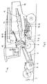
- self-propelled combine harvester 1 passes the crop 3 cut from the cutting unit 2 via a feed screw conveyor 4 and an obliquely upwardly extending intake channel 5 to a threshing device operating on the tangential principle.
- This consists of a threshing cylinder 6 and an associated concave 7.
- a threshing drum 6 and the fixed concave 7 is carried out the expressions of the located in the fruit stands of the crop 3 grains.
- the grains deposited on the concave 7, together with the short straw and the chaff, pass via a conveyor bottom 8 to a cleaning device consisting of a fan 9 and of a top and bottom wire 10; 11 exists.
- a counter-clockwise rotating turning drum 13 is arranged.
- the grains deposited on the straw walkers 12 as well as short straw parts and chaff are fed via a below the straw walker 12 vibrating attached return bottom 14 of the cleaning device.
- the longer straw parts are conveyed across the shaker liners in the direction of the straw discharge 15 and deposited from there on the field soil in the swath or crushed by a straw chopper and then distributed by a distribution device in the field.
- the separated and cleaned in the cleaning device grains are conveyed via an elevator 16 in the grain tank 17.
- the short straw parts and the chaff are guided by the compressed air flow of the blower 9 from the combine harvester 1 for storage on the field soil.
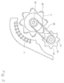
- Threshing device described with the inventive assignment of the turning drum 13 to the threshing cylinder 6 described.
- a continuously variable V-belt drive 18 and an adjoining further V-belt drive 19 driven threshing cylinder shaft 20 a plurality of drum bases 21 are arranged over the width thereof.
- the ribbed threshing bars 22 required for the threshing operation are fastened at a distance from one another by means of screw connections.
- the threshing drum 6 associated with the threshing drum 6 with a closed drum body is provided on its profiled handling with a plurality of longitudinally extending conveyor belts 23.
- the threshing bars 22 of the threshing drum 6 and the conveyor belts 23 of the turning drum 13 are so arranged to each other that they always have in the stripping and turning area an opposing position and the peripheral speeds of the threshing cylinder 6 and the turning drum 13 are synchronized with each other.
- the drive of the threshing drum 6 and the turning drum 13 is preferably two separate, via a Frequency converter controllable electric motors.
- a synchronous peripheral speed of the threshing drum 6 and of this downstream turning drum 13 can be reached by the number of conveyor bars 23 corresponding to the half-integer or integral multiple of the number of threshing bars 22.
- the drive of the threshing drum 6 downstream turning drum 13 in the ratio 1: 1 provided that the diameter of the circular path on which the strips 22, 23 of the threshing cylinder 6 and the downstream turning drum 13, match.
- the speed of the threshing drum 6 and the downstream turning drum 13 must be adjusted in accordance with the reciprocal ratio. This could be realized in a particularly simple manner when using individual motor drives.
Landscapes
- Life Sciences & Earth Sciences (AREA)
- Environmental Sciences (AREA)
- Threshing Machine Elements (AREA)
Abstract
Description
Die Erfindung bezieht sich auf eine Drescheinrichtung für Mähdrescher mit einer Dreschtrommel, einem zugeordneten Dreschkorb und mindestens einer der Dreschtrommel nachgeordneten Trommel, nach dem Oberbegriff des Patentanspruches 1.The invention relates to a threshing device for combine harvester with a threshing drum, an associated concave and at least one downstream of the threshing drum, according to the preamble of claim 1.
An bekannten Ein- und Mehrtrommeldrescheinrichtungen von Mähdreschern sind der Dreschtrommel stets Wendetrommeln und/oder Abscheidetrommeln nachgeordnet, die das ausgedroschene Erntegut zu den Restkornabscheidevorrichtungen in Form von Strohschüttlern oder rotierenden Abscheideeinrichungen weiterfördern. Derartige Wendetrommeln und/oder Abscheidetrommeln sind bereits in verschiedenen Ausführungen und Anordnungen bekannt.In known single and multi-drum threshing devices of combine harvesters, the threshing drum is always followed by turning drums and / or separating drums, which further convey the threshed crop to the residual grain separation devices in the form of straw shakers or rotating separating devices. Such turning drums and / or separating drums are already known in various designs and arrangements.
So ist beispielsweise in der
Aus der
Bei beiden bekannten Antriebsvarianten ist jedoch keine bestimmte Lagepositionierung der Dreschtrommel und der Wendetrommel zueinander weder vorgesehen und aufgrund der konstruktiven Antriebsausführung auch nicht möglich. Dies hat zur Folge, dass beispielsweise bei einem Gegenüberstand einer am Umfang der Wendetrommel angeordneten Förderleiste vom Zwischenraum zweier benachbarter Dreschleisten der Dreschtrommel, die Wendetrommelleiste Erntegut in den Zwischenraum zwischen den Dreschleisten drückt und dadurch das Erntegut nur ungenügend abgestreift wird und oberhalb der Dreschtrommel in einen Umlauf gelangt. Auch wenn eine Dreschleiste gegenüber dem Zwischenraum zwischen zwei benachbarten Förderleisten der Wendetrommel steht, drückt die Dreschleiste der Dreschtrommel Erntegut in den Zwischenraum zwischen zwei benachbarten Förderleisten der Wendetrommelleisten. Aufgrund des sehr großen Spaltes zwischen einer Dreschleiste und der Wendetrommel wird das Erntegut nur unvollständig abgegeben und gelangt dadurch teilweise oberhalb der Dreschtrommel in den Umlauf.In both known drive variants, however, no specific positional positioning of the threshing drum and the turning drum is neither provided to one another nor due to the constructive drive design also not possible. This has the consequence that, for example, in a counter-projection of a arranged on the circumference of the turning drum conveyor bar from the space between two adjacent Dreschleisten the threshing drum, the turning drum bar crop pressed into the space between the Dreschleisten and thereby the crop is stripped only insufficient and passes above the threshing drum in a circulation. Even if a threshing bar opposite the gap between two adjacent conveyor bars of the beater, the threshing of the threshing drum presses crop in the space between two adjacent conveyor bars of the turning drums. Due to the very large gap between a threshing bar and the turning drum, the crop is delivered only incomplete and thus passes partially above the threshing drum in circulation.
In beiden vorstehend genannten Positionen führt dies zu einer Beeinträchtigung des Dresch- und Fördervorganges und damit zu einer Leistungsverringerung des Mähdreschers.In both above-mentioned positions, this leads to an impairment of the threshing and conveying process and thus to a reduction in performance of the combine harvester.
Der Erfindung liegt die Aufgabe zugrunde, durch eine vorteilhafte Zuordnung einer der Dreschtrommel nachgeordneten Trommel zu der Dreschtrommel eine Optimierung des Dresch- und Fördervorganges für das Erntegut zu erreichen.The invention has for its object to achieve by an advantageous assignment of the threshing drum downstream drum to the threshing drum to optimize the threshing and conveying process for the crop.
Diese Aufgabe wird durch die im Patentanspruch 1 genannten kennzeichnenden Merkmale gelöst.This object is achieved by the characterizing features mentioned in claim 1.
Weitere vorteilhafte Ausführungen des Erfindungsgegenstandes ergeben sich aus den nachgeordneten Ansprüchen.Further advantageous embodiments of the subject invention will become apparent from the subordinate claims.
Gemäß Anspruch 1 wird vorgeschlagen, dass die Umfangsgeschwindigkeiten benachbarter Trommeln zueinander so synchronisiert sind, dass die Leisten einander benachbarter Trommeln im Wende- und Abstreifbereich eine stets zueinander gegenüberstehenden beziehungsweise eine geringfügig davon abweichende vorbeziehungsweise nacheilende Position aufweisen. Die erfindungsgemäße Zuordnung der Leisten einander benachbarter Trommeln ermöglicht ein weitgehendes Abstreifen des Erntegutes von den Leisten und ein störungsfreies Weiterfördern zu den nachgeordneten Restkornabscheidevorrichtungen. Im Wirkungsbereich der Dreschtrommel wird dadurch die Erntegutmitnahme und dessen Verlauf um die Dreschtrommel sowie der dadurch verursachte Körnerbruch wesentlich reduziert beziehungsweise völlig vermieden. Die Anwendung der Erfindung ist sowohl an Eintrommel- als auch an Mehrtrommeldrescheinrichtungen mit nachgeordneten Strohschüttlern oder rotierenden Restkornabscheidevorrichtungen möglich.According to claim 1, it is proposed that the circumferential speeds of adjacent drums are synchronized with one another in such a way that the strips of adjacent drums in the turning and wiping region always have a position that is opposite or slightly different from each other. The assignment of the strips of adjacent drums according to the invention allows a substantial stripping of the crop from the strips and a trouble-free forwarding to the downstream Restkornabscheidevorrichtungen. In the range of action of the threshing drum, thereby the Erntegutmitnahme and its course to the Dreschtrommel and the resulting grain breakage significantly reduced or completely avoided. The application of the invention is possible both on single-drum and multi-drum threshing devices with downstream straw walkers or rotating residual grain separation devices.
Vorteilhafterweise kann Position der Leisten (22, 23) der benachbarten Trommeln zueinander in einem Bereich von ca. +/- 10% vor- beziehungsweise nacheilend einstellbar sein.Advantageously, the position of the strips (22, 23) of the adjacent drums can be adjusted to one another in a range of approximately +/- 10% in advance or in a trailing manner.
Insbesondere kann zwischen den benachbarten Trommeln eine mechanische, formschlüssige Antriebsverbindung angeordnet sein. Dies dient dazu, einen schlupffreien Antrieb der benachbarten Trommeln zu gewährleisten, um eine synchrone Umfangsgeschwindigkeit einhalten zu können.In particular, a mechanical, positive drive connection can be arranged between the adjacent drums. This serves to ensure a slip-free drive of the adjacent drums in order to be able to maintain a synchronous peripheral speed.
Vorzugsweise kann als formschlüssige Antriebsverbindung zwischen den benachbarten Trommeln ein Zahnriemen oder ein Getriebe angeordnet sein.Preferably, a toothed belt or a gear can be arranged as a positive drive connection between the adjacent drums.
Alternativ können die benachbarten Trommeln durch zwei separate, über einen Frequenzumrichter regelbare Elektromotoren antreibbar sein. Diese Antriebsvariante ermöglicht eine einfache Anpassung der jeweiligen Umfangsgeschwindigkeit der benachbarten Trommeln an die verschiedenen Ausführungen von Dreschtrommel und diesen nachgeordneten Trommeln, wie einer Wendetrommel und/oder einer Abscheidetrommel, beispielsweise hinsichtlich ihrer voneinander abweichenden Durchmesser.Alternatively, the adjacent drums can be driven by two separate, controllable by a frequency converter electric motors. This drive variant allows a simple adaptation of the respective peripheral speed of the adjacent drums to the different versions of threshing drum and these downstream drums, such as a turning drum and / or a separating drum, for example, with respect to their divergent diameter.
Gemäß einer weiteren Ausführungsform können die benachbarten Trommeln hydraulisch antreibbar sein.According to a further embodiment, the adjacent drums can be hydraulically driven.
Des Weiteren kann die Anzahl der Leisten der mindestens einen der Dreschtrommel nachgeordneten Trommel dem halbzahligen oder ganzzahligen Vielfachen der Anzahl der Dreschleisten der Dreschtrommel entsprechen. Insbesondere bei einem ganzzahligen Vielfachen der Anzahl der Leisten ließe sich eine Reduzierung der Drehzahl der nachgeordneten Trommel erreichen, wodurch der Bruchkornanteil reduziert würde. Hingegen ließe sich gleichem Außenumfang der Dreschtrommel und der nachgeordneten Trommel sowie gleicher Leistenanzahl ein übersetzungsfreier Antrieb realisieren, was den zusätzlichen Vorteil hätte, dass auf Grund der Reduzierung der Drehzahl der mindestens einen nachgeordneten Trommel gegenüber einer mit einem Übersetzungsverhältnis angetriebenen, nachgeordneten Trommel, die bei gleicher Anzahl von Leisten eine höhere Drehzahl als die Dreschtrommel aufweist, ebenfalls ein positiver Einfluss auf den Bruchkornanteil erreichen lässt. Gleiches gilt für die Anordnung einer Wendetrommel und einer Abscheidetrommel, die der Dreschtrommel nachgeordnet sein können.Furthermore, the number of strips of the at least one drum arranged downstream of the threshing drum can correspond to the half-integer or integer multiple of the number of threshing strips of the threshing drum. In particular, with an integer multiple of the number of strips, a reduction in the rotational speed of the downstream drum could be achieved, whereby the fraction of broken grains would be reduced. On the other hand, the same outer circumference of the threshing drum could be used and the downstream drum and the same number of strips realize a translation-free drive, which would have the additional advantage that due to the reduction of the speed of the at least one downstream drum over a driven with a gear ratio, downstream drum, the same number of strips a higher speed than the threshing drum also has a positive influence on the fraction of broken grains. The same applies to the arrangement of a turning drum and a separating drum, which may be arranged downstream of the threshing drum.
Die Erfindung wird nachstehend an einem Ausführungsbeispiel näher erläutert.The invention will be explained in more detail using an exemplary embodiment.
In den zugehörigen Zeichnungen zeigen:
- Fig. 1
- eine schematische Längsschnittdarstellung eines Mähdreschers;
- Fig. 2.
- einen Querschnitt durch die Drescheinrichtung;
- Fig. 3.
- eine Draufsicht auf die Dreschtrommel und die Wendetrommel mit den zugehörigen Antrieben.
- Fig. 1
- a schematic longitudinal sectional view of a combine harvester;
- Fig. 2.
- a cross section through the threshing device;
- Fig. 3.
- a plan view of the threshing drum and the beater with the associated drives.
Bei dem in der
Im Folgenden wird die in der
Durch diese Zuordnung wird ein vorteilhafter und störungsfreier Erntegutfluss zwischen der Dreschtrommel 6 und den Strohschüttlern 12 erreicht. Da die genaue Positionseinstellung der Dreschleisten 22 zu den Förderleisten 23 zur Gewährleistung der vollen Funktionsfähigkeit während der gesamten Betriebszeit aufrecht erhalten bleiben muss und nicht verändert werden darf, ist zwischen der Dreschtrommel 6 und der Wendetrommel 13 ein schlupffreier Antrieb erforderlich. Dies wird durch eine mechanische, formschlüssige Antriebsverbindung 25, beispielsweise durch einen Zahnriemen oder durch eine Getriebeverbindung erreicht. Nach einer weiteren Ausführungsvariante erfolgt der Antrieb der Dreschtrommel 6 und der Wendetrommel 13 jeweils einzel motorisch über synchron gesteuerte Elektromotoren. Sofern eine funktionsbedingte geringfügige vor- oder nacheilende Position der Förderleisten 23 der Wendetrommel 13 gegenüber den Dreschleisten 22 der Dreschtrommel 6 von ca. +/- 10% erforderlich ist, erfolgt der Antrieb der Dreschtrommel 6 und der Wendetrommel 13 vorzugsweise über zwei separate, über einen Frequenzumrichter regelbare Elektromotoren.By this assignment, an advantageous and trouble-free Erntegutfluss between the
In einfacher Weise lässt sich eine synchrone Umfangsgeschwindigkeit der Dreschtrommel 6 und der dieser nachgeordneten Wendetrommel 13 ereichen, indem die Anzahl der Förderleisten 23 dem halbzahligen oder ganzzahligen Vielfachen der Anzahl der Dreschleisten 22 entspricht. Bei gleicher Anzahl von Dreschleisten 22 und Förderleisten 23, wie in
In der oben beschrieben Weise lassen sich auch mehrere der Dreschtrommel 6 nachgeordnete Trommeln antreiben, deren Umfangsgeschwindigkeiten zueinander synchronisiert werden sollen, beispielsweise bei einer Anordnung von einer Dreschtrommel, einer Wendetrommel und einer der Wendetrommel nachgeordneten Abscheidetrommel. Für diese Konstellation eines Mehrtrommeldreschwerkes wird durch die Synchronisation der Umfangsgeschwindigkeiten in der Weise, dass die Leisten einander benachbarter Trommeln, Dreschtrommel 6 und Wendetrommel 13 sowie Wendetrommel 13 und eine dieser nachgeordneten Abscheidetrommel, im Wende- und Abstreifbereich eine stets zueinander gegenüberstehenden beziehungsweise eine geringfügig davon abweichende vor- beziehungsweise nacheilende Position aufweisen, der Anteil des oberhalb der Dreschtrommel in den Umlauf zurückgeführten Erntegutes reduziert.In the manner described above, it is also possible to drive a plurality of
- 11
- MähdrescherHarvester
- 22
- Schneidwerkcutting
- 33
- Erntegutcrop
- 44
- EinzugsförderschneckeFeed auger
- 55
- Einzugskanalfeeder housing
- 66
- Dreschtrommelthreshing
- 77
- Dreschkorbconcave
- 88th
- FörderbodenLive floor
- 99
- Gebläsefan
- 1010
- Obersiebtop wire
- 1111
- Untersiebbottom wire
- 1212
- Strohschüttlerbeater
- 1313
- Wendetrommelbeater
- 1414
- RücklaufbodenReturn pan
- 1515
- Strohauslaufstraw outlet
- 1616
- ElevatorElevator
- 1717
- Korntankgrain tank
- 1818
- stufenloser Keilriemenantriebstepless V-belt drive
- 1919
- KeilriemenantriebV-belt drive
- 2020
- DreschtrommelwelleDreschtrommelwelle
- 2121
- Trommelbödencylinder ends
- 2222
- Dreschleistenthreshing
- 2323
- Förderleistenconveying strips
- 2424
- Zwischenräumeinterspaces
- 2525
- Antriebsverbindungdrive connection
Claims (7)
Applications Claiming Priority (1)
| Application Number | Priority Date | Filing Date | Title |
|---|---|---|---|
| DE102010016670A DE102010016670A1 (en) | 2010-04-28 | 2010-04-28 | Threshing device for combine harvester |
Publications (3)
| Publication Number | Publication Date |
|---|---|
| EP2382857A2 true EP2382857A2 (en) | 2011-11-02 |
| EP2382857A3 EP2382857A3 (en) | 2013-07-03 |
| EP2382857B1 EP2382857B1 (en) | 2014-06-18 |
Family
ID=44280910
Family Applications (1)
| Application Number | Title | Priority Date | Filing Date |
|---|---|---|---|
| EP11155745.0A Active EP2382857B1 (en) | 2010-04-28 | 2011-02-24 | Thresher device for a combine harvester |
Country Status (4)
| Country | Link |
|---|---|
| US (1) | US8231447B2 (en) |
| EP (1) | EP2382857B1 (en) |
| DE (1) | DE102010016670A1 (en) |
| RU (1) | RU2553838C2 (en) |
Cited By (2)
| Publication number | Priority date | Publication date | Assignee | Title |
|---|---|---|---|---|
| CN103609250A (en) * | 2013-11-26 | 2014-03-05 | 浙江亿森机械有限公司 | Threshing structure of L-shaped horizontal and longitudinal axial flow full-feeding combine harvester |
| CN110859090A (en) * | 2019-12-14 | 2020-03-06 | 芜湖市创源新材料有限公司 | Cylinder type threshing device |
Families Citing this family (1)
| Publication number | Priority date | Publication date | Assignee | Title |
|---|---|---|---|---|
| US8651927B1 (en) | 2012-09-13 | 2014-02-18 | Cnh America Llc | Combine harvester sieve assembly with an integrated air cleaning system |
Citations (2)
| Publication number | Priority date | Publication date | Assignee | Title |
|---|---|---|---|---|
| DE19631866A1 (en) | 1996-08-07 | 1998-02-12 | Same Spa | Threshing device for combine harvesters |
| DE102007006926A1 (en) | 2007-02-05 | 2008-08-14 | Same Deutz- Fahr Deutschland Gmbh | Harvester e.g. for threshing device, has thresher cylinder, rotating drum and drive for drums and drive of first cylinder is driven, which in turn drives drum |
Family Cites Families (26)
| Publication number | Priority date | Publication date | Assignee | Title |
|---|---|---|---|---|
| US759391A (en) * | 1903-03-23 | 1904-05-10 | James Mcgrane | Threshing-machine. |
| US3593719A (en) * | 1969-04-02 | 1971-07-20 | Massey Ferguson Ind Ltd | Combine with three-stage separation |
| DE2133448C3 (en) * | 1970-07-09 | 1974-09-12 | Agrostroj Prostejov, N.P., Prostejov (Tschechoslowakei) | Device for driving a threshing and guide drum, especially in combine harvesters |
| DE2317048A1 (en) * | 1973-04-05 | 1974-10-17 | Helwig Schmitt | HARVESTER |
| DE2923022A1 (en) * | 1979-06-07 | 1981-02-05 | Claas Ohg | SCHUETTLERLOS SELF-DRIVING COMBINATION |
| US4312366A (en) * | 1979-11-14 | 1982-01-26 | Sperry Corporation | Combine harvester |
| DE3114382C2 (en) * | 1981-04-09 | 1986-11-20 | Claas Ohg, 4834 Harsewinkel | Shakerless self-propelled combine harvester |
| CA1209621A (en) * | 1983-07-11 | 1986-08-12 | Jacques Laliberte | Forage blower |
| US4802496A (en) * | 1987-05-19 | 1989-02-07 | Deere & Company | Agricultural concave adjustment means |
| SU1482590A1 (en) * | 1987-10-27 | 1989-05-30 | Литовская сельскохозяйственная академия | Grain combine harvester |
| SU1544267A1 (en) * | 1988-04-01 | 1990-02-23 | Московский институт инженеров сельскохозяйственного производства им.В.П.Горячкина | Threshing-separating device |
| FR2658983A1 (en) * | 1990-03-02 | 1991-09-06 | Bourdichon Alain | Device for separating the grain using forced passage in a combine harvester |
| FI85561C (en) * | 1990-06-29 | 1992-05-11 | Larox Ag | Procedure for controlling pressure filter |
| DE4023720A1 (en) * | 1990-07-26 | 1992-01-30 | Claas Ohg | SELF-DRIVING COMBINATION |
| US5395287A (en) * | 1993-05-10 | 1995-03-07 | Deere & Company | Multi-profile transition element |
| DE19520463A1 (en) * | 1995-06-03 | 1996-12-05 | Claas Ohg | Self-propelled combine with adjustable concave |
| DE19709398A1 (en) * | 1997-03-07 | 1998-09-10 | Deere & Co | Good processing device |
| US5899121A (en) * | 1997-12-29 | 1999-05-04 | Eaton Corporation | Fluid biased transmission range valve |
| DE19844894A1 (en) * | 1998-09-30 | 2000-04-06 | Claas Selbstfahr Erntemasch | Adjustment device of an agricultural harvester |
| DE10034784A1 (en) * | 2000-07-18 | 2002-02-14 | Deere & Co | Harvesting machine with an electric motor-driven crop conveying and / or crop processing device |
| US6823954B2 (en) * | 2001-05-18 | 2004-11-30 | Honda Giken Kogyo Kabushiki Kaisha | Control system for hybrid vehicle |
| RU2208928C2 (en) * | 2001-08-13 | 2003-07-27 | Красноярский научно-исследовательский институт сельского хозяйства | Grain combine |
| GB0214114D0 (en) * | 2002-06-20 | 2002-07-31 | Cnh Belgium Nv | Threshing machinery concave arrangements |
| US7797916B2 (en) * | 2005-01-25 | 2010-09-21 | Randy Thompson | Systems and methods for harvesting cotton |
| DE202008004985U1 (en) * | 2008-04-10 | 2009-08-13 | Liebherr-Werk Biberach Gmbh | winch |
| US7726108B1 (en) * | 2009-01-14 | 2010-06-01 | Agco Corporation | Wide cut rotary harvester having cut crop feeder mechanism |
-
2010
- 2010-04-28 DE DE102010016670A patent/DE102010016670A1/en not_active Withdrawn
-
2011
- 2011-02-24 EP EP11155745.0A patent/EP2382857B1/en active Active
- 2011-04-20 US US13/090,365 patent/US8231447B2/en active Active
- 2011-04-25 RU RU2011115984/13A patent/RU2553838C2/en active
Patent Citations (2)
| Publication number | Priority date | Publication date | Assignee | Title |
|---|---|---|---|---|
| DE19631866A1 (en) | 1996-08-07 | 1998-02-12 | Same Spa | Threshing device for combine harvesters |
| DE102007006926A1 (en) | 2007-02-05 | 2008-08-14 | Same Deutz- Fahr Deutschland Gmbh | Harvester e.g. for threshing device, has thresher cylinder, rotating drum and drive for drums and drive of first cylinder is driven, which in turn drives drum |
Cited By (2)
| Publication number | Priority date | Publication date | Assignee | Title |
|---|---|---|---|---|
| CN103609250A (en) * | 2013-11-26 | 2014-03-05 | 浙江亿森机械有限公司 | Threshing structure of L-shaped horizontal and longitudinal axial flow full-feeding combine harvester |
| CN110859090A (en) * | 2019-12-14 | 2020-03-06 | 芜湖市创源新材料有限公司 | Cylinder type threshing device |
Also Published As
| Publication number | Publication date |
|---|---|
| US8231447B2 (en) | 2012-07-31 |
| EP2382857A3 (en) | 2013-07-03 |
| RU2011115984A (en) | 2012-10-27 |
| EP2382857B1 (en) | 2014-06-18 |
| RU2553838C2 (en) | 2015-06-20 |
| DE102010016670A1 (en) | 2011-11-03 |
| US20110269515A1 (en) | 2011-11-03 |
Similar Documents
| Publication | Publication Date | Title |
|---|---|---|
| EP2965614B1 (en) | Entry section head housing | |
| DE2000553C3 (en) | ||
| DE2462568C2 (en) | Harvester | |
| EP0591688B1 (en) | Self-propelled combine | |
| EP0522268B1 (en) | Axial separator | |
| EP0522267B1 (en) | Axial separator | |
| EP0521280B1 (en) | Axial separator | |
| EP2796032B1 (en) | Combine harvester with a cleaning device | |
| EP0514820B1 (en) | Tooth, holder, tooth attachment device and axial separator | |
| EP2327290A2 (en) | Concave for a tangential threshing unit | |
| DE102013226436B4 (en) | Feederhouse for a combine harvester | |
| EP2481277B1 (en) | Thresher system of a combined harvester | |
| DE3125659C2 (en) | ||
| EP2382857B1 (en) | Thresher device for a combine harvester | |
| EP3369301B1 (en) | Agricultural harvester | |
| EP3420803A1 (en) | Threshing or separating concave for grain harvesting | |
| EP2036425B1 (en) | Concave assembly for a combine harvester | |
| DE2413975C2 (en) | Grain cutter, e.g. for combine harvesters | |
| EP3763198B1 (en) | Threshing drum of a threshing device for a combine | |
| EP2805602A2 (en) | Combine harvester | |
| DE102012106338A1 (en) | Dreschtrommel and equipped with such a threshing drum mobile threshing | |
| DE102009026870A1 (en) | Straw walker arrangement for combine utilized for harvesting grain fruit, has drive provided for increasing or decreasing rotating speed of crankshaft following one on other, where drive rotates crankshaft about axis | |
| DE3245146C2 (en) | Self-propelled combine harvester based on the axial flow system | |
| EP4230024A1 (en) | Self-propelled combine harvester |
Legal Events
| Date | Code | Title | Description |
|---|---|---|---|
| AK | Designated contracting states |
Kind code of ref document: A2 Designated state(s): AL AT BE BG CH CY CZ DE DK EE ES FI FR GB GR HR HU IE IS IT LI LT LU LV MC MK MT NL NO PL PT RO RS SE SI SK SM TR |
|
| AX | Request for extension of the european patent |
Extension state: BA ME |
|
| PUAI | Public reference made under article 153(3) epc to a published international application that has entered the european phase |
Free format text: ORIGINAL CODE: 0009012 |
|
| PUAL | Search report despatched |
Free format text: ORIGINAL CODE: 0009013 |
|
| AK | Designated contracting states |
Kind code of ref document: A3 Designated state(s): AL AT BE BG CH CY CZ DE DK EE ES FI FR GB GR HR HU IE IS IT LI LT LU LV MC MK MT NL NO PL PT RO RS SE SI SK SM TR |
|
| AX | Request for extension of the european patent |
Extension state: BA ME |
|
| RIC1 | Information provided on ipc code assigned before grant |
Ipc: A01F 12/18 20060101AFI20130528BHEP Ipc: A01F 12/56 20060101ALI20130528BHEP |
|
| 17P | Request for examination filed |
Effective date: 20140103 |
|
| RBV | Designated contracting states (corrected) |
Designated state(s): AL AT BE BG CH CY CZ DE DK EE ES FI FR GB GR HR HU IE IS IT LI LT LU LV MC MK MT NL NO PL PT RO RS SE SI SK SM TR |
|
| GRAP | Despatch of communication of intention to grant a patent |
Free format text: ORIGINAL CODE: EPIDOSNIGR1 |
|
| INTG | Intention to grant announced |
Effective date: 20140310 |
|
| GRAS | Grant fee paid |
Free format text: ORIGINAL CODE: EPIDOSNIGR3 |
|
| GRAA | (expected) grant |
Free format text: ORIGINAL CODE: 0009210 |
|
| AK | Designated contracting states |
Kind code of ref document: B1 Designated state(s): AL AT BE BG CH CY CZ DE DK EE ES FI FR GB GR HR HU IE IS IT LI LT LU LV MC MK MT NL NO PL PT RO RS SE SI SK SM TR |
|
| REG | Reference to a national code |
Ref country code: GB Ref legal event code: FG4D Free format text: NOT ENGLISH |
|
| REG | Reference to a national code |
Ref country code: CH Ref legal event code: EP |
|
| REG | Reference to a national code |
Ref country code: AT Ref legal event code: REF Ref document number: 672785 Country of ref document: AT Kind code of ref document: T Effective date: 20140715 |
|
| REG | Reference to a national code |
Ref country code: IE Ref legal event code: FG4D Free format text: LANGUAGE OF EP DOCUMENT: GERMAN |
|
| REG | Reference to a national code |
Ref country code: DE Ref legal event code: R096 Ref document number: 502011003414 Country of ref document: DE Effective date: 20140731 |
|
| PG25 | Lapsed in a contracting state [announced via postgrant information from national office to epo] |
Ref country code: GR Free format text: LAPSE BECAUSE OF FAILURE TO SUBMIT A TRANSLATION OF THE DESCRIPTION OR TO PAY THE FEE WITHIN THE PRESCRIBED TIME-LIMIT Effective date: 20140919 Ref country code: LT Free format text: LAPSE BECAUSE OF FAILURE TO SUBMIT A TRANSLATION OF THE DESCRIPTION OR TO PAY THE FEE WITHIN THE PRESCRIBED TIME-LIMIT Effective date: 20140618 Ref country code: NO Free format text: LAPSE BECAUSE OF FAILURE TO SUBMIT A TRANSLATION OF THE DESCRIPTION OR TO PAY THE FEE WITHIN THE PRESCRIBED TIME-LIMIT Effective date: 20140918 Ref country code: CY Free format text: LAPSE BECAUSE OF FAILURE TO SUBMIT A TRANSLATION OF THE DESCRIPTION OR TO PAY THE FEE WITHIN THE PRESCRIBED TIME-LIMIT Effective date: 20140618 Ref country code: FI Free format text: LAPSE BECAUSE OF FAILURE TO SUBMIT A TRANSLATION OF THE DESCRIPTION OR TO PAY THE FEE WITHIN THE PRESCRIBED TIME-LIMIT Effective date: 20140618 |
|
| REG | Reference to a national code |
Ref country code: NL Ref legal event code: VDEP Effective date: 20140618 |
|
| REG | Reference to a national code |
Ref country code: LT Ref legal event code: MG4D |
|
| PG25 | Lapsed in a contracting state [announced via postgrant information from national office to epo] |
Ref country code: HR Free format text: LAPSE BECAUSE OF FAILURE TO SUBMIT A TRANSLATION OF THE DESCRIPTION OR TO PAY THE FEE WITHIN THE PRESCRIBED TIME-LIMIT Effective date: 20140618 Ref country code: SE Free format text: LAPSE BECAUSE OF FAILURE TO SUBMIT A TRANSLATION OF THE DESCRIPTION OR TO PAY THE FEE WITHIN THE PRESCRIBED TIME-LIMIT Effective date: 20140618 Ref country code: LV Free format text: LAPSE BECAUSE OF FAILURE TO SUBMIT A TRANSLATION OF THE DESCRIPTION OR TO PAY THE FEE WITHIN THE PRESCRIBED TIME-LIMIT Effective date: 20140618 Ref country code: RS Free format text: LAPSE BECAUSE OF FAILURE TO SUBMIT A TRANSLATION OF THE DESCRIPTION OR TO PAY THE FEE WITHIN THE PRESCRIBED TIME-LIMIT Effective date: 20140618 |
|
| PG25 | Lapsed in a contracting state [announced via postgrant information from national office to epo] |
Ref country code: ES Free format text: LAPSE BECAUSE OF FAILURE TO SUBMIT A TRANSLATION OF THE DESCRIPTION OR TO PAY THE FEE WITHIN THE PRESCRIBED TIME-LIMIT Effective date: 20140618 Ref country code: SK Free format text: LAPSE BECAUSE OF FAILURE TO SUBMIT A TRANSLATION OF THE DESCRIPTION OR TO PAY THE FEE WITHIN THE PRESCRIBED TIME-LIMIT Effective date: 20140618 Ref country code: PT Free format text: LAPSE BECAUSE OF FAILURE TO SUBMIT A TRANSLATION OF THE DESCRIPTION OR TO PAY THE FEE WITHIN THE PRESCRIBED TIME-LIMIT Effective date: 20141020 Ref country code: EE Free format text: LAPSE BECAUSE OF FAILURE TO SUBMIT A TRANSLATION OF THE DESCRIPTION OR TO PAY THE FEE WITHIN THE PRESCRIBED TIME-LIMIT Effective date: 20140618 Ref country code: RO Free format text: LAPSE BECAUSE OF FAILURE TO SUBMIT A TRANSLATION OF THE DESCRIPTION OR TO PAY THE FEE WITHIN THE PRESCRIBED TIME-LIMIT Effective date: 20140618 Ref country code: CZ Free format text: LAPSE BECAUSE OF FAILURE TO SUBMIT A TRANSLATION OF THE DESCRIPTION OR TO PAY THE FEE WITHIN THE PRESCRIBED TIME-LIMIT Effective date: 20140618 |
|
| PG25 | Lapsed in a contracting state [announced via postgrant information from national office to epo] |
Ref country code: PL Free format text: LAPSE BECAUSE OF FAILURE TO SUBMIT A TRANSLATION OF THE DESCRIPTION OR TO PAY THE FEE WITHIN THE PRESCRIBED TIME-LIMIT Effective date: 20140618 Ref country code: NL Free format text: LAPSE BECAUSE OF FAILURE TO SUBMIT A TRANSLATION OF THE DESCRIPTION OR TO PAY THE FEE WITHIN THE PRESCRIBED TIME-LIMIT Effective date: 20140618 Ref country code: IS Free format text: LAPSE BECAUSE OF FAILURE TO SUBMIT A TRANSLATION OF THE DESCRIPTION OR TO PAY THE FEE WITHIN THE PRESCRIBED TIME-LIMIT Effective date: 20141018 |
|
| REG | Reference to a national code |
Ref country code: DE Ref legal event code: R097 Ref document number: 502011003414 Country of ref document: DE |
|
| PLBE | No opposition filed within time limit |
Free format text: ORIGINAL CODE: 0009261 |
|
| STAA | Information on the status of an ep patent application or granted ep patent |
Free format text: STATUS: NO OPPOSITION FILED WITHIN TIME LIMIT |
|
| PG25 | Lapsed in a contracting state [announced via postgrant information from national office to epo] |
Ref country code: DK Free format text: LAPSE BECAUSE OF FAILURE TO SUBMIT A TRANSLATION OF THE DESCRIPTION OR TO PAY THE FEE WITHIN THE PRESCRIBED TIME-LIMIT Effective date: 20140618 |
|
| 26N | No opposition filed |
Effective date: 20150319 |
|
| PG25 | Lapsed in a contracting state [announced via postgrant information from national office to epo] |
Ref country code: SI Free format text: LAPSE BECAUSE OF FAILURE TO SUBMIT A TRANSLATION OF THE DESCRIPTION OR TO PAY THE FEE WITHIN THE PRESCRIBED TIME-LIMIT Effective date: 20140618 |
|
| PG25 | Lapsed in a contracting state [announced via postgrant information from national office to epo] |
Ref country code: LU Free format text: LAPSE BECAUSE OF FAILURE TO SUBMIT A TRANSLATION OF THE DESCRIPTION OR TO PAY THE FEE WITHIN THE PRESCRIBED TIME-LIMIT Effective date: 20150224 |
|
| REG | Reference to a national code |
Ref country code: CH Ref legal event code: PL |
|
| GBPC | Gb: european patent ceased through non-payment of renewal fee |
Effective date: 20150224 |
|
| PG25 | Lapsed in a contracting state [announced via postgrant information from national office to epo] |
Ref country code: CH Free format text: LAPSE BECAUSE OF NON-PAYMENT OF DUE FEES Effective date: 20150228 Ref country code: MC Free format text: LAPSE BECAUSE OF FAILURE TO SUBMIT A TRANSLATION OF THE DESCRIPTION OR TO PAY THE FEE WITHIN THE PRESCRIBED TIME-LIMIT Effective date: 20140618 Ref country code: LI Free format text: LAPSE BECAUSE OF NON-PAYMENT OF DUE FEES Effective date: 20150228 |
|
| REG | Reference to a national code |
Ref country code: IE Ref legal event code: MM4A |
|
| REG | Reference to a national code |
Ref country code: FR Ref legal event code: ST Effective date: 20151030 |
|
| PG25 | Lapsed in a contracting state [announced via postgrant information from national office to epo] |
Ref country code: IE Free format text: LAPSE BECAUSE OF NON-PAYMENT OF DUE FEES Effective date: 20150224 Ref country code: GB Free format text: LAPSE BECAUSE OF NON-PAYMENT OF DUE FEES Effective date: 20150224 |
|
| PG25 | Lapsed in a contracting state [announced via postgrant information from national office to epo] |
Ref country code: FR Free format text: LAPSE BECAUSE OF NON-PAYMENT OF DUE FEES Effective date: 20150302 |
|
| PG25 | Lapsed in a contracting state [announced via postgrant information from national office to epo] |
Ref country code: MT Free format text: LAPSE BECAUSE OF FAILURE TO SUBMIT A TRANSLATION OF THE DESCRIPTION OR TO PAY THE FEE WITHIN THE PRESCRIBED TIME-LIMIT Effective date: 20140618 |
|
| REG | Reference to a national code |
Ref country code: AT Ref legal event code: MM01 Ref document number: 672785 Country of ref document: AT Kind code of ref document: T Effective date: 20160224 |
|
| PG25 | Lapsed in a contracting state [announced via postgrant information from national office to epo] |
Ref country code: BG Free format text: LAPSE BECAUSE OF FAILURE TO SUBMIT A TRANSLATION OF THE DESCRIPTION OR TO PAY THE FEE WITHIN THE PRESCRIBED TIME-LIMIT Effective date: 20140618 Ref country code: SM Free format text: LAPSE BECAUSE OF FAILURE TO SUBMIT A TRANSLATION OF THE DESCRIPTION OR TO PAY THE FEE WITHIN THE PRESCRIBED TIME-LIMIT Effective date: 20140618 Ref country code: AT Free format text: LAPSE BECAUSE OF NON-PAYMENT OF DUE FEES Effective date: 20160224 Ref country code: HU Free format text: LAPSE BECAUSE OF FAILURE TO SUBMIT A TRANSLATION OF THE DESCRIPTION OR TO PAY THE FEE WITHIN THE PRESCRIBED TIME-LIMIT; INVALID AB INITIO Effective date: 20110224 |
|
| PG25 | Lapsed in a contracting state [announced via postgrant information from national office to epo] |
Ref country code: TR Free format text: LAPSE BECAUSE OF FAILURE TO SUBMIT A TRANSLATION OF THE DESCRIPTION OR TO PAY THE FEE WITHIN THE PRESCRIBED TIME-LIMIT Effective date: 20140618 |
|
| PG25 | Lapsed in a contracting state [announced via postgrant information from national office to epo] |
Ref country code: MK Free format text: LAPSE BECAUSE OF FAILURE TO SUBMIT A TRANSLATION OF THE DESCRIPTION OR TO PAY THE FEE WITHIN THE PRESCRIBED TIME-LIMIT Effective date: 20140618 |
|
| PG25 | Lapsed in a contracting state [announced via postgrant information from national office to epo] |
Ref country code: AL Free format text: LAPSE BECAUSE OF FAILURE TO SUBMIT A TRANSLATION OF THE DESCRIPTION OR TO PAY THE FEE WITHIN THE PRESCRIBED TIME-LIMIT Effective date: 20140618 |
|
| PGFP | Annual fee paid to national office [announced via postgrant information from national office to epo] |
Ref country code: IT Payment date: 20230223 Year of fee payment: 13 Ref country code: BE Payment date: 20230216 Year of fee payment: 13 |
|
| P01 | Opt-out of the competence of the unified patent court (upc) registered |
Effective date: 20230515 |
|
| PGFP | Annual fee paid to national office [announced via postgrant information from national office to epo] |
Ref country code: DE Payment date: 20240219 Year of fee payment: 14 |