EP2381512A1 - Cell module - Google Patents
Cell module Download PDFInfo
- Publication number
- EP2381512A1 EP2381512A1 EP10830931A EP10830931A EP2381512A1 EP 2381512 A1 EP2381512 A1 EP 2381512A1 EP 10830931 A EP10830931 A EP 10830931A EP 10830931 A EP10830931 A EP 10830931A EP 2381512 A1 EP2381512 A1 EP 2381512A1
- Authority
- EP
- European Patent Office
- Prior art keywords
- battery
- battery module
- negative electrode
- positive electrode
- conductive strip
- Prior art date
- Legal status (The legal status is an assumption and is not a legal conclusion. Google has not performed a legal analysis and makes no representation as to the accuracy of the status listed.)
- Withdrawn
Links
Images




Classifications
-
- H—ELECTRICITY
- H01—ELECTRIC ELEMENTS
- H01M—PROCESSES OR MEANS, e.g. BATTERIES, FOR THE DIRECT CONVERSION OF CHEMICAL ENERGY INTO ELECTRICAL ENERGY
- H01M50/00—Constructional details or processes of manufacture of the non-active parts of electrochemical cells other than fuel cells, e.g. hybrid cells
- H01M50/50—Current conducting connections for cells or batteries
-
- H—ELECTRICITY
- H01—ELECTRIC ELEMENTS
- H01M—PROCESSES OR MEANS, e.g. BATTERIES, FOR THE DIRECT CONVERSION OF CHEMICAL ENERGY INTO ELECTRICAL ENERGY
- H01M10/00—Secondary cells; Manufacture thereof
- H01M10/42—Methods or arrangements for servicing or maintenance of secondary cells or secondary half-cells
- H01M10/4207—Methods or arrangements for servicing or maintenance of secondary cells or secondary half-cells for several batteries or cells simultaneously or sequentially
-
- H—ELECTRICITY
- H01—ELECTRIC ELEMENTS
- H01M—PROCESSES OR MEANS, e.g. BATTERIES, FOR THE DIRECT CONVERSION OF CHEMICAL ENERGY INTO ELECTRICAL ENERGY
- H01M10/00—Secondary cells; Manufacture thereof
- H01M10/42—Methods or arrangements for servicing or maintenance of secondary cells or secondary half-cells
- H01M10/44—Methods for charging or discharging
- H01M10/441—Methods for charging or discharging for several batteries or cells simultaneously or sequentially
-
- H—ELECTRICITY
- H01—ELECTRIC ELEMENTS
- H01M—PROCESSES OR MEANS, e.g. BATTERIES, FOR THE DIRECT CONVERSION OF CHEMICAL ENERGY INTO ELECTRICAL ENERGY
- H01M50/00—Constructional details or processes of manufacture of the non-active parts of electrochemical cells other than fuel cells, e.g. hybrid cells
- H01M50/20—Mountings; Secondary casings or frames; Racks, modules or packs; Suspension devices; Shock absorbers; Transport or carrying devices; Holders
-
- H—ELECTRICITY
- H01—ELECTRIC ELEMENTS
- H01M—PROCESSES OR MEANS, e.g. BATTERIES, FOR THE DIRECT CONVERSION OF CHEMICAL ENERGY INTO ELECTRICAL ENERGY
- H01M50/00—Constructional details or processes of manufacture of the non-active parts of electrochemical cells other than fuel cells, e.g. hybrid cells
- H01M50/50—Current conducting connections for cells or batteries
- H01M50/502—Interconnectors for connecting terminals of adjacent batteries; Interconnectors for connecting cells outside a battery casing
- H01M50/507—Interconnectors for connecting terminals of adjacent batteries; Interconnectors for connecting cells outside a battery casing comprising an arrangement of two or more busbars within a container structure, e.g. busbar modules
-
- H—ELECTRICITY
- H01—ELECTRIC ELEMENTS
- H01M—PROCESSES OR MEANS, e.g. BATTERIES, FOR THE DIRECT CONVERSION OF CHEMICAL ENERGY INTO ELECTRICAL ENERGY
- H01M50/00—Constructional details or processes of manufacture of the non-active parts of electrochemical cells other than fuel cells, e.g. hybrid cells
- H01M50/50—Current conducting connections for cells or batteries
- H01M50/502—Interconnectors for connecting terminals of adjacent batteries; Interconnectors for connecting cells outside a battery casing
- H01M50/509—Interconnectors for connecting terminals of adjacent batteries; Interconnectors for connecting cells outside a battery casing characterised by the type of connection, e.g. mixed connections
-
- Y—GENERAL TAGGING OF NEW TECHNOLOGICAL DEVELOPMENTS; GENERAL TAGGING OF CROSS-SECTIONAL TECHNOLOGIES SPANNING OVER SEVERAL SECTIONS OF THE IPC; TECHNICAL SUBJECTS COVERED BY FORMER USPC CROSS-REFERENCE ART COLLECTIONS [XRACs] AND DIGESTS
- Y02—TECHNOLOGIES OR APPLICATIONS FOR MITIGATION OR ADAPTATION AGAINST CLIMATE CHANGE
- Y02E—REDUCTION OF GREENHOUSE GAS [GHG] EMISSIONS, RELATED TO ENERGY GENERATION, TRANSMISSION OR DISTRIBUTION
- Y02E60/00—Enabling technologies; Technologies with a potential or indirect contribution to GHG emissions mitigation
- Y02E60/10—Energy storage using batteries
Definitions
- the present invention relates to a battery module comprising a plurality of battery groups being connected in series and each comprising a plurality of battery cells connected in parallel. More specifically, the present invention relates to a battery module formed by connecting battery groups by an improved method.
- Batteries have started to be used as a power source for transportation equipment, machining equipment, power storage equipment and the like, in addition to be used as a driving power source for electric equipment and electronic equipment.
- the batteries used for transportation equipment, machining equipment, and power storage equipment are required to provide an instantaneous or continuous high output.
- a battery group formed by connecting a plurality of battery cells, or a battery module formed by further connecting these battery groups satisfies such a requirement.
- Patent Document 1 discloses a battery group comprising a plurality of battery cells connected in parallel, from which electric power is extracted through lead terminals.
- the connection resistance between a battery cell whose temperature tends to increase at a higher rate and the lead terminals is set larger than that between a battery cell whose temperature tends to increase at a lower rate and the lead terminals.
- Patent document 1 teaches that in the battery group comprising a plurality of battery cells connected in parallel, variations in capacity among the battery cells can be reduced by suppressing variations in temperature among the battery cells.
- Patent Document 2 discloses a secondary battery system including: a secondary battery main body comprising battery modules connected in parallel, the battery modules each being formed by connecting a plurality of unit batteries; and a control unit for controlling the temperature of each battery module so that every battery module has the same internal electrical resistance.
- Patent Documents 1 and 2 intend to suppress variations in temperature that might occur among the battery cells or among the battery modules.
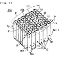
- Fig. 13 is a schematic perspective view of a battery module 200 formed by aligning and connecting seven tubular battery cells 1 in parallel to form a battery group 10, and aligning and connecting six battery groups 10 in series.
- the positive electrodes (+) of the tubular battery cells 1 in each battery group 10 are connected to each other by a positive electrode current collector plate 21, and the negative electrodes (-) are connected to each other by a negative electrode current collector plate 22.
- the battery groups 10 are connected to each other in series by a plurality of conductive strips 111.
- a positive electrode lead (a positive electrode terminal) 12 is connected to the positive electrode current collector plate 21 in the vicinity of a battery group 10a, and a negative electrode lead (a negative electrode terminal) 13 is connected to the negative electrode current collector plate 22 in the vicinity of a battery group 10f.
- the charge/discharge current tends to pass preferentially along the shortest distance (in the side A) between the positive electrode lead 12 and the negative electrode lead 13.
- the charge/discharge current is relatively difficult to flow.
- the temperature of a battery at a position close to the shortest distance between the positive electrode lead 12 and the negative electrode lead 13, for example, a tubular battery cell 1a is more likely to increase locally because the charge/discharge current flows preferentially therethrough.
- the temperature of a battery at a position away from the shortest distance between the positive electrode lead 12 and the negative electrode lead 13, for example, a tubular battery cell 1g is less likely to increase because the charge/discharge current is relatively difficult to pass therethrough. Because of the local increase in temperature, the tubular battery cell 1a deteriorates relatively earlier. On the other hand, in the tubular battery cell 1g, increase in temperature is comparatively less likely to occur.
- the electrical resistance of the deteriorated tubular battery cell becomes high, and the amount of Joule heat generated is further increased.
- the life of the battery module is influenced by a tubular battery cell whose life is short among the tubular battery cells. Therefore, when the life of a certain tubular battery cell expires, the life of the battery module expires even though the other tubular battery cells are in good condition.
- the present invention intends to provide a battery module having a long life by reducing variations in the progress of deterioration among the battery cells constituting the battery module.
- One aspect of the present invention is a battery module including a plurality of battery groups being connected in series and each comprising a plurality of battery cells connected in parallel, wherein: a positive electrode terminal and a negative electrode terminal are provided; the battery groups are connected to each other by a plurality of electrically conductive strips; and an electrical resistance value of the conductive strip arranged at a position near a virtual line drawn between the positive electrode terminal and the negative electrode terminal is high, and an electrical resistance value of the conductive strip arranged at a position other than the position near the virtual line is low, the electrical resistance value being measured in a direction of charge and discharge current flow.
- the battery module of the present invention has a longer life because deterioration proceeds evenly among the battery cells.
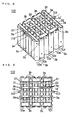
- Fig. 1 is a perspective schematic view showing the configuration of a battery module 100 according to First Embodiment of the present invention.
- Fig. 2 is a front side schematic view of the battery module 100
- Fig. 3 is a top view of the battery module 100
- Fig. 4 is a bottom view of the battery module 100.
- the battery module 100 is a battery module formed by connecting six battery groups 10 (10a, 10b, 10c, 10d, 10e and 10f) in series by a plurality of electrically conductive strips 2 (2a, 2b and 2c).
- Each of the battery groups 10 comprises linearly arranged seven tubular battery cells 1 (1a, 1b, 1c, 1d, 1e, 1f, and 1g) connected in parallel by a positive electrode current collector plate 21 and a negative electrode current collector plate 22.
- the tubular battery cell 1 is a cylindrical battery having a positive electrode (+) at one end thereof in the longitudinal direction and a negative electrode (-) at the other end thereof.
- the battery groups 10 are linearly aligned upright with the positive electrodes (+) of the seven tubular battery cells 1 being arranged in the same side and the negative electrodes (-) being arranged in the same side. Arranging the tubular battery cells 1 in such a manner is preferable because it can make the battery module more compact.
- the linearly arranged tubular battery cells 1 are securely positioned by being laminated or mounted on a frame.
- the positive electrodes (+) of the seven tubular battery cells 1 of the battery group 10 are connected to each other by the positive electrode current collector plate 21, and the negative electrodes (-) are connected to each other by the negative electrode current collector plate 22.
- the connection is made by, for example, welding.
- the positive electrode current collector plate 21 and the negative electrode current collector plate 22 are formed of an electrically conductive material.
- the conductive material may be, for example, a metal material such as stainless steel, titanium, aluminum, an aluminum alloy, nickel, copper, or a copper alloy.
- the tubular battery cell 1 may be either a secondary battery or a primary battery.
- the secondary battery include lithium ion secondary batteries, nickel-metal hydride secondary batteries, alkaline secondary storage batteries, lead storage batteries, and nickel-cadmium secondary batteries.
- the primary battery include manganese dry batteries, alkaline dry batteries, lithium primary batteries, and silver oxide batteries. Among these, secondary batteries, particularly lithium ion secondary batteries, are preferred.
- the battery groups 10a to 10f are arranged such that the positive electrodes (+) are alternated with the negative electrodes (-). This eases the series connection of the battery groups 10a to 10f by the conductive strips. Further, this can make the conductive strip smaller in size. As a result, the outer dimensions of the battery module 100 can be reduced. This can increase the variety of the devices for which the battery module 100 can be applied as a power source.
- the column of the battery group 10a is referred to as the first column
- the column of the battery group 10f is referred to as the sixth column.
- the line including the tubular battery cell 1a is referred to as the first line
- the line including the tubular battery cell 1g is referred to as the sixth line.
- the positive electrode current collector plates 21 are positioned at the top
- the negative electrode current collector plates 22 are positioned at the bottom.
- the positive electrode current collector plates 21 are positioned at the bottom
- the negative electrode current collector plates 22 are positioned at the top.
- the positive electrode lead (positive electrode terminal) 12 is connected to the positive electrode current collector plate 21 at a position near the tubular battery cell 1a in the first line of the first column of the battery group 10a, which is the end on the positive electrode side. This makes the current path from the positive electrode lead 12 to the tubular battery cell 1a shorter than any other current path from the positive electrode lead 12 to the tubular battery cell.
- the negative electrode lead (negative electrode terminal) 13 is connected to the negative electrode current collector plate 22 at a position near a tubular battery cell 1a' in the first line of the sixth column of the battery group 10f, which is the end on the negative electrode side. This makes the current path from the negative electrode lead 13 to the tubular battery cell 1a' shorter than any other current path from the negative electrode lead 13 to the tubular battery cell.
- the positive electrode lead 12 or the negative electrode lead 13 is formed of an electrically conductive material.
- the conductive material may be, for example, a metal material such as aluminum, an aluminum alloy, stainless steel, titanium, iron, nickel, copper, or a copper alloy.
- the adjacent battery groups 10 are connected to each other in series by connecting the positive electrode current collector plates 21 to the negative electrode current collector plates 22 by a plurality of conductive strips 2a, 2b and 2c.
- the conductive strip is a metal strip formed of an electrically conductive material.
- the conductive material may be, for example, stainless steel, iron, titanium, aluminum, an aluminum alloy, nickel, copper, a copper alloy, or an electrically conductive resin.
- the adjacent positive and negative electrode current collector plates 21 and 22 are connected to each other by three types of conductive strips 2a, 2b and 2c which are identical in the thickness and different in the width measured on a plane perpendicular to the direction of current flow.
- those of the conductive strip 2a are the smallest, and those of the conductive strip 2c are the largest.
- the electrical resistance between the positive electrode current collector plate 21 and the negative electrode current collector plate 22 becomes highest in the path on which the conductive strip 2a is arranged, and lowest in the path on which the conductive strip 2c is arranged.
- the dot-dash line shown in Figs. 1 , 3 and 4 is a virtual line drawn between the positive electrode lead 12 and the negative electrode lead 13.
- the shortest path of current in the battery module 100 is a current path along the virtual line.
- the conductive strips 2a arranged on a path close to the virtual line are the conductive strips 2a whose contact area with the positive electrode current collector plate 21 and the negative electrode current collector plate 22 is the smallest and whose cross-sectional area measured on a plane orthogonal to the direction of current flow is the smallest.
- the conductive strips 2c Arranged on a path farthest away from the virtual line are the conductive strips 2c whose contact area with the positive electrode current collector plate 21 and the negative electrode current collector plate 22 is the largest and whose cross-sectional area measured on a plane orthogonal to the direction of current flow is the largest. Arranged on a path therebetween are the conductive strips 2b whose contact area and cross-sectional area measured on a plane orthogonal to the direction of current flow are medium.
- the farther the path is away from the virtual line the larger the contact area and the cross-sectional area measured on a plane orthogonal to the direction of current flow of the current strips 2 are.
- By increasing the contact area and the cross-sectional area measured on a plane orthogonal to the direction of current flow of the conductive strips 2 as the conductive strips 2 are farther away from the virtual line thereby to reduce the electrical resistance value accordingly, more current is allowed to flow in a path away from the virtual line, along which current would otherwise be difficult to flow.
- current flows evenly through a plurality of the tubular battery cells 1 load is evenly applied to all the tubular battery cells 1, and variations in battery life among the tubular battery cells 1 are reduced. Therefore, the battery module 100 can have a longer life.
- the conductive strip 2 may be connected to the positive electrode current collector plate 21 or the negative electrode current collector plate 22 by any method without particular limitation. Examples of the method include welding, bonding using a conductive adhesive, and joining using a joint part such as a screw. Alternatively, the connection may be achieved by forming a recess at a predetermined position on the surface of the positive electrode current collector plate 21 or the negative electrode current collector plate 22, and fitting the conductive strip 2 into the recess.
- the battery module 1 is usually accommodated into a housing made of a resin material, a rubber material, a ceramics material, or a metal material, a package of laminate sheet, or the like.
- the battery group 10 is composed of seven tubular battery cells, the number of the tubular battery cells is not limited to seven and may be adjusted as appropriate according to the intended use thereof. Further, although six battery groups are connected in series in the battery module 100, the number of the battery groups is not limited to six and may be adjusted as appropriate according to the intended use thereof. Furthermore, although the battery cell 1 is a tubular battery cell of a cylindrical shape, the battery cell 1 may be of any shape without particular limitation and may be a prismatic battery or a flat battery.
- the battery groups 1 are arranged such that the positive electrode current collector plates 21 are alternated with the negative electrode current collector plates 22 in the battery module 100, this is not a limitation.
- the battery groups 1 may be arranged such that the positive electrode current collector plates 21 are arranged in the same side and the negative electrode current collector plates 22 are arranged in the same side.
- a battery module 110 which is another embodiment of the battery module according to the present invention, is described with reference to Figs. 5 and 6.
- Fig. 5 is a perspective schematic view showing the configuration of the battery module 110.
- Fig. 6 is a bottom schematic view of the battery module 110.
- the same component elements as those described with reference to Figs. 1 to 4 in First Embodiment are denoted by the same reference numerals.
- the battery module 110 is the same as the battery module 100, except that the connecting positions of the positive electrode lead and the negative electrode lead are changed, and the type of conductive strip is changed.
- a positive electrode lead 112 is connected to the positive electrode current collector plate 21 at a position near the tubular battery cell 1d in the fourth line positioned at the center of the first column of battery group 10a, which is the end on the positive electrode side. This makes the current path from the positive electrode lead 112 to the tubular battery cell 1d shorter than any other current path from the positive electrode lead 112 to the tubular battery cell.
- a negative electrode lead 113 is connected to the negative electrode current collector plate 22 at a position near a tubular battery cell 1d' in the fourth line of the sixth column of the battery group 10f, which is the end on the negative electrode side. This makes the current path from the negative electrode lead 113 to the tubular battery cell 1d' shorter than any other current path from the negative electrode lead 113 to the tubular battery cell.
- the adjacent battery groups 10 are connected to each other in series by connecting the positive electrode current collector plate 21 to the negative electrode current collector plate 22 by a plurality of conductive strips 3a and 3b.
- the adjacent positive and negative electrode current collector plates 21 and 22 are connected to each other by two types of conductive strips 3a and 3b which are identical in the thickness and different in the width measured on a plane orthogonal to the direction of current flow.
- the area when viewed from the top and the width measured on a plane orthogonal to the direction of current flow of the conductive strip 3a are smaller than those of the conductive strip 3b. As such, the electrical resistance of the path on which the conductive strip 3a is arranged becomes higher than that of the path on which the conductive strip 3b is arranged.
- the dot-dash line shown in Figs. 5 and 6 is a virtual line drawn between the positive electrode lead 112 and the negative electrode lead 113.
- the arrangement of the conductive strips 3a and 3b is symmetric about the virtual line.
- Arranged on a path closest to the virtual line are the conductive strips 3a whose contact area with the current collector plates is small and whose cross-sectional area measured on a plane orthogonal to the direction of current flow is small.
- Arranged on a path away from the virtual line are the conductive strips 3b whose contact area with the current collector plates is large and whose cross-sectional area measured on a plane orthogonal to the direction of current flow is large.
- the conductive strips 3b are arranged on a path away from the virtual line.
- the conducive strips 3b whose contact area with the current collector plates is large and whose cross-sectional area measured on a plane orthogonal to the direction of current flow is large, on a path away from the virtual line, more current is allowed to flow in a path away from the virtual line, along which current would otherwise be difficult to flow.
- current flows evenly through a plurality of the tubular battery cells 1, load is evenly applied to all the tubular battery cells 1, and variations in battery life among the tubular battery cells 1 are reduced. Therefore, the battery module 110 can have a longer life.
- a battery module 120 which is yet another embodiment of the battery module according to the present invention, is described with reference to Figs. 7 and 8.
- Fig. 7 is a perspective schematic view of the battery module 120
- Fig. 8 is a bottom schematic view of the battery module 120.
- the same component elements as those described with reference to Figs. 1 to 4 in First Embodiment are denoted by the same reference numerals.
- the battery module 120 is the same as the battery module 100, except that the connecting positions of the positive electrode lead and the negative electrode lead are changed, and the type of conductive strip is changed.
- a positive electrode lead 212 is connected to the positive electrode current collector plate 21 at a position near the tubular battery cell 1g in the seventh line positioned at the end of the first column of the battery group 10a, which is the end on the positive electrode side. This makes the current path from the positive electrode lead 212 to the tubular battery cell 1g shorter than any other current path from the positive electrode lead 212 to the tubular battery cell.
- a negative electrode lead 213 is connected to the negative electrode current collector plate 22 at a position near the tubular battery cell 1a' in the first line of the sixth column of the battery group 10f, which is the end on the negative electrode side. This makes the current path from the negative electrode lead 213 to the tubular battery cell 1a' shorter than any other current path from the negative electrode lead 213 to the tubular battery cell.
- the adjacent battery groups 10 are connected to each other in series by connecting the positive electrode current collector plate 21 to the negative electrode current collector plate 22 by a plurality of conductive strips 4a, 4b and 4c.
- the adjacent positive and negative electrode current collector plates 21 and 22 are connected to each other by three types of conductive strips 4a, 4b and 4c which are identical in the thickness and different in the width measured on a plane orthogonal to the direction of current flow.
- those of the conductive strip 4a are the smallest, and those of the conductive strip 4c are the largest.
- the electrical resistance of the path on which the conductive strip 4a is arranged becomes higher than that of the path on which the conductive strip 4b or 4c is arranged.
- the dot-dash line shown in Figs. 7 and 8 is a virtual line drawn between the positive electrode lead 212 and the negative electrode lead 213.
- the arrangement of the conductive strips 4a, 4b and 4c is symmetric about the virtual line.
- Arranged on a path closest to the virtual line are the conductive strips 4a whose contact area with the current collector plates is the smallest and whose cross-sectional area measured on a plane orthogonal to the direction of current flow is the smallest.
- Arranged on a path farthest away from the virtual line are the conductive strips 4c whose contact area with the current collector plates is the largest and whose cross-sectional area measured on a plane orthogonal to the direction of current flow is the largest.
- Arranged therebetween are the conductive strips 4b whose contact area and cross-sectional area measured on a plane orthogonal to the direction of current flow are medium.
- FIG. 9 is a perspective schematic view of the battery module 130
- Fig. 10 is a bottom schematic view of the battery module 130.
- the same component elements as those described with reference to Figs. 1 to 4 in First Embodiment are denoted by the same reference numerals.
- the battery module 130 is the same as the battery module 100, except that the type of conductive strip is changed.
- a positive electrode lead 312 is connected to the positive electrode current collector plate 21 at a position near the tubular battery cell 1a in the first line of the first column of the battery group 10a, which is the end on the positive electrode side. This makes the current path from the positive electrode lead 312 to the tubular battery cell 1a shorter than any other current path from the positive electrode lead 312 to the tubular battery cell.
- a negative electrode lead 313 is connected to the negative electrode current collector plate 22 at a position near the tubular battery cell 1a' in the first line of the sixth column of the battery group 10f, which is the end on the negative electrode side. This makes the current path from the negative electrode lead 313 to the tubular battery cell 1a' shorter than any other current path from the negative electrode lead 313 to the tubular battery cell.
- the adjacent battery groups are connected to each other in series by connecting the positive electrode current collector plate 21 to the negative electrode current collector plate 22 by a plurality of conductive strips 5a, 5b and 5c.
- the adjacent positive and negative electrode current collector plates 21 and 22 are connected to each other by three types of conductive strips 5a, 5b and 5c which are different from one another in the thickness only.
- the conductive strips 5a, 5b and 5c have the same shape when viewed from the top.
- the thickness of the conductive strip 5a is the smallest, and that of the conductive strip 5c is the largest. As such, the electrical resistance of the path on which the conductive strip 5a is arranged becomes higher than that of the path on which the conductive strip 5b or 5c is arranged.
- the dot-dash line shown in Figs. 9 and 10 is a virtual line drawn between the positive electrode lead 312 and the negative electrode lead 313.
- the shortest path of current in the battery module 130 is a path along the virtual line.
- the conductive strips 5a whose thickness is the smallest, that is, whose cross-sectional area measured on a plane orthogonal to the direction of current flow is the smallest.
- the conductive strips 5c whose thickness is the largest, that is, whose cross-sectional area measured on a plane orthogonal to the direction of current flow is the largest.
- Arranged on a path therebetween are the conductive strips 5b whose thickness is medium.
- FIG. 11 is a perspective schematic view of the battery module 140
- Fig. 12 is a bottom schematic view of the battery module 140.
- the same component elements as those described with reference to Figs. 1 to 4 in First Embodiment are denoted by the same reference numerals.
- the battery module 140 is the same as the battery module 100, except that the type of conductive strip is changed.
- a positive electrode lead 412 is connected to the positive electrode current collector plate 21 at a position near the tubular battery cell 1a in the first line of the first column of the battery group 10a, which is the end on the positive electrode side. This makes the current path from the positive electrode lead 412 to the tubular battery cell 1a shorter than any other current path from the positive electrode lead 412 to the tubular battery cell.
- a negative electrode lead 413 is connected to the negative electrode current collector plate 22 at a position near the tubular battery cell 1a' in the first line of the sixth column of the battery group 10f, which is the end on the negative electrode side. This makes the current path from the negative electrode lead 413 to the tubular battery cell 1a' shorter than any other current path from the negative electrode lead 413 to the tubular battery cell.
- the adjacent battery groups are connected to each other in series by connecting the positive electrode current collector plate 21 to the negative electrode current collector plate 22 by a plurality of conductive strips 6a, 6b and 6c.
- the adjacent positive and negative electrode current collector plates 21 and 22 are connected to each other by three types of conductive strips 6a, 6b and 6c which are made of electrically conductive materials different from one another in specific resistance only.
- the conductive strips 6a, 6b and 6c are identical in the shape and different from one another in the specific resistance value only.
- the specific resistance vale of the conductive strip 6a is the highest, and that of the conductive strip 6c is the lowest. As such, the electrical resistance of the path on which the conductive strip 6a is arranged becomes higher than that of the path on which the conductive strip 6b or 6c is arranged.
- the dot-dash line shown in Figs. 11 and 12 is a virtual line drawn between the positive electrode lead 412 and the negative electrode lead 413.
- the shortest path of current in the battery module 140 is a path along the virtual line.
- the conductive strips 6a whose specific resistance value is the highest.
- the conductive strips 6c whose specific resistance is the lowest.
- the conductive strips 6b whose specific resistance value is medium.
- the charge/discharge current flows evenly though a plurality of the tubular battery cells.
- variations in deterioration among the tubular battery cells are reduced, thus providing a longer life.
- the battery module of the present invention is applicable to transportation equipment such as electric vehicles, hybrid electric vehicles, fuel cell-powered vehicles, and plug-in HEVs, electric powered tools, vacuum cleaners, machining equipment such as robots, power storage equipment, and the like.
- the battery module of the present invention can be used as a power source for electric equipment and electronic equipment, and is particularly useful as a power source for portable electronic equipment.
- portable electronic equipment include personal computers, cellular phones, mobile devices, personal digital assistants, portable game machines, and video cameras.
Landscapes
- Chemical & Material Sciences (AREA)
- Chemical Kinetics & Catalysis (AREA)
- Electrochemistry (AREA)
- General Chemical & Material Sciences (AREA)
- Engineering & Computer Science (AREA)
- Manufacturing & Machinery (AREA)
- Battery Mounting, Suspending (AREA)
- Connection Of Batteries Or Terminals (AREA)
Abstract
Description
- The present invention relates to a battery module comprising a plurality of battery groups being connected in series and each comprising a plurality of battery cells connected in parallel. More specifically, the present invention relates to a battery module formed by connecting battery groups by an improved method.
- Batteries have started to be used as a power source for transportation equipment, machining equipment, power storage equipment and the like, in addition to be used as a driving power source for electric equipment and electronic equipment. The batteries used for transportation equipment, machining equipment, and power storage equipment are required to provide an instantaneous or continuous high output. A battery group formed by connecting a plurality of battery cells, or a battery module formed by further connecting these battery groups satisfies such a requirement.
- For example,
Patent Document 1 discloses a battery group comprising a plurality of battery cells connected in parallel, from which electric power is extracted through lead terminals. In this battery group, the connection resistance between a battery cell whose temperature tends to increase at a higher rate and the lead terminals is set larger than that between a battery cell whose temperature tends to increase at a lower rate and the lead terminals.Patent document 1 teaches that in the battery group comprising a plurality of battery cells connected in parallel, variations in capacity among the battery cells can be reduced by suppressing variations in temperature among the battery cells. - Patent Document 2 discloses a secondary battery system including: a secondary battery main body comprising battery modules connected in parallel, the battery modules each being formed by connecting a plurality of unit batteries; and a control unit for controlling the temperature of each battery module so that every battery module has the same internal electrical resistance.
- Both of the techniques disclosed in
Patent Documents 1 and 2 intend to suppress variations in temperature that might occur among the battery cells or among the battery modules. -
- Patent Document 1: Japanese Laid-Open Patent Publication No.
2004-31255 - Patent Document 2: Japanese Laid-Open Patent Publication No.
2008-109841 - In a battery module in which a plurality of battery cells are connected in parallel to form a battery group, and a plurality of the battery groups are further connected in series, the temperatures of the battery cells arranged in a specific region increase locally, which causes deterioration. The present inventors have understood this phenomenon as follows.
-
Fig. 13 is a schematic perspective view of abattery module 200 formed by aligning and connecting seventubular battery cells 1 in parallel to form abattery group 10, and aligning and connecting sixbattery groups 10 in series. The positive electrodes (+) of thetubular battery cells 1 in eachbattery group 10 are connected to each other by a positive electrodecurrent collector plate 21, and the negative electrodes (-) are connected to each other by a negative electrodecurrent collector plate 22. Thebattery groups 10 are connected to each other in series by a plurality ofconductive strips 111. A positive electrode lead (a positive electrode terminal) 12 is connected to the positive electrodecurrent collector plate 21 in the vicinity of abattery group 10a, and a negative electrode lead (a negative electrode terminal) 13 is connected to the negative electrodecurrent collector plate 22 in the vicinity of abattery group 10f. - In charging and discharging the
battery module 200, the charge/discharge current tends to pass preferentially along the shortest distance (in the side A) between thepositive electrode lead 12 and thenegative electrode lead 13. On the other hand, in the region away from the shortest distance between thepositive electrode lead 12 and thenegative electrode lead 13, for example, in the side B, there is a tendency that the charge/discharge current is relatively difficult to flow. - As such, among the
tubular battery cells 1, the temperature of a battery at a position close to the shortest distance between thepositive electrode lead 12 and thenegative electrode lead 13, for example, atubular battery cell 1a, is more likely to increase locally because the charge/discharge current flows preferentially therethrough. On the other hand, the temperature of a battery at a position away from the shortest distance between thepositive electrode lead 12 and thenegative electrode lead 13, for example, atubular battery cell 1g, is less likely to increase because the charge/discharge current is relatively difficult to pass therethrough. Because of the local increase in temperature, thetubular battery cell 1a deteriorates relatively earlier. On the other hand, in thetubular battery cell 1g, increase in temperature is comparatively less likely to occur. - If there occurs a difference in the degree of deterioration among the tubular battery cells, the electrical resistance of the deteriorated tubular battery cell becomes high, and the amount of Joule heat generated is further increased. As a result, the deterioration of the tubular battery cell whose deterioration has started earlier is accelerated. The life of the battery module is influenced by a tubular battery cell whose life is short among the tubular battery cells. Therefore, when the life of a certain tubular battery cell expires, the life of the battery module expires even though the other tubular battery cells are in good condition.
- The present invention intends to provide a battery module having a long life by reducing variations in the progress of deterioration among the battery cells constituting the battery module.
- One aspect of the present invention is a battery module including a plurality of battery groups being connected in series and each comprising a plurality of battery cells connected in parallel, wherein: a positive electrode terminal and a negative electrode terminal are provided; the battery groups are connected to each other by a plurality of electrically conductive strips; and an electrical resistance value of the conductive strip arranged at a position near a virtual line drawn between the positive electrode terminal and the negative electrode terminal is high, and an electrical resistance value of the conductive strip arranged at a position other than the position near the virtual line is low, the electrical resistance value being measured in a direction of charge and discharge current flow.
The foregoing and other objects, features, aspects, and advantages of the present invention will be more apparent from the following detailed description and the accompanying drawings. - The battery module of the present invention has a longer life because deterioration proceeds evenly among the battery cells.
-
- [Fig. 1]
- A perspective schematic view of a
battery module 100 of First Embodiment. - [Fig. 2]
- Aside schematic view of the
battery module 100. - [Fig. 3]
- A top schematic view of the
battery module 100. - [Fig. 4]
- A bottom schematic view of the
battery module 100. - [Fig. 5]
- A perspective schematic view of a
battery module 110 of Second Embodiment. - [Fig. 6]
- A bottom schematic view of the
battery module 110. - [Fig. 7]
- A perspective schematic view of a
battery module 120 of Third Embodiment. - [Fig. 8]
- A bottom schematic view of the
battery module 120. - [Fig. 9]
- A perspective schematic view of a
battery module 130 of Forth Embodiment. - [Fig. 10]
- A bottom schematic view of the
battery module 130. - [Fig. 11]
- A perspective schematic view of a
battery module 140 of Fifth Embodiment. - [Fig. 12]
- A bottom schematic view of the
battery module 140. - [Fig. 13]
- A perspective schematic view of a
battery module 200. -
Fig. 1 is a perspective schematic view showing the configuration of abattery module 100 according to First Embodiment of the present invention.Fig. 2 is a front side schematic view of thebattery module 100,Fig. 3 is a top view of thebattery module 100, andFig. 4 is a bottom view of thebattery module 100. - The
battery module 100 is a battery module formed by connecting six battery groups 10 (10a, 10b, 10c, 10d, 10e and 10f) in series by a plurality of electrically conductive strips 2 (2a, 2b and 2c). - Each of the
battery groups 10 comprises linearly arranged seven tubular battery cells 1 (1a, 1b, 1c, 1d, 1e, 1f, and 1g) connected in parallel by a positive electrodecurrent collector plate 21 and a negative electrodecurrent collector plate 22. - The
tubular battery cell 1 is a cylindrical battery having a positive electrode (+) at one end thereof in the longitudinal direction and a negative electrode (-) at the other end thereof. Thebattery groups 10 are linearly aligned upright with the positive electrodes (+) of the seventubular battery cells 1 being arranged in the same side and the negative electrodes (-) being arranged in the same side. Arranging thetubular battery cells 1 in such a manner is preferable because it can make the battery module more compact. Preferably, the linearly arrangedtubular battery cells 1 are securely positioned by being laminated or mounted on a frame. - The positive electrodes (+) of the seven
tubular battery cells 1 of thebattery group 10 are connected to each other by the positive electrodecurrent collector plate 21, and the negative electrodes (-) are connected to each other by the negative electrodecurrent collector plate 22. The connection is made by, for example, welding. The positive electrodecurrent collector plate 21 and the negative electrodecurrent collector plate 22 are formed of an electrically conductive material. The conductive material may be, for example, a metal material such as stainless steel, titanium, aluminum, an aluminum alloy, nickel, copper, or a copper alloy. - The
tubular battery cell 1 may be either a secondary battery or a primary battery. Examples of the secondary battery include lithium ion secondary batteries, nickel-metal hydride secondary batteries, alkaline secondary storage batteries, lead storage batteries, and nickel-cadmium secondary batteries. Examples of the primary battery include manganese dry batteries, alkaline dry batteries, lithium primary batteries, and silver oxide batteries. Among these, secondary batteries, particularly lithium ion secondary batteries, are preferred. - As shown in
Fig. 2 , thebattery groups 10a to 10f are arranged such that the positive electrodes (+) are alternated with the negative electrodes (-). This eases the series connection of thebattery groups 10a to 10f by the conductive strips. Further, this can make the conductive strip smaller in size. As a result, the outer dimensions of thebattery module 100 can be reduced. This can increase the variety of the devices for which thebattery module 100 can be applied as a power source. - In each figure, the column of the
battery group 10a is referred to as the first column, and the column of thebattery group 10f is referred to as the sixth column. The line including thetubular battery cell 1a is referred to as the first line, and the line including thetubular battery cell 1g is referred to as the sixth line. As shown inFig. 1 and 2 , in thebattery groups current collector plates 21 are positioned at the top, and the negative electrodecurrent collector plates 22 are positioned at the bottom. In thebattery groups current collector plates 21 are positioned at the bottom, and the negative electrodecurrent collector plates 22 are positioned at the top. - The positive electrode lead (positive electrode terminal) 12 is connected to the positive electrode
current collector plate 21 at a position near thetubular battery cell 1a in the first line of the first column of thebattery group 10a, which is the end on the positive electrode side. This makes the current path from thepositive electrode lead 12 to thetubular battery cell 1a shorter than any other current path from thepositive electrode lead 12 to the tubular battery cell. The negative electrode lead (negative electrode terminal) 13 is connected to the negative electrodecurrent collector plate 22 at a position near atubular battery cell 1a' in the first line of the sixth column of thebattery group 10f, which is the end on the negative electrode side. This makes the current path from thenegative electrode lead 13 to thetubular battery cell 1a' shorter than any other current path from thenegative electrode lead 13 to the tubular battery cell. - The
positive electrode lead 12 or thenegative electrode lead 13 is formed of an electrically conductive material. The conductive material may be, for example, a metal material such as aluminum, an aluminum alloy, stainless steel, titanium, iron, nickel, copper, or a copper alloy. - As shown in
Figs. 1 to 4 , theadjacent battery groups 10 are connected to each other in series by connecting the positive electrodecurrent collector plates 21 to the negative electrodecurrent collector plates 22 by a plurality ofconductive strips - In the
battery module 100, the adjacent positive and negative electrodecurrent collector plates conductive strips conductive strip 2a are the smallest, and those of theconductive strip 2c are the largest. As such, the electrical resistance between the positive electrodecurrent collector plate 21 and the negative electrodecurrent collector plate 22 becomes highest in the path on which theconductive strip 2a is arranged, and lowest in the path on which theconductive strip 2c is arranged. - The dot-dash line shown in
Figs. 1 ,3 and 4 is a virtual line drawn between thepositive electrode lead 12 and thenegative electrode lead 13. The shortest path of current in thebattery module 100 is a current path along the virtual line. In thebattery module 100, arranged on a path close to the virtual line are theconductive strips 2a whose contact area with the positive electrodecurrent collector plate 21 and the negative electrodecurrent collector plate 22 is the smallest and whose cross-sectional area measured on a plane orthogonal to the direction of current flow is the smallest. Arranged on a path farthest away from the virtual line are theconductive strips 2c whose contact area with the positive electrodecurrent collector plate 21 and the negative electrodecurrent collector plate 22 is the largest and whose cross-sectional area measured on a plane orthogonal to the direction of current flow is the largest. Arranged on a path therebetween are theconductive strips 2b whose contact area and cross-sectional area measured on a plane orthogonal to the direction of current flow are medium. - Current to flow from a positive electrode lead to a negative electrode lead is more likely to flow in a shorter path therebetween. Specifically, current has a tendency to flow more in a path close to the virtual line drawn between the positive electrode lead and the negative electrode lead. In the
battery module 100, theconductive strips 2a whose contact area with the positive electrodecurrent collector plate 21 and the negative electrodecurrent collector plate 22 and whose cross-sectional area measured on a plane orthogonal to the direction of current flow are the smallest are arranged on a path close to the virtual line, so that the electrical resistance of the path close to the virtual line becomes higher than that of any other path. This prevents too much current from flowing in the path close to the virtual line. In addition, in thebattery module 100, the farther the path is away from the virtual line, the larger the contact area and the cross-sectional area measured on a plane orthogonal to the direction of current flow of the current strips 2 are. By increasing the contact area and the cross-sectional area measured on a plane orthogonal to the direction of current flow of the conductive strips 2 as the conductive strips 2 are farther away from the virtual line, thereby to reduce the electrical resistance value accordingly, more current is allowed to flow in a path away from the virtual line, along which current would otherwise be difficult to flow. As a result, current flows evenly through a plurality of thetubular battery cells 1, load is evenly applied to all thetubular battery cells 1, and variations in battery life among thetubular battery cells 1 are reduced. Therefore, thebattery module 100 can have a longer life. - The conductive strip 2 may be connected to the positive electrode
current collector plate 21 or the negative electrodecurrent collector plate 22 by any method without particular limitation. Examples of the method include welding, bonding using a conductive adhesive, and joining using a joint part such as a screw. Alternatively, the connection may be achieved by forming a recess at a predetermined position on the surface of the positive electrodecurrent collector plate 21 or the negative electrodecurrent collector plate 22, and fitting the conductive strip 2 into the recess. - The
battery module 1 is usually accommodated into a housing made of a resin material, a rubber material, a ceramics material, or a metal material, a package of laminate sheet, or the like. - Although the
battery group 10 is composed of seven tubular battery cells, the number of the tubular battery cells is not limited to seven and may be adjusted as appropriate according to the intended use thereof. Further, although six battery groups are connected in series in thebattery module 100, the number of the battery groups is not limited to six and may be adjusted as appropriate according to the intended use thereof. Furthermore, although thebattery cell 1 is a tubular battery cell of a cylindrical shape, thebattery cell 1 may be of any shape without particular limitation and may be a prismatic battery or a flat battery. - Although the
battery groups 1 are arranged such that the positive electrodecurrent collector plates 21 are alternated with the negative electrodecurrent collector plates 22 in thebattery module 100, this is not a limitation. For example, thebattery groups 1 may be arranged such that the positive electrodecurrent collector plates 21 are arranged in the same side and the negative electrodecurrent collector plates 22 are arranged in the same side. - A
battery module 110, which is another embodiment of the battery module according to the present invention, is described with reference toFigs. 5 and 6. Fig. 5 is a perspective schematic view showing the configuration of thebattery module 110.Fig. 6 is a bottom schematic view of thebattery module 110. Here, the same component elements as those described with reference toFigs. 1 to 4 in First Embodiment are denoted by the same reference numerals. - The
battery module 110 is the same as thebattery module 100, except that the connecting positions of the positive electrode lead and the negative electrode lead are changed, and the type of conductive strip is changed. - In the
battery module 110, apositive electrode lead 112 is connected to the positive electrodecurrent collector plate 21 at a position near thetubular battery cell 1d in the fourth line positioned at the center of the first column ofbattery group 10a, which is the end on the positive electrode side. This makes the current path from thepositive electrode lead 112 to thetubular battery cell 1d shorter than any other current path from thepositive electrode lead 112 to the tubular battery cell. Anegative electrode lead 113 is connected to the negative electrodecurrent collector plate 22 at a position near atubular battery cell 1d' in the fourth line of the sixth column of thebattery group 10f, which is the end on the negative electrode side. This makes the current path from thenegative electrode lead 113 to thetubular battery cell 1d' shorter than any other current path from thenegative electrode lead 113 to the tubular battery cell. - As shown in
Figs. 5 and 6 , theadjacent battery groups 10 are connected to each other in series by connecting the positive electrodecurrent collector plate 21 to the negative electrodecurrent collector plate 22 by a plurality ofconductive strips - In the
battery module 110, the adjacent positive and negative electrodecurrent collector plates conductive strips conductive strip 3a are smaller than those of theconductive strip 3b. As such, the electrical resistance of the path on which theconductive strip 3a is arranged becomes higher than that of the path on which theconductive strip 3b is arranged. - The dot-dash line shown in
Figs. 5 and 6 is a virtual line drawn between thepositive electrode lead 112 and thenegative electrode lead 113. In thebattery module 110, the arrangement of theconductive strips conductive strips 3a whose contact area with the current collector plates is small and whose cross-sectional area measured on a plane orthogonal to the direction of current flow is small. Arranged on a path away from the virtual line are theconductive strips 3b whose contact area with the current collector plates is large and whose cross-sectional area measured on a plane orthogonal to the direction of current flow is large. - Current has a tendency to flow more in a path close to the virtual line shown in
Figs. 5 and 6 . Accordingly, by arranging theconducive strips 3a on a path close to the virtual line, the electrical resistance of the path close to the virtual line becomes higher than that of any other path, preventing too much current from flowing therein. In thebattery module 110, theconductive strips 3b are arranged on a path away from the virtual line. By arranging theconducive strips 3b whose contact area with the current collector plates is large and whose cross-sectional area measured on a plane orthogonal to the direction of current flow is large, on a path away from the virtual line, more current is allowed to flow in a path away from the virtual line, along which current would otherwise be difficult to flow. As a result, current flows evenly through a plurality of thetubular battery cells 1, load is evenly applied to all thetubular battery cells 1, and variations in battery life among thetubular battery cells 1 are reduced. Therefore, thebattery module 110 can have a longer life. - A
battery module 120, which is yet another embodiment of the battery module according to the present invention, is described with reference toFigs. 7 and 8. Fig. 7 is a perspective schematic view of thebattery module 120, andFig. 8 is a bottom schematic view of thebattery module 120. Here, the same component elements as those described with reference toFigs. 1 to 4 in First Embodiment are denoted by the same reference numerals. - The
battery module 120 is the same as thebattery module 100, except that the connecting positions of the positive electrode lead and the negative electrode lead are changed, and the type of conductive strip is changed. - In the
battery module 120, apositive electrode lead 212 is connected to the positive electrodecurrent collector plate 21 at a position near thetubular battery cell 1g in the seventh line positioned at the end of the first column of thebattery group 10a, which is the end on the positive electrode side. This makes the current path from thepositive electrode lead 212 to thetubular battery cell 1g shorter than any other current path from thepositive electrode lead 212 to the tubular battery cell. Anegative electrode lead 213 is connected to the negative electrodecurrent collector plate 22 at a position near thetubular battery cell 1a' in the first line of the sixth column of thebattery group 10f, which is the end on the negative electrode side. This makes the current path from thenegative electrode lead 213 to thetubular battery cell 1a' shorter than any other current path from thenegative electrode lead 213 to the tubular battery cell. - As shown in
Figs. 7 and 8 , theadjacent battery groups 10 are connected to each other in series by connecting the positive electrodecurrent collector plate 21 to the negative electrodecurrent collector plate 22 by a plurality ofconductive strips - In the
battery module 120, the adjacent positive and negative electrodecurrent collector plates conductive strips conductive strips conductive strip 4a are the smallest, and those of theconductive strip 4c are the largest. As such, the electrical resistance of the path on which theconductive strip 4a is arranged becomes higher than that of the path on which theconductive strip - The dot-dash line shown in
Figs. 7 and 8 is a virtual line drawn between thepositive electrode lead 212 and thenegative electrode lead 213. In thebattery module 120, the arrangement of theconductive strips conductive strips 4a whose contact area with the current collector plates is the smallest and whose cross-sectional area measured on a plane orthogonal to the direction of current flow is the smallest. Arranged on a path farthest away from the virtual line are theconductive strips 4c whose contact area with the current collector plates is the largest and whose cross-sectional area measured on a plane orthogonal to the direction of current flow is the largest. Arranged therebetween are theconductive strips 4b whose contact area and cross-sectional area measured on a plane orthogonal to the direction of current flow are medium. - Current has a tendency to flow more in a path close to the virtual line shown in
Figs. 7 and 8 . Accordingly, by arranging theconducive strips 4a on a path close to the virtual line among the paths provided symmetrically about the virtual line, the resistance of the path close to the virtual line becomes higher than that of any other path, and this prevents too much current from flowing therein. In thebattery module 120, theconductive strips 4c are arranged on two paths away from the virtual line.
By arranging theconducive strips 4c whose contact area with the current collector plates is large and whose cross-sectional area measured on a plane orthogonal to the direction of current flow is large, on a path away from the virtual line, more current is allowed to flow in the path away from the virtual line, along which current would otherwise be difficult to flow. As a result, current flows evenly through a plurality of thetubular battery cells 1, and load is evenly applied to all thetubular battery cells 1, and variations in battery life among thetubular battery cells 1 are reduced. Therefore, thebattery module 120 can have a longer life. - A
battery module 130, which is still another embodiment of the battery module according to the present invention, is described with reference toFigs. 9 and 10. Fig. 9 is a perspective schematic view of thebattery module 130, andFig. 10 is a bottom schematic view of thebattery module 130. Here, the same component elements as those described with reference toFigs. 1 to 4 in First Embodiment are denoted by the same reference numerals. - The
battery module 130 is the same as thebattery module 100, except that the type of conductive strip is changed. - In the
battery module 130, apositive electrode lead 312 is connected to the positive electrodecurrent collector plate 21 at a position near thetubular battery cell 1a in the first line of the first column of thebattery group 10a, which is the end on the positive electrode side. This makes the current path from thepositive electrode lead 312 to thetubular battery cell 1a shorter than any other current path from thepositive electrode lead 312 to the tubular battery cell. Anegative electrode lead 313 is connected to the negative electrodecurrent collector plate 22 at a position near thetubular battery cell 1a' in the first line of the sixth column of thebattery group 10f, which is the end on the negative electrode side. This makes the current path from thenegative electrode lead 313 to thetubular battery cell 1a' shorter than any other current path from thenegative electrode lead 313 to the tubular battery cell. - As shown in
Figs. 9 and 10 , the adjacent battery groups are connected to each other in series by connecting the positive electrodecurrent collector plate 21 to the negative electrodecurrent collector plate 22 by a plurality ofconductive strips - In the
battery module 130, the adjacent positive and negative electrodecurrent collector plates conductive strips conductive strips conductive strip 5a is the smallest, and that of theconductive strip 5c is the largest. As such, the electrical resistance of the path on which theconductive strip 5a is arranged becomes higher than that of the path on which theconductive strip - The dot-dash line shown in
Figs. 9 and 10 is a virtual line drawn between thepositive electrode lead 312 and thenegative electrode lead 313. The shortest path of current in thebattery module 130 is a path along the virtual line. In thebattery module 130, arranged on a path close to the virtual line are theconductive strips 5a whose thickness is the smallest, that is, whose cross-sectional area measured on a plane orthogonal to the direction of current flow is the smallest. Arranged on a path farthest away from the virtual line are theconductive strips 5c whose thickness is the largest, that is, whose cross-sectional area measured on a plane orthogonal to the direction of current flow is the largest. Arranged on a path therebetween are theconductive strips 5b whose thickness is medium. - Current to flow from the positive electrode lead to the negative electrode lead has a tendency to flow more in the shortest path. Accordingly, by arranging on a path close to the virtual line the
conducive strips 5a whose thickness is the smallest, that is, whose cross-sectional area measured on a plane orthogonal to the direction of current flow is the smallest, the electrical resistance of the shortest path becomes higher than that of any other path, preventing too much current from flowing therein. In thebattery module 130, the farther the conductive strips are away from the virtual line, the larger the thickness of the conductive strips is. By increasing the thickness of the conductive strips as the conductive strips are farther away from the virtual line, more current is allowed to flow in a path away from the virtual line, along which current would otherwise be difficult to flow. As a result, current flows evenly through a plurality of thetubular battery cells 1, load is evenly applied to all thetubular battery cells 1, and variations in battery life among thetubular battery cells 1 are reduced. Therefore, thebattery module 130 can have a longer life. - A
battery module 140, which is yet another embodiment of the battery module according to the present invention, is described with reference toFigs. 11 and 12. Fig. 11 is a perspective schematic view of thebattery module 140, andFig. 12 is a bottom schematic view of thebattery module 140. Here, the same component elements as those described with reference toFigs. 1 to 4 in First Embodiment are denoted by the same reference numerals. - The
battery module 140 is the same as thebattery module 100, except that the type of conductive strip is changed. - In the
battery module 140, apositive electrode lead 412 is connected to the positive electrodecurrent collector plate 21 at a position near thetubular battery cell 1a in the first line of the first column of thebattery group 10a, which is the end on the positive electrode side. This makes the current path from thepositive electrode lead 412 to thetubular battery cell 1a shorter than any other current path from thepositive electrode lead 412 to the tubular battery cell. Anegative electrode lead 413 is connected to the negative electrodecurrent collector plate 22 at a position near thetubular battery cell 1a' in the first line of the sixth column of thebattery group 10f, which is the end on the negative electrode side. This makes the current path from thenegative electrode lead 413 to thetubular battery cell 1a' shorter than any other current path from thenegative electrode lead 413 to the tubular battery cell. - As shown in
Figs. 11 and 12 , the adjacent battery groups are connected to each other in series by connecting the positive electrodecurrent collector plate 21 to the negative electrodecurrent collector plate 22 by a plurality ofconductive strips - In the
battery module 140, the adjacent positive and negative electrodecurrent collector plates conductive strips conductive strips conductive strip 6a is the highest, and that of theconductive strip 6c is the lowest. As such, the electrical resistance of the path on which theconductive strip 6a is arranged becomes higher than that of the path on which theconductive strip - The dot-dash line shown in
Figs. 11 and 12 is a virtual line drawn between thepositive electrode lead 412 and thenegative electrode lead 413. The shortest path of current in thebattery module 140 is a path along the virtual line. In thebattery module 140, arranged on a path close to the virtual line are theconductive strips 6a whose specific resistance value is the highest. Arranged on a path farthest away from the virtual line are theconductive strips 6c whose specific resistance is the lowest. Arranged on a path therebetween are theconductive strips 6b whose specific resistance value is medium. - Current to flow from the positive electrode lead to the negative electrode lead is more likely to flow in the shortest path. Accordingly, by arranging on a path close to the virtual line the
conductive strips 6a whose specific resistance value is the highest, the electrical resistance of the shortest path becomes higher than that of any other path, preventing too much current from flowing therein. In thebattery module 140, the farther the conductive strips are away from the virtual line, the higher the specific resistance value of the conductive strips is. By decreasing the specific resistance value of the conductive strips as the conductive strips are farther away from the virtual line, more current is allowed to flow in a path away from the virtual line, along which current would otherwise be difficult to flow. As a result, current flows evenly through a plurality of thetubular battery cells 1, load is evenly applied to all thetubular battery cells 1, and variations in battery life among thetubular battery cells 1 are reduced. Therefore, thebattery module 140 can have a longer life. - In the battery modules described in the above embodiments, the charge/discharge current flows evenly though a plurality of the tubular battery cells. As a result, variations in deterioration among the tubular battery cells are reduced, thus providing a longer life.
- The battery module of the present invention is applicable to transportation equipment such as electric vehicles, hybrid electric vehicles, fuel cell-powered vehicles, and plug-in HEVs, electric powered tools, vacuum cleaners, machining equipment such as robots, power storage equipment, and the like. The battery module of the present invention can be used as a power source for electric equipment and electronic equipment, and is particularly useful as a power source for portable electronic equipment. Examples of portable electronic equipment include personal computers, cellular phones, mobile devices, personal digital assistants, portable game machines, and video cameras.
-
- 1 (1a, 1b, 1c, 1d, 1e, 1f, 1g) Tubular battery cell
- 2 (2a, 2b, 2c) Conductive strip
- 3 (3a, 3b) Conductive strip
- 4 (4a, 4b, 4c) Conductive strip
- 5 (5a, 5b, 5c) Conductive strip
- 6 (6a, 6b, 6c) Conductive strip
- 111 Conductivestrip
- 10 (10a, 10b, 10c, 10d, 10e, 10f) Battery group
- 12, 112, 212, 312, 412 Positive electrode lead
- 13, 113, 213, 313, 413 Negative electrode lead
- 21 Positive electrode current collector plate
- 22 Negative electrode current collector plate
- 100, 110, 120, 130, 140, 200 Battery module
Claims (8)
- A battery module comprising;
a plurality of battery groups being connected in series and each comprising a plurality of battery cells connected in parallel, wherein:a positive electrode terminal and a negative electrode terminal are provided,the battery groups are connected to each other by a plurality of electrically conductive strips, andan electrical resistance value of the conductive strip arranged at a position near a virtual line drawn between the positive electrode terminal and the negative electrode terminal is high, and an electrical resistance value of the conductive strip arranged at a position other than the position near the virtual line is low, the electrical resistance value being measured in a direction of charge and discharge current flow. - The battery module in accordance with claim 1, wherein the farther the conductive strip is away from the virtual line, the lower the electrical resistance value of the conductive strip measured in the direction of charge and discharge current flow is.
- The battery module in accordance with claim 1, wherein:the battery cells each comprise a tubular battery cell;positive electrodes of the tubular battery cells of each of the battery groups are connected to each other by a positive electrode current collector plate, and negative electrodes of the tubular battery cells of each of the battery groups are connected to each other by a negative electrode current collector plate; andthe positive electrode terminal is connected to one of the positive electrode current collector plates, and the negative electrode terminal is connected to one of the negative electrode current collector plates.
- The battery module in accordance with claim 3, wherein:in each of the battery groups, the tubular battery cells are linearly arranged upright and connected in parallel to each other.
- The battery module in accordance with claim 1, wherein the farther the conductive strip is away from the virtual line, the larger a cross sectional area of the conductive strip measured on a cross section perpendicular to the direction of charge and discharge current flow is.
- The battery module in accordance with claim 5, wherein
the conductive strips have the same thickness, and
the farther the conductive strip is away from the virtual line, the larger an area of the conductive strip when viewed from the top is. - The battery module in accordance with claim 5, wherein
the conductive strips have the same area when viewed from the top, and
the farther the conductive strip is away from the virtual line, the larger a thickness of the conductive strip is. - The battery module in accordance with claim 5, wherein
the conductive strips have the same shape, and
the farther the conductive strip is away from the virtual line, the lower a specific resistance value of the conductive strip is.
Applications Claiming Priority (2)
| Application Number | Priority Date | Filing Date | Title |
|---|---|---|---|
| JP2010016911 | 2010-01-28 | ||
| PCT/JP2010/007090 WO2011092782A1 (en) | 2010-01-28 | 2010-12-06 | Cell module |
Publications (2)
| Publication Number | Publication Date |
|---|---|
| EP2381512A1 true EP2381512A1 (en) | 2011-10-26 |
| EP2381512A4 EP2381512A4 (en) | 2016-11-16 |
Family
ID=44318795
Family Applications (1)
| Application Number | Title | Priority Date | Filing Date |
|---|---|---|---|
| EP10830931.1A Withdrawn EP2381512A4 (en) | 2010-01-28 | 2010-12-06 | Cell module |
Country Status (6)
| Country | Link |
|---|---|
| US (1) | US8487631B2 (en) |
| EP (1) | EP2381512A4 (en) |
| JP (1) | JP5210434B2 (en) |
| KR (1) | KR101196074B1 (en) |
| CN (1) | CN102257655B (en) |
| WO (1) | WO2011092782A1 (en) |
Cited By (3)
| Publication number | Priority date | Publication date | Assignee | Title |
|---|---|---|---|---|
| CN103904263A (en) * | 2014-04-02 | 2014-07-02 | 哈尔滨工程大学 | Micro-miniature underwater robot battery compartment |
| KR101482614B1 (en) * | 2013-09-10 | 2015-01-15 | 주식회사 아이티엠반도체 | Separator of battery pack and module of battery pack |
| EP3800691A1 (en) * | 2019-10-03 | 2021-04-07 | Siemens Aktiengesellschaft | Current collector, battery module with a current collector and usage thereof |
Families Citing this family (31)
| Publication number | Priority date | Publication date | Assignee | Title |
|---|---|---|---|---|
| US8736273B2 (en) * | 2010-04-15 | 2014-05-27 | Lg Chem, Ltd. | Testing system and method for testing a battery cell |
| WO2013021604A1 (en) * | 2011-08-05 | 2013-02-14 | パナソニック株式会社 | Electronic device |
| KR101891481B1 (en) * | 2011-09-16 | 2018-08-24 | 에스케이이노베이션 주식회사 | Connecting Structure of Secondary Battery Cell |
| US8716981B2 (en) | 2011-11-11 | 2014-05-06 | Lg Chem, Ltd. | System and method for cooling and cycling a battery pack |
| US8816692B2 (en) | 2011-12-01 | 2014-08-26 | Lg Chem, Ltd. | Test system for a battery module |
| CN102420303A (en) * | 2011-12-02 | 2012-04-18 | 苏州冠硕新能源有限公司 | Battery pack |
| CN102420304A (en) * | 2011-12-02 | 2012-04-18 | 苏州冠硕新能源有限公司 | Battery conductive piece and battery assembly using same |
| JP5704098B2 (en) * | 2012-03-19 | 2015-04-22 | トヨタ自動車株式会社 | Power storage device |
| US9063179B2 (en) | 2012-09-26 | 2015-06-23 | Lg Chem, Ltd. | System and method for determining an isolation resistance of a battery pack disposed on a vehicle chassis |
| CN102969752A (en) * | 2012-10-31 | 2013-03-13 | 西安韦德沃德航空科技有限公司 | Modular chargeable power supply system |
| JP5907050B2 (en) * | 2012-12-10 | 2016-04-20 | 株式会社デンソー | Battery system |
| US9164151B2 (en) | 2013-08-07 | 2015-10-20 | Lg Chem, Ltd. | System and method for determining isolation resistances of a battery pack |
| KR101637942B1 (en) * | 2013-08-29 | 2016-07-08 | 주식회사 엘지화학 | Gripper assembly for battery formation |
| KR101749509B1 (en) * | 2013-09-13 | 2017-06-21 | 삼성에스디아이 주식회사 | Battery pack having welding portion |
| CN103887468A (en) * | 2014-04-04 | 2014-06-25 | 河北安耐哲新能源技术有限公司 | Cylindrical lithium ion cell grouped battery |
| CN103887567B (en) * | 2014-04-21 | 2016-06-22 | 四川宝生实业发展有限公司 | Pure electric bus Ni-MH battery group |
| CN104701564A (en) * | 2014-08-27 | 2015-06-10 | 北京精密机电控制设备研究所 | Zinc-silver oxide battery pack |
| US10115943B2 (en) * | 2015-11-02 | 2018-10-30 | Korea Institute Of Energy Research | Battery packing module and battery pack |
| CN105280969B (en) * | 2015-11-25 | 2018-02-06 | 合肥国轩高科动力能源有限公司 | A lithium iron phosphate battery matching method for reducing the discharge voltage difference between series battery packs |
| US10319494B2 (en) * | 2016-02-05 | 2019-06-11 | Ematrix Energy Systems, Inc. | Multi-functional busbar with interstitial passages |
| US10784545B2 (en) * | 2016-03-25 | 2020-09-22 | Xing Power Inc. | Submerged cell modular battery system |
| JP6635309B2 (en) * | 2016-11-17 | 2020-01-22 | トヨタ自動車株式会社 | Battery pack |
| JP7114488B2 (en) * | 2017-01-30 | 2022-08-08 | 三洋電機株式会社 | power supply |
| JP7044614B2 (en) * | 2018-04-09 | 2022-03-30 | 矢崎総業株式会社 | Busbar module, battery module, battery pack and battery cell connection method |
| US10573859B2 (en) | 2018-07-03 | 2020-02-25 | Daniel Francis Roddy | Portable modular energy storage |
| US10720614B2 (en) | 2018-09-28 | 2020-07-21 | Daniel Francis Roddy | Portable modular energy storage |
| US10446809B1 (en) | 2018-09-28 | 2019-10-15 | Daniel Francis Roddy | Portable modular energy storage |
| MX2021011134A (en) | 2019-03-14 | 2021-12-10 | Generac Power Systems Inc | THERMAL MANAGEMENT OF THE BATTERY MODULE. |
| CN111162219A (en) * | 2020-01-17 | 2020-05-15 | 北斗航天汽车(北京)有限公司 | Battery PACK of electricity core monomer cluster and parallel combination |
| CN111755640A (en) * | 2020-05-21 | 2020-10-09 | 深圳市炜烨丰电子科技有限公司 | Battery pack and method for manufacturing battery pack |
| KR102885098B1 (en) * | 2020-12-28 | 2025-11-11 | 주식회사 엘지에너지솔루션 | A battery module with multiple parallel battery cells |
Family Cites Families (11)
| Publication number | Priority date | Publication date | Assignee | Title |
|---|---|---|---|---|
| JPH01179357A (en) | 1988-01-04 | 1989-07-17 | Toshiba Corp | Manufacture of semiconductor device |
| JPH064534Y2 (en) * | 1988-06-09 | 1994-02-02 | 三洋電機株式会社 | Battery device |
| JP3635995B2 (en) * | 1999-08-26 | 2005-04-06 | 新神戸電機株式会社 | Assembled battery |
| CA2463135C (en) * | 2001-10-11 | 2014-10-07 | Denovo Research, Llc | Dynamic battery array controllable to provide individual electrical power busses for different electrical loads |
| JP2004031255A (en) | 2002-06-28 | 2004-01-29 | Nissan Motor Co Ltd | Battery pack |
| JP2008109841A (en) | 2006-09-25 | 2008-05-08 | Tokyo Electric Power Co Inc:The | Secondary battery system |
| KR100908568B1 (en) * | 2006-10-23 | 2009-07-22 | 주식회사 엘지화학 | Uniform distribution type connection member and medium-large battery pack including the same |
| JP2008153150A (en) * | 2006-12-20 | 2008-07-03 | Daiwa House Ind Co Ltd | Parallel battery pack |
| JP5200420B2 (en) * | 2007-05-16 | 2013-06-05 | ソニー株式会社 | Battery pack |
| JP5205805B2 (en) * | 2007-05-16 | 2013-06-05 | ソニー株式会社 | Battery pack |
| WO2011074097A1 (en) * | 2009-12-17 | 2011-06-23 | トヨタ自動車株式会社 | Sulfide-containing solid electrolyte cell, battery pack comprising the cell, vehicle system comprising the battery pack, and method for sensing hydrogen sulfide |
-
2010
- 2010-12-06 EP EP10830931.1A patent/EP2381512A4/en not_active Withdrawn
- 2010-12-06 CN CN201080003628.7A patent/CN102257655B/en active Active
- 2010-12-06 WO PCT/JP2010/007090 patent/WO2011092782A1/en not_active Ceased
- 2010-12-06 US US13/139,161 patent/US8487631B2/en active Active
- 2010-12-06 KR KR1020117012825A patent/KR101196074B1/en active Active
- 2010-12-06 JP JP2011511552A patent/JP5210434B2/en active Active
Non-Patent Citations (1)
| Title |
|---|
| See references of WO2011092782A1 * |
Cited By (3)
| Publication number | Priority date | Publication date | Assignee | Title |
|---|---|---|---|---|
| KR101482614B1 (en) * | 2013-09-10 | 2015-01-15 | 주식회사 아이티엠반도체 | Separator of battery pack and module of battery pack |
| CN103904263A (en) * | 2014-04-02 | 2014-07-02 | 哈尔滨工程大学 | Micro-miniature underwater robot battery compartment |
| EP3800691A1 (en) * | 2019-10-03 | 2021-04-07 | Siemens Aktiengesellschaft | Current collector, battery module with a current collector and usage thereof |
Also Published As
| Publication number | Publication date |
|---|---|
| KR20110103389A (en) | 2011-09-20 |
| JPWO2011092782A1 (en) | 2013-05-30 |
| JP5210434B2 (en) | 2013-06-12 |
| EP2381512A4 (en) | 2016-11-16 |
| KR101196074B1 (en) | 2012-11-01 |
| CN102257655B (en) | 2014-05-14 |
| WO2011092782A1 (en) | 2011-08-04 |
| US8487631B2 (en) | 2013-07-16 |
| CN102257655A (en) | 2011-11-23 |
| US20120013340A1 (en) | 2012-01-19 |
Similar Documents
| Publication | Publication Date | Title |
|---|---|---|
| US8487631B2 (en) | Battery module | |
| KR100860002B1 (en) | Alternating Orientation Secondary Battery Pack | |
| CN103119753B (en) | High output and large capacity battery pack | |
| US7029789B2 (en) | Flat-type cell and combined battery utilizing the same | |
| KR100880389B1 (en) | Manufacturing Method of Secondary Battery Module | |
| EP3561906B1 (en) | Battery module | |
| EP4096012A1 (en) | Busbar component, battery, and electrical device | |
| EP2597704A2 (en) | Secondary battery having a differential lead structure | |
| US12021269B2 (en) | Electrode assembly, battery cell, battery, electrical apparatus, and manufacturing method and device | |
| CN116261810A (en) | Battery, electrical device, method and device for producing battery | |
| EP2779296A1 (en) | Secondary battery including multiple electrode assemblies | |
| EP3582319B1 (en) | Pouch-shaped secondary battery including heat transfer member | |
| KR20190001424A (en) | Battery module | |
| US20240413468A1 (en) | Battery pack | |
| KR101302075B1 (en) | Couple structure of electrode tab and terminal for secondary battery and Secondary battery having the same | |
| KR20200092672A (en) | Secondary battery and a secondary battery module including the same | |
| JP2025094760A (en) | Batteries and modules | |
| WO2026034041A1 (en) | Power supply device | |
| CN121238105A (en) | Battery cells and their manufacturing methods, batteries, electrical devices and energy storage devices |
Legal Events
| Date | Code | Title | Description |
|---|---|---|---|
| PUAI | Public reference made under article 153(3) epc to a published international application that has entered the european phase |
Free format text: ORIGINAL CODE: 0009012 |
|
| 17P | Request for examination filed |
Effective date: 20110524 |
|
| AK | Designated contracting states |
Kind code of ref document: A1 Designated state(s): AL AT BE BG CH CY CZ DE DK EE ES FI FR GB GR HR HU IE IS IT LI LT LU LV MC MK MT NL NO PL PT RO RS SE SI SK SM TR |
|
| DAX | Request for extension of the european patent (deleted) | ||
| RAP1 | Party data changed (applicant data changed or rights of an application transferred) |
Owner name: PANASONIC INTELLECTUAL PROPERTY MANAGEMENT CO., LT |
|
| RAP1 | Party data changed (applicant data changed or rights of an application transferred) |
Owner name: PANASONIC INTELLECTUAL PROPERTY MANAGEMENT CO., LT |
|
| RA4 | Supplementary search report drawn up and despatched (corrected) |
Effective date: 20161014 |
|
| RIC1 | Information provided on ipc code assigned before grant |
Ipc: H01M 2/20 20060101AFI20161010BHEP Ipc: H01M 2/10 20060101ALI20161010BHEP |
|
| STAA | Information on the status of an ep patent application or granted ep patent |
Free format text: STATUS: REQUEST FOR EXAMINATION WAS MADE |
|
| STAA | Information on the status of an ep patent application or granted ep patent |
Free format text: STATUS: THE APPLICATION IS DEEMED TO BE WITHDRAWN |
|
| 18D | Application deemed to be withdrawn |
Effective date: 20170513 |