EP2381268A1 - Security laser scanner - Google Patents
Security laser scanner Download PDFInfo
- Publication number
- EP2381268A1 EP2381268A1 EP10160720A EP10160720A EP2381268A1 EP 2381268 A1 EP2381268 A1 EP 2381268A1 EP 10160720 A EP10160720 A EP 10160720A EP 10160720 A EP10160720 A EP 10160720A EP 2381268 A1 EP2381268 A1 EP 2381268A1
- Authority
- EP
- European Patent Office
- Prior art keywords
- laser diodes
- unit
- laser
- light
- transmitted light
- Prior art date
- Legal status (The legal status is an assumption and is not a legal conclusion. Google has not performed a legal analysis and makes no representation as to the accuracy of the status listed.)
- Granted
Links
- 238000012544 monitoring process Methods 0.000 claims abstract description 27
- 230000005540 biological transmission Effects 0.000 claims abstract description 14
- 238000011109 contamination Methods 0.000 claims description 11
- 238000011156 evaluation Methods 0.000 claims description 11
- 230000003287 optical effect Effects 0.000 claims description 9
- 230000001681 protective effect Effects 0.000 claims description 9
- 238000011144 upstream manufacturing Methods 0.000 claims description 2
- 230000000737 periodic effect Effects 0.000 claims 1
- 238000001514 detection method Methods 0.000 description 4
- 238000011161 development Methods 0.000 description 4
- 238000013461 design Methods 0.000 description 3
- 238000000034 method Methods 0.000 description 3
- 238000005516 engineering process Methods 0.000 description 2
- 230000002452 interceptive effect Effects 0.000 description 2
- 238000005259 measurement Methods 0.000 description 2
- 210000001747 pupil Anatomy 0.000 description 2
- 230000003595 spectral effect Effects 0.000 description 2
- 241000183024 Populus tremula Species 0.000 description 1
- 238000013459 approach Methods 0.000 description 1
- 238000010276 construction Methods 0.000 description 1
- 230000001419 dependent effect Effects 0.000 description 1
- 238000002592 echocardiography Methods 0.000 description 1
- 238000000691 measurement method Methods 0.000 description 1
- 230000000414 obstructive effect Effects 0.000 description 1
- 230000010363 phase shift Effects 0.000 description 1
- 230000010287 polarization Effects 0.000 description 1
- 230000005855 radiation Effects 0.000 description 1
- 238000002310 reflectometry Methods 0.000 description 1
- 238000000926 separation method Methods 0.000 description 1
- 238000007493 shaping process Methods 0.000 description 1
- 238000010972 statistical evaluation Methods 0.000 description 1
- 230000002123 temporal effect Effects 0.000 description 1
Images


Classifications
-
- G—PHYSICS
- G01—MEASURING; TESTING
- G01S—RADIO DIRECTION-FINDING; RADIO NAVIGATION; DETERMINING DISTANCE OR VELOCITY BY USE OF RADIO WAVES; LOCATING OR PRESENCE-DETECTING BY USE OF THE REFLECTION OR RERADIATION OF RADIO WAVES; ANALOGOUS ARRANGEMENTS USING OTHER WAVES
- G01S7/00—Details of systems according to groups G01S13/00, G01S15/00, G01S17/00
- G01S7/48—Details of systems according to groups G01S13/00, G01S15/00, G01S17/00 of systems according to group G01S17/00
- G01S7/481—Constructional features, e.g. arrangements of optical elements
- G01S7/4811—Constructional features, e.g. arrangements of optical elements common to transmitter and receiver
- G01S7/4812—Constructional features, e.g. arrangements of optical elements common to transmitter and receiver transmitted and received beams following a coaxial path
-
- G—PHYSICS
- G01—MEASURING; TESTING
- G01S—RADIO DIRECTION-FINDING; RADIO NAVIGATION; DETERMINING DISTANCE OR VELOCITY BY USE OF RADIO WAVES; LOCATING OR PRESENCE-DETECTING BY USE OF THE REFLECTION OR RERADIATION OF RADIO WAVES; ANALOGOUS ARRANGEMENTS USING OTHER WAVES
- G01S17/00—Systems using the reflection or reradiation of electromagnetic waves other than radio waves, e.g. lidar systems
- G01S17/02—Systems using the reflection of electromagnetic waves other than radio waves
- G01S17/04—Systems determining the presence of a target
-
- G—PHYSICS
- G01—MEASURING; TESTING
- G01S—RADIO DIRECTION-FINDING; RADIO NAVIGATION; DETERMINING DISTANCE OR VELOCITY BY USE OF RADIO WAVES; LOCATING OR PRESENCE-DETECTING BY USE OF THE REFLECTION OR RERADIATION OF RADIO WAVES; ANALOGOUS ARRANGEMENTS USING OTHER WAVES
- G01S7/00—Details of systems according to groups G01S13/00, G01S15/00, G01S17/00
- G01S7/48—Details of systems according to groups G01S13/00, G01S15/00, G01S17/00 of systems according to group G01S17/00
- G01S7/481—Constructional features, e.g. arrangements of optical elements
- G01S7/4814—Constructional features, e.g. arrangements of optical elements of transmitters alone
- G01S7/4815—Constructional features, e.g. arrangements of optical elements of transmitters alone using multiple transmitters
-
- G—PHYSICS
- G01—MEASURING; TESTING
- G01S—RADIO DIRECTION-FINDING; RADIO NAVIGATION; DETERMINING DISTANCE OR VELOCITY BY USE OF RADIO WAVES; LOCATING OR PRESENCE-DETECTING BY USE OF THE REFLECTION OR RERADIATION OF RADIO WAVES; ANALOGOUS ARRANGEMENTS USING OTHER WAVES
- G01S7/00—Details of systems according to groups G01S13/00, G01S15/00, G01S17/00
- G01S7/48—Details of systems according to groups G01S13/00, G01S15/00, G01S17/00 of systems according to group G01S17/00
- G01S7/481—Constructional features, e.g. arrangements of optical elements
- G01S7/4817—Constructional features, e.g. arrangements of optical elements relating to scanning
-
- G—PHYSICS
- G01—MEASURING; TESTING
- G01S—RADIO DIRECTION-FINDING; RADIO NAVIGATION; DETERMINING DISTANCE OR VELOCITY BY USE OF RADIO WAVES; LOCATING OR PRESENCE-DETECTING BY USE OF THE REFLECTION OR RERADIATION OF RADIO WAVES; ANALOGOUS ARRANGEMENTS USING OTHER WAVES
- G01S7/00—Details of systems according to groups G01S13/00, G01S15/00, G01S17/00
- G01S7/48—Details of systems according to groups G01S13/00, G01S15/00, G01S17/00 of systems according to group G01S17/00
- G01S7/483—Details of pulse systems
Landscapes
- Engineering & Computer Science (AREA)
- Physics & Mathematics (AREA)
- Computer Networks & Wireless Communication (AREA)
- General Physics & Mathematics (AREA)
- Radar, Positioning & Navigation (AREA)
- Remote Sensing (AREA)
- Electromagnetism (AREA)
- Optical Radar Systems And Details Thereof (AREA)
Abstract
Description
Die Erfindung betrifft einen Sicherheitslaserscanner zur Absicherung eines Gefahrenbereichs.The invention relates to a security laser scanner for securing a danger area.
Entfernungsmessende Laserscanner werden in vielen Anwendungen zur Objekterfassung eingesetzt. Ein von einem Laser erzeugter Lichtstrahl überstreicht mit Hilfe einer Ablenkeinheit periodisch einen Überwachungsbereich. Das Licht wird an Objekten in dem Überwachungsbereich remittiert und in dem Scanner ausgewertet. Aus der Winkelstellung der Ablenkeinheit wird auf die Winkellage des Objektes und aus der Lichtlaufzeit unter Verwendung der Lichtgeschwindigkeit zusätzlich auf die Entfernung des Objektes von dem Laserscanner geschlossen. Wenn der Überwachungsbereich eine Abtastebene ist, sind mit diesen Polarkoordinaten sämtliche möglichen Objektpositionen zweidimensional erfasst. Dabei sind zwei grundsätzliche Prinzipien bekannt, die Lichtlaufzeit zu bestimmen. Bei phasenbasierten Verfahren wird das Sendelicht moduliert und die Phasenverschiebung des empfangenen gegenüber dem gesendeten Licht ausgewertet. Bei pulsbasierten Verfahren misst der Laserscanner die Laufzeit, bis ein ausgesandter Lichtpuls wieder empfangen wird.Distance measuring laser scanners are used in many applications for object detection. A light beam generated by a laser periodically sweeps a surveillance area by means of a deflection unit. The light is remitted to objects in the surveillance area and evaluated in the scanner. From the angular position of the deflection is on the angular position of the object and from the light transit time using the speed of light in addition to the removal of the object from the laser scanner closed. If the monitoring area is a scanning plane, all possible object positions are recorded in two dimensions using these polar coordinates. There are two basic principles known to determine the light transit time. In phase-based methods, the transmitted light is modulated and the phase shift of the received light compared to the transmitted light is evaluated. With pulse-based methods, the laser scanner measures the transit time until an emitted light pulse is received again.
Solche Laserscanner werden in der Sicherheitstechnik zur Überwachung einer Gefahrenquelle eingesetzt, wie sie beispielsweise eine gefährliche Maschine darstellt. Ein derartiger Sicherheitslaserscanner ist aus der
Solche in der Sicherheitstechnik eingesetzten Laserscanner müssen besonders zuverlässig arbeiten und deshalb hohe Sicherheitsanforderungen erfüllen, beispielsweise die Norm EN13849 für Maschinensicherheit und die Gerätenorm EN61496 für berührungslos wirkende Schutzeinrichtungen (BWS). Zur Erfüllung dieser Sicherheitsnormen sind eine Reihe von Maßnahmen zu treffen, wie beispielsweise sichere elektronische Auswertung durch redundante, diversitäre Elektronik, Funktionsüberwachung oder auch Überwachung der Verschmutzung optischer Bauteile, insbesondere einer Frontscheibe.Such laser scanners used in safety technology must work particularly reliably and therefore meet high safety requirements, for example the standard EN13849 for machine safety and the device standard EN61496 for non-contact protective devices (ESPE). To meet these safety standards, a number of measures must be taken, such as safe electronic evaluation by redundant, diverse electronics, function monitoring or monitoring of contamination of optical components, in particular a windscreen.
Da die Sicherheitslaserscanner in der Regel "nur" Sicherheitsfunktion haben, aber nicht für die eigentliche Funktion der Maschine dienen, sollten sie beispielsweise durch ihre Baugröße nicht hinderlich sein und den eigentlichen Arbeitsprozess nicht stören. Das bedeutet, dass sie in erster Linie eine möglichst kleine Bauform aufweisen und darüber hinaus kostengünstig sein sollten.Since the safety laser scanners usually have "only" safety function, but do not serve for the actual function of the machine, they should not be obstructive, for example, by their size and do not disturb the actual work process. This means that they primarily have the smallest possible design and, moreover, should be inexpensive.
Aus der
Es ist Aufgabe der Erfindung, einen verbesserten Sicherheitslaserscanner bereitzustellen, mit dem Miniaturisierungspotentiale ausschöpfbar sind, so dass kleinere Bauformen möglich sind.It is an object of the invention to provide an improved safety laser scanner, with the Miniaturisierungspotentiale are exhausted, so that smaller designs are possible.
Diese Aufgabe wird durch einen Sicherheitslaserscanner mit den Merkmalen des Anspruchs 1 gelöst.This object is achieved by a security laser scanner with the features of claim 1.
Der erfindungsgemäße Sicherheitslaserscanner zur Absicherung eines Gefahrenbereichs weist eine aus wenigstens vier VCSEL-Laserdioden bestehende Lichtsendeeinheit auf, mit der gepulste Sendelichtstrahlen in einen Überwachungsbereich ausgesandt werden. Die Sendelichtstrahlen werden von einer um eine Drehachse beweglichen Ablenkeinheit periodisch in den Überwachungsbereich abgelenkt, so dass sie diesen periodisch überstreichen. Weiter ist ein Lichtempfänger mit vorgeordneter Empfangsoptik zum Empfang von Remissionslicht vorgesehen, das von einem Objekt in dem Überwachungsbereich remittiert wird. Der Lichtempfänger wandelt das remittierte Licht in Empfangssignale um. Für eine Positionsbestimmung des Objektes im Überwachungsbereich gibt eine Winkelgebereinheit ein für die momentane Winkelposition der Ablenkeinheit repräsentatives Signal aus und in einer Auswerteeinheit wird aus dem Winkelsignal und der Zeit zwischen Aussenden und Empfangen eines Lichtpulses der Positionswert der Reflektion im Überwachungsbereich bestimmt. Falls die Reflektion von einem Objekt stammt, das per Sicherheitsdefinition bei Betrieb der Maschine sich nicht dort befinden sollte, ist zur Ausgabe eines Sicherheitsschaltsignals ein fehlersicherer Ausgang vorgesehen. Das Sicherheitssignal kann dazu dienen, anzuzeigen, wenn ein unzulässiger Eingriff in ein vorgebbares Schutzfeld innerhalb des Überwachungsbereichs festgestellt wurde, um z.B. einen Nothalt der Maschine einzuleiten.The security laser scanner according to the invention for securing a danger zone has a light-emitting unit consisting of at least four VCSEL laser diodes, with which pulsed transmitted light beams are emitted into a surveillance area. The transmitted light beams are from a movable about an axis of rotation Deflection unit periodically deflected into the monitoring area so that they sweep periodically. Furthermore, a light receiver with upstream receiving optics is provided for receiving remission light, which is remitted by an object in the monitoring area. The light receiver converts the remitted light into received signals. For determining the position of the object in the monitoring area, an angle encoder unit outputs a signal representative of the instantaneous angular position of the deflection unit, and in an evaluation unit the position value of the reflection in the monitoring area is determined from the angle signal and the time between transmission and reception of a light pulse. If the reflection originates from an object that should not be there by security definition when the machine is operating, a fail-safe output is provided to output a safety switch signal. The safety signal can be used to indicate when an impermissible intervention in a predefinable protective field has been detected within the monitoring area in order, for example, to initiate an emergency stop of the machine.
Kern der Erfindung ist die Verwendung von wenigstens vier VCSEL Laserdioden. In bekannten Laserscannern werden zur Erzeugung von Sendelichtpulsen immer nur Kantenemitter-Laserdioden eingesetzt, da nur diese eine ausreichende Leistung für die sichere Erkennung von Objekten mit verschiedensten Oberflächenmaterialien liefern. Dabei wird in einem Laserscanner immer nur eine Laserdiode eingesetzt, da nur ein Sendelichtstrahl benötigt wird und deshalb selbstverständlich aus Kosten und Bauraumgründen dieser nur von einer Laserdiode erzeugt werden braucht.The core of the invention is the use of at least four VCSEL laser diodes. In known laser scanners only edge emitter laser diodes are always used to generate transmitted light pulses, since only these provide sufficient power for the secure detection of objects with a variety of surface materials. In this case, only one laser diode is used in a laser scanner, since only one transmitted light beam is needed and therefore, of course, for cost and space reasons this needs to be generated only by a laser diode.
Von diesem an sich logischen Vorgehen weicht die Erfindung ab und sieht den Einsatz von wenigstens vier VCSEL Laserdioden vor, obwohl deren Peakleistung etwa um einen Faktor 10 kleiner ist als die von Kantenemitter-Laserdioden. Dieser Nachteil wird aber durch den Einsatz mehrerer Laserdioden zumindest zum Teil kompensiert. Dabei ergibt sich allerdings wieder der neue Nachteil, dass die Komponentenzahl erhöht wird. Dennoch ergeben sich für den erfindungsgemäßen Sicherheitslaserscanner bisher nicht erkannte Vorteile, die die Nachteile überwiegen.The invention differs from this logical approach and provides for the use of at least four VCSEL laser diodes, although their peak power is about a factor of 10 smaller than that of edge-emitting laser diodes. However, this disadvantage is at least partially compensated for by the use of several laser diodes. However, this again results in the new disadvantage that the number of components is increased. Nevertheless, for the security laser scanner according to the invention hitherto unrecognized advantages that outweigh the disadvantages.
Die derzeitig eingesetzten Kantenemitter-Laserdioden erfordern Sendeoptiken mit Brennweiten im Bereich 10-20 mm und Sendelinsendurchmesser von ca. 15 mm. Bei VCSEL-Laserdioden können aufgrund deren kleinerer Emittergrößen Sendebrennweiten im Bereich 5-10 mm und Sendelinsendurchmesser von ca. 7 mm verwendet werden. Weiter benötigen VCSEL-Laserdioden wesentlich kleinere Ansteuerelektroniken, da sie ohne Hochspannung betrieben werden können. Somit kann das Bauvolumen durch die Verwendung von VCSEL-Laserdioden signifikant reduziert werden.The currently used edge emitter laser diodes require transmission optics with focal lengths in the range 10-20 mm and transmission lens diameter of about 15 mm. With VCSEL laser diodes, because of their smaller emitter sizes, transmission focal lengths in the range of 5-10 mm and transmission lens diameter of approximately 7 mm can be used. Furthermore, VCSEL laser diodes require much smaller control electronics, because they can be operated without high voltage. Thus, the volume of construction can be significantly reduced by the use of VCSEL laser diodes.
Kantenemitter-Laserdioden erzeugen Spotgrößen auf einem Objekt in 4 m Reichweite von mehreren 10 mm. Dies hat eine relativ grobe, teils sogar überlappende Abtastung des Objekts zur Folge. Besonders bei Objektkanten führen solch große Sendespots zu Messartefakten, sogenannten "Kantenartefakten". Durch die Verwendung von VCSEL-Laserdioden können bei gleichen Kollimationsoptiken kleinere Spots auf dem Objekt erreicht werden, da die VCSEL-Emittergrößen deutlich kleiner sind. Dadurch werden die Kantenartefakte reduziert.Edge emitter laser diodes produce spot sizes on an object in 4 m range of several 10 mm. This results in a relatively coarse, sometimes even overlapping scanning of the object. Especially in the case of object edges, such large transmission spots lead to measurement artifacts, so-called "edge artifacts". By using VCSEL laser diodes, smaller spots on the object can be achieved with the same collimation optics, since the VCSEL emitter sizes are significantly smaller. This reduces the edge artifacts.
Bei bisherigen Scannern steckt die gesamte Energie in einem einzelnen Sendepuls. Tritt ein Störobjekt (z. B. Sägespan, Regentropfen oder dgl.) mit Abmessungen in ähnlichen Größenordnungen wie der Laserspot in den Sendepfad, wird die gesamte Energie am Störobjekt reflektiert und es kommt zu einem falschen Sicherheitsschaltsignal und Abschaltung der Maschine. Wird die Sendeenergie hingegen gemäß der Erfindung auf mehrere Laserspots der einzelnen VCSEL-Laserdioden verteilt, so kann ein Störobjekt entsprechender Größe nur einen Teil der Spots abdecken. Die übrigen Laserspots treffen auf das weiter entfernte Objekt und ermöglichen damit dessen Detektion. Es kommt nicht mehr zu Fehlabschaltungen, wodurch die Verfügbarkeit der Maschine erhöht ist.In previous scanners, the entire energy is in a single transmit pulse. If an interfering object (eg saw blade, raindrop or the like) with dimensions of similar magnitude as the laser spot enters the transmission path, the entire energy is reflected at the interfering object and an incorrect safety switch signal and switch-off of the machine occurs. On the other hand, if the transmission energy is distributed according to the invention to a plurality of laser spots of the individual VCSEL laser diodes, an interference object of corresponding size can only cover a part of the spots. The remaining laser spots hit the farther object and thus enable its detection. There are no longer any false shutdowns, which increases the availability of the machine.
Ein weiterer wesentlicher Vorteil der Erfindung ist, dass VCSEL-Laserdioden dazu geeignet sind mit sehr hohen Pulsraten (im MHz Bereich) betrieben werden zu können. Dadurch eröffnet sich der Einsatz neuer Messtechniken, die auf einer statistischen Auswertung vieler Pulse basieren und die wegen der hohen Pulsraten dann auch in einem Scanner einsetzbar sind, ohne Einbußen der Ansprechgeschwindigkeit oder der Ortsauflösung.Another essential advantage of the invention is that VCSEL laser diodes are suitable for being able to be operated at very high pulse rates (in the MHz range). This opens up the use of new measurement techniques, which are based on a statistical evaluation of many pulses and which can then be used in a scanner due to the high pulse rates, without sacrificing the response speed or the spatial resolution.
Weitere Ausführungsformen sind Gegenstand der abhängigen Ansprüche.Further embodiments are the subject of the dependent claims.
In einer Ausgestaltung der Erfindung sind die VCSEL-Laserdioden so angeordnet, dass die Sendelichtstrahlen gleichverteilt auf dem Umfang der Empfängerapertur angeordnet sind. Wenn die gesamte Laserstrahlung beispielsweise auf einer Ringkette von ca. 25 mm Durchmesser um die Empfangsoptik herum aufgeteilt ist, ist es nicht möglich, dass alle Laserstrahlen gleichzeitig eine 7 mm große Pupille eines Beobachterauges treffen. Dadurch können unter Berücksichtigung der Laserklassifizierung 1 M wesentlich höhere Peakgesamtleistungen ausgesandt werden als bei einem einstrahligen Lasersender. Die Augensicherheit ist dennoch erreicht.In one embodiment of the invention, the VCSEL laser diodes are arranged so that the transmitted light beams are uniformly distributed on the circumference of the receiver aperture. For example, if the total laser radiation is distributed around the receiving optics on a ring chain of about 25 mm diameter, it is not possible for all the laser beams to simultaneously be a 7 mm pupil of an observer's eye to meet. As a result, considering the laser classification, 1 M significantly higher overall peak power can be emitted than with a single-beam laser transmitter. Eye safety is still achieved.
Wenn die Empfangsoptik so montiert ist, dass sie mit der Ablenkeinheit mitbewegbar ist, kann die Bauform weiter verkleinert werden, denn der Lichtempfänger kann dann erheblich näher an die Ablenkeinheit herangerückt werden.If the receiving optics is mounted so that it is mitbewegbar with the deflection, the design can be further reduced, because the light receiver can then be moved closer to the deflector much closer.
In Weiterbildung der Erfindung ist eine Laserdiodensteuereinheit vorgesehen zum gleichzeitigen Pulsen der einzelnen Laserdioden. Jede einzelne Laserdiode hat einen natürlichen Amplitudenjitter. Wenn jedoch alle Laserdioden gleichzeitig den Lichtpuls aussenden, ist aufgrund der Statistik der Amplitudenjitter des aus den Einzelpulsen addierten Gesamtpulses geringer, so dass folglich auch das Empfangssignal einen niedrigeren Jitter aufweist und eine zuverlässigere Detektion möglich ist.In a development of the invention, a laser diode control unit is provided for the simultaneous pulsing of the individual laser diodes. Each individual laser diode has a natural amplitude jitter. However, if all the laser diodes simultaneously emit the light pulse, due to the statistics, the amplitude jitter of the total pulse added from the individual pulses is lower, so that consequently also the received signal has a lower jitter and a more reliable detection is possible.
In einer weiteren vorteilhaften Weiterbildung sind mit der Laserdiodensteuereinheit die einzelnen Laserdioden separat ansteuerbar. Daraus ergeben sich zwei wesentliche Vorteile, nämlich zum einen die Anpassbarkeit der Sendeleistung und zum anderen eine neue Art der Verschmutzungsüberwachung der Frontscheibe und damit einhergehende Bauraumreduzierung.In a further advantageous development, the individual laser diodes can be controlled separately with the laser diode control unit. This results in two major advantages, namely on the one hand the adaptability of the transmission power and on the other a new way of monitoring the contamination of the windscreen and concomitant space reduction.
Durch eine anpassbare Sendeleistung kann die Dynamik der Empfängerelektronik reduziert werden und damit kann die Empfängerelektronik einfacher, kostengünstiger und kleinbauender ausgelegt werden. Die Empfängerelektronik bisheriger Laserscanner muss eine Dynamik von ca. 10.000 beherrschen. Dies liegt daran, dass das Tastgut nicht vorhersagbar ist. Der Laserscanner muss daher sowohl auf ein Tastgut mit einer diffusen Reflektivität von 2 % (schwarzer Stoff) als auch auf einen Retroreflektor als Tastgut ausgelegt sein. Hinzu kommt, dass die Höhe des Laserpulsechos auch von der Reichweite abhängt (bei 4 m Reichweite ca. Faktor 3). Wenn nun nach der Erfindung die Laserdioden bei jeder Scannermessung einzeln ansteuerbar sind und wird z.B. ein Tastgut mit hoher Remission erwartet, dann kann die Laserdiodensteuereinheit nur einen Teil oder sogar nur eine der Laserdioden zur Aussendung eines Laserpulses ansteuern. Wird hingegen ein Tastgut mit Minimalremission erwartet, können alle Laserdioden zum gleichzeitigen Senden angesteuert werden. Somit wird die gesamte emittierte Laserpeakleistung über die Anzahl der emittierenden Laserdioden und der erwarteten Objektremission angepasst.With customizable transmit power, the dynamics of the receiver electronics can be reduced and the receiver electronics can be designed to be simpler, less expensive and smaller in size. The receiver electronics of previous laser scanners must have a dynamic range of approx. 10,000. This is because the target is unpredictable. The laser scanner therefore has to be designed for a target with a diffuse reflectivity of 2% (black material) as well as a retroreflector as target. In addition, the height of the laser pulse echo also depends on the range (with 4 m range approx. Factor 3). If, according to the invention, the laser diodes are individually controllable with each scanner measurement and, for example, a target with high remission is expected, then the laser diode control unit can control only a part or even only one of the laser diodes for emitting a laser pulse. If, on the other hand, a target with minimum remission is expected, all laser diodes can be activated for simultaneous transmission. Thus, the total emitted laser peak power is adjusted across the number of emitting laser diodes and the expected object emission.
In bisherigen Laserscannern (vgl.
In einer Weiterbildung der Erfindung ist eine Verschmutzungsüberwachungseinheit vorgesehen. Werden die Laserdioden von der Laserdiodensteuereinheit nacheinander angesteuert und die Echosignale von zwei aufeinanderfolgenden Pulsen unterschiedlicher Laserdioden verglichen, so lässt sich daraus eine inhomogene Verschmutzung der Frontscheibe detektieren, denn die einzelnen Laserdioden durchstrahlen die Frontscheibe an unterschiedlichen Orten. Da eine Verschmutzung der Frontscheibe in der Realität nie homogen sein wird, kann somit die Verschmutzung ermittelt werden. Die Frontscheibe braucht dann keine Kegelstumpfform mehr zu haben und kann erheblich kleiner sein. Bei gleich großer Eintrittspupille (= Größe eines Spiegels der Ablenkeinheit) reduziert eine zylindrisch ausgeformte Frontscheibe den Scanner im Durchmesser um die Hälfte.In a development of the invention, a contamination monitoring unit is provided. If the laser diodes are controlled in succession by the laser diode control unit and the echo signals of two successive pulses of different laser diodes are compared, then an inhomogeneous contamination of the front pane can be detected, since the individual laser diodes radiate through the windscreen at different locations. Since a contamination of the windscreen will never be homogeneous in reality, so the pollution can be determined. The windscreen then no longer needs to have a truncated cone shape and can be considerably smaller. If the entrance pupil is the same size (= the size of a deflector mirror), a cylindrical windshield reduces the diameter of the scanner by half.
Ein weiterer Vorteil der Laserdiodensteuereinheit ist die Möglichkeit während des Abscannens einer Kante die einzelnen Laserdioden geeignet anzusteuern, um die Kante sicherer vermessen zu können: z. B. können zuerst nur die bezüglich Scanrichtung hinteren Laserdioden angesteuert werden. Befindet sich die Kante mittig im Sichtfeld der Empfängeroptik, dann werden nur noch die vorderen Laserdioden angesteuert. Somit wird erreicht, dass das Echo immer nur von einer Seite der Kante stammt - Doppelechos werden dadurch unterdrückt.Another advantage of the laser diode control unit is the ability during the scanning of an edge to control the individual laser diodes suitable to measure the edge safer: z. For example, only the rear laser diodes with respect to the scanning direction can be driven first. If the edge is centered in the field of view of the receiver optics, then only the front laser diodes are activated. This ensures that the echo only ever comes from one side of the edge - double echoes are thereby suppressed.
Ein weiterer Vorteil der Laserdiodensteuereinheit ist die Möglichkeit, den relativen zeitlichen Abstand der Laseremission der verschiedenen Laserdioden einzustellen. So können z.B. elektronische Signallaufzeitunterschiede kompensiert werden, damit der Gesamtpuls die gleich Pulsbreite besitzt wie ein Einzelpuls. Durch einen bewusst herbeigeführten zeitlichen Versatz kann anderseits auch die Breite oder Form des Gesamtpulses gezielt beeinflusst werden.Another advantage of the laser diode control unit is the ability to adjust the relative time interval of the laser emission of the different laser diodes. For example, electronic signal delay differences can be compensated so that the total pulse has the same pulse width as a single pulse. By deliberately induced temporal offset, on the other hand, the width or shape of the total pulse can be influenced in a targeted manner.
Die einzelnen Laserdioden können sich auch hinsichtlich ihrer Emissionswellenlänge unterscheiden: z. B. kann eine Laserdiode im sichtbaren Spektralbereich und die übrigen bei ca. 900nm emittieren. Diese Anordnung hat den Vorteil, dass durch den einen sichtbaren Laserstrahl die Lage des Scanfelds durch den Benutzer ohne Hilfsmittel sichtbar ist. Die einzelnen Laserdioden können sich auch hinsichtlich ihres Polarisationszustandes unterscheiden.The individual laser diodes can also differ in terms of their emission wavelength: z. B. can emit a laser diode in the visible spectral range and the rest at about 900nm. This arrangement has the advantage that the position of the scan field by the user is visible without aids by the one visible laser beam. The individual laser diodes can also differ with respect to their polarization state.
In einer Weiterbildung der Erfindung sind die Sendelichtstrahlen mit kleinem Winkel zur optischen Achse der Empfängeroptik hin geneigt.In a development of the invention, the transmitted light beams are inclined at a small angle to the optical axis of the receiver optics.
Die Erfindung wird nachstehend auch hinsichtlich weiterer Merkmale und Vorteile beispielhaft anhand von Ausführungsformen und unter Bezug auf die beigefügte Zeichnung näher erläutert. In der Zeichnung zeigen:
- Fig. 1
- eine schematische Schnittdarstellung einer Ausführungsform des Laserscanners;
- Fig. 2
- eine Frontalansicht auf eine Empfangsoptik und der Lichtsendeeinheit gemäß
Figur 1 ; - Fig. 3a bis 3c
- Ansichten in Richtung der Empfangslichtstrahlen auf die Ablenkeinheit;
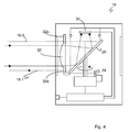
- Fig. 4
- eine Schnittdarstellung einer weiteren Ausführungsform des erfindungsgemäßen Laserscanners.
- Fig. 1
- a schematic sectional view of an embodiment of the laser scanner;
- Fig. 2
- a frontal view of a receiving optics and the light emitting unit according to
FIG. 1 ; - Fig. 3a to 3c
- Views in the direction of the received light beams on the deflection unit;
- Fig. 4
- a sectional view of another embodiment of the laser scanner according to the invention.
Das remittierte Licht gelangt wieder zu dem Scanner 10 zurück, wird über die Ablenkeinheit 20 und durch eine Empfangsoptik 32 auf einen Lichtempfänger 34, beispielsweise einer Photodiode, geführt und dort detektiert. Der von der Empfangsoptik 32 definierte Empfangslichtbereich ist durch seine Randstrahlen 30 dargestellt. Der Lichtempfänger 34 erzeugt aus den von dem Objekt in dem Überwachungsbereich 22 remittierten Sendelichtpulsen entsprechende Empfangssignale, die über eine Leitung 36 an eine Auswerteeinheit 38 geführt werden. Anhand des Empfangssignals des Lichtempfängers 34 kann aus der Winkelstellung der Ablenkeinheit 20 mittels des Encoders 28 auf die Winkellage erfasster Objekte in dem Überwachungsbereich 22 geschlossen werden.The remitted light returns to the
Zusätzlich wird in der Auswerteeinheit 38 die Laufzeit der einzelnen Laserlichtpulse von ihrem Aussenden bis zu dem Empfang nach Reflexion an dem Objekt in dem Überwachungsbereich 22 ermittelt. Aus der Lichtlaufzeit wird unter Verwendung der Lichtgeschwindigkeit auf die Entfernung des Objektes von dem Sensor 10 geschlossen. Dafür ist die Auswerteeinheit 38 mit den Laserdioden 18-1 bis 18-4, dem Lichtempfänger 34, dem Motor 24 und dem Encoder 28 verbunden. Somit stehen über Winkel und Entfernung zweidimensionale Polarkoordinaten aller Objekte in dem Überwachungsbereich 22 zur Verfügung.In addition, in the
Wird in der Auswerteeinheit 38 das detektierte Remissionslicht einem unzulässigen Objekt in einem vorgegebenen Schutzfeld, das innerhalb des Überwachungsbereichs 22 gelegen ist, zugeordnet, kann ein Sicherheitsschaltsignal über einen fehlersicheren Ausgang 40 (auch OSSD genannt, Output Signal Switching Device) bereitgestellt werden. Das Sicherheitssignal löst beispielsweise einen Nothalt einer angeschlossenen und von dem Sensor 10 überwachten Maschine aus. Die Auswertungseinheit 38 vergleicht dazu die Objektpositionen mit dem Schutzfeld, dessen Geometrie in der Auswertungseinheit 38 durch entsprechende Parameter vorgegeben oder konfiguriert ist. Damit erkennt die Auswertungseinheit 38, ob ein Schutzfeld verletzt ist, also ob sich ein unzulässiges Objekt darin befindet, und schaltet je nach Ergebnis den fehlersicheren Ausgang 40.If in the
Alle genannten Funktionskomponenten sind in einem Gehäuse 38 angeordnet, das im Bereich des Lichtaus- und Lichteintritts eine Frontscheibe 44 aufweist. Die Frontscheibe 44 ist im Wesentlichen zylindrisch ausgebildet, um einen großen, wenn möglich 360° Sichtbereich zu erlauben.All mentioned functional components are arranged in a
In den
Die Laserdioden 18-1 bis 18-4 werden von einer Laserdiodensteuereinheit 48 angesteuert. Diese kann so ausgebildet oder programmierbar sein, dass alle Laserdioden gleichzeitig pulsen und/oder dass jede einzelne Laserdiode separat ansteuerbar ist.The laser diodes 18-1 to 18-4 are driven by a laser diode control unit 48. This can be designed or programmable so that all laser diodes pulse simultaneously and / or that each individual laser diode can be controlled separately.
Durch eine anpassbare Gesamtsendeleistung bei separater Ansteuerung kann die Dynamikanforderung an die Empfängerelektronik reduziert werden wie eingangs erläutert.Due to an adaptable total transmission power with separate control, the dynamic demand can be reduced to the receiver electronics as explained above.
Des Weiteren ist eine Verschmutzungsüberwachungseinheit 50 vorgesehen, mit der eine Überwachung der Frontscheibe 44 auf Verschmutzung möglich ist. Dazu werden die Laserdioden 18-1 bis 18-4 von der Laserdiodensteuereinheit 46 unmittelbar nacheinander angesteuert und die Remissionssignale von diesen zwei aufeinanderfolgenden Pulsen unterschiedlicher Laserdioden verglichen. Da die einzelnen Laserdioden die Frontscheibe zwar an unterschiedlichen Orten durchstrahlen aber dennoch fast dieselbe Objektstelle antasten, lässt sich aus dem Vergleich des Remissionslichts der beiden Pulse eine inhomogene Verschmutzung der Frontscheibe ermitteln.Furthermore, a
Die einzelnen Laserdioden können sich auch hinsichtlich ihrer Emissionswellenlänge unterscheiden: z. B. kann eine Laserdiode im sichtbaren Spektralbereich und die übrigen bei ca. 900nm emittieren.The individual laser diodes can also differ in terms of their emission wavelength: z. B. can emit a laser diode in the visible spectral range and the rest at about 900nm.
In einer weiteren Ausführungsform, die in
Damit die Sendelichtstrahlen 16-1 bis 16-4 aber keine Strahlformung erfahren, weist die Empfangsoptik 32 zusätzlich zu der optisch wirksamen Fläche, beispielsweise eine Sammellinse, ein umlaufendes planparalles Ringfenster 32a auf.However, so that the transmitted light beams 16-1 to 16-4 experience no beam shaping, the receiving
Bei einer Variante dieser Ausführungsform sind die Empfangsoptik und der Drehspiegel monolithisch oder über einen schmalen Galgen miteinander verbunden, so dass die Sendelichtstrahlen zwischen dem Drehspiegel und der Frontscheibe an der Empfangsoptik vorbei verlaufen. Das Ringfenster 32a entfällt in dieser Variante, die den Vorteil einer hohen Kanaltrennung zwischen dem Sende- und dem Empfangslicht hat.In a variant of this embodiment, the receiving optics and the rotating mirror are monolithically connected to each other or via a narrow gallows, so that the transmitted light beams pass between the rotating mirror and the windscreen on the receiving optics. The
In einer weiteren, nicht dargestellten Ausführungsform ist die Ablenkeinheit als Hohlspiegel ausgebildet. Dann kann auf die Empfangsoptik 32 verzichtet werden und weiterer Bauraum gewonnen werden. Damit die Sendelichtstrahlen aber weiterhin in die korrekte Richtung um 90° umgelenkt werden, weist der Hohlspiegel in dem Ringbereich, in dem die Sendelichtstrahlen auftreffen, eine planparallele Ringscheibe auf.In another embodiment, not shown, the deflection unit is designed as a concave mirror. Then can be dispensed with the receiving
Claims (8)
Priority Applications (1)
| Application Number | Priority Date | Filing Date | Title |
|---|---|---|---|
| EP10160720A EP2381268B1 (en) | 2010-04-22 | 2010-04-22 | Security laser scanner |
Applications Claiming Priority (1)
| Application Number | Priority Date | Filing Date | Title |
|---|---|---|---|
| EP10160720A EP2381268B1 (en) | 2010-04-22 | 2010-04-22 | Security laser scanner |
Publications (2)
| Publication Number | Publication Date |
|---|---|
| EP2381268A1 true EP2381268A1 (en) | 2011-10-26 |
| EP2381268B1 EP2381268B1 (en) | 2012-06-27 |
Family
ID=42937233
Family Applications (1)
| Application Number | Title | Priority Date | Filing Date |
|---|---|---|---|
| EP10160720A Active EP2381268B1 (en) | 2010-04-22 | 2010-04-22 | Security laser scanner |
Country Status (1)
| Country | Link |
|---|---|
| EP (1) | EP2381268B1 (en) |
Cited By (8)
| Publication number | Priority date | Publication date | Assignee | Title |
|---|---|---|---|---|
| DE102011000978A1 (en) | 2011-02-28 | 2012-08-30 | Sick Ag | Optoelectronic sensor, particularly laser scanner for use in security systems for monitoring source of danger, has optical element, which is arranged downstream to light transmitter |
| EP2682780A1 (en) * | 2012-07-04 | 2014-01-08 | Sick Ag | Method for securely detecting and positioning objects and safety device |
| WO2019030015A1 (en) * | 2017-08-08 | 2019-02-14 | Robert Bosch Gmbh | Sensor apparatus for detecting an object |
| DE102018101846A1 (en) | 2018-01-26 | 2019-08-01 | Sick Ag | Optoelectronic sensor and method for detecting objects |
| CN110531369A (en) * | 2018-05-25 | 2019-12-03 | 深圳市速腾聚创科技有限公司 | A kind of solid-state laser radar |
| CN111273254A (en) * | 2018-12-04 | 2020-06-12 | 苏州旭创科技有限公司 | Laser radar transmitting device and laser radar |
| CN111273255A (en) * | 2018-12-04 | 2020-06-12 | 苏州旭创科技有限公司 | Laser radar transmitting device and laser radar |
| CN111766586A (en) * | 2019-03-29 | 2020-10-13 | 宁波舜宇车载光学技术有限公司 | Laser radar detection system and laser radar detection method |
Families Citing this family (2)
| Publication number | Priority date | Publication date | Assignee | Title |
|---|---|---|---|---|
| DE102017105994A1 (en) | 2017-03-21 | 2018-09-27 | Valeo Schalter Und Sensoren Gmbh | Transmission device for an optical detection device of a motor vehicle with VCSEL laser diodes, optical detection device, driver assistance system and motor vehicle |
| WO2023178108A1 (en) * | 2022-03-18 | 2023-09-21 | Motional Ad Llc | False signal reducing lidar window |
Citations (5)
| Publication number | Priority date | Publication date | Assignee | Title |
|---|---|---|---|---|
| DE4340756A1 (en) | 1992-12-08 | 1994-06-09 | Sick Optik Elektronik Erwin | Laser range finder, e.g. for driverless transport system - measures distance using pulse travel time and light deflection angle to determine position of object in measuring region |
| US5455669A (en) * | 1992-12-08 | 1995-10-03 | Erwin Sick Gmbh Optik-Elektronik | Laser range finding apparatus |
| EP0897120A2 (en) * | 1997-08-13 | 1999-02-17 | Schmersal-EOT GmbH & Co. KG | Apparatus for localisation of objects penetrating a monitored space |
| US6153878A (en) * | 1997-08-13 | 2000-11-28 | Schmersal-Eot Gmbh & Co. Kg | Device for locating objects penetrating into a region of space to be monitored |
| DE10244641A1 (en) | 2002-09-25 | 2004-04-08 | Ibeo Automobile Sensor Gmbh | Optoelectronic position monitoring system for road vehicle has two pulsed lasers, sensor and mechanical scanner with mirror at 45 degrees on shaft with calibration disk driven by electric motor |
-
2010
- 2010-04-22 EP EP10160720A patent/EP2381268B1/en active Active
Patent Citations (5)
| Publication number | Priority date | Publication date | Assignee | Title |
|---|---|---|---|---|
| DE4340756A1 (en) | 1992-12-08 | 1994-06-09 | Sick Optik Elektronik Erwin | Laser range finder, e.g. for driverless transport system - measures distance using pulse travel time and light deflection angle to determine position of object in measuring region |
| US5455669A (en) * | 1992-12-08 | 1995-10-03 | Erwin Sick Gmbh Optik-Elektronik | Laser range finding apparatus |
| EP0897120A2 (en) * | 1997-08-13 | 1999-02-17 | Schmersal-EOT GmbH & Co. KG | Apparatus for localisation of objects penetrating a monitored space |
| US6153878A (en) * | 1997-08-13 | 2000-11-28 | Schmersal-Eot Gmbh & Co. Kg | Device for locating objects penetrating into a region of space to be monitored |
| DE10244641A1 (en) | 2002-09-25 | 2004-04-08 | Ibeo Automobile Sensor Gmbh | Optoelectronic position monitoring system for road vehicle has two pulsed lasers, sensor and mechanical scanner with mirror at 45 degrees on shaft with calibration disk driven by electric motor |
Cited By (12)
| Publication number | Priority date | Publication date | Assignee | Title |
|---|---|---|---|---|
| DE102011000978A1 (en) | 2011-02-28 | 2012-08-30 | Sick Ag | Optoelectronic sensor, particularly laser scanner for use in security systems for monitoring source of danger, has optical element, which is arranged downstream to light transmitter |
| EP2682780A1 (en) * | 2012-07-04 | 2014-01-08 | Sick Ag | Method for securely detecting and positioning objects and safety device |
| EP2682780B1 (en) | 2012-07-04 | 2014-04-23 | Sick Ag | Method for securely detecting and positioning objects and safety device |
| WO2019030015A1 (en) * | 2017-08-08 | 2019-02-14 | Robert Bosch Gmbh | Sensor apparatus for detecting an object |
| US11802941B2 (en) | 2017-08-08 | 2023-10-31 | Robert Bosch Gmbh | Sensor apparatus for detecting an object |
| DE102018101846A1 (en) | 2018-01-26 | 2019-08-01 | Sick Ag | Optoelectronic sensor and method for detecting objects |
| US11914074B2 (en) | 2018-01-26 | 2024-02-27 | Sick Ag | Optoelectronic sensor and method for the detection of objects |
| CN110531369A (en) * | 2018-05-25 | 2019-12-03 | 深圳市速腾聚创科技有限公司 | A kind of solid-state laser radar |
| CN110531369B (en) * | 2018-05-25 | 2021-11-30 | 深圳市速腾聚创科技有限公司 | Solid-state laser radar |
| CN111273254A (en) * | 2018-12-04 | 2020-06-12 | 苏州旭创科技有限公司 | Laser radar transmitting device and laser radar |
| CN111273255A (en) * | 2018-12-04 | 2020-06-12 | 苏州旭创科技有限公司 | Laser radar transmitting device and laser radar |
| CN111766586A (en) * | 2019-03-29 | 2020-10-13 | 宁波舜宇车载光学技术有限公司 | Laser radar detection system and laser radar detection method |
Also Published As
| Publication number | Publication date |
|---|---|
| EP2381268B1 (en) | 2012-06-27 |
Similar Documents
| Publication | Publication Date | Title |
|---|---|---|
| EP2381268B1 (en) | Security laser scanner | |
| EP2482094B1 (en) | Distance measuring opto-electronic sensor and object detection method | |
| DE4340756C5 (en) | Laser range finding device | |
| DE102012102395B3 (en) | Optoelectronic sensor, particularly laser scanner, for detecting objects and measuring contamination, has test light detector arranged on side of front panel like reflector such that test light path of reflector guides over reflection | |
| EP2124069B1 (en) | Omnidirectional Lidar system | |
| EP2378309B1 (en) | Optoelectronic sensor and method for recording information about objects in a monitoring area | |
| EP3078985B1 (en) | Optoelectronic sensor and method for transmission monitoring a windshield | |
| DE4345448C2 (en) | Laser range finder, e.g. for driverless transport system | |
| EP2645125B1 (en) | Laser scanner and method for detecting objects in a surveillance area | |
| EP2447733B1 (en) | Optoelectronic sensor | |
| EP3136127A1 (en) | Distance sensor and method with a distance sensor | |
| EP2927711A1 (en) | Laser scanner and method for the reliable detection of objects | |
| EP1543344A2 (en) | Optoelectronic detection device | |
| EP2296002A1 (en) | Opto-electronic scanner for range determination in azimuth and elevation | |
| EP3388857B1 (en) | Laser scanner and method for testing its functional capability | |
| DE102011000978A1 (en) | Optoelectronic sensor, particularly laser scanner for use in security systems for monitoring source of danger, has optical element, which is arranged downstream to light transmitter | |
| EP3699638B1 (en) | Optoelectronic sensor and method for detecting an object | |
| EP2375266B1 (en) | Opto-electronic sensor and securing method | |
| EP3078984B1 (en) | Optoelectronic sensor and method for detecting objects in a surveillance area | |
| EP1780559B1 (en) | Optical sensor | |
| EP2703837A1 (en) | Safety laser scanner | |
| EP2637036B1 (en) | Ancillary module for setting on an optical sensor and method for operating an optical sensor | |
| EP4071503B1 (en) | Optoelectronic sensor and method for detecting objects | |
| EP3699637B1 (en) | Optoelectronic sensor and method for detecting an object | |
| DE202012101007U1 (en) | Optoelectronic sensor |
Legal Events
| Date | Code | Title | Description |
|---|---|---|---|
| AK | Designated contracting states |
Kind code of ref document: A1 Designated state(s): AT BE BG CH CY CZ DE DK EE ES FI FR GB GR HR HU IE IS IT LI LT LU LV MC MK MT NL NO PL PT RO SE SI SK SM TR |
|
| AX | Request for extension of the european patent |
Extension state: AL BA ME RS |
|
| PUAI | Public reference made under article 153(3) epc to a published international application that has entered the european phase |
Free format text: ORIGINAL CODE: 0009012 |
|
| 17P | Request for examination filed |
Effective date: 20111031 |
|
| RIC1 | Information provided on ipc code assigned before grant |
Ipc: G01S 17/02 20060101ALI20111207BHEP Ipc: G01S 7/483 20060101ALI20111207BHEP Ipc: G01S 7/481 20060101AFI20111207BHEP |
|
| GRAP | Despatch of communication of intention to grant a patent |
Free format text: ORIGINAL CODE: EPIDOSNIGR1 |
|
| GRAS | Grant fee paid |
Free format text: ORIGINAL CODE: EPIDOSNIGR3 |
|
| GRAA | (expected) grant |
Free format text: ORIGINAL CODE: 0009210 |
|
| AK | Designated contracting states |
Kind code of ref document: B1 Designated state(s): AT BE BG CH CY CZ DE DK EE ES FI FR GB GR HR HU IE IS IT LI LT LU LV MC MK MT NL NO PL PT RO SE SI SK SM TR |
|
| REG | Reference to a national code |
Ref country code: GB Ref legal event code: FG4D Free format text: NOT ENGLISH |
|
| REG | Reference to a national code |
Ref country code: CH Ref legal event code: EP |
|
| REG | Reference to a national code |
Ref country code: AT Ref legal event code: REF Ref document number: 564504 Country of ref document: AT Kind code of ref document: T Effective date: 20120715 |
|
| REG | Reference to a national code |
Ref country code: IE Ref legal event code: FG4D Free format text: LANGUAGE OF EP DOCUMENT: GERMAN |
|
| REG | Reference to a national code |
Ref country code: DE Ref legal event code: R096 Ref document number: 502010000947 Country of ref document: DE Effective date: 20120823 |
|
| PG25 | Lapsed in a contracting state [announced via postgrant information from national office to epo] |
Ref country code: SE Free format text: LAPSE BECAUSE OF FAILURE TO SUBMIT A TRANSLATION OF THE DESCRIPTION OR TO PAY THE FEE WITHIN THE PRESCRIBED TIME-LIMIT Effective date: 20120627 Ref country code: NO Free format text: LAPSE BECAUSE OF FAILURE TO SUBMIT A TRANSLATION OF THE DESCRIPTION OR TO PAY THE FEE WITHIN THE PRESCRIBED TIME-LIMIT Effective date: 20120927 Ref country code: FI Free format text: LAPSE BECAUSE OF FAILURE TO SUBMIT A TRANSLATION OF THE DESCRIPTION OR TO PAY THE FEE WITHIN THE PRESCRIBED TIME-LIMIT Effective date: 20120627 Ref country code: LT Free format text: LAPSE BECAUSE OF FAILURE TO SUBMIT A TRANSLATION OF THE DESCRIPTION OR TO PAY THE FEE WITHIN THE PRESCRIBED TIME-LIMIT Effective date: 20120627 |
|
| REG | Reference to a national code |
Ref country code: NL Ref legal event code: VDEP Effective date: 20120627 |
|
| REG | Reference to a national code |
Ref country code: LT Ref legal event code: MG4D Effective date: 20120627 |
|
| PG25 | Lapsed in a contracting state [announced via postgrant information from national office to epo] |
Ref country code: SI Free format text: LAPSE BECAUSE OF FAILURE TO SUBMIT A TRANSLATION OF THE DESCRIPTION OR TO PAY THE FEE WITHIN THE PRESCRIBED TIME-LIMIT Effective date: 20120627 Ref country code: GR Free format text: LAPSE BECAUSE OF FAILURE TO SUBMIT A TRANSLATION OF THE DESCRIPTION OR TO PAY THE FEE WITHIN THE PRESCRIBED TIME-LIMIT Effective date: 20120928 Ref country code: LV Free format text: LAPSE BECAUSE OF FAILURE TO SUBMIT A TRANSLATION OF THE DESCRIPTION OR TO PAY THE FEE WITHIN THE PRESCRIBED TIME-LIMIT Effective date: 20120627 Ref country code: HR Free format text: LAPSE BECAUSE OF FAILURE TO SUBMIT A TRANSLATION OF THE DESCRIPTION OR TO PAY THE FEE WITHIN THE PRESCRIBED TIME-LIMIT Effective date: 20120627 |
|
| PG25 | Lapsed in a contracting state [announced via postgrant information from national office to epo] |
Ref country code: IS Free format text: LAPSE BECAUSE OF FAILURE TO SUBMIT A TRANSLATION OF THE DESCRIPTION OR TO PAY THE FEE WITHIN THE PRESCRIBED TIME-LIMIT Effective date: 20121027 Ref country code: CY Free format text: LAPSE BECAUSE OF FAILURE TO SUBMIT A TRANSLATION OF THE DESCRIPTION OR TO PAY THE FEE WITHIN THE PRESCRIBED TIME-LIMIT Effective date: 20120627 Ref country code: SK Free format text: LAPSE BECAUSE OF FAILURE TO SUBMIT A TRANSLATION OF THE DESCRIPTION OR TO PAY THE FEE WITHIN THE PRESCRIBED TIME-LIMIT Effective date: 20120627 Ref country code: RO Free format text: LAPSE BECAUSE OF FAILURE TO SUBMIT A TRANSLATION OF THE DESCRIPTION OR TO PAY THE FEE WITHIN THE PRESCRIBED TIME-LIMIT Effective date: 20120627 Ref country code: EE Free format text: LAPSE BECAUSE OF FAILURE TO SUBMIT A TRANSLATION OF THE DESCRIPTION OR TO PAY THE FEE WITHIN THE PRESCRIBED TIME-LIMIT Effective date: 20120627 Ref country code: CZ Free format text: LAPSE BECAUSE OF FAILURE TO SUBMIT A TRANSLATION OF THE DESCRIPTION OR TO PAY THE FEE WITHIN THE PRESCRIBED TIME-LIMIT Effective date: 20120627 |
|
| PG25 | Lapsed in a contracting state [announced via postgrant information from national office to epo] |
Ref country code: PL Free format text: LAPSE BECAUSE OF FAILURE TO SUBMIT A TRANSLATION OF THE DESCRIPTION OR TO PAY THE FEE WITHIN THE PRESCRIBED TIME-LIMIT Effective date: 20120627 Ref country code: IT Free format text: LAPSE BECAUSE OF FAILURE TO SUBMIT A TRANSLATION OF THE DESCRIPTION OR TO PAY THE FEE WITHIN THE PRESCRIBED TIME-LIMIT Effective date: 20120627 Ref country code: PT Free format text: LAPSE BECAUSE OF FAILURE TO SUBMIT A TRANSLATION OF THE DESCRIPTION OR TO PAY THE FEE WITHIN THE PRESCRIBED TIME-LIMIT Effective date: 20121029 |
|
| PG25 | Lapsed in a contracting state [announced via postgrant information from national office to epo] |
Ref country code: NL Free format text: LAPSE BECAUSE OF FAILURE TO SUBMIT A TRANSLATION OF THE DESCRIPTION OR TO PAY THE FEE WITHIN THE PRESCRIBED TIME-LIMIT Effective date: 20120627 |
|
| PG25 | Lapsed in a contracting state [announced via postgrant information from national office to epo] |
Ref country code: DK Free format text: LAPSE BECAUSE OF FAILURE TO SUBMIT A TRANSLATION OF THE DESCRIPTION OR TO PAY THE FEE WITHIN THE PRESCRIBED TIME-LIMIT Effective date: 20120627 |
|
| PLBE | No opposition filed within time limit |
Free format text: ORIGINAL CODE: 0009261 |
|
| STAA | Information on the status of an ep patent application or granted ep patent |
Free format text: STATUS: NO OPPOSITION FILED WITHIN TIME LIMIT |
|
| 26N | No opposition filed |
Effective date: 20130328 |
|
| REG | Reference to a national code |
Ref country code: DE Ref legal event code: R097 Ref document number: 502010000947 Country of ref document: DE Effective date: 20130328 |
|
| PG25 | Lapsed in a contracting state [announced via postgrant information from national office to epo] |
Ref country code: BG Free format text: LAPSE BECAUSE OF FAILURE TO SUBMIT A TRANSLATION OF THE DESCRIPTION OR TO PAY THE FEE WITHIN THE PRESCRIBED TIME-LIMIT Effective date: 20120927 |
|
| BERE | Be: lapsed |
Owner name: SICK A.G. Effective date: 20130430 |
|
| PG25 | Lapsed in a contracting state [announced via postgrant information from national office to epo] |
Ref country code: ES Free format text: LAPSE BECAUSE OF FAILURE TO SUBMIT A TRANSLATION OF THE DESCRIPTION OR TO PAY THE FEE WITHIN THE PRESCRIBED TIME-LIMIT Effective date: 20121008 |
|
| PG25 | Lapsed in a contracting state [announced via postgrant information from national office to epo] |
Ref country code: MC Free format text: LAPSE BECAUSE OF FAILURE TO SUBMIT A TRANSLATION OF THE DESCRIPTION OR TO PAY THE FEE WITHIN THE PRESCRIBED TIME-LIMIT Effective date: 20120627 |
|
| REG | Reference to a national code |
Ref country code: IE Ref legal event code: MM4A |
|
| PG25 | Lapsed in a contracting state [announced via postgrant information from national office to epo] |
Ref country code: BE Free format text: LAPSE BECAUSE OF NON-PAYMENT OF DUE FEES Effective date: 20130430 |
|
| PG25 | Lapsed in a contracting state [announced via postgrant information from national office to epo] |
Ref country code: IE Free format text: LAPSE BECAUSE OF NON-PAYMENT OF DUE FEES Effective date: 20130422 |
|
| PG25 | Lapsed in a contracting state [announced via postgrant information from national office to epo] |
Ref country code: MT Free format text: LAPSE BECAUSE OF FAILURE TO SUBMIT A TRANSLATION OF THE DESCRIPTION OR TO PAY THE FEE WITHIN THE PRESCRIBED TIME-LIMIT Effective date: 20120627 |
|
| PG25 | Lapsed in a contracting state [announced via postgrant information from national office to epo] |
Ref country code: SM Free format text: LAPSE BECAUSE OF FAILURE TO SUBMIT A TRANSLATION OF THE DESCRIPTION OR TO PAY THE FEE WITHIN THE PRESCRIBED TIME-LIMIT Effective date: 20120627 |
|
| PG25 | Lapsed in a contracting state [announced via postgrant information from national office to epo] |
Ref country code: TR Free format text: LAPSE BECAUSE OF FAILURE TO SUBMIT A TRANSLATION OF THE DESCRIPTION OR TO PAY THE FEE WITHIN THE PRESCRIBED TIME-LIMIT Effective date: 20120627 |
|
| PG25 | Lapsed in a contracting state [announced via postgrant information from national office to epo] |
Ref country code: MK Free format text: LAPSE BECAUSE OF FAILURE TO SUBMIT A TRANSLATION OF THE DESCRIPTION OR TO PAY THE FEE WITHIN THE PRESCRIBED TIME-LIMIT Effective date: 20120627 Ref country code: LU Free format text: LAPSE BECAUSE OF NON-PAYMENT OF DUE FEES Effective date: 20130422 Ref country code: HU Free format text: LAPSE BECAUSE OF FAILURE TO SUBMIT A TRANSLATION OF THE DESCRIPTION OR TO PAY THE FEE WITHIN THE PRESCRIBED TIME-LIMIT; INVALID AB INITIO Effective date: 20100422 |
|
| REG | Reference to a national code |
Ref country code: FR Ref legal event code: PLFP Year of fee payment: 7 |
|
| REG | Reference to a national code |
Ref country code: AT Ref legal event code: MM01 Ref document number: 564504 Country of ref document: AT Kind code of ref document: T Effective date: 20150422 |
|
| PG25 | Lapsed in a contracting state [announced via postgrant information from national office to epo] |
Ref country code: AT Free format text: LAPSE BECAUSE OF NON-PAYMENT OF DUE FEES Effective date: 20150422 |
|
| REG | Reference to a national code |
Ref country code: FR Ref legal event code: PLFP Year of fee payment: 8 |
|
| REG | Reference to a national code |
Ref country code: FR Ref legal event code: PLFP Year of fee payment: 9 |
|
| PGFP | Annual fee paid to national office [announced via postgrant information from national office to epo] |
Ref country code: CH Payment date: 20190424 Year of fee payment: 10 |
|
| REG | Reference to a national code |
Ref country code: CH Ref legal event code: PL |
|
| PG25 | Lapsed in a contracting state [announced via postgrant information from national office to epo] |
Ref country code: LI Free format text: LAPSE BECAUSE OF NON-PAYMENT OF DUE FEES Effective date: 20200430 Ref country code: CH Free format text: LAPSE BECAUSE OF NON-PAYMENT OF DUE FEES Effective date: 20200430 |
|
| PGFP | Annual fee paid to national office [announced via postgrant information from national office to epo] |
Ref country code: GB Payment date: 20220425 Year of fee payment: 13 Ref country code: FR Payment date: 20220420 Year of fee payment: 13 |
|
| PGFP | Annual fee paid to national office [announced via postgrant information from national office to epo] |
Ref country code: DE Payment date: 20230418 Year of fee payment: 14 |
|
| GBPC | Gb: european patent ceased through non-payment of renewal fee |
Effective date: 20230422 |
|
| PG25 | Lapsed in a contracting state [announced via postgrant information from national office to epo] |
Ref country code: GB Free format text: LAPSE BECAUSE OF NON-PAYMENT OF DUE FEES Effective date: 20230422 |
|
| PG25 | Lapsed in a contracting state [announced via postgrant information from national office to epo] |
Ref country code: GB Free format text: LAPSE BECAUSE OF NON-PAYMENT OF DUE FEES Effective date: 20230422 Ref country code: FR Free format text: LAPSE BECAUSE OF NON-PAYMENT OF DUE FEES Effective date: 20230430 |