EP2381110A2 - Kraftfahrzeugklimaanlage - Google Patents
Kraftfahrzeugklimaanlage Download PDFInfo
- Publication number
- EP2381110A2 EP2381110A2 EP11162589A EP11162589A EP2381110A2 EP 2381110 A2 EP2381110 A2 EP 2381110A2 EP 11162589 A EP11162589 A EP 11162589A EP 11162589 A EP11162589 A EP 11162589A EP 2381110 A2 EP2381110 A2 EP 2381110A2
- Authority
- EP
- European Patent Office
- Prior art keywords
- screen
- air conditioning
- ring
- conditioning system
- hub
- Prior art date
- Legal status (The legal status is an assumption and is not a legal conclusion. Google has not performed a legal analysis and makes no representation as to the accuracy of the status listed.)
- Granted
Links
Images

Classifications
-
- F—MECHANICAL ENGINEERING; LIGHTING; HEATING; WEAPONS; BLASTING
- F04—POSITIVE - DISPLACEMENT MACHINES FOR LIQUIDS; PUMPS FOR LIQUIDS OR ELASTIC FLUIDS
- F04D—NON-POSITIVE-DISPLACEMENT PUMPS
- F04D25/00—Pumping installations or systems
- F04D25/02—Units comprising pumps and their driving means
- F04D25/06—Units comprising pumps and their driving means the pump being electrically driven
- F04D25/0606—Units comprising pumps and their driving means the pump being electrically driven the electric motor being specially adapted for integration in the pump
-
- F—MECHANICAL ENGINEERING; LIGHTING; HEATING; WEAPONS; BLASTING
- F04—POSITIVE - DISPLACEMENT MACHINES FOR LIQUIDS; PUMPS FOR LIQUIDS OR ELASTIC FLUIDS
- F04D—NON-POSITIVE-DISPLACEMENT PUMPS
- F04D29/00—Details, component parts, or accessories
- F04D29/26—Rotors specially for elastic fluids
- F04D29/28—Rotors specially for elastic fluids for centrifugal or helico-centrifugal pumps for radial-flow or helico-centrifugal pumps
- F04D29/281—Rotors specially for elastic fluids for centrifugal or helico-centrifugal pumps for radial-flow or helico-centrifugal pumps for fans or blowers
- F04D29/282—Rotors specially for elastic fluids for centrifugal or helico-centrifugal pumps for radial-flow or helico-centrifugal pumps for fans or blowers the leading edge of each vane being substantially parallel to the rotation axis
-
- F—MECHANICAL ENGINEERING; LIGHTING; HEATING; WEAPONS; BLASTING
- F04—POSITIVE - DISPLACEMENT MACHINES FOR LIQUIDS; PUMPS FOR LIQUIDS OR ELASTIC FLUIDS
- F04D—NON-POSITIVE-DISPLACEMENT PUMPS
- F04D29/00—Details, component parts, or accessories
- F04D29/70—Suction grids; Strainers; Dust separation; Cleaning
- F04D29/701—Suction grids; Strainers; Dust separation; Cleaning especially adapted for elastic fluid pumps
- F04D29/706—Humidity separation
Definitions
- the invention relates to an automotive air conditioning system according to the preamble of claim 1.
- the motor vehicle air conditioning system generally comprises a refrigerant evaporator for cooling the air and a heating device for heating the air.
- a blower serves to circulate or convey the air through the motor vehicle air conditioning system. The air is sucked in from the surroundings of the motor vehicle or from the interior of the motor vehicle, then passed to the refrigerant evaporator and the heating device and subsequently supplied to the motor vehicle interior.
- the fan is arranged within a fan housing and has an impeller, a drive shaft and an electric motor. By means of the electric motor, the impeller is driven, so that on the impeller trained blades on a hub can promote or circulate the air.
- the object of the present invention is therefore to provide an automotive air conditioning system in which the electric motor is protected against water and moisture and a freezing of the impeller is substantially excluded.
- an automotive air conditioning system comprising a housing, a fan with an impeller, a drive shaft and an electric motor, wherein the impeller has a hub and blades for circulating the air and the electric motor is arranged below the impeller, preferably a refrigerant evaporator for cooling an air to be supplied to a vehicle interior, a heater for heating the air to be supplied to the vehicle interior, the impeller being provided with a liquid-tight closed screen for shielding water from the electric motor.
- the formation of the impeller, in particular the hub, above the electric motor as a liquid-tight closed screen causes that guided from above toward the electric motor water, especially in the form of steam, mist or water droplets, does not reach the electric motor and the screen radially is derived to the outside.
- the liquid-tight closed screen has no opening, so that in a direction from top to bottom of the screen is liquid-tight and thus no liquid can be passed through the screen.
- the hub is formed as the liquid-tight closed screen and / or the impeller is formed in the axial direction of the drive shaft above the electric motor as the liquid-tight closed screen and / or the hub is at a projection portion of the electric motor to the hub parallel to an axis of the drive shaft is formed as a fluid-tight closed shield and preferably the hub is additionally formed at a radial distance of less than 5 cm, 2 cm or 1 cm to the projection portion as the liquid-tight closed screen.
- the impeller is formed radially outside of the electric motor as the liquid-tight closed screen
- the screen is formed as a disk or a dome
- the screen designed as a dome has a top-side outward radial direction outward, in particular a continuous downward gradient.
- the shield formed as a dome in the radial direction outwards on the underside, in particular continuous slope.
- the screen has on one upper side a convex surface and / or on one lower side a concave surface.
- the drive shaft is oriented substantially vertically.
- a substantially vertical orientation of the drive shaft preferably means that the drive shaft is aligned with a deviation of less than 30 °, 20 °, 10 °, 5 ° or 2 ° to a vertical plane or vertical line.
- the liquid-tight screen is formed at a radial end portion as a ring and the slope of the ring is upper side smaller than the slope of the screen within the ring on the upper side, in particular as the slope of the screen on the upper side within the ring at a radial distance of less than half the radius of the screen.
- the ring thus also has a slight downward gradient on the upper side, so that water which flows out of the screen in the area inside the ring to the ring can also flow out radially on the ring to the outside.
- the liquid-tight screen is formed at a radial end portion as a ring and the slope of the ring underside is smaller than the slope of the screen within the ring below, especially as the slope of the screen below the inside of the ring at a radial distance of less as half the radius of the screen
- the liquid-tight screen in particular the ring, and / or the blades are provided on the underside in a radial end region with an annular drip nose.
- annular drip the water flowing from the top of the ring to the bottom of the ring can drip off, so that this water drips down deliberately at the drip tip below the impeller, so that a targeted and controlled discharge of the water is allowed.
- the drive shaft is fastened to a fixing opening in the hub
- the fixation opening is formed as a bore completely piercing the hub and the drive shaft with respect to the hub is sealed liquid-tight at the bore or the fixation opening is formed as a downwardly formed bore and above the fixation opening of the liquid-tight screen of the hub is continued and / or the impeller is integrally formed, in particular made of plastic.
- the hub or the screen is thus formed liquid-tight in the region of the fixing opening with the drive shaft arranged therein
- the electric motor is fastened to the housing by means of a motor holder that encloses the electric motor at least partially, in particular completely, and / or the electric motor is an electrically commutated, brushless motor.
- the motor holder in the radial direction outwards on the top and / or bottom side, in particular continuous slope on.
- impinging water on the motor holder can be discharged radially outward, so that no water can reach the electric motor arranged radially inside the motor holder,
- the gradient of the motor holder is formed in a ring portion below the liquid-tight screen and preferably additionally radially outside of the ring portion.
- At least one annular step is formed in the ring portion and preferably outside the ring portion
- the refrigerant evaporator and the, preferably electrical, heating device are arranged within the housing of the motor vehicle air conditioning system.
- the motor vehicle air conditioning system has at least one channel for passing air through.
- the motor vehicle air conditioning system comprises at least one air filter.
- the refrigerant evaporator and / or the, preferably electrical, heating device and / or the at least one air filter are arranged within the at least one channel.
- the at least one air filter in the flow direction of the air upstream of the fan is arranged as a suction-side air filter and / or in the flow direction of the air downstream of the fan as a pressure-side air filter.
- the motor vehicle air conditioning system comprises at least one air guiding device, for. B. at least one air damper and / or at least one screen and / or at least one roller tape, on, by means of or to which the air quantity controllable by the at least one channel can be controlled
- the housing of the motor vehicle air conditioning at least partially made of plastic.
- the at least one channel for the passage of air from a wall of the housing is limited
- a refrigerant evaporator for cooling the air to be supplied to the vehicle interior, and a heater for heating the air to be supplied to the vehicle interior arranged.
- the refrigerant evaporator and the heating device are arranged inside a channel which is fired or restricted by the housing 2.
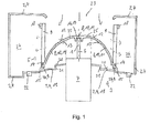
- the blower 3 has a blower housing 4 as part of the housing 2 of the motor vehicle air conditioner on.
- the fan housing 4 limits a flow space 24 and has a suction port 23 for sucking air, within the blower housing 4, an impeller 5, a drive shaft 6 and an electric motor 7 is arranged.
- the impeller 5 is mechanically connected to the electric motor 7, so that thereby the impeller 6 performs a rotational movement with a rotation axis as an axis 1 of the drive shaft 6 of the electric motor 7.
- the impeller 5 has a hub 8 with blades 9 arranged thereon ( Fig. 1 to 3 ).
- At the hub 8 is centrally formed as a bore 17 fixing opening 16 is present.
- the bore 17 has any cross-section, for example, it is circular, square or triangular.
- the drive shaft 6 is fixed ( Fig. 1 ).
- the hub 8 of the impeller 5 is formed as a screen 10 in the form of a dome 11.
- An upper side 12 and an underside 13 of the screen 10 has a gradient in the radial direction outward away from the axis 1.
- water impinging on the upper side 12 of the screen 10 or the hub 8 is conducted radially outwards to form a ring 14 at a radial end section of the screen 10.
- the blades 9 pierce the ring 14 slightly, so that even below the ring 14, a small portion of the blades 9 is present, which form a cooling trough 26 ( Fig. 1 to 3 ).
- the cooling flow 26 serves to circulate the air between the screen 10 and the electric motor 7 for cooling the electric motor 7.
- a completely circumferential stabilizing ring 18 is provided to fix or stabilize also at the upper end of the blades 9 to allow the blades 9.
- the upper Stabilisierurigsring 18 is in the view from below in Fig. 2 not shown.
- a projection section 25 of the electric motor 7 is formed on the hub 8. This projection is in Fig. 1 shown with two dashed lines from the electric motor 7 to the hub 8.
- the electric motor 7 is fixed by means of a ring-like motor holder 19 made of plastic and a tongue and groove connection 22 as a releasable connection means to the fan housing 4.
- the motor holder 19 has a gradient in a radial direction with increasing distance from the electric motor 7.
- an annular step 21 is formed on the motor holder 19.
- a top 20 of the motor holder 19 thus has from the electric motor 7 to the tongue and groove connection 22 on a slope.
- the sucked air is sucked down at the intake opening 23 substantially in a direction parallel to the axis 1 of the drive shaft 6 and then conveyed radially outward of the blades 9 with respect to the axis 1 into the flow space 24.
- In the air sucked through the suction port 23 may be water, for example in the form of vapor, mist or water droplets contained.
- the lower end of the blades 9 or the cooling trough 26 can likewise have the same geometry as the drip nose 15 (not shown) or the lower end of the blades 9 or the cooling trough 26 has a triangular shape (in FIG Fig. 1 shown in dashed lines) and thus also forms a triangular drip 15.
- This derived at the top 12 of the screen 10 drips water, especially at a standstill of the impeller 5, then controlled at the drip 15 on the top 20 of the motor holder 19. Due to the slope of the motor holder 19 at the top 20 of this water flows radially outward to the blower housing 4.
- a drain opening not shown, arranged for this water, so that controlled by this drain opening of this collected water can be derived from the automotive air conditioning.
- the hub 8 as the screen 10 thus protects the electric motor 7 from above in the direction of the electric motor 7 guided water. Due to the gradient of the motor holder 19 on the upper side 20, this water can not reach the electric motor 7 either.
- At the top 20 of the motor holder 19 befindliches water is not due to the formation of the stage 21 at a horizontal acceleration of the motor vehicle air conditioning, for example, when cornering, not passed to the electric motor 7, because such splash water can be prevented from the stage 21.
Landscapes
- Engineering & Computer Science (AREA)
- Mechanical Engineering (AREA)
- General Engineering & Computer Science (AREA)
- Structures Of Non-Positive Displacement Pumps (AREA)
Abstract
Description
- Die Erfindung betrifft eine Kraftfahrzeugklimaanlage gemäß dem Oberbegriff des Anspruches 1.
- Kraftfahrzeugklimaanlagen werden in Kraftfahrzeugen zum Kühlen und/oder Erwärmen von einem innenraum des Kraftfahrzeuges zuzuführender Luft eingesetzt. Die Kraftfahrzeugklimaanlage umfasst dabei im Allgemeinen einen Kältemittelverdampfer zum Kühlen der Luft und eine Heizeinrichtung zum Erwärmen der Luft. Ein Gebläse dient zum Umwälzen bzw. Fördern der Luft durch die Kraftfahrzeugklimaanlage Von dem Gebläse wird die Luft aus der Umgebung des Kraftfahrzeuges oder aus dem Innenraum des Kraftfahrzeuges angesaugt, anschließend zu dem Kältemittelverdampfer und der Heizeinrichtung geleitet und darauffolgend dem Kraftfahrzeuginnenraum zugeführt. Das Gebläse ist innerhalb eines Gebläsegehäuses angeordnet und weist dabei ein Laufrad, eine Antriebswelle und einen Elektromotor auf. Mittels des Elektromotors wird das Laufrad angetrieben, so dass an dem Laufrad ausgebildete Schaufeln an einer Nabe die Luft fördern bzw. umwälzen können.
- Beim Ansaugen der Luft durch das Gehäuse kann Wasser oder Feuchtigkeit, beispielsweise in Form von Dampf oder Nebel, zu dem Laufrad und dem Elektromotor gelangen und insbesondere den Elektromotor beschädigen. Auch bei der Anordnung eines saugseitigen Luftfilters in der Kraftfahrzeugklimaanlage kann Wasser oder Feuchtigkeit zu dem Laufrad oder dem Gebläse gelangen. Bei Temperaturen von weniger als 0°C besteht außerdem die Gefahr des Festfrierens des Laufrades an einem Motorhalter für den Elektromotor oder ein Festfrieren des Motors selbst
- Aus der
EP 1 106 837 A1 ist ein Gebläse für eine Kraftfahrzeugklimaanlage bekannt Dabei ist das Laufrad oberhalb des Elektromotors angeordnet. - Die Aufgabe der vorlegenden Erfindung besteht deshalb darin, eine Kraftfahrzeugklimaanlage zur Verfügung zu stellen, bei welcher der Elektromotor vor Wasser und Feuchtigkeit geschützt und ein Festfrieren des Laufrades im Wesentlichen ausgeschlossen ist.
- Diese Aufgabe wird gelöst mit einer Kraftfahrzeugklimaanlage, umfassend ein Gehäuse, ein Gebläse mit einem Laufrad, einer Antriebswelle und einem Elektromotor, wobei das Laufrad eine Nabe und Schaufeln zum Umwälzen der Luft aufweist und der Elektromotor unterhalb des Laufrades angeordnet ist, vorzugsweise einen Kältemittelverdampfer zum Kühlen einer einem Fahrzeuginnenraum zuzuführenden Luft, eine Heizeinrichtung zum Erwärmen der dem Fahrzeuginnenraum zuzuführenden Luft, wobei das Laufrad mit einem flüssigkeitsdichten geschlossenen Schirm versehen ist zur Abschirmung von Wasser von dem Elektromotor.
- Die Ausbildung des Laufrades, insbesondere der Nabe, oberhalb des Elektromotors als ein flüssigkeitsdichter geschlossener Schirm bewirkt, dass von oben in Richtung zu dem Elektromotor geführtes Wasser, insbesondere in Form von Dampf, Nebel oder Wassertropfen, nicht zu dem Elektromotor gelangt und von dem Schirm radial nach außen abgeleitet wird.
- In einer ergänzenden Ausgestaltung weist der flüssigkeitsdichte geschlossene Schirm keine Öffnung auf, so dass in einer Richtung von oben nach unten der Schirm flüssigkeitsdicht ist und somit durch den Schirm keine Flüssigkeit durchgeleitet werden kann.
- Insbesondere ist die Nabe als der flüssigkeitsdichte geschlossene Schirm ausgebildet und/oder das Laufrad ist in axialer Richtung der Antriebswelle oberhalb des Elektromotors als der flüssigkeitsdichte geschlossene Schirm ausgebildet und/oder die Nabe ist an einem Projektionsabschnitt des Elektromotors auf die Nabe parallel zu einer Achse der Antriebswelle als ein flüssigketisdichter geschlossener Schirm ausgebildet und vorzugsweise ist die Nabe zusätzlich in einem radialen Abstand von weniger als 5 cm, 2 cm oder 1 cm zu dem Projektionsabschnitt als der flüssigkeitsdichte geschlossene Schirm ausgebildet.
- ln einer zusätzlichen Ausgestaltung ist das Laufrad radial außerhalb des Elektromotors als der flüssigkeitsdichte geschlossene Schirm ausgebildet,
- In einer weiteren Ausgestaltung ist der Schirm als eine Scheibe oder ein Dom ausbildet
- In einer ergänzenden Ausführungsform weist der als Dom ausgebildete Schirm In radialer Richtung nach außen oberseitig ein, insbesondere stetiges, Gefälle auf.
- Vorzugsweise weist der als Dom ausgebildete Schirm in radialer Richtung nach außen unterseitig ein, insbesondere stetiges, Gefälle auf.
- In einer weiteren Ausführungsform weist der Schirm an einer Oberseite eine konvexe Oberfläche auf und/oder an einer Unterseite eine konkave Oberfläche.
- In einer Variante ist die Antriebswelle im Wesentlichen vertikal ausgerichtet.
- Eine im Wesentlichen vertikale Ausrichtung der Antriebswelle bedeutet vorzugsweise, dass die Antriebswelle mit einer Abweichung von weniger als 30°, 20°, 10°, 5° oder 2° zu einer vertikalen Ebene oder vertikale Gerade ausgerichtet ist.
- Zweckmäßig ist der flüssigkeitsdichte Schirm an einem radialen Endabschnitt als ein Ring ausgebildet und das Gefälle des Ringes ist oberseitig kleiner als das Gefälle des Schirmes innerhalb des Ringes oberseitig, insbesondere als das Gefälle des Schirmes oberseitig innerhalb des Ringes in einem radialen Abstand von weniger als der Hälfte des Radius des Schirmes. Der Ring weist somit auch an der Oberseite ein geringes Gefälle auf, so dass Wasser, welches aus dem Schirm im Bereich innerhalb des Ringes zu dem Ring strömt, auch am Ring radial nach außen abströmen kann.
- In einer weiteren Ausführungsform ist der flüssigkeitsdichte Schirm an einem radialen Endabschnitt als ein Ring ausgebildet und das Gefälle des Ringes unterseitig ist kleiner als das Gefälle des Schirmes innerhalb des Ringes unterseitig, insbesondere als das Gefälle des Schirmes untenseitig innerhalb des Ringes in einem radialen Abstand von weniger als der Hälfte des Radius des Schirmes
- Insbesondere sind der flüssigkeitsdichte Schirm, insbesondere der Ring, und/oder die Schaufeln unterseitig in einem radialen Endbereich mit einer ringförmigen Tropfnase versehen. An der ringförmigen Tropfnase kann das von der Oberseite des Ringes zu der Unterseite des Ringes strömende Wasser abtropfen, so dass dieses Wasser gezielt an der Tropfnase unterhalb des Laufrades nach unten abtropft, Damit soll ein gezieltes und kontrolliertes Ableiten des Wassers ermöglicht werden.
- In einer weiteren Ausgestaltung ist die Antriebswelle an einer Fixierungsöffnung in der Nabe befestigt,
- In einer weiteren Ausgestaltung ist die Fixierungsöffnung als eine die Nabe vollständig durchstoßende Bohrung ausgebildet und die Antriebswelle bezüglich der Nabe ist an der Bohrung flüssigkeitsdicht abgedichtet oder die Fixierungsöffnung ist als eine lediglich nach unten ausgebildete Bohrung ausgebildet und oberhalb der Fixierungsöffnung ist der flüssigkeitsdichte Schirm der Nabe fortgesetzt und/oder das Laufrad ist einteilig, insbesondere aus Kunststoff, ausgebildet. Die Nabe bzw. der Schirm ist damit auch im Bereich der Fixierungsöffnung mit der darin angeordneten Antriebswelle flüssigkeitsdicht ausgebildet
- In einer ergänzenden Variante ist der Elektromotor mit einem den Elektromotor wenigstens teilweise, insbesondere vollständig, umschließenden Motorhalter an dem Gehäuse befestigt und/oder der Elektromotor ist ein elektrisch kommutierter, bürstenloser Motor.
- In einer weiteren Variante weist der Motorhalter in radialer Richtung nach außen oberseitig und/oder unterseitig ein, insbesondere stetiges, Gefälle auf. Damit kann auf dem Motorhalter auftreffendes Wasser radial nach außen abgeleitet werden, so dass zu dem radial innerhalb des Motorhalters angeordneten Elektromotor kein Wasser gelangen kann,
- In einer weiteren Ausgestaltung ist das Gefälle des Motorhalters in einem Ringabschnitt unterhalb des flüssigkeitsdichten Schirmes ausgebildet und vorzugsweise zusätzlich radial außerhalb des Ringabschnittes.
- Insbesondere ist in dem Ringabschnitt und vorzugsweise außerhalb des Ringabschnittes wenigstens eine ringförmige Stufe ausgebildet
- In einer weiteren Ausgestaltung sind innerhalb des Gehäuses der Kraftfahrzeugklimaanlage der Kältemittelverdampfer und die, vorzugsweise elektrische, Heizeinrichtung angeordnet.
- In einer weiteren Ausgestaltung weist die Kraftfahrzeugklimaanlage wenigstens einen Kanal zum Durchleiten von Luft auf.
- Zweckmäßig umfasst die Kraftfahrzeugklimaanlage wenigstens einen Luftfilter.
- In einer Variante sind der Kältemittelverdampfer und/oder die, vorzugsweise elektrische, Heizeinrichtung und/oder der wenigstens eine Luftfilter innerhalb des wenigstens einen Kanales angeordnet.
- In einer weiteren Ausführungsform ist der wenigstens eine Luftfilter in Strömungsrichtung der Luft vor dem Gebläse als saugseitiger Luftfilter angeordnet und/oder in Strömungsrichtung der Luft nach dem Gebläse als druckseitiger Luftfilter.
- In einer ergänzenden Ausgestaltung weist die Kraftfahzeugklimaanlage wenigstens eine Luftleiteinrichtung, z. B. wenigstens eine Luftklappe und/oder wenigstens einen Schirm und/oder wenigstens ein Rollband, auf, mittels der oder denen die durch den wenigstens einen Kanal leitbare Luftmenge steuerbar ist
- insbesondere besteht das Gehäuse der Kraftfahrzeugklimaanlage wenigstens teilweise aus Kunststoff.
- Zweckmäßig ist der wenigstens eine Kanal zum Durchleiten von Luft von einer Wandung des Gehäuses begrenzt
- Im Nachfolgenden wird ein Ausführungsbeispiel der Erfindung unter Bezugnahme auf die beigefügten Zeichnungen näher beschrieben. Es zeigt:
-
Fig. 1 einen Querschnitt eines Gebläses einer Kraftfahrzeugklimaanlage, -
Fig.2 eine Bodenansicht des Laufrades des Gebläses gemäßFig. 1 und -
Fig.3 eine Seitenansicht des Laufrades des Gebläses gemäßFig. 1 . - Eine Kraftfahrzeugklimaanlage mit einem Gehäuse 2 dient zum Kühlen und/oder zum Erwärmen von einem Innenraum eines nicht dargestellten Kraftfahrzeuges zuzuführender Luft, Innerhalb des Gehäuses 2 der Kraftfahrzeugklimaanlage ist ein Kältemittelverdampfer zum Kühlen der dem Fahrzeuginnenraum zuzuführende Luft und eine Heizeinrichtung zum Erwärmen der dem Fahrzeuginnenraum zuzuführenden Luft angeordnet. Der Kältemittelverdampfer und die Heizeinrichtung sind dabei innerhalb eines von dem Gehäuse 2 eingeschossenen bzw. begrenzten Kanales angeordnet.
- Zum Umwälzen bzw. Fördern der Luft durch die Kraftfahrzeugklimaanlage ist diese ferner mit einem Gebläse 3 (
Fig.1 ) versehen. Das Gebläse 3 weist ein Gebläsegehäuse 4 als Teil des Gehäuses 2 der Kraftfahrzeugklimaanlage auf. Das Gebläsegehäuse 4 begrenzt dabei einen Strömungsraum 24 und weist eine Ansaugöffnung 23 zum Ansaugen von Luft auf, innerhalb des Gebläsegehäuses 4 ist ein Laufrad 5, eine Antriebswelle 6 und ein Elektromotor 7 angeordnet. Mittels der Antriebswelle 6 ist das Laufrad 5 mit dem Elektromotor 7 mechanisch verbunden, so dass dadurch das Laufrad 6 eine Rotationsbewegung mit einer Rotationsachse als einer Achse 1 der Antriebswelle 6 von dem Elektromotor 7 ausführt. Das Laufrad 5 weist eine Nabe 8 mit daran angeordneten Schaufeln 9 auf (Fig. 1 bis 3 ). An der Nabe 8 ist zentrisch eine als Bohrung 17 ausgebildete Fixierungsöffnung 16 vorhanden. Die Bohrung 17 weist dabei einen beliebigen Querschnitt auf, beispielsweise ist sie kreisförmig, quadratisch oder dreiecksförmig. In der Bohrung 17 ist die Antriebswelle 6 fixiert (Fig. 1 ). - Die Nabe 8 des Laufrades 5 ist dabei als ein Schirm 10 in der Form eines Domes 11 ausgebildet. Eine Oberseite 12 als auch eine Unterseite 13 des Schirmes 10 weist dabei in radialer Richtung nach außen von der Achse 1 weg ein Gefälle auf. Damit wird auf die Oberseite 12 des Schirmes 10 bzw. der Nabe 8 auftreffendes Wasser radial nach außen zu einem Ring 14 an einem radialen Endabschnitt des Schirmes 10 geleitet. Die Schaufeln 9 durchstoßen dabei den Ring 14 geringfügig, so dass auch unterhalb des Ringes 14 ein kleiner Abschnitt der Schaufeln 9 vorhanden ist, weiche eine Kühlflut 26 bilden (
Fig. 1 bis 3 ). Die Kühlflut 26 dient dazu, die Luft zwischen dem Schirm 10 und dem Elektromotor 7 umzuwälzen zur Kühlung des Elektromotors 7. Am oberen Ende der Schaufeln 9 ist ein vollständig umlaufender Stabilisierungsring 18 vorhanden, um auch am oberen Ende der Schaufeln 9 eine Fixierung bzw. Stabilisierung der Schaufeln 9 zu ermöglichen. Der obere Stabilisierurigsring 18 ist dabei in der Ansicht von unten inFig. 2 nicht dargestellt. Bei einer Projektion des Elektromotors 7 in einer Projektionsrichtung parallel zu der Achse 1 der Antriebswelle 6 auf das Laufrad 5 bzw. die Nabe 8 entsteht ein Projektionsabschnitt 25 des Elektromotors 7 auf die Nabe 8. Diese Projektion ist inFig. 1 mit zwei strichlierten Geraden von dem Elektromotor 7 zu der Nabe 8 dargestellt. - Der Elektromotor 7 ist mittels eines ringartigen Motorhalters 19 aus Kunststoff und einer Nut-Feder-Verbindung 22 als lösbares Verbindungsmittel an dem Gebläsegehäuse 4 befestigt. Der Motorhalter 19 weist dabei in einer radialen Richtung mit zunehmender Entfernung von dem Elektromotor 7 ein Gefälle auf. Außerdem ist an dem Motorhalter 19 eine ringförmige Stufe 21 ausgebildet Eine Oberseite 20 des Motorhalters 19 weist damit von dem Elektromotor 7 zu der Nut-Feder-Verbindung 22 ein Gefälle auf.
- Von dem Gebläse 3 wird an der Ansaugöffnung 23 die angesaugte Luft im Wesentlichen in einer Richtung parallel zu der Achse 1 der Antriebswelle 6 nach unten angesaugt und anschließend von den Schaufeln 9 radial bezüglich der Achse 1 nach außen in den Strömungsraum 24 gefördert. An dem in
Fig. 1 links dargestellten größeren Teil des Strömungsraumes 24, der radial vollständig umlaufend um das Laufrad 5 ausgebildet ist, wird die in radialer Richtung durch den Raum zwischen den Schaufeln 9 durch geförderte Luft anschließend senkrecht zu der Zeichenebene vonFig. 1 einem nicht dargestellten Kanal der Kraftfahrzeugklimaanlage zugeführt. In der durch die Ansaugöffnung 23 angesaugten Luft kann Wasser, beispielsweise in Form von Dampf, Nebel oder Wassertropfen, enthalten sein. Dieses Wasser trifft dabei auf die Oberseite 12 des Schirmes 10 (Fig. 1 ) und aufgrund des Gefälles in radialer Richtung nach außen an der Oberseite 12 des Schirmes 10 strömt dieses Wasser zu dem Ring 14, insbesondere bei einem Stillstand des Laufrades 5. Bei einer Rotationsbewegung des Laufrades 5 wird das Wasser auf dem Schirm 10 auch aufgrund der auftretenden Zentripetalkräfte radial nach außen befördert. Der Ring 14 weist ebenfalls an der Oberseite ein Gefälle in radialer Richtung nach außen auf, so dass das Wasser zum Ende des Ringes 14 bzw. der Nabe 8 strömt. An diesem radialen Ende des Ringes 14 ist an der Unterseite des Ringes 14 eine ringförmige Tropfnase 15 ausgebildet. Die ringförmige Tropfnase ist inFig. 1 dargestellt und inFig. 2 lediglich strichliert dargestellt. InFig. 3 ist in der Seitenansicht die ringförmige Tropf nase 15 zwischen den Schaufeln 9 unterhalb des Ringes 14 nicht abgebildet. Das untere Ende der Schaufeln 9 bzw. der Kühlflut 26 kann dabei ebenfalls die gleiche Geometrie aufweisen wie die Tropfnase 15 (nicht dargestellt) oder das untere Ende der Schaufeln 9 bzw. der Kühlflut 26 ist dreiecksförmig ausgebildet (inFig. 1 strichliert dargestellt) und bildet damit auch eine dreiecksförmige Tropfnase 15. - Dieses an der Oberseite 12 des Schirmes 10 abgeleitete Wasser tropft, insbesondere bei einem Stillstand des Laufrades 5, anschließend kontrolliert an der Tropfnase 15 auf die Oberseite 20 des Motorhalters 19. Aufgrund des Gefälles des Motorhalters 19 an der Oberseite 20 strömt dieses Wasser radial nach außen zu dem Gebläsegehäuse 4. In dem Gebläsegehäuse 4 ist eine nicht dargestellte Ablauföffnung für dieses Wasser angeordnet, so dass durch diese Ablauföffnung dieses gesammelte Wasser kontrolliert aus der Kraftfahrzeugklimaanlage abgeleitet werden kann. Die Nabe 8 als der Schirm 10 schützt somit den Elektromotor 7 vor von oben in Richtung zu dem Elektromotor 7 geleiteten Wasser. Aufgrund des Gefälles des Motorhalters 19 an der Oberseite 20 kann dieses Wasser auch nicht zu dem Elektromotor 7 gelangen. An der Oberseite 20 des Motorhalters 19 befindliches Wasser wird aufgrund der Ausbildung der Stufe 21 auch nicht bei einer horizontalen Beschleunigung der Kraftfahrzeugklimaanlage, beispielsweise bei einer Kurvenfahrt, nicht zu dem Elektromotor 7 geleitet, weil derartiges Schwallwasser von der Stufe 21 abgehalten werden kann.
- Insgesamt betrachtet sind mit der erfindungsgemäßen Kraftfahrzeugklimaanlage wesentliche Vorteile verbunden. Aufgrund der Ausbildung der Nabe 8 als Schirm 10 ist der Elektromotor 7 des Gebläses 3 vor Wasser geschützt, so dass dadurch Beschädigungen an dem Elektromotor 7 aufgrund von Wasser im Wesentlichen ausgeschlossen werden können. Ferner wird das Wasser innerhalb des Gebläses 3 kontrolliert abgeleitet, einerseits aufgrund des Gefälles an der Oberseite 12 des Schirmes 8 als auch aufgrund des Gefälles an der Oberseite 20 des Motorhalters 19, so dass dadurch ein Aufbauen von Eisbrücken zwischen dem Laufrad 5 und dem Gebläsegehäuse 4 bzw. dem Motorhalter 19 bei Temperaturen unterhalb von 0°C im Winter im Wesentlichen ausgeschlossen werden kann.
-
- 1
- Achse der Antriebswelle
- 2
- Gehäuse
- 3
- Gebläse
- 4
- Gebläsegehäuse
- 5
- Laufrad
- 6
- Antriebswelle
- 7
- Elektromotor
- 8
- Nabe
- 9
- Schaufeln
- 10
- Schirm
- 11
- Dom
- 12
- Oberseite des Schirmes
- 13
- Unterseite des Schirmes
- 14
- Ring an radialen Endabschnitt des Schirmes
- 15
- Ringförmige Tropfnase
- 16
- Fixierungsöffnung
- 17
- Bohrung
- 18
- Oberer Stabilisierungsring
- 19
- Motorhalter
- 20
- Oberseite des Motorhalters
- 21
- Stufe
- 22
- Nut-Feder-Verbindung
- 23
- Ansaugöffnung
- 24
- Strömungsraum
- 25
- Projektionsabschnitt
- 26
- Kühlflut
Claims (15)
- Kraftfahrzeugklimaanlage, umfassend- ein Gehäuse (2),- ein Gebläse (3) mit einem Laufrad (5), einer Antriebswelle (6) und einem Elektromotor (7), wobei das Laufrad (5) eine Nabe (8) und Schaufeln (9) zum Umwälzen der Luft aufweist und der Elektromotor (7) unterhalb des Laufrades (5) angeordnet ist,- vorzugsweise einen Kältemittelverdampfer zum Kühlen einer einem Fahrzeuginnenraum zuzuführenden Luft,- eine Heizeinrichtung zum Erwärmen der dem Fahrzeuginnenraum zuzuführenden Luft,
dadurch gekennzeichnet, dass
das Laufrad (5) mit einem flüssigkeitsdichten geschlossenen Schirm (10) versehen ist zur Abschirmung von Wasser von dem Elektromotor (7). - Kraftfahrzeugklimaanlage nach Anspruch 1, dadurch gekennzeichnet, dass die Nabe (8) als der flüssigkeitsdichte geschlossene Schirm (10) ausgebildet ist und/oder die Nabe (8) an einem Projektionsabschnitt (25) des Elektromotors (7) auf die Nabe (8) parallel zu einer Achse (1) der Antriebswelle (6) als der flüssigkeitsdichte geschlossene Schirm (10) ausgebildet ist und vorzugsweise die Nabe (8) zusätzlich in einem radialen Abstand von weniger als 5 cm, 2 cm oder 1 cm zu dem Projektionsabschnitt (25) als der flüssigkeitsdichte geschlossene Schirm (10) ausgebildet ist.
- Kraftfahrzeugklimaanlage nach Anspruch 1 oder 2, dadurch gekennzeichnet, dass der Schirm (10) als eine Scheibe oder ein Dom (11) ausbildet ist.
- Kraftfahrzeugklimaanlage nach einem oder mehreren der vorhergehenden Ansprüche, dadurch gekennzeichnet, dass der als Dom (11) ausgebildete Schirm (10) in radialer Richtung nach außen oberseitig ein, insbesondere stetiges, Gefälle aufweist.
- Kraftfahrzeugklimaanlage nach einem oder mehreren der vorhergehenden Ansprüche, dadurch gekennzeichnet, dass der als Dom (11) ausgebildete Schirm (10) in radialer Richtung nach außen unterseitig ein, insbesondere stetiges, Gefälle aufweist.
- Kraftfahrzeugklimaanlage nach einem oder mehreren der vorhergehenden Ansprüche, dadurch gekennzeichnet, dass die Antriebswelle (6) im Wesentlichen vertikal ausgerichtet ist.
- Kraftfahrzeugklimaanlage nach Anspruch 5 oder 6, dadurch gekennzeichnet, dass der flüssigkeitsdichte Schirm (10) an einem radialen Endabschnitt als ein Ring (14) ausgebildet ist und das Gefälle des Ringes (14) oberseitig kleiner ist als das Gefälle des Schirmes (10) oberseitig innerhalb des Ringes (14), insbesondere als das Gefälle des Schirmes (10) oberseitig innerhalb des Ringes (14) in einem radialen Abstand von weniger als der Hälfte des Radius des Schirmes (10).
- Kraftfahrzeugklimaanlage nach einem oder mehreren der Ansprüche 5 bis 7, dadurch gekennzeichnet, dass der flüssigkeitsdichte Schirm (10) an einem radialen Endabschnitt als ein Ring (14) ausgebildet ist und das Gefälle des Ringes (14) unterseitig kleiner ist als das Gefälle des Schirmes (10) unterseitig innerhalb des Ringes (14), insbesondere als das Gefälle des Schirmes (10) unterseitig innerhalb des Ringes (14) in einem radialen Abstand von weniger als der Hälfte des Radius des Schirmes (10).
- Kraftfahrzeugklimaanlage nach einem oder mehreren der vorhergehenden Ansprüche, dadurch gekennzeichnet, dass der flüssigkeitsdichte Schirm (10), insbesondere der Ring (14), und/oder die Schaufeln (9) unterseitig in einem radialen Endbereich mit einer ringförmigen Tropfnase (15) versehen sind.
- Kraftfahrzeugklimaanlage nach einem oder mehreren der vorhergehenden Ansprüche, dadurch gekennzeichnet, dass die Antriebswelle (6) an einer Fixierungsöffnung (16) in der Nabe (8) befestigt ist.
- Kraftfahrzeugklimaanlage nach Anspruch 10, dadurch gekennzeichnet, dass die Fixierungsöffnung (16) als eine die Nabe (8) vollständig durchstoßende Bohrung ausgebildet ist und die Antriebswelle (6) bezüglich der Nabe (8) an der Bohrung flüssigkeitsdichlt abgedichtet ist oder die Fixierungsöffnung (16) als eine lediglich nach unten ausgebildete Bohrung ausgebildet ist und oberhalb der Fixierungsöffnung (16) der flüssigkeitsdichte Schirm (10) der Nabe (8) fortgesetzt ist und/oder das Laufrad (5) einteilig, insbesondere aus Kunststoff, ausgebildet ist.
- Kraftfahrzeugklimaanlage nach einem oder mehreren der vorhergehenden Ansprüche, dadurch gekennzeichnet, dass der Elektromotor (7) mit einem den Elektromotor (7) wenigstens teilweise, insbesondere vollständig, umschließenden Motorhalter (19) an dem Gehäuse (2) befestigt ist.
- Kraftfahrzeugklimaanlage nach Anspruch 12, dadurch gekennzeichnet, dass der Motorhalter (19) in radialer Richtung nach außen oberseitig und/oder unterseitig ein, insbesondere stetiges, Gefälle aufweist.
- Kraftfahrzeugklimaanlage nach Anspruch 13, dadurch gekennzeichnet, dass das Gefälle des Motorhalters (19) in einem Ringabschnitt unterhalb des flüssigkeitsdichten Schirmes ausgebildet ist und vorzugsweise zusätzlich radial außerhalb des Ringabschnittes.
- Kraftfahrzeugklimaanlage nach Anspruch 13 oder 14, dadurch gekennzeichnet, dass in dem Ringabschnitt und vorzugsweise außerhalb des Ringabschnittes wenigstens eine ringförmige Stufe (21) ausgebildet ist.
Applications Claiming Priority (2)
| Application Number | Priority Date | Filing Date | Title |
|---|---|---|---|
| DE102010028067A DE102010028067A1 (de) | 2010-04-22 | 2010-04-22 | Kraftfahrzeugklimaanlage |
| DE102010020731 | 2010-05-17 |
Publications (3)
| Publication Number | Publication Date |
|---|---|
| EP2381110A2 true EP2381110A2 (de) | 2011-10-26 |
| EP2381110A3 EP2381110A3 (de) | 2013-01-23 |
| EP2381110B1 EP2381110B1 (de) | 2018-03-28 |
Family
ID=44201958
Family Applications (1)
| Application Number | Title | Priority Date | Filing Date |
|---|---|---|---|
| EP11162589.3A Not-in-force EP2381110B1 (de) | 2010-04-22 | 2011-04-15 | Kraftfahrzeugklimaanlage |
Country Status (1)
| Country | Link |
|---|---|
| EP (1) | EP2381110B1 (de) |
Cited By (3)
| Publication number | Priority date | Publication date | Assignee | Title |
|---|---|---|---|---|
| CN108691809A (zh) * | 2017-03-30 | 2018-10-23 | 株式会社京浜 | 离心式送风机 |
| CN111788079A (zh) * | 2018-03-27 | 2020-10-16 | 日本空调系统股份有限公司 | 车辆空调用送风装置 |
| WO2023124038A1 (zh) * | 2021-12-31 | 2023-07-06 | 珠海格力电器股份有限公司 | 电机保护结构和出风装置 |
Citations (1)
| Publication number | Priority date | Publication date | Assignee | Title |
|---|---|---|---|---|
| EP1106837A1 (de) | 1999-12-06 | 2001-06-13 | Valeo Climatisation | Lüftergehäuse |
Family Cites Families (10)
| Publication number | Priority date | Publication date | Assignee | Title |
|---|---|---|---|---|
| DE4334124A1 (de) * | 1993-03-04 | 1994-09-08 | Bosch Gmbh Robert | Vorrichtung zum Aufnehmen eines Elektromotors |
| US5449153A (en) * | 1993-12-13 | 1995-09-12 | Cadillac Rubber & Plastics, Inc. | Isolation mounting plate for blower motor |
| JPH09242696A (ja) * | 1996-03-11 | 1997-09-16 | Denso Corp | 遠心送風機 |
| JP3794098B2 (ja) * | 1997-01-31 | 2006-07-05 | 株式会社デンソー | 遠心送風機 |
| JP4491909B2 (ja) * | 2000-04-28 | 2010-06-30 | 株式会社デンソー | 遠心式送風機 |
| JP3790719B2 (ja) * | 2002-05-15 | 2006-06-28 | 株式会社ケーヒン | 遠心式送風機 |
| JP5000851B2 (ja) * | 2005-02-16 | 2012-08-15 | プライムアースEvエナジー株式会社 | ファン構造及び電池パック |
| US7682233B2 (en) * | 2005-06-17 | 2010-03-23 | Halla Climate Control Corporation | Blower for air conditioner of automotive vehicles |
| TWI280322B (en) * | 2005-12-23 | 2007-05-01 | Delta Electronics Inc | Fan and motor thereof |
| JP4867847B2 (ja) * | 2007-08-10 | 2012-02-01 | 株式会社デンソー | 電動ファン装置 |
-
2011
- 2011-04-15 EP EP11162589.3A patent/EP2381110B1/de not_active Not-in-force
Patent Citations (1)
| Publication number | Priority date | Publication date | Assignee | Title |
|---|---|---|---|---|
| EP1106837A1 (de) | 1999-12-06 | 2001-06-13 | Valeo Climatisation | Lüftergehäuse |
Cited By (5)
| Publication number | Priority date | Publication date | Assignee | Title |
|---|---|---|---|---|
| CN108691809A (zh) * | 2017-03-30 | 2018-10-23 | 株式会社京浜 | 离心式送风机 |
| CN111788079A (zh) * | 2018-03-27 | 2020-10-16 | 日本空调系统股份有限公司 | 车辆空调用送风装置 |
| EP3718799A4 (de) * | 2018-03-27 | 2021-03-10 | Japan Climate Systems Corporation | Gebläsevorrichtung zur klimatisierung eines fahrzeugs |
| CN111788079B (zh) * | 2018-03-27 | 2023-08-11 | 日本空调系统股份有限公司 | 车辆空调用送风装置 |
| WO2023124038A1 (zh) * | 2021-12-31 | 2023-07-06 | 珠海格力电器股份有限公司 | 电机保护结构和出风装置 |
Also Published As
| Publication number | Publication date |
|---|---|
| EP2381110A3 (de) | 2013-01-23 |
| EP2381110B1 (de) | 2018-03-28 |
Similar Documents
| Publication | Publication Date | Title |
|---|---|---|
| EP0122254B1 (de) | Kraftfahrzeug | |
| EP3074632B1 (de) | Elektromotorisch angetriebene flüssigkeitspumpe, insbesondere zur zwangsschmierung eines schaltgetriebes für kraftfahrzeuge | |
| DE2411225A1 (de) | Kuehleinrichtung, insbesondere fuer kraftfahrzeuge | |
| EP0118017A2 (de) | Gasreiniger | |
| DE102015210647A1 (de) | Zentrifugalgebläse | |
| EP0159404A1 (de) | Heiz- bzw. Klimaanlage für Kraftfahrzeuge mit selbsttätiger Innenraumluft-Temperaturregelung | |
| EP3353424B1 (de) | Lüftereinheit | |
| EP3278427B1 (de) | Elektromotor mit drückender kühlluftförderung sowie verfahren zum kühlen von bauteilen des elektromotors | |
| EP2381110B1 (de) | Kraftfahrzeugklimaanlage | |
| DE102005060951A1 (de) | Mehrblatt-Zentrifugalgebläse | |
| WO2025082833A1 (de) | Gebläse für eine brennstoffzellenanordnung | |
| DE102010012910B4 (de) | Gebläsemotorkühlung | |
| EP3256337B1 (de) | Aufdachklimaanlage | |
| DE102008048433A1 (de) | Radialgebläse | |
| DE102012100464B4 (de) | Belüftungsanordnung | |
| DE102018214782A1 (de) | Lüfterzarge eines Kraftfahrzeugs | |
| EP1486650A1 (de) | Kühlvorrichtung für ein Kraftfahrzeug | |
| DE102010028067A1 (de) | Kraftfahrzeugklimaanlage | |
| DE202015105776U1 (de) | Aufdachklimaanlage | |
| DE102021207712A1 (de) | Antriebseinheit und Fahrzeug mit einer Antriebseinheit | |
| EP1926945B1 (de) | No-frost kältegerät | |
| EP2372163A1 (de) | Lüfterrad | |
| EP3546759B1 (de) | Umwälzpumpe mit motorlüfter | |
| DE102005047455A1 (de) | Vorrichtung zum Ansaugen von Frischluft in einem Dampf- und/oder Dampfheißluft- und/oder Heißluft- und/oder Mikrowellengerät | |
| DE202015101683U1 (de) | Elektromotor mit drückender Kühlluftförderung |
Legal Events
| Date | Code | Title | Description |
|---|---|---|---|
| AK | Designated contracting states |
Kind code of ref document: A2 Designated state(s): AL AT BE BG CH CY CZ DE DK EE ES FI FR GB GR HR HU IE IS IT LI LT LU LV MC MK MT NL NO PL PT RO RS SE SI SK SM TR |
|
| AX | Request for extension of the european patent |
Extension state: BA ME |
|
| PUAI | Public reference made under article 153(3) epc to a published international application that has entered the european phase |
Free format text: ORIGINAL CODE: 0009012 |
|
| PUAL | Search report despatched |
Free format text: ORIGINAL CODE: 0009013 |
|
| AK | Designated contracting states |
Kind code of ref document: A3 Designated state(s): AL AT BE BG CH CY CZ DE DK EE ES FI FR GB GR HR HU IE IS IT LI LT LU LV MC MK MT NL NO PL PT RO RS SE SI SK SM TR |
|
| AX | Request for extension of the european patent |
Extension state: BA ME |
|
| RIC1 | Information provided on ipc code assigned before grant |
Ipc: F04D 25/06 20060101AFI20121219BHEP Ipc: F04D 29/28 20060101ALI20121219BHEP Ipc: F04D 29/70 20060101ALI20121219BHEP |
|
| 17P | Request for examination filed |
Effective date: 20130723 |
|
| RBV | Designated contracting states (corrected) |
Designated state(s): AL AT BE BG CH CY CZ DE DK EE ES FI FR GB GR HR HU IE IS IT LI LT LU LV MC MK MT NL NO PL PT RO RS SE SI SK SM TR |
|
| RAP1 | Party data changed (applicant data changed or rights of an application transferred) |
Owner name: MAHLE BEHR GMBH & CO. KG |
|
| 17Q | First examination report despatched |
Effective date: 20160519 |
|
| GRAP | Despatch of communication of intention to grant a patent |
Free format text: ORIGINAL CODE: EPIDOSNIGR1 |
|
| INTG | Intention to grant announced |
Effective date: 20171010 |
|
| GRAJ | Information related to disapproval of communication of intention to grant by the applicant or resumption of examination proceedings by the epo deleted |
Free format text: ORIGINAL CODE: EPIDOSDIGR1 |
|
| INTC | Intention to grant announced (deleted) | ||
| GRAR | Information related to intention to grant a patent recorded |
Free format text: ORIGINAL CODE: EPIDOSNIGR71 |
|
| GRAS | Grant fee paid |
Free format text: ORIGINAL CODE: EPIDOSNIGR3 |
|
| GRAA | (expected) grant |
Free format text: ORIGINAL CODE: 0009210 |
|
| INTG | Intention to grant announced |
Effective date: 20180208 |
|
| AK | Designated contracting states |
Kind code of ref document: B1 Designated state(s): AL AT BE BG CH CY CZ DE DK EE ES FI FR GB GR HR HU IE IS IT LI LT LU LV MC MK MT NL NO PL PT RO RS SE SI SK SM TR |
|
| REG | Reference to a national code |
Ref country code: GB Ref legal event code: FG4D Free format text: NOT ENGLISH |
|
| REG | Reference to a national code |
Ref country code: CH Ref legal event code: EP |
|
| REG | Reference to a national code |
Ref country code: AT Ref legal event code: REF Ref document number: 983707 Country of ref document: AT Kind code of ref document: T Effective date: 20180415 |
|
| REG | Reference to a national code |
Ref country code: IE Ref legal event code: FG4D Free format text: LANGUAGE OF EP DOCUMENT: GERMAN |
|
| REG | Reference to a national code |
Ref country code: DE Ref legal event code: R096 Ref document number: 502011013946 Country of ref document: DE Ref country code: FR Ref legal event code: PLFP Year of fee payment: 8 |
|
| PG25 | Lapsed in a contracting state [announced via postgrant information from national office to epo] |
Ref country code: NO Free format text: LAPSE BECAUSE OF FAILURE TO SUBMIT A TRANSLATION OF THE DESCRIPTION OR TO PAY THE FEE WITHIN THE PRESCRIBED TIME-LIMIT Effective date: 20180628 Ref country code: FI Free format text: LAPSE BECAUSE OF FAILURE TO SUBMIT A TRANSLATION OF THE DESCRIPTION OR TO PAY THE FEE WITHIN THE PRESCRIBED TIME-LIMIT Effective date: 20180328 Ref country code: HR Free format text: LAPSE BECAUSE OF FAILURE TO SUBMIT A TRANSLATION OF THE DESCRIPTION OR TO PAY THE FEE WITHIN THE PRESCRIBED TIME-LIMIT Effective date: 20180328 Ref country code: LT Free format text: LAPSE BECAUSE OF FAILURE TO SUBMIT A TRANSLATION OF THE DESCRIPTION OR TO PAY THE FEE WITHIN THE PRESCRIBED TIME-LIMIT Effective date: 20180328 |
|
| REG | Reference to a national code |
Ref country code: NL Ref legal event code: MP Effective date: 20180328 |
|
| REG | Reference to a national code |
Ref country code: LT Ref legal event code: MG4D |
|
| PG25 | Lapsed in a contracting state [announced via postgrant information from national office to epo] |
Ref country code: GR Free format text: LAPSE BECAUSE OF FAILURE TO SUBMIT A TRANSLATION OF THE DESCRIPTION OR TO PAY THE FEE WITHIN THE PRESCRIBED TIME-LIMIT Effective date: 20180629 Ref country code: RS Free format text: LAPSE BECAUSE OF FAILURE TO SUBMIT A TRANSLATION OF THE DESCRIPTION OR TO PAY THE FEE WITHIN THE PRESCRIBED TIME-LIMIT Effective date: 20180328 Ref country code: BG Free format text: LAPSE BECAUSE OF FAILURE TO SUBMIT A TRANSLATION OF THE DESCRIPTION OR TO PAY THE FEE WITHIN THE PRESCRIBED TIME-LIMIT Effective date: 20180628 Ref country code: LV Free format text: LAPSE BECAUSE OF FAILURE TO SUBMIT A TRANSLATION OF THE DESCRIPTION OR TO PAY THE FEE WITHIN THE PRESCRIBED TIME-LIMIT Effective date: 20180328 Ref country code: SE Free format text: LAPSE BECAUSE OF FAILURE TO SUBMIT A TRANSLATION OF THE DESCRIPTION OR TO PAY THE FEE WITHIN THE PRESCRIBED TIME-LIMIT Effective date: 20180328 |
|
| PG25 | Lapsed in a contracting state [announced via postgrant information from national office to epo] |
Ref country code: MT Free format text: LAPSE BECAUSE OF FAILURE TO SUBMIT A TRANSLATION OF THE DESCRIPTION OR TO PAY THE FEE WITHIN THE PRESCRIBED TIME-LIMIT Effective date: 20180328 |
|
| PG25 | Lapsed in a contracting state [announced via postgrant information from national office to epo] |
Ref country code: NL Free format text: LAPSE BECAUSE OF FAILURE TO SUBMIT A TRANSLATION OF THE DESCRIPTION OR TO PAY THE FEE WITHIN THE PRESCRIBED TIME-LIMIT Effective date: 20180328 Ref country code: AL Free format text: LAPSE BECAUSE OF FAILURE TO SUBMIT A TRANSLATION OF THE DESCRIPTION OR TO PAY THE FEE WITHIN THE PRESCRIBED TIME-LIMIT Effective date: 20180328 Ref country code: EE Free format text: LAPSE BECAUSE OF FAILURE TO SUBMIT A TRANSLATION OF THE DESCRIPTION OR TO PAY THE FEE WITHIN THE PRESCRIBED TIME-LIMIT Effective date: 20180328 Ref country code: IT Free format text: LAPSE BECAUSE OF FAILURE TO SUBMIT A TRANSLATION OF THE DESCRIPTION OR TO PAY THE FEE WITHIN THE PRESCRIBED TIME-LIMIT Effective date: 20180328 Ref country code: RO Free format text: LAPSE BECAUSE OF FAILURE TO SUBMIT A TRANSLATION OF THE DESCRIPTION OR TO PAY THE FEE WITHIN THE PRESCRIBED TIME-LIMIT Effective date: 20180328 Ref country code: ES Free format text: LAPSE BECAUSE OF FAILURE TO SUBMIT A TRANSLATION OF THE DESCRIPTION OR TO PAY THE FEE WITHIN THE PRESCRIBED TIME-LIMIT Effective date: 20180328 Ref country code: PL Free format text: LAPSE BECAUSE OF FAILURE TO SUBMIT A TRANSLATION OF THE DESCRIPTION OR TO PAY THE FEE WITHIN THE PRESCRIBED TIME-LIMIT Effective date: 20180328 |
|
| PG25 | Lapsed in a contracting state [announced via postgrant information from national office to epo] |
Ref country code: SK Free format text: LAPSE BECAUSE OF FAILURE TO SUBMIT A TRANSLATION OF THE DESCRIPTION OR TO PAY THE FEE WITHIN THE PRESCRIBED TIME-LIMIT Effective date: 20180328 Ref country code: CZ Free format text: LAPSE BECAUSE OF FAILURE TO SUBMIT A TRANSLATION OF THE DESCRIPTION OR TO PAY THE FEE WITHIN THE PRESCRIBED TIME-LIMIT Effective date: 20180328 Ref country code: SM Free format text: LAPSE BECAUSE OF FAILURE TO SUBMIT A TRANSLATION OF THE DESCRIPTION OR TO PAY THE FEE WITHIN THE PRESCRIBED TIME-LIMIT Effective date: 20180328 |
|
| REG | Reference to a national code |
Ref country code: CH Ref legal event code: PL |
|
| REG | Reference to a national code |
Ref country code: BE Ref legal event code: MM Effective date: 20180430 |
|
| PG25 | Lapsed in a contracting state [announced via postgrant information from national office to epo] |
Ref country code: PT Free format text: LAPSE BECAUSE OF FAILURE TO SUBMIT A TRANSLATION OF THE DESCRIPTION OR TO PAY THE FEE WITHIN THE PRESCRIBED TIME-LIMIT Effective date: 20180730 |
|
| REG | Reference to a national code |
Ref country code: DE Ref legal event code: R097 Ref document number: 502011013946 Country of ref document: DE |
|
| REG | Reference to a national code |
Ref country code: IE Ref legal event code: MM4A |
|
| PG25 | Lapsed in a contracting state [announced via postgrant information from national office to epo] |
Ref country code: MC Free format text: LAPSE BECAUSE OF FAILURE TO SUBMIT A TRANSLATION OF THE DESCRIPTION OR TO PAY THE FEE WITHIN THE PRESCRIBED TIME-LIMIT Effective date: 20180328 Ref country code: LU Free format text: LAPSE BECAUSE OF NON-PAYMENT OF DUE FEES Effective date: 20180415 Ref country code: DK Free format text: LAPSE BECAUSE OF FAILURE TO SUBMIT A TRANSLATION OF THE DESCRIPTION OR TO PAY THE FEE WITHIN THE PRESCRIBED TIME-LIMIT Effective date: 20180328 |
|
| PLBE | No opposition filed within time limit |
Free format text: ORIGINAL CODE: 0009261 |
|
| STAA | Information on the status of an ep patent application or granted ep patent |
Free format text: STATUS: NO OPPOSITION FILED WITHIN TIME LIMIT |
|
| GBPC | Gb: european patent ceased through non-payment of renewal fee |
Effective date: 20180628 |
|
| PG25 | Lapsed in a contracting state [announced via postgrant information from national office to epo] |
Ref country code: LI Free format text: LAPSE BECAUSE OF NON-PAYMENT OF DUE FEES Effective date: 20180430 Ref country code: CH Free format text: LAPSE BECAUSE OF NON-PAYMENT OF DUE FEES Effective date: 20180430 Ref country code: BE Free format text: LAPSE BECAUSE OF NON-PAYMENT OF DUE FEES Effective date: 20180430 |
|
| 26N | No opposition filed |
Effective date: 20190103 |
|
| PG25 | Lapsed in a contracting state [announced via postgrant information from national office to epo] |
Ref country code: IE Free format text: LAPSE BECAUSE OF NON-PAYMENT OF DUE FEES Effective date: 20180415 Ref country code: GB Free format text: LAPSE BECAUSE OF NON-PAYMENT OF DUE FEES Effective date: 20180628 |
|
| PG25 | Lapsed in a contracting state [announced via postgrant information from national office to epo] |
Ref country code: SI Free format text: LAPSE BECAUSE OF FAILURE TO SUBMIT A TRANSLATION OF THE DESCRIPTION OR TO PAY THE FEE WITHIN THE PRESCRIBED TIME-LIMIT Effective date: 20180328 |
|
| REG | Reference to a national code |
Ref country code: AT Ref legal event code: MM01 Ref document number: 983707 Country of ref document: AT Kind code of ref document: T Effective date: 20180415 |
|
| PGFP | Annual fee paid to national office [announced via postgrant information from national office to epo] |
Ref country code: FR Payment date: 20190423 Year of fee payment: 9 |
|
| PG25 | Lapsed in a contracting state [announced via postgrant information from national office to epo] |
Ref country code: AT Free format text: LAPSE BECAUSE OF NON-PAYMENT OF DUE FEES Effective date: 20180415 |
|
| PG25 | Lapsed in a contracting state [announced via postgrant information from national office to epo] |
Ref country code: TR Free format text: LAPSE BECAUSE OF FAILURE TO SUBMIT A TRANSLATION OF THE DESCRIPTION OR TO PAY THE FEE WITHIN THE PRESCRIBED TIME-LIMIT Effective date: 20180328 |
|
| PG25 | Lapsed in a contracting state [announced via postgrant information from national office to epo] |
Ref country code: HU Free format text: LAPSE BECAUSE OF FAILURE TO SUBMIT A TRANSLATION OF THE DESCRIPTION OR TO PAY THE FEE WITHIN THE PRESCRIBED TIME-LIMIT; INVALID AB INITIO Effective date: 20110415 |
|
| PG25 | Lapsed in a contracting state [announced via postgrant information from national office to epo] |
Ref country code: CY Free format text: LAPSE BECAUSE OF FAILURE TO SUBMIT A TRANSLATION OF THE DESCRIPTION OR TO PAY THE FEE WITHIN THE PRESCRIBED TIME-LIMIT Effective date: 20180328 Ref country code: MK Free format text: LAPSE BECAUSE OF NON-PAYMENT OF DUE FEES Effective date: 20180328 |
|
| PG25 | Lapsed in a contracting state [announced via postgrant information from national office to epo] |
Ref country code: IS Free format text: LAPSE BECAUSE OF FAILURE TO SUBMIT A TRANSLATION OF THE DESCRIPTION OR TO PAY THE FEE WITHIN THE PRESCRIBED TIME-LIMIT Effective date: 20180728 |
|
| PGFP | Annual fee paid to national office [announced via postgrant information from national office to epo] |
Ref country code: DE Payment date: 20200630 Year of fee payment: 10 |
|
| PG25 | Lapsed in a contracting state [announced via postgrant information from national office to epo] |
Ref country code: FR Free format text: LAPSE BECAUSE OF NON-PAYMENT OF DUE FEES Effective date: 20200430 |
|
| REG | Reference to a national code |
Ref country code: DE Ref legal event code: R119 Ref document number: 502011013946 Country of ref document: DE |
|
| PG25 | Lapsed in a contracting state [announced via postgrant information from national office to epo] |
Ref country code: DE Free format text: LAPSE BECAUSE OF NON-PAYMENT OF DUE FEES Effective date: 20211103 |