EP2381100B1 - Tilt adjustment system - Google Patents
Tilt adjustment system Download PDFInfo
- Publication number
- EP2381100B1 EP2381100B1 EP11163282.4A EP11163282A EP2381100B1 EP 2381100 B1 EP2381100 B1 EP 2381100B1 EP 11163282 A EP11163282 A EP 11163282A EP 2381100 B1 EP2381100 B1 EP 2381100B1
- Authority
- EP
- European Patent Office
- Prior art keywords
- bearing
- tilt angle
- wind energy
- adapter
- energy system
- Prior art date
- Legal status (The legal status is an assumption and is not a legal conclusion. Google has not performed a legal analysis and makes no representation as to the accuracy of the status listed.)
- Active
Links
Images


Classifications
-
- F—MECHANICAL ENGINEERING; LIGHTING; HEATING; WEAPONS; BLASTING
- F03—MACHINES OR ENGINES FOR LIQUIDS; WIND, SPRING, OR WEIGHT MOTORS; PRODUCING MECHANICAL POWER OR A REACTIVE PROPULSIVE THRUST, NOT OTHERWISE PROVIDED FOR
- F03D—WIND MOTORS
- F03D7/00—Controlling wind motors
- F03D7/02—Controlling wind motors the wind motors having rotation axis substantially parallel to the air flow entering the rotor
- F03D7/0204—Controlling wind motors the wind motors having rotation axis substantially parallel to the air flow entering the rotor for orientation in relation to wind direction
-
- F—MECHANICAL ENGINEERING; LIGHTING; HEATING; WEAPONS; BLASTING
- F03—MACHINES OR ENGINES FOR LIQUIDS; WIND, SPRING, OR WEIGHT MOTORS; PRODUCING MECHANICAL POWER OR A REACTIVE PROPULSIVE THRUST, NOT OTHERWISE PROVIDED FOR
- F03D—WIND MOTORS
- F03D80/00—Details, components or accessories not provided for in groups F03D1/00 - F03D17/00
- F03D80/70—Bearing or lubricating arrangements
-
- F—MECHANICAL ENGINEERING; LIGHTING; HEATING; WEAPONS; BLASTING
- F05—INDEXING SCHEMES RELATING TO ENGINES OR PUMPS IN VARIOUS SUBCLASSES OF CLASSES F01-F04
- F05B—INDEXING SCHEME RELATING TO WIND, SPRING, WEIGHT, INERTIA OR LIKE MOTORS, TO MACHINES OR ENGINES FOR LIQUIDS COVERED BY SUBCLASSES F03B, F03D AND F03G
- F05B2240/00—Components
- F05B2240/50—Bearings
- F05B2240/54—Radial bearings
-
- Y—GENERAL TAGGING OF NEW TECHNOLOGICAL DEVELOPMENTS; GENERAL TAGGING OF CROSS-SECTIONAL TECHNOLOGIES SPANNING OVER SEVERAL SECTIONS OF THE IPC; TECHNICAL SUBJECTS COVERED BY FORMER USPC CROSS-REFERENCE ART COLLECTIONS [XRACs] AND DIGESTS
- Y02—TECHNOLOGIES OR APPLICATIONS FOR MITIGATION OR ADAPTATION AGAINST CLIMATE CHANGE
- Y02E—REDUCTION OF GREENHOUSE GAS [GHG] EMISSIONS, RELATED TO ENERGY GENERATION, TRANSMISSION OR DISTRIBUTION
- Y02E10/00—Energy generation through renewable energy sources
- Y02E10/70—Wind energy
- Y02E10/72—Wind turbines with rotation axis in wind direction
Definitions
- the present disclosure relates generally to a wind energy system and a method for operating a wind energy system.
- the present invention relates to a tilt adjustment system for a wind energy system.
- Rotation axes of hubs of wind energy systems are often provided with a tilt angle with respect to a perpendicular to an axis through the tower to create a required static clearance between tips of the rotor blades mounted to the hub and the tower of the wind energy system.
- the static clearance depends inter alia on maximum expected wind conditions and on the material properties of the rotor blades. The clearance is required to avoid contact between rotor blades and the tower.
- this positive tilt angle of the rotation axis of the hub of the wind turbine results in a misalignment angle between the axis of rotation of the hub and the rotor blades and the direction of the wind. Accordingly, the wind encounters the rotor blades under a misalignment angle.
- DE 10 2007 019 513 describes a wind power plant in which a rotor axis can be changed from horizontal to vertical.
- EP 1 683 965 relates to a tiltable horizontal axis wind turbine.
- the inflow direction of the wind to the rotor is generally misaligned with the horizontal, a natural phenomenon known as upflow.
- the upflow angle or the angle between the upflow and the horizontal, is generally variable, depending on wind and site conditions.
- a misalignment angle is the sum of the tilt angle and the upflow angle.
- the misalignment angle results in a reduction of the area covered by the rotor blades perpendicular to the wind direction. Therefore, energy yields can be reduced compared to the situation of perfectly perpendicular inflow to the rotor plane.
- inflow misalignment can contribute to unsteady loading, which makes operation of the wind energy system more complicated.
- a wind energy system is desired which reduces the misalignment angle, especially in wind conditions where the maximum power of the turbine has not been reached.
- FIG. 1 is a schematic view of a wind energy system 100, also referred to as a wind turbine.
- the wind energy system 100 includes a tower 110 to which a machine nacelle 120 is mounted at its top end.
- a hub 130 having three rotor blades 140 is mounted thereto.
- the hub 130 is mounted to a lateral end of the machine nacelle 120.
- the hub may generally be connected to a generator (not shown) located inside the machine nacelle 120 of the wind energy system 100.
- the hub is typically rotatable about a substantially horizontal axis.
- Not shown in Fig. 1 are two bearings and a tapered adapter being arranged to provide a tilt adjustment system for adjusting the tilt angle of the rotation axis of the hub.
- tilt angle as used herein should be understood as being the angle between the rotor plane, in which the rotor blades are positioned, and the vertical direction.
- the rotor plane may be understood as being an idealized two-dimensional representation of the actual three-dimensional arrangement of the rotor blades.
- the rotor blades are not necessarily arranged within a single plane, but may define a conical volume. In this case, the rotor plane is located within the axial extension of the cone.
- a plane or line herein denoted with the term “horizontal” should be understood as being a plane or line which is at least locally perpendicular to a line extending through the geocenter.
- a horizontal plane is perpendicular to the direction of the gravity force.
- the vertical direction is substantially rectangular to the horizontal direction.
- Fig. 2 is a schematic view of a tilt adjustment system for a wind energy system according to embodiments described herein.
- the tilt adjustment system shown in Fig. 2 includes a first bearing 170, also referred to as a lower yaw bearing 170.
- the tilt adjustment system includes an adapter 175 being arranged on top of the lower yaw bearing 170.
- a second bearing 180 is arranged on top of the adapter.
- the second bearing 180 could also be referred to as an upper yaw bearing 180.
- the adapter 175 is tapered such that it has two inclined surfaces, one surface being connected with the first bearing 170 and the second surface being connected to the second bearing 180.
- Adding a second yaw bearing at a slightly inclined angle to the first and lower yaw bearing enables the tilt angle to be adjusted during changing wind conditions.
- an adapter being situated between two bearings, the adapter being tapered, such that the two bearings are arranged at a slightly inclined angle.
- the term “slightly inclined” or the term “tapered” include angles between the two surfaces of the adapter between 0.1° and 15.0°.
- the maximum angle is 5.0° or 10.0°.
- the maximum angle is between 3.0° and 8.0°.
- the two bearings are arranged between the nacelle and the shaft of the wind energy system.
- the term "connected”, as used herein, refers to a direct connection of parts or any indirect link (e.g., additional adapters or other parts, such as washers or the like).
- a direct connection may include screws, bolts, or welded joints.
- Typical embodiments described herein include at least two bearings and at least one tapered adapter between the bearings. Embodiments including two tapered adapters connected by one bearing provide the possibility of adjusting the tilt angle while keeping the roll angle of the nacelle constant. The roll angle of the nacelle will be understood as the angle about the horizontal plane.
- Typical embodiments described herein include adapters being integrated into the bearing or bearings mounted in an inclined position. Integrated bearings with adapters are also encompassed in references to a bearing or an adapter.
- configurations having three yaw bearings and two tapered adapters being alternately positioned are used to adjust the yaw angle, the roll angle, and the tilt angle of the nacelle.
- the adapters are mounted between two bearings, wherein the middle bearing is mounted between two adapters.
- These embodiments which are described with respect to Fig. 12 in more detail below, allow the angle to be varied in the horizontal direction as well. More particularly, they allow the inclination angle to be varied between 0° up to an angle that is the sum of the tapering angles of the two tapered adapters.
- the nacelle 120 is connected to the second bearing 180.
- the hub 130 mounted to the nacelle 120 is rotatable about a rotation axis 190.
- the tilt angle of the rotation axis 190 can be adjusted. In fact, the tilt angle of the rotation axis 190 depends on the angular position of the first bearing 170 and the second bearing 180 (i.e., the relative position of the adapter 175 to the nacelle 120).
- a first or lower bearing is mounted on a tower of the wind energy system.
- a tapered adapter is arranged on top of the first bearing, and a second bearing or an upper yaw bearing is arranged on top of the tapered adapter.
- the nacelle is mounted to the second bearing.
- the tilt angle of the rotation axis of the hub mounted to the nacelle can be adjusted by turning the second bearing.
- the first bearing is provided to adjust the yaw angle.
- Embodiments described herein typically yield a higher level of energy exploitation at relatively low cost impact. To be precise, the energy yield can rise up to a few percent. Especially in upflow conditions, embodiments described herein show a higher wind energy yield.
- At least one of the first bearing and the second bearing of typical embodiments described herein is arranged as a sliding bearing.
- a sliding bearing provides a threshold to reduce forces on the bearing and other parts. In the event that the torque in the bearing exceeds the threshold, the bearing begins to slide and therefore reduces said forces.
- the yaw bearings can be a roller bearing, a sliding bearing, or a combination of both. Typical embodiments use a direct drive generator or a gearbox-setup.
- upflow typically means a flow which is directed upwards relative to the horizontal plane.
- the maximum tilt angle is chosen with respect to the air speed. At low air speeds (e.g., at an air speed of about 0.1-10.0 m/s), a higher negative maximum tilt angle is allowed, wherein at higher air speeds (e.g., at an air speed of 20.0-25.0 m/s, up to about 30.0 m/s), the maximum tilt angle is reduced to provide a greater clearance between the rotor blade and the tower.
- a transitional strategy may be performed. In an example of a transitional strategy, the tilt angle may not only depend on actual values of the air speed but on the history of the air speed.
- the term negative tilt angle refers to a tilt angle where the hub points downwards.
- the term “maximum tilt angle” refers to an operational state showing a minimum required static clearance between the rotor blades and the tower. This minimum required static clearance depends on wind conditions due to dynamic wind loads. According to further embodiments described herein, the maximum tilt angle is set to a certain value, for example, a maximum of 3° to 12°, typically of 4° to 10°, and more typically of 5° to 8° with respect to the horizontal angle.
- Fig. 3 shows a wind energy system according to embodiments described herein.
- Fig. 3 is a simplified drawing of the geometry of a wind energy system 100.
- an air speed indicator 200 and a wind direction indicator 210 are also shown in Fig. 3 .
- these parts are used to feed air speed values or wind direction values to a controller controlling the bearings and adjusting the tilt angle and other angles, such as the yaw angle.
- Typical embodiments include an air speed indicator and a wind direction indicator directly mounted to the nacelle. Further embodiments include additional external air speed indicators or wind direction indicators. These external indicators can be arranged at remote sites (e.g., 50 meters or more away from the tower of the wind energy system). Further embodiments include indicators mounted to the tower of the wind energy system. Typical embodiments include indicators to determine air speed and wind direction. The upflow can be measured with a wind direction indicator or can be calculated from typical conditions at the site where the wind energy system is located. A further technique used in typical embodiments is to analyze the loads on the blades as they rotate in order to detect the upflow. Typical embodiments use this data to determine an optimum tilt angle and an optimum yaw angle to improve the yield of the wind energy system. The wind direction measurement can be used to detect the most appropriate tilt angle.
- Fig. 3 several angles of typical embodiments described herein are shown.
- the rotor blades 140 are tilted from the rotation plane around the center of the hub.
- the cone angle 220 is typically between 0.1° and 13°, more typically between 0.5° and 12.0°, and even more typically between 1.5° and 7.0°.
- the upflow angle 230 is shown in Fig. 3 .
- the tilt angle 240 is depicted in Fig. 3 , wherein the sum of the upflow angle 230 and the tilt angle 240 equals the misalignment angle 250.
- the wind direction is depicted in Fig. 3 by an arrow 260.
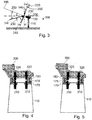
- FIG. 4 and 5 Two different angular positions of the yaw bearings 170 and 180 of the embodiment shown in Fig. 1 are illustrated in Figs. 4 and 5 .
- the nacelle and a shaft to which the hub of the wind energy system is mounted have been omitted from Figs. 4 and 5 , which can be seen as sectional views of the wind energy system shown in Fig. 1 and the tilt adjustment system shown in Fig. 2 .
- a bed plate 300 is arranged on top of the second or upper yaw bearing 180. Further, two bearing drives 310 for the lower first bearing 170 and two upper bearing drives 320 for the upper second bearing 180 are shown. The bearing drives 310, 320 are used to adjust the angular positions of the bearings 170 and 180. By adjusting the positions of the bearings 170 and 180, the yaw angle 265 and the tilt angle 240 of the tilt adjustment system can be altered.
- Typical embodiments use two bearing drives per bearing. Other typical embodiments described herein use four or only one bearing drive per bearing. More bearing drives can provide a more powerful positioning of the bearings. Fewer bearing drives or only one bearing drive provide less energy consumption.
- Embodiments described herein typically use a bed plate. Further wind energy systems according to embodiments described herein use a space frame or other frames as the main frame.
- Figs. 6 to 9 show gooseneck-type wind energy systems 100 according to embodiments described herein.
- the gooseneck-type wind energy systems 100 include a gooseneck 400 to which a first bearing 170 is mounted.
- an adapter 175 is mounted to the first bearing 170.
- the adapter 175 supports a gearbox 410 to which a generator 420 is mounted.
- the gearbox 410 is attached to the wall of the adapter 175 by flexible mounts 430.
- a second bearing 180 is mounted to the adapter 175.
- an additional bearing 440 is mounted to the adapter 175, wherein the second bearing 180 and the additional bearing 440 support a shaft 450.
- the hub 130 is mounted to the shaft 450 (not shown in Figs. 6 and 7 ). Again, the shaft 450 and the hub are rotatable about a rotation axis 190.
- the adapter 175 is tapered, such that the axes of rotation of the bearings 170 and 180 are inclined.
- a first bearing is mounted to a gooseneck-type nacelle, wherein a tapered adapter is mounted to the first bearing.
- the gearbox On the inner side of the walls of the adapter, the gearbox is mounted by simple flexible mounts.
- the gearbox is mounted by struts in other embodiments described herein. It will be noted that the struts or the flexible mounts are subjected to torque forces of the shaft. By rotating the first bearing, the tilt angle of the shaft can be adjusted without influencing the load on the flexible mounts.
- the second bearing is used as a main bearing for the shaft.
- Typical gooseneck-type embodiments include a yaw bearing below the gooseneck to alter the yaw angle. The yaw bearing of gooseneck-type embodiments is additional to the first and the second bearing.
- the gearbox is mounted to the gooseneck, wherein a flexible joint is connected to the shaft.
- a gearbox input shaft is connected to the flexible joint.
- FIG. 7 another position of the wind energy system of Fig. 6 is shown, wherein the first bearing 170 is turned about 180° such that the rotation axis 190 now has a tilt angle which is different in comparison to its initial tilt angle. Additionally, intermediate positions of the first bearing 170 can be used for adjustment of the tilt angle. Turning of the first bearing 170 could be used to adjust the tilt angle to actual wind inflow angles, which are not stable over time.
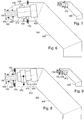
- Figs. 8 and 9 Another arrangement, according to embodiments described herein, is shown in Figs. 8 and 9 .
- the gearbox is typically mounted to the gooseneck via adjustable supports; the adjustable supports are hydraulic cylinders 470 in Fig. 8 .
- the gearbox 410 changes its vertical position. Since the gearbox 410 has to keep its angular position relative to the rotation axis of the hub, however, the hydraulic cylinders 470 are needed to keep this angular position.
- the hydraulic cylinders 470 When turning the first bearing 170, the hydraulic cylinders 470 have to be actuated to adjust the position of the gearbox 410.
- Figs. 8 and 9 show different positions of the first bearing 170 resulting in different tilt angles of the rotation axis 190 and in different positions of the gearbox 410.
- hydraulic cylinders are used as torque arms.
- electric motors are used to alter the vertical position of the gearbox.
- the mechanism for tilting the tilt axis could also be a flexible joint that allows some angular displacement about the tilt axis.
- Such flexible joints can be driven by hydraulics or by electricity.
- the torque arms are of a linkage type. Hydraulic cylinders perform well, have low energy consumption, and do not need much space.
- the torque arms 470 of Figs. 8 and 9 are shown in a schematic sectional view. Furthermore, the gearbox 410 is shown in a sectional view. The gearbox 410 is mounted to the two torque arms 470.
- the torque arms 470 are hydraulic cylinders, which are connected by a pressure equalizing line 480.
- the pressure equalizing line 480 allows limited rotation of the gearbox 410. This reduces forces to the walls of the gooseneck 400 to which the torque arms 470 are mounted.
- the torque arms are hydraulic cylinders connected by a pressure equalizing line. This setup provides a reduction of maximum forces to the supporting walls.
- springs are used as torque arms. Springs do not need maintenance and also reduce maximum forces.
- proper placement of the second bearing and the gearbox supports may make the need for adjustment of the length of the supports obsolete.
- the air speed indicator and the wind direction indicator are used to determine a set tilt angle and a set yaw angle.
- the turbine anemometry, or a combination of other sensors may serve to determine the upflow angle under the actual conditions.
- the set tilt angle is calculated according to the measured air speed value by use of a controller.
- typical site conditions can be considered to estimate an upflow angle of the wind.
- the site conditions can be stored in a table giving different upflow angles for different wind directions and different air speed values.
- a check is made to determine whether the calculated set tilt angle is smaller than a maximum tilt angle calculated depending on the air speed.
- the maximum tilt angle depends on the air speed. Additionally, the measured wind direction value (measured by the wind direction indicator) is considered to determine a set yaw angle.
- Fig. 11 shows which tilt angles Theta ⁇ (reference number 240 in other figures described herein) are allowed depending on the wind speed V_wind 121. Allowed tilt angles are above the curved line 122 shown in Fig. 11 .
- the expressions "increase”, “higher”, or other comparable expressions in conjunction with the tilt angle do not necessarily mean a numerical reduction or a numerical increase of the tilt angle.
- an alteration of the tilt angle to positions with the hub pointing slightly upwards is also included in the expression “increasing the tilt angle.”
- One aspect is the provision of sufficient clearance between the tower and the rotor blades.
- the controller After determining the set yaw angle and the set tilt angle, the controller actuates the first and the second bearing to position the nacelle in the optimal direction for the operation of the wind turbine. This is done by turning at least one of the first bearing and the second bearing, such that the tapered adapter is set in the correct angular position.
- additional embodiments according to Figs. 6 to 9 can also be positioned using the controller. It will be understood, however, that with these embodiments, a tilt angle can be altered directly (without affecting of the yaw angle) by simply turning the first bearing.
- Fig. 12 is a schematic view of a tilt adjustment system of a wind energy system according to embodiments described herein.
- the tilt adjustment system shown in Fig. 12 includes a first bearing or lower yaw bearing 170.
- the tilt adjustment system further includes an adapter 175 being arranged on top of the lower yaw bearing 170.
- the adapter 175 is also referred to as a first tapered adapter 175.
- a middle yaw bearing 500 is arranged on top of the first tapered adapter 175 with a second tapered adapter 510 being arranged thereon.
- an upper yaw bearing 180 is arranged, such that a stack of bearings and tapered adapters with an alternating order is provided.
- Wind energy systems according to embodiments described herein having three bearings and two adapters in a stacked order provide the possibility of adjusting the yaw angle, the roll angle, and the tilt angle of the nacelle independently of each other.
- Further typical embodiments include combinations of bearings being inclined to each other with tapered adapters between the bearings to make an adjustment of the tilt angle possible.
- the bearings and the adapters can be arranged between the nacelle and the tower or between the nacelle and the shaft.
- a combination of an inclined bearing under the nacelle and a further vertical bearing with an adapter supporting the shaft is also possible.
- Figs. 13 and 14 Two further arrangements, which are not part of the invention, according to embodiments described herein are shown in Figs. 13 and 14 . Both embodiments are part of a king-pin turbine, wherein the rotor and a portion of the drive train rotates about the king-pin.
- a king-pin is typically a movable connection of two parts.
- the king-pin is a pin on which a generator of a wind energy system may be mounted.
- Fig. 13 a tilt adjustment system according to embodiments described herein is shown.
- the shown embodiment uses a king-pin 550 on which a hollow shaft 450 is mounted by second bearings 180. In connection with Figs.
- the phrase "shaft” is used in the meaning of driveshaft, which may be hollow.
- the shaft 450 and a hub 130 rotate about a rotation axis 190, which is parallel to the longitudinal axis of the king-pin 550.
- a tapered adapter 175 is formed integrally with the king-pin 550, wherein the tapered adapter 175, together with the integral formed king-pin 550, is rotatable about a horizontal axis.
- the tapered adapter 175 can also be referred to as an inclined adapter being integral with the king pin 550.
- An inclined axle is formed by the king-pin 550 together with the integral tapered adapter 175.
- the inclined axle is shown as rotation axis 190.
- the axis of the axle is non-perpendicular to an active tilt bearing, namely a first bearing 170.
- the first bearing 170 is used to rotate the tapered adapter 175 and the integral formed king-pin about the horizontal axis. Due to the tapered form of the integral formed tapered adapter 175 and king-pin 550, the axis of rotation 190 of the hub 130 is tilted by rotation of the first bearing 170. Therefore, in the embodiment shown in Fig. 13 , the first bearing can be construed as a tilt bearing.
- the second bearings 180 can be referred to as shaft bearings. It should be mentioned that the embodiment shown in Fig. 13 uses a hydrostatic drive with pumps 560 for power transmission from the shaft 450 to a remote generator.
- Fig. 14 another tilt adjustment system according to embodiments described herein is shown.
- the shown embodiment uses a king-pin 550 on which a hollow shaft 450 is mounted by second bearings 180. Therefore, the embodiment shown in Fig. 14 has similarities to the one shown in Fig. 13 . However, the embodiment shown in Fig. 14 is adapted for use together with a direct drive generator.
- the rotor can be mounted to the shaft 450, wherein a stator would be situated concentrically to the shaft 450.
- wind energy systems and tilt adjustment systems with a king-pin arrangement can be used to build compact wind energy systems.
- the hydrostatic drive or the direct drive also provides for a compact system.
- the gooseneck-type configuration can be used to enhance the clearance between the tower and the blades, thus providing more flexibility in choosing the tilt angle.
- the tilt angle can be altered with different embodiments described herein.
- Typical power transmissions use hydrostatic, hydrodynamic, gearbox, or direct drives, wherein other drive systems can also be combined with embodiments described herein.
Landscapes
- Engineering & Computer Science (AREA)
- Life Sciences & Earth Sciences (AREA)
- Sustainable Development (AREA)
- Sustainable Energy (AREA)
- Chemical & Material Sciences (AREA)
- Combustion & Propulsion (AREA)
- Mechanical Engineering (AREA)
- General Engineering & Computer Science (AREA)
- Wind Motors (AREA)
Applications Claiming Priority (1)
| Application Number | Priority Date | Filing Date | Title |
|---|---|---|---|
| US12/765,001 US8277184B2 (en) | 2010-04-22 | 2010-04-22 | Tilt adjustment system |
Publications (3)
| Publication Number | Publication Date |
|---|---|
| EP2381100A2 EP2381100A2 (en) | 2011-10-26 |
| EP2381100A3 EP2381100A3 (en) | 2014-05-07 |
| EP2381100B1 true EP2381100B1 (en) | 2017-06-14 |
Family
ID=44123150
Family Applications (1)
| Application Number | Title | Priority Date | Filing Date |
|---|---|---|---|
| EP11163282.4A Active EP2381100B1 (en) | 2010-04-22 | 2011-04-20 | Tilt adjustment system |
Country Status (8)
| Country | Link |
|---|---|
| US (1) | US8277184B2 (enExample) |
| EP (1) | EP2381100B1 (enExample) |
| JP (1) | JP2011226486A (enExample) |
| KR (1) | KR20110118096A (enExample) |
| CN (1) | CN102235296B (enExample) |
| AU (1) | AU2011201775B2 (enExample) |
| CA (1) | CA2737441C (enExample) |
| DK (1) | DK2381100T3 (enExample) |
Families Citing this family (33)
| Publication number | Priority date | Publication date | Assignee | Title |
|---|---|---|---|---|
| EP2458199B1 (en) * | 2009-06-30 | 2016-04-13 | Tempero 2000 S.L. | Wind turbine with compensated motor torque |
| USD698726S1 (en) * | 2011-03-30 | 2014-02-04 | Vestas Wind Systems A/S | Wind turbine structure |
| FR2984968B1 (fr) * | 2011-12-23 | 2014-05-16 | IFP Energies Nouvelles | Dispositif de controle de la position du plan des pales d'eoliennes |
| WO2013109611A1 (en) * | 2012-01-17 | 2013-07-25 | United Technologies Corporation | Generator with stator supported on rotor |
| WO2014015882A1 (en) * | 2012-07-26 | 2014-01-30 | Vestas Wind Systems A/S | Tilting wind turbine |
| JP2015522757A (ja) | 2012-07-26 | 2015-08-06 | エムエイチアイ ヴェスタス オフショア ウィンド エー/エス | 風力タービン傾斜最適化及び制御 |
| KR101400177B1 (ko) | 2012-09-07 | 2014-06-27 | 삼성중공업 주식회사 | 풍력발전기 및 풍력발전기의 운용방법 |
| JP2014101756A (ja) * | 2012-11-16 | 2014-06-05 | Matsumoto Kenzai:Kk | 風力発電装置 |
| EP2784304B1 (en) * | 2013-03-27 | 2016-08-31 | Alstom Renovables España, S.L. | Method of operating a wind turbine |
| EP3653357A1 (en) | 2013-12-13 | 2020-05-20 | Covco (H.K.) Limited | Ambidextrous fish scale-textured glove |
| US9730477B2 (en) | 2013-12-13 | 2017-08-15 | Covco Ltd. | Ambidextrous fish scale-textured glove |
| US11241051B2 (en) | 2014-07-08 | 2022-02-08 | Covco (H.K.) Limited | Ambidextrous fish scale-textured glove |
| DE202013012402U1 (de) | 2013-12-13 | 2016-10-26 | John Joseph FURLONG | Beidhändiger Handschuh mit Fischschuppentextur |
| JP5984792B2 (ja) * | 2013-12-27 | 2016-09-06 | 三菱重工業株式会社 | 風力発電装置 |
| US8950150B1 (en) | 2014-05-21 | 2015-02-10 | Ray Pecor | Apparatus for maintaining optimum orientation of tower mounted devices |
| BR112016028631A2 (pt) * | 2014-06-27 | 2017-08-22 | Nabrawind Sl | dispositivo de alteração do ângulo de inclinação no eixo horizontal de turbinas eólicas |
| WO2016024028A1 (es) * | 2014-08-13 | 2016-02-18 | Nabrawind Sl | Integración de un generador en el sistema de transmisión de un aerogenerador |
| WO2016155740A1 (en) * | 2015-03-30 | 2016-10-06 | Vestas Wind Systems A/S | A wind turbine comprising two or more rotors |
| WO2016155741A1 (en) * | 2015-03-30 | 2016-10-06 | Vestas Wind Systems A/S | A wind turbine with a rotor comprising a hollow king pin |
| ES2552363B1 (es) * | 2015-10-22 | 2016-05-23 | Dreiventum S L U | Torre eólica multi-plataforma |
| US9982659B1 (en) | 2017-02-03 | 2018-05-29 | General Electric Company | Methods for refurbishing wind turbines |
| US11009006B2 (en) * | 2018-03-19 | 2021-05-18 | David Favela | Vertical-axis wind turbine |
| AT521071B1 (de) * | 2018-03-23 | 2019-12-15 | Miba Gleitlager Austria Gmbh | Windkraftanlagengetriebe und Verfahren zum Herstellen eines Windkraftanlagengetriebes |
| US10570889B2 (en) | 2018-04-23 | 2020-02-25 | General Electric Company | Adaptor for wind turbine refurbishment and associated methods |
| CN109113932A (zh) * | 2018-08-02 | 2019-01-01 | 深圳市福瑞禧科技发展有限公司 | 一种新能源风力发电装置及其发电系统 |
| US11231017B2 (en) | 2019-03-29 | 2022-01-25 | General Electric Company | System and method for the service and exchange of a yaw bearing for a machine head of a wind turbine |
| US20220372954A1 (en) * | 2020-01-28 | 2022-11-24 | Mohan Rajkumar DEWAN | Solar panelled windmill assembly |
| CN114109719B (zh) * | 2021-11-05 | 2024-01-05 | 广东海洋大学 | 一种可根据风向调节改变迎风角度的风能发电装置 |
| CN114109743B (zh) * | 2021-11-19 | 2024-08-20 | 西安热工研究院有限公司 | 一种风力发电塔筒倾斜度监测装置及方法 |
| KR102762037B1 (ko) * | 2021-12-13 | 2025-02-04 | 이모션웨이브 주식회사 | 인공지능 드럼 연주 장치 |
| USD1042341S1 (en) * | 2021-12-21 | 2024-09-17 | Kodair Wind Designs Limited | Wind turbine |
| CN115387971B (zh) * | 2022-08-15 | 2025-04-25 | 太原重工股份有限公司 | 风力发电机组机舱 |
| US12515790B2 (en) * | 2023-06-16 | 2026-01-06 | Maglev Aero Inc. | Systems and methods for vertical takeoff and landing vehicle with stator stabilization |
Family Cites Families (18)
| Publication number | Priority date | Publication date | Assignee | Title |
|---|---|---|---|---|
| US4045147A (en) * | 1976-05-10 | 1977-08-30 | Ssp Agricultural Equipment, Inc. | Tiltable wind machine for use on variable terrain |
| US5354175A (en) * | 1992-03-16 | 1994-10-11 | Northern Power Systems, Inc. | Wind turbine rotor hub and teeter joint |
| US6327957B1 (en) * | 1998-01-09 | 2001-12-11 | Wind Eagle Joint Venture | Wind-driven electric generator apparatus of the downwind type with flexible changeable-pitch blades |
| ES2179785B1 (es) * | 2001-06-12 | 2006-10-16 | Ivan Lahuerta Antoune | Turbina eolica autotimonante. |
| JP2003035249A (ja) * | 2001-07-23 | 2003-02-07 | Fuji Heavy Ind Ltd | 水平軸風車のティルト角制御方法及びその装置 |
| DE10140793A1 (de) | 2001-08-20 | 2003-03-06 | Gen Electric | Einrichtung zum Verstellen des Rotorblattes eines Rotors einer Windkraftanlage |
| US20040076518A1 (en) * | 2002-10-17 | 2004-04-22 | Drake Devon Glen | Tilt stabilized / ballast controlled wind turbine |
| CN100350154C (zh) | 2003-09-03 | 2007-11-21 | 通用电气公司 | 风力涡轮机的冗余叶片节距控制系统和控制风力涡轮机的方法 |
| US7075192B2 (en) * | 2004-04-19 | 2006-07-11 | Northern Power Systems, Inc. | Direct drive wind turbine |
| DE102004027992B4 (de) | 2004-06-09 | 2011-06-16 | Kenersys Gmbh | Windenergieanlage mit einem Azimutsystem |
| ITRE20040015U1 (it) * | 2004-08-02 | 2004-11-02 | Annovi Reverberi Spa | Corpo per pompa a pistoni tuffanti |
| EP1647708A1 (en) | 2004-10-14 | 2006-04-19 | General Electric Company | Pitch drive system for a wind turbine |
| JP2006200400A (ja) | 2005-01-19 | 2006-08-03 | Fuji Heavy Ind Ltd | 水平軸風車 |
| JP4890013B2 (ja) * | 2005-12-01 | 2012-03-07 | トヨタ自動車株式会社 | ストラット式サスペンション |
| DE102006031174B3 (de) | 2006-07-03 | 2007-10-25 | Repower Systems Ag | Rotornabe einer Windenergieanlage |
| CN101600879B (zh) | 2006-11-27 | 2012-07-18 | Lm玻璃纤维有限公司 | 风力发电站上的叶片的桨距 |
| DE102007019513B4 (de) * | 2007-04-25 | 2012-03-15 | Aerodyn Engineering Gmbh | Windenergieanlage |
| JP2010168937A (ja) * | 2009-01-21 | 2010-08-05 | Mitsubishi Heavy Ind Ltd | アップウインド型風力発電設備 |
-
2010
- 2010-04-22 US US12/765,001 patent/US8277184B2/en active Active
-
2011
- 2011-04-14 CA CA2737441A patent/CA2737441C/en not_active Expired - Fee Related
- 2011-04-19 JP JP2011092939A patent/JP2011226486A/ja active Pending
- 2011-04-19 AU AU2011201775A patent/AU2011201775B2/en not_active Ceased
- 2011-04-20 EP EP11163282.4A patent/EP2381100B1/en active Active
- 2011-04-20 DK DK11163282.4T patent/DK2381100T3/en active
- 2011-04-21 KR KR1020110037333A patent/KR20110118096A/ko not_active Withdrawn
- 2011-04-21 CN CN201110112987.2A patent/CN102235296B/zh not_active Expired - Fee Related
Non-Patent Citations (1)
| Title |
|---|
| None * |
Also Published As
| Publication number | Publication date |
|---|---|
| US20110262272A1 (en) | 2011-10-27 |
| DK2381100T3 (en) | 2017-08-28 |
| CN102235296B (zh) | 2014-09-24 |
| KR20110118096A (ko) | 2011-10-28 |
| JP2011226486A (ja) | 2011-11-10 |
| CA2737441C (en) | 2014-05-20 |
| EP2381100A2 (en) | 2011-10-26 |
| AU2011201775A1 (en) | 2011-11-10 |
| AU2011201775B2 (en) | 2013-09-05 |
| CA2737441A1 (en) | 2011-10-22 |
| EP2381100A3 (en) | 2014-05-07 |
| CN102235296A (zh) | 2011-11-09 |
| US8277184B2 (en) | 2012-10-02 |
Similar Documents
| Publication | Publication Date | Title |
|---|---|---|
| EP2381100B1 (en) | Tilt adjustment system | |
| US5584655A (en) | Rotor device and control for wind turbine | |
| US8021101B2 (en) | Wind turbine and method of assembling the same | |
| EP2992208B1 (en) | System and method for controlling offshore floating wind turbine platforms | |
| US9041237B2 (en) | Wind turbine drive train and wind turbine | |
| US20100054939A1 (en) | Method and apparatus for adjusting a yaw angle of a wind turbine | |
| EP2383466A2 (en) | Wind turbine with integrated design and controlling method | |
| CN107041149B (zh) | 竖向风电设备以及操作这种设备的方法 | |
| WO1996020343A9 (en) | Rotor device and control for wind turbine | |
| CN101761449A (zh) | 垂直轴风力发电系统及其风叶角度自动调节装置 | |
| KR20130097171A (ko) | 디렉트 드라이브 윈드 터빈 및 에어 갭을 제어하기 위한 방법 | |
| US8753085B2 (en) | Device for changing a pitch of a blade of an impeller/propeller and a fan comprising the device | |
| WO2011105970A2 (en) | Wind generator with vertical rotation axis, in particular for mobile applications | |
| JP7600100B2 (ja) | ローター軸受ハウジング、及びローター軸受ハウジングを備える風力タービン | |
| KR102275378B1 (ko) | 멀티형 풍력 발전기 및 멀티형 풍력 발전기의 요잉 방법 | |
| KR102071323B1 (ko) | 멀티형 풍력 발전기 및 이의 제어 방법 | |
| CN102359435B (zh) | 垂直轴风力发电系统 | |
| US9938959B2 (en) | Hub and bearing system and a turbine comprising the hub and bearing system | |
| CN102926931A (zh) | 用于风力涡轮机的浆距角的调节系统 | |
| CN102338036A (zh) | 垂直轴风力发电系统及其风叶角度自动调节装置 | |
| EP2981713B1 (en) | A hub and bearing system and a turbine comprising the hub and bearing system | |
| CN102364092A (zh) | 垂直轴风力发电系统及其风叶角度自动调节装置 | |
| CN121894173A (zh) | 一种飞行器燃油系统多自由度模拟实验平台 |
Legal Events
| Date | Code | Title | Description |
|---|---|---|---|
| AK | Designated contracting states |
Kind code of ref document: A2 Designated state(s): AL AT BE BG CH CY CZ DE DK EE ES FI FR GB GR HR HU IE IS IT LI LT LU LV MC MK MT NL NO PL PT RO RS SE SI SK SM TR |
|
| AX | Request for extension of the european patent |
Extension state: BA ME |
|
| PUAI | Public reference made under article 153(3) epc to a published international application that has entered the european phase |
Free format text: ORIGINAL CODE: 0009012 |
|
| PUAL | Search report despatched |
Free format text: ORIGINAL CODE: 0009013 |
|
| AK | Designated contracting states |
Kind code of ref document: A3 Designated state(s): AL AT BE BG CH CY CZ DE DK EE ES FI FR GB GR HR HU IE IS IT LI LT LU LV MC MK MT NL NO PL PT RO RS SE SI SK SM TR |
|
| AX | Request for extension of the european patent |
Extension state: BA ME |
|
| RIC1 | Information provided on ipc code assigned before grant |
Ipc: F03D 11/00 20060101AFI20140401BHEP Ipc: F03D 7/02 20060101ALI20140401BHEP |
|
| 17P | Request for examination filed |
Effective date: 20141107 |
|
| RBV | Designated contracting states (corrected) |
Designated state(s): AL AT BE BG CH CY CZ DE DK EE ES FI FR GB GR HR HU IE IS IT LI LT LU LV MC MK MT NL NO PL PT RO RS SE SI SK SM TR |
|
| 17Q | First examination report despatched |
Effective date: 20160510 |
|
| REG | Reference to a national code |
Ref country code: DE Ref legal event code: R079 Ref document number: 602011038646 Country of ref document: DE Free format text: PREVIOUS MAIN CLASS: F03D0011000000 Ipc: F03D0080700000 |
|
| GRAP | Despatch of communication of intention to grant a patent |
Free format text: ORIGINAL CODE: EPIDOSNIGR1 |
|
| RIC1 | Information provided on ipc code assigned before grant |
Ipc: F03D 7/02 20060101ALI20170125BHEP Ipc: F03D 80/70 20160101AFI20170125BHEP |
|
| INTG | Intention to grant announced |
Effective date: 20170210 |
|
| GRAS | Grant fee paid |
Free format text: ORIGINAL CODE: EPIDOSNIGR3 |
|
| GRAA | (expected) grant |
Free format text: ORIGINAL CODE: 0009210 |
|
| AK | Designated contracting states |
Kind code of ref document: B1 Designated state(s): AL AT BE BG CH CY CZ DE DK EE ES FI FR GB GR HR HU IE IS IT LI LT LU LV MC MK MT NL NO PL PT RO RS SE SI SK SM TR |
|
| REG | Reference to a national code |
Ref country code: GB Ref legal event code: FG4D |
|
| REG | Reference to a national code |
Ref country code: CH Ref legal event code: EP Ref country code: AT Ref legal event code: REF Ref document number: 901252 Country of ref document: AT Kind code of ref document: T Effective date: 20170615 |
|
| REG | Reference to a national code |
Ref country code: IE Ref legal event code: FG4D |
|
| REG | Reference to a national code |
Ref country code: DE Ref legal event code: R096 Ref document number: 602011038646 Country of ref document: DE |
|
| REG | Reference to a national code |
Ref country code: DK Ref legal event code: T3 Effective date: 20170822 |
|
| REG | Reference to a national code |
Ref country code: NL Ref legal event code: MP Effective date: 20170614 |
|
| REG | Reference to a national code |
Ref country code: LT Ref legal event code: MG4D |
|
| PG25 | Lapsed in a contracting state [announced via postgrant information from national office to epo] |
Ref country code: HR Free format text: LAPSE BECAUSE OF FAILURE TO SUBMIT A TRANSLATION OF THE DESCRIPTION OR TO PAY THE FEE WITHIN THE PRESCRIBED TIME-LIMIT Effective date: 20170614 Ref country code: NO Free format text: LAPSE BECAUSE OF FAILURE TO SUBMIT A TRANSLATION OF THE DESCRIPTION OR TO PAY THE FEE WITHIN THE PRESCRIBED TIME-LIMIT Effective date: 20170914 Ref country code: LT Free format text: LAPSE BECAUSE OF FAILURE TO SUBMIT A TRANSLATION OF THE DESCRIPTION OR TO PAY THE FEE WITHIN THE PRESCRIBED TIME-LIMIT Effective date: 20170614 Ref country code: ES Free format text: LAPSE BECAUSE OF FAILURE TO SUBMIT A TRANSLATION OF THE DESCRIPTION OR TO PAY THE FEE WITHIN THE PRESCRIBED TIME-LIMIT Effective date: 20170614 Ref country code: GR Free format text: LAPSE BECAUSE OF FAILURE TO SUBMIT A TRANSLATION OF THE DESCRIPTION OR TO PAY THE FEE WITHIN THE PRESCRIBED TIME-LIMIT Effective date: 20170915 Ref country code: FI Free format text: LAPSE BECAUSE OF FAILURE TO SUBMIT A TRANSLATION OF THE DESCRIPTION OR TO PAY THE FEE WITHIN THE PRESCRIBED TIME-LIMIT Effective date: 20170614 |
|
| REG | Reference to a national code |
Ref country code: AT Ref legal event code: MK05 Ref document number: 901252 Country of ref document: AT Kind code of ref document: T Effective date: 20170614 |
|
| PG25 | Lapsed in a contracting state [announced via postgrant information from national office to epo] |
Ref country code: BG Free format text: LAPSE BECAUSE OF FAILURE TO SUBMIT A TRANSLATION OF THE DESCRIPTION OR TO PAY THE FEE WITHIN THE PRESCRIBED TIME-LIMIT Effective date: 20170914 Ref country code: LV Free format text: LAPSE BECAUSE OF FAILURE TO SUBMIT A TRANSLATION OF THE DESCRIPTION OR TO PAY THE FEE WITHIN THE PRESCRIBED TIME-LIMIT Effective date: 20170614 Ref country code: NL Free format text: LAPSE BECAUSE OF FAILURE TO SUBMIT A TRANSLATION OF THE DESCRIPTION OR TO PAY THE FEE WITHIN THE PRESCRIBED TIME-LIMIT Effective date: 20170614 Ref country code: RS Free format text: LAPSE BECAUSE OF FAILURE TO SUBMIT A TRANSLATION OF THE DESCRIPTION OR TO PAY THE FEE WITHIN THE PRESCRIBED TIME-LIMIT Effective date: 20170614 Ref country code: SE Free format text: LAPSE BECAUSE OF FAILURE TO SUBMIT A TRANSLATION OF THE DESCRIPTION OR TO PAY THE FEE WITHIN THE PRESCRIBED TIME-LIMIT Effective date: 20170614 |
|
| PG25 | Lapsed in a contracting state [announced via postgrant information from national office to epo] |
Ref country code: EE Free format text: LAPSE BECAUSE OF FAILURE TO SUBMIT A TRANSLATION OF THE DESCRIPTION OR TO PAY THE FEE WITHIN THE PRESCRIBED TIME-LIMIT Effective date: 20170614 Ref country code: CZ Free format text: LAPSE BECAUSE OF FAILURE TO SUBMIT A TRANSLATION OF THE DESCRIPTION OR TO PAY THE FEE WITHIN THE PRESCRIBED TIME-LIMIT Effective date: 20170614 Ref country code: RO Free format text: LAPSE BECAUSE OF FAILURE TO SUBMIT A TRANSLATION OF THE DESCRIPTION OR TO PAY THE FEE WITHIN THE PRESCRIBED TIME-LIMIT Effective date: 20170614 Ref country code: AT Free format text: LAPSE BECAUSE OF FAILURE TO SUBMIT A TRANSLATION OF THE DESCRIPTION OR TO PAY THE FEE WITHIN THE PRESCRIBED TIME-LIMIT Effective date: 20170614 Ref country code: SK Free format text: LAPSE BECAUSE OF FAILURE TO SUBMIT A TRANSLATION OF THE DESCRIPTION OR TO PAY THE FEE WITHIN THE PRESCRIBED TIME-LIMIT Effective date: 20170614 |
|
| PG25 | Lapsed in a contracting state [announced via postgrant information from national office to epo] |
Ref country code: PL Free format text: LAPSE BECAUSE OF FAILURE TO SUBMIT A TRANSLATION OF THE DESCRIPTION OR TO PAY THE FEE WITHIN THE PRESCRIBED TIME-LIMIT Effective date: 20170614 Ref country code: SM Free format text: LAPSE BECAUSE OF FAILURE TO SUBMIT A TRANSLATION OF THE DESCRIPTION OR TO PAY THE FEE WITHIN THE PRESCRIBED TIME-LIMIT Effective date: 20170614 Ref country code: IT Free format text: LAPSE BECAUSE OF FAILURE TO SUBMIT A TRANSLATION OF THE DESCRIPTION OR TO PAY THE FEE WITHIN THE PRESCRIBED TIME-LIMIT Effective date: 20170614 Ref country code: IS Free format text: LAPSE BECAUSE OF FAILURE TO SUBMIT A TRANSLATION OF THE DESCRIPTION OR TO PAY THE FEE WITHIN THE PRESCRIBED TIME-LIMIT Effective date: 20171014 |
|
| REG | Reference to a national code |
Ref country code: DE Ref legal event code: R097 Ref document number: 602011038646 Country of ref document: DE |
|
| PLBE | No opposition filed within time limit |
Free format text: ORIGINAL CODE: 0009261 |
|
| STAA | Information on the status of an ep patent application or granted ep patent |
Free format text: STATUS: NO OPPOSITION FILED WITHIN TIME LIMIT |
|
| 26N | No opposition filed |
Effective date: 20180315 |
|
| PG25 | Lapsed in a contracting state [announced via postgrant information from national office to epo] |
Ref country code: SI Free format text: LAPSE BECAUSE OF FAILURE TO SUBMIT A TRANSLATION OF THE DESCRIPTION OR TO PAY THE FEE WITHIN THE PRESCRIBED TIME-LIMIT Effective date: 20170614 |
|
| PG25 | Lapsed in a contracting state [announced via postgrant information from national office to epo] |
Ref country code: MC Free format text: LAPSE BECAUSE OF FAILURE TO SUBMIT A TRANSLATION OF THE DESCRIPTION OR TO PAY THE FEE WITHIN THE PRESCRIBED TIME-LIMIT Effective date: 20170614 |
|
| REG | Reference to a national code |
Ref country code: CH Ref legal event code: PL |
|
| REG | Reference to a national code |
Ref country code: BE Ref legal event code: MM Effective date: 20180430 |
|
| GBPC | Gb: european patent ceased through non-payment of renewal fee |
Effective date: 20180420 |
|
| REG | Reference to a national code |
Ref country code: IE Ref legal event code: MM4A |
|
| PG25 | Lapsed in a contracting state [announced via postgrant information from national office to epo] |
Ref country code: LU Free format text: LAPSE BECAUSE OF NON-PAYMENT OF DUE FEES Effective date: 20180420 |
|
| PG25 | Lapsed in a contracting state [announced via postgrant information from national office to epo] |
Ref country code: GB Free format text: LAPSE BECAUSE OF NON-PAYMENT OF DUE FEES Effective date: 20180420 Ref country code: CH Free format text: LAPSE BECAUSE OF NON-PAYMENT OF DUE FEES Effective date: 20180430 Ref country code: BE Free format text: LAPSE BECAUSE OF NON-PAYMENT OF DUE FEES Effective date: 20180430 Ref country code: LI Free format text: LAPSE BECAUSE OF NON-PAYMENT OF DUE FEES Effective date: 20180430 |
|
| PG25 | Lapsed in a contracting state [announced via postgrant information from national office to epo] |
Ref country code: IE Free format text: LAPSE BECAUSE OF NON-PAYMENT OF DUE FEES Effective date: 20180420 Ref country code: FR Free format text: LAPSE BECAUSE OF NON-PAYMENT OF DUE FEES Effective date: 20180430 |
|
| PG25 | Lapsed in a contracting state [announced via postgrant information from national office to epo] |
Ref country code: MT Free format text: LAPSE BECAUSE OF NON-PAYMENT OF DUE FEES Effective date: 20180420 |
|
| PG25 | Lapsed in a contracting state [announced via postgrant information from national office to epo] |
Ref country code: TR Free format text: LAPSE BECAUSE OF FAILURE TO SUBMIT A TRANSLATION OF THE DESCRIPTION OR TO PAY THE FEE WITHIN THE PRESCRIBED TIME-LIMIT Effective date: 20170614 |
|
| PG25 | Lapsed in a contracting state [announced via postgrant information from national office to epo] |
Ref country code: PT Free format text: LAPSE BECAUSE OF FAILURE TO SUBMIT A TRANSLATION OF THE DESCRIPTION OR TO PAY THE FEE WITHIN THE PRESCRIBED TIME-LIMIT Effective date: 20170614 Ref country code: HU Free format text: LAPSE BECAUSE OF FAILURE TO SUBMIT A TRANSLATION OF THE DESCRIPTION OR TO PAY THE FEE WITHIN THE PRESCRIBED TIME-LIMIT; INVALID AB INITIO Effective date: 20110420 |
|
| PG25 | Lapsed in a contracting state [announced via postgrant information from national office to epo] |
Ref country code: CY Free format text: LAPSE BECAUSE OF FAILURE TO SUBMIT A TRANSLATION OF THE DESCRIPTION OR TO PAY THE FEE WITHIN THE PRESCRIBED TIME-LIMIT Effective date: 20170614 Ref country code: MK Free format text: LAPSE BECAUSE OF NON-PAYMENT OF DUE FEES Effective date: 20170614 |
|
| PG25 | Lapsed in a contracting state [announced via postgrant information from national office to epo] |
Ref country code: AL Free format text: LAPSE BECAUSE OF FAILURE TO SUBMIT A TRANSLATION OF THE DESCRIPTION OR TO PAY THE FEE WITHIN THE PRESCRIBED TIME-LIMIT Effective date: 20170614 |
|
| P01 | Opt-out of the competence of the unified patent court (upc) registered |
Effective date: 20230530 |
|
| REG | Reference to a national code |
Ref country code: DE Ref legal event code: R081 Ref document number: 602011038646 Country of ref document: DE Owner name: GENERAL ELECTRIC RENOVABLES ESPANA, S.L., ES Free format text: FORMER OWNER: GENERAL ELECTRIC COMPANY, SCHENECTADY, NY, US |
|
| PGFP | Annual fee paid to national office [announced via postgrant information from national office to epo] |
Ref country code: DK Payment date: 20250319 Year of fee payment: 15 |
|
| PGFP | Annual fee paid to national office [announced via postgrant information from national office to epo] |
Ref country code: DE Payment date: 20250319 Year of fee payment: 15 |