EP2381053A2 - Schliesszylinder, insbesondere für Türschlösser von Kraftfahrzeugen - Google Patents
Schliesszylinder, insbesondere für Türschlösser von Kraftfahrzeugen Download PDFInfo
- Publication number
- EP2381053A2 EP2381053A2 EP11002563A EP11002563A EP2381053A2 EP 2381053 A2 EP2381053 A2 EP 2381053A2 EP 11002563 A EP11002563 A EP 11002563A EP 11002563 A EP11002563 A EP 11002563A EP 2381053 A2 EP2381053 A2 EP 2381053A2
- Authority
- EP
- European Patent Office
- Prior art keywords
- cylinder
- freewheel sleeve
- lock
- return spring
- sleeve
- Prior art date
- Legal status (The legal status is an assumption and is not a legal conclusion. Google has not performed a legal analysis and makes no representation as to the accuracy of the status listed.)
- Granted
Links
Images


Classifications
-
- E—FIXED CONSTRUCTIONS
- E05—LOCKS; KEYS; WINDOW OR DOOR FITTINGS; SAFES
- E05B—LOCKS; ACCESSORIES THEREFOR; HANDCUFFS
- E05B85/00—Details of vehicle locks not provided for in groups E05B77/00 - E05B83/00
- E05B85/06—Lock cylinder arrangements
-
- E—FIXED CONSTRUCTIONS
- E05—LOCKS; KEYS; WINDOW OR DOOR FITTINGS; SAFES
- E05B—LOCKS; ACCESSORIES THEREFOR; HANDCUFFS
- E05B17/00—Accessories in connection with locks
- E05B17/04—Devices for coupling the turning cylinder of a single or a double cylinder lock with the bolt operating member
- E05B17/044—Clutches, disengageable couplings
- E05B17/045—Clutches, disengageable couplings for keeping the rotor disconnected from the bolt actuating member, when being turned, e.g. forcefully, without the proper key
-
- E—FIXED CONSTRUCTIONS
- E05—LOCKS; KEYS; WINDOW OR DOOR FITTINGS; SAFES
- E05B—LOCKS; ACCESSORIES THEREFOR; HANDCUFFS
- E05B17/00—Accessories in connection with locks
- E05B17/04—Devices for coupling the turning cylinder of a single or a double cylinder lock with the bolt operating member
- E05B17/041—Coupling device with a shaft projecting axially rearwardly from the cylinder, e.g. affording a degree of universal motion to compensate for misalignment
Definitions
- the invention relates to a lock cylinder, in particular for door locks of motor vehicles, according to the preamble of claim 1.
- a lock cylinder of the generic type describes the EP 0 659 962 B1 , Background is a lock construction in which it is ensured by cooperating with the cylinder freewheel sleeve that a violent rotation of the cylinder without proper key does not damage the tumblers of the cylinder and possibly the lock cylinder is destroyed.
- a defined torque on the freewheel sleeve detent connection between freewheel sleeve and lock housing dissolves, at the same time the driving connection of the cylinder to the downstream lock, for example, a door lock or hood lock of motor vehicles, interrupted.
- the cylinder can rotate freely with the freewheel sleeve.
- a return spring is provided, which in normal operation of the cylinder via the corresponding key each resiliently returns to a starting position.
- the object of the invention is to propose a lock cylinder, especially for door locks of motor vehicles, which is structurally and functionally particularly favorable and also allows easy installation of the return spring in the lock cylinder.
- a lock cylinder in particular for door locks of motor vehicles, proposed with an inner, tumblers having cylinder or cylinder part, which cooperates with a cylinder, for example, telescopically enclosing freewheel sleeve, wherein the freewheel sleeve has the tumblers associated recesses and in an outer , Solid housing is rotatably mounted.
- a coupling device and a locking means is provided, which solve the locking connection between the housing and the freewheel sleeve at a defined torque on the freewheel sleeve and at the same time control a decoupling between the cylinder and a downstream lock, wherein a force acting on the cylinder return spring is provided.
- the return spring is functionally switched between the cylinder and the freewheel sleeve.
- the return spring is functionally behind the coupling point and in Abuse case (freewheel activated) is not moved
- the present proposal that turns in abuse case, the entire package of preferably freewheel spring, cylinder and return spring, ie that the return spring is thus rotated in the abuse case.
- the regular reset function remains ensured as long as the freewheel sleeve is latched to the fixed housing.
- the return spring which is preferably designed as a leg spring, can furthermore be arranged spatially within the freewheel sleeve and around a cylindrical extension of the cylinder. This results in a slimmer lock construction with return spring integrated between the cylinder and the freewheel sleeve.
- arms projecting radially from the return spring designed as a leg spring can be supported by circumferential slots in the freewheel sleeve on the freewheel sleeve and in circumferentially open recesses in a hub of the cylinder which is formed around the cylindrical projection and is partially open in the circumferential direction. This allows a manufacturing technology simple and very reliable position of the return spring within the freewheel sleeve.
- the arms of the return spring in the mounting direction facing oblique ramps are formed on the recesses of the hub.
- the return spring can be positioned substantially radially within an outer freewheeling spring designed as an annular spring, wherein the freewheeling spring is arranged around an annular collar of the fixed housing and acts on a coupling pin which extends radially from a defined torque on the freewheel sleeve and the latching connection between the housing and the freewheel sleeve dissolves.
- the stacking nesting of the two springs also allows a particularly short-built lock cylinder in the axial direction.
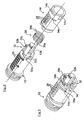
- a lock cylinder for door locks of motor vehicles that essentially consists of a rotationally symmetric cylinder 12, a cylinder 12 over almost its entire length enclosing freewheel sleeve 14 and an outer housing 16.
- the door lock 10 has to be described locking means in the form of a coupling pin 18 (FIG. Fig. 4 ) and a coupling device 20.
- a coupling pin 18 (FIG. Fig. 4 )
- a coupling device 20 To the coupling device 20 is connected as a driving connection with the door lock (not shown) of the motor vehicle, a gimbal hinged connecting rod 22 and an engaging directly into the mechanics of the door lock knob 24.
- lock cylinder 10 is described with the coupling device 20 only insofar as is necessary for the understanding of the present invention.
- the cylinder 12 (compare also FIGS. 2 and 3 ) is rotatably mounted in the freewheel sleeve 14 and has in a known manner a plurality of radially displaceable tumblers 26 which extend radially with the key removed and engage in corresponding recesses 28 of the freewheel sleeve 14.
- the cylinder 12 is held by means of a functionally and spatially between the here exemplified rear portion (extension 12b) of the cylinder 12 and the freewheel sleeve 14, designed as a leg spring return spring 30 with two radially projecting arms 30a, 30b in a defined rotational position relative to the freewheel sleeve 14 ,
- the arms 30a, 30b of the return spring 30 pass through two mutually offset circumferential slots 14a, 14b in the freewheel sleeve 14 and are within this on acting in the circumferential direction recesses 32a, 32b, which incorporated into a partially extending around the extension 12b hub 32 of the cylinder 12 are.
- the return spring 30 is first inserted into the freewheel sleeve 14, such that the arms 30a, 30b protrude through the circumferential slots 14a, 14b.
- the cylinder 12 relative to the freewheel sleeve 14 in a defined middle position (for example, according to Fig. 1 centered in a horizontal orientation of the keyway 12a) and can be rotated with the key inserted in both directions of rotation in one of the configuration of the circumferential slots 14a, 14b corresponding extent, either the arm 30a or the arm 30b of the return spring 30 is tensioned accordingly.
- the adjustment range is structurally designed for the door lock to be operated.
- the Fig. 4 shows at partially broken illustrated lock housing 16, the detent of the freewheel sleeve 14 relative to the lock housing 16 during regular operation of the lock cylinder 10.
- the coupling pin 18 is provided in a corresponding shaft (not shown) of an annular collar 16a of the lock housing 16 radially displaceable from the outside is used.
- the coupling pin 18 engages in such a form-fitting manner in a recess 14c of the freewheel sleeve 14 enclosing the coupling pin 18 in part, that the freewheel sleeve 14 is held in a defined angular position to the lock housing 16.
- the coupling pin 18 is biased radially inwards by means of a radially acting freewheeling spring 34 designed as an annular spring with a plurality of turns, the freewheeling spring 34 being biased into a circumferential groove 16b of the collar 16a (FIG. Fig. 1 ) is inserted and the radially projecting beyond the base of the circumferential groove 16 a coupling pin 18 inwardly, the recess 14 c, resiliently biases.
- the freewheel spring 34 is exemplary and preferably substantially in a uniform radial center plane with the return spring 30th
- the coupling pin 18 and the recess 14c in the freewheel sleeve 14 are designed so that the freewheel sleeve 14 is firmly connected to the lock housing 16 in the regular closing operation.
- the return spring 30 is supported via the freewheel sleeve 14 and this via the coupling pin 18 on the lock housing 16.
- the coupling device 20 (not shown) is activated and releases the drive connection to the door lock of the motor vehicle. Unlocking the door lock is excluded.
Landscapes
- Lock And Its Accessories (AREA)
Abstract
Description
- Die Erfindung betrifft einen Schließzylinder, insbesondere für Türschlösser von Kraftfahrzeugen, gemäß dem Oberbegriff des Patentanspruches 1.
- Ein Schließzylinder der gattungsgemäßen Art beschreibt die
EP 0 659 962 B1 . Hintergrund ist eine Schlosskonstruktion, bei der durch eine mit dem Zylinder zusammenwirkende Freilaufhülse sichergestellt ist, dass ein gewaltsames Drehen des Zylinders ohne passenden Schlüssel nicht die Zuhaltungen des Zylinders beschädigt und ggf. der Schließzylinder zerstört wird. Bei Auftreten eines definierten Drehmomentes an der Freilaufhülse löst sich eine Rastverbindung zwischen Freilaufhülse und Schlossgehäuse, zugleich wird die triebliche Verbindung des Zylinders zum nachgeschalteten Schloss, zum Beispiel einem Türschloss oder Haubenschloss von Kraftfahrzeugen, unterbrochen. Der Zylinder kann sich mit der Freilaufhülse frei drehen. Ferner ist eine Rückstellfeder vorgesehen, die bei regulärer Betätigung des Zylinders über den entsprechenden Schlüssel diesen jeweils federnd in eine Ausgangsposition zurückstellt. - Aufgabe der Erfindung ist es, einen Schließzylinder, insbesondere für Türschlösser von Kraftfahrzeugen vorzuschlagen, das baulich und funktionell besonders günstig ist und zudem eine einfache Montage der Rückstellfeder im Schließzylinder ermöglicht.
- Diese Aufgabe wird gelöst mit den Merkmalen des Patentanspruches 1. Vorteilhafte Weiterbildungen der Erfindung sind Gegenstand der Unteransprüche.
- Gemäß Anspruch 1 wird ein Schließzylinder, insbesondere für Türschlösser von Kraftfahrzeugen, mit einem inneren, Zuhaltungen aufweisenden Zylinder bzw. Zylinderteil vorgeschlagen, der mit einer, den Zylinder zum Beispiel teleskopisch umschließenden Freilaufhülse zusammenwirkt, wobei die Freilaufhülse den Zuhaltungen zugeordnete Ausnehmungen aufweist und in einem äußeren, festen Gehäuse drehbar gelagert ist. Weiter ist eine Kupplungseinrichtung und ein Rastmittel vorgesehen, welche bei einem definierten Drehmoment auf die Freilaufhülse die Rastverbindung zwischen dem Gehäuse und der Freilaufhülse lösen und zugleich eine Entkopplung zwischen dem Zylinder und einem nachgeschalteten Schloss steuern, wobei eine auf den Zylinder wirkende Rückstellfeder vorgesehen ist. Erfindungsgemäß wird vorgeschlagen, dass die Rückstellfeder funktionell zwischen den Zylinder und die Freilaufhülse eingeschaltet ist. Im Gegensatz zum Stand der Technik, bei dem sich die Rückstellfeder funktionell hinter dem Kupplungspunkt befindet und im Missbrauchsfall (Freilauf aktiviert) nicht bewegt wird, wird mit dem vorliegenden Vorschlag erreicht, dass sich im Missbrauchsfall das Gesamtpaket aus vorzugsweise Freilauffeder, Zylinder und Rückstellfeder dreht, d.h. dass die Rückstellfeder im Missbrauchsfall somit mitgedreht wird. Die reguläre Rückstellfunktion bleibt solange gewährleistet, als die Freilaufhülse mit dem festen Gehäuse verrastet ist.
- In baulich besonders vorteilhafter Weise kann ferner die vorzugsweise als Schenkelfeder ausgebildete Rückstellfeder räumlich innerhalb der Freilaufhülse und um einen zylindrischen Fortsatz des Zylinders herum angeordnet sein. Daraus resultiert eine schlankere Schlosskonstruktion mit zwischen dem Zylinder und der Freilaufhülse integrierter Rückstellfeder.
- Des Weiteren können radial von der als Schenkelfeder ausgebildeten Rückstellfeder abragende Arme durch Umfangsschlitze in der Freilaufhülse hindurch an der Freilaufhülse und an in Umfangsrichtung zum Teil offene Vertiefungen in einer um den zylindrischen Fortsatz ausgebildeten, in Umfangsrichtung teilweise offenen Nabe des Zylinders abgestützt sein. Dies ermöglicht eine fertigungstechnisch einfache und besonders betriebssichere Lage der Rückstellfeder innerhalb der Freilaufhülse.
- Zur Bereitstellung einer besonders einfachen Montage der Rückstellfeder wird ferner vorgeschlagen, dass an die Vertiefungen der Nabe den Armen der Rückstellfeder in Montagerichtung zugewandte, schräge Rampen angeformt sind. Nach dem Einsetzen der Rückstellfeder in die Umfangsschlitze der Freilaufhülse kann diese montageeinfach auf den Zylinder aufgeschoben werden, wobei über die schrägen Rampen zuverlässig ein Einfädeln der radial abragenden Arme in die Vertiefungen der Nabe des Zylinders erfolgen kann.
- Schließlich kann die Rückstellfeder im Wesentlichen radial innerhalb einer äußeren, als Ringfeder ausgebildeten Freilauffeder positioniert sein, wobei die Freilauffeder um einen ringförmigen Kragen des festen Gehäuses herum angeordnet ist und auf einen Kupplungsstift wirkt, der ab einem definierten Drehmoment auf die Freilaufhülse radial ausfährt und die Rastverbindung zwischen dem Gehäuse und der Freilaufhülse löst. Die übereinander Schachtelung der beiden Federn ermöglicht auch in axialer Richtung ein besonders kurz bauender Schließzylinder.
- Ein Ausführungsbeispiel der Erfindung ist im Folgenden anhand der beiliegenden Zeichnung näher erläutert.
- Es zeigen:
- Fig. 1
- ein teilweise aufgeschnittener Schließzylinder für Türschlösser von Kraftfahrzeugen, mit einem inneren Zylinder, einem äußeren, festen Schlossgehäuse und einer dazwischen angeordneten Freilaufhülse, sowie mit einer Rastverbindung und einer Kupplungseinrichtung, mittels denen die triebliche Verbindung zwischen dem Zylinder und einem Abtriebselement auf das Türschloss trennbar ist,
- Fig. 2
- den Zylinder, die Freilaufhülse und die Rückstellfeder des Schließzylinders gemäß
Fig. 1 in einer Explosionsdarstellung, - Fig. 3
- den Zylinder mit der Rückstellfeder und der Freilaufhülse im montierten Zustand, und
- Fig. 4
- den zwischen dem festen Gehäuse und der Freilaufhülse als Rastmittel vorgesehenen Kupplungsstift, der mit einer am Gehäuse angeordneten Freilauffeder zusammenwirkt.
- In der
Fig. 1 ist mit 10 ein Schließzylinder für Türschlösser von Kraftfahrzeugen bezeichnet, dass sich im Wesentlichen aus einen rotationssymmetrischen Zylinder 12, eine den Zylinder 12 über nahezu seine gesamte Länge umschließende Freilaufhülse 14 und ein äußeres Gehäuse 16 zusammensetzt. - Ferner weist das Türschloss 10 ein noch zu beschreibendes Rastmittel in Form eines Kupplungsstiftes 18 (
Fig. 4 ) und eine Kupplungseinrichtung 20 auf. An die Kupplungseinrichtung 20 ist als triebliche Verbindung mit dem Türschloss (nicht dargestellt) des Kraftfahrzeuges eine kardanisch angelenkte Verbindungsstange 22 und ein unmittelbar in die Mechanik des Türschlosses eingreifender Knebel 24 angeschlossen. - Es sei bemerkt, dass der Schließzylinder 10 mit der Kupplungseinrichtung 20 nur soweit beschrieben ist, als dies für das Verständnis der vorliegenden Erfindung erforderlich ist.
- Der Zylinder 12 (vergleiche auch
Fig. 2 und 3 ) ist drehbar in der Freilaufhülse 14 gelagert und weist in bekannter Weise mehrere, radial verschiebliche Zuhaltungen 26 auf, die bei abgezogenem Schlüssel radial ausfahren und in korrespondierende Ausnehmungen 28 der Freilaufhülse 14 einrasten. - Wird der reguläre Schlüssel an der Stirnseite des Zylinders 12 in den Schlüsselschacht 12a eingesteckt, wodurch die Zuhaltungen 26 einfahren, so ist der Zylinder 12 frei in der Freilaufhülse 14 verdrehbar. Die daraus resultierende Schlossbetätigung erfolgt über einen am Zylinder 12 ausgebildeten Fortsatz 12b, der in Drehrichtung formschlüssig mit der Kupplungseinrichtung 20 zusammenwirkt.
- Der Zylinder 12 ist mittels einer funktionell und räumlich zwischen dem hier beispielhaft hinteren Abschnitt (Fortsatz 12b) des Zylinders 12 und der Freilaufhülse 14 angeordneten, als Schenkelfeder ausgeführten Rückstellfeder 30 mit zwei radial abragenden Armen 30a, 30b in einer definierten Drehwinkellage relativ zur Freilaufhülse 14 gehalten.
- Die Arme 30a, 30b der Rückstellfeder 30 durchgreifen zwei zueinander versetzte Umfangsschlitze 14a, 14b in der Freilaufhülse 14 und liegen innerhalb dieser an in Umfangsrichtung wirkenden Vertiefungen 32a, 32b an, die in eine sich teilweise um den Fortsatz 12b erstreckende Nabe 32 des Zylinders 12 eingearbeitet sind. An die Vertiefungen 32a, 32b schließen sich als Einfädelhilfe in Montagerichtung ausgerichtete, schräge Rampen 32c an. Zur Montage der Freilaufhülse 14 auf den Zylinder 12 wird zunächst die Rückstellfeder 30 in die Freilaufhülse 14 eingesetzt, derart, dass die Arme 30a, 30b die Umfangsschlitze 14a, 14b durchragen.
- Mit dem Aufschieben der Freilaufhülse 14 auf den Zylinder 12 bzw. der Rückstellfeder 30 auf den Fortsatz 12b gleiten die Arme 30a, 30b über die schrägen Rampen 32c, verrasten dann in den Vertiefungen 32a, 32b und liegen zugleich an in Umfangsrichtung gegenüberliegenden Enden der Umfangsschlitze 14a, 14b an.
- Dementsprechend ist der Zylinder 12 relativ zur Freilaufhülse 14 in einer definierten Mittelstellung (zum Beispiel gemäß
Fig. 1 in einer horizontalen Ausrichtung des Schlüsselschachtes 12a) zentriert und kann bei eingestecktem Schlüssel in beide Drehrichtungen in einem der Konfiguration der Umfangsschlitze 14a, 14b entsprechendem Maße verdreht werden, wobei entweder der Arm 30a oder der Arm 30b der Rückstellfeder 30 entsprechend gespannt wird. Der Verstellbereich ist konstruktiv auf das zu betätigende Türschloss ausgelegt. - Die
Fig. 4 zeigt bei teilweise aufgebrochen dargestelltem Schlossgehäuse 16 die Rastierung der Freilaufhülse 14 relativ zum Schlossgehäuse 16 bei regulärer Betätigung des Schließzylinders 10. Dazu ist der Kupplungsstift 18 vorgesehen, der in einen korrespondierenden Schacht (nicht ersichtlich) eines ringförmigen Kragens 16a des Schlossgehäuses 16 radial verschieblich von außen eingesetzt ist. - Der Kupplungsstift 18 greift dabei derart formschlüssig in eine den Kupplungsstift 18 zum Teil umschließende Ausnehmung 14c der Freilaufhülse 14 ein, dass die Freilaufhülse 14 in einer definierten Winkellage zum Schlossgehäuse 16 gehalten ist.
- Der Kupplungsstift 18 wird mittels einer als Ringfeder mit mehreren Windungen ausgebildeten, radial wirkenden Freilauffeder 34 radial nach innen vorgespannt, wobei die Freilauffeder 34 in eine Umfangsnut 16b des Kragens 16a (
Fig. 1 ) eingesetzt ist und den radial über den Grund der Umfangsnut 16a ragenden Kupplungsstift 18 nach innen, der Ausnehmung 14c zu, federnd vorspannt. Die Freilauffeder 34 liegt beispielhaft und bevorzugt im Wesentlichen in einer einheitlichen Radialmittenebene mit der Rückstellfeder 30. - Der Kupplungsstift 18 und die Ausnehmung 14c in der Freilaufhülse 14 sind so ausgelegt, dass die Freilaufhülse 14 im regulären Schließbetrieb fest mit dem Schlossgehäuse 16 verbunden ist. Die Rückstellfeder 30 stützt sich über die Freilaufhülse 14 und diese über den Kupplungsstift 18 am Schlossgehäuse 16 ab.
- Wird bei nicht passendem Schlüssel am Zylinder 12 ein irregulär hohes Drehmoment aufgebracht, so leitet sich dieses über die ausgefahrenen Zuhaltungen 26 auf die Freilaufhülse 14 weiter und bewirkt gegen die Vorspannkraft der Freilauffeder 34 eine radiale Verstellung des Kupplungsstiftes 18 und somit ein freies Durchdrehen der Freilaufhülse 14 im Schlossgehäuse 16.
- Mit dem Ausfahren des Kupplungsstiftes 18 aus der Ausnehmung 14c wird zugleich die Kupplungseinrichtung 20 (nicht dargestellt) aktiviert und löst die triebliche Verbindung zum Türschloss des Kraftfahrzeuges. Ein Entsperren des Türschlosses ist dadurch ausgeschlossen.
- Durch die beschriebene Anordnung der Rückstellfeder 30 innerhalb der Freilaufhülse 14 kann sich diese bei drehender Freilaufhülse 14 ohne jegliche Beschädigung oder Überdehnung mitdrehen, so dass deren Rückstellfunktion bei wieder verrasteter Freilaufhülse 14 unverändert erhalten ist.
Claims (5)
- Schließzylinder, insbesondere für Türschlösser von Kraftfahrzeugen, mit einem inneren, Zuhaltungen aufweisenden Zylinder oder Zylinderteil, der mit einer den Zylinder umschließenden Freilaufhülse zusammenwirkt, wobei die Freilaufhülse den Zuhaltungen zugeordnete Ausnehmungen aufweist und in einem äußeren, festen Gehäuse drehbar gelagert ist, und wobei eine Kupplungseinrichtung und ein Rastmittel vorgesehen sind, welche bei einem definierten Drehmoment auf die Freilaufhülse die Rastverbindung zwischen dem Gehäuse und der Freilaufhülse lösen und zugleich eine Entkopplung zwischen dem Zylinder und einem nachgeschalteten Schloss steuern, und wobei eine auf den Zylinder wirkende Rückstellfeder vorgesehen ist, dadurch gekennzeichnet, dass die Rückstellfeder (30) funktionell zwischen den Zylinder (12) und die Freilaufhülse (14) eingeschaltet ist.
- Schließzylinder nach Anspruch 1, dadurch gekennzeichnet, dass die Rückstellfeder (30) räumlich innerhalb der Freilaufhülse (14) und um einen zylindrischen Fortsatz (12b) des Zylinders (12) angeordnet ist.
- Schließzylinder nach Anspruch 1 oder 2, dadurch gekennzeichnet, dass die Rückstellfeder als Schenkelfeder (30) ausgebildet ist, deren radial von der Schenkelfeder (30) abragende Arme (30a, 30b) durch Umfangsschlitze (14a, 14b) in der Freilaufhülse (14) hindurch an der Freilaufhülse (14) und an in Umfangsrichtung zum Teil offenen Vertiefungen (32a, 32b) in einer um den zylindrischen Fortsatz (12b) ausgebildeten, in Umfangsrichtung teilweise offenen Nabe (32) des Zylinders (12) abgestützt sind.
- Schließzylinder nach Anspruch 3, dadurch gekennzeichnet, dass an die Vertiefungen (32a, 32b) der Nabe (32) den Armen (30a, 30b) der Rückstellfeder (30) in Montagerichtung zugewandte, schräge Rampen (32c) angeformt sind.
- Schließzylinder nach einem der vorhergehenden Ansprüche, dadurch gekennzeichnet, dass die Rückstellfeder (30) im Wesentlichen radial innerhalb einer äußeren, als Ringfeder ausgebildeten Freilauffeder (34) positioniert ist, wobei die Freilauffeder (34) um einen ringförmigen Kragen (16a) des Schlossgehäuses (16) herum angeordnet ist und auf einen Kupplungsstift (18) wirkt, der ab einem definierten Drehmoment aus der Freilaufhülse (14) ausfährt und die Rastverbindung zwischen dem Schlossgehäuse (16) und der Freilaufhülse (14) löst.
Applications Claiming Priority (1)
| Application Number | Priority Date | Filing Date | Title |
|---|---|---|---|
| DE102010015684A DE102010015684B4 (de) | 2010-04-21 | 2010-04-21 | Schließzylinder, insbesondere für Türschlösser von Kraftfahrzeugen |
Publications (3)
| Publication Number | Publication Date |
|---|---|
| EP2381053A2 true EP2381053A2 (de) | 2011-10-26 |
| EP2381053A3 EP2381053A3 (de) | 2016-10-12 |
| EP2381053B1 EP2381053B1 (de) | 2017-12-27 |
Family
ID=44359766
Family Applications (1)
| Application Number | Title | Priority Date | Filing Date |
|---|---|---|---|
| EP11002563.2A Active EP2381053B1 (de) | 2010-04-21 | 2011-03-29 | Schliesszylinder, insbesondere für Türschlösser von Kraftfahrzeugen |
Country Status (2)
| Country | Link |
|---|---|
| EP (1) | EP2381053B1 (de) |
| DE (1) | DE102010015684B4 (de) |
Cited By (1)
| Publication number | Priority date | Publication date | Assignee | Title |
|---|---|---|---|---|
| WO2025203073A1 (en) * | 2024-03-27 | 2025-10-02 | Hero MotoCorp Limited | A lock device |
Citations (1)
| Publication number | Priority date | Publication date | Assignee | Title |
|---|---|---|---|---|
| EP0659962B1 (de) | 1993-12-27 | 1999-03-31 | Alpha Corporation | Gegen Einbruch widerstandsfähiges Zylinderschloss |
Family Cites Families (5)
| Publication number | Priority date | Publication date | Assignee | Title |
|---|---|---|---|---|
| DE4410736A1 (de) * | 1994-03-28 | 1995-10-05 | Ewald Witte Gmbh & Co Kg | Schließzylinder, insbesondere für Kraftfahrzeug-Türschlösser |
| CZ298358B6 (cs) * | 1998-05-30 | 2007-09-05 | Huf Hülsbeck & Fürst Gmbh & Co. Kg | Uzavírací zarízení, zejména pro vykonávání a ovládání uzavíracích funkcí na vozidlech |
| US6711924B2 (en) * | 2002-06-18 | 2004-03-30 | Strattec Security Corporation | Freewheeling lock apparatus and method |
| FR2883322B1 (fr) * | 2005-03-18 | 2008-09-05 | Valeo Securite Habitacle Sas | Verrou debrayable pour un mecanisme de serrure automobile |
| JP4926875B2 (ja) * | 2007-07-30 | 2012-05-09 | 株式会社東海理化電機製作所 | シリンダ錠、クラッチ装置、及びこれらシリンダ錠,クラッチ装置を備えた解錠装置 |
-
2010
- 2010-04-21 DE DE102010015684A patent/DE102010015684B4/de not_active Expired - Fee Related
-
2011
- 2011-03-29 EP EP11002563.2A patent/EP2381053B1/de active Active
Patent Citations (1)
| Publication number | Priority date | Publication date | Assignee | Title |
|---|---|---|---|---|
| EP0659962B1 (de) | 1993-12-27 | 1999-03-31 | Alpha Corporation | Gegen Einbruch widerstandsfähiges Zylinderschloss |
Cited By (1)
| Publication number | Priority date | Publication date | Assignee | Title |
|---|---|---|---|---|
| WO2025203073A1 (en) * | 2024-03-27 | 2025-10-02 | Hero MotoCorp Limited | A lock device |
Also Published As
| Publication number | Publication date |
|---|---|
| DE102010015684B4 (de) | 2012-05-24 |
| EP2381053B1 (de) | 2017-12-27 |
| EP2381053A3 (de) | 2016-10-12 |
| DE102010015684A1 (de) | 2011-10-27 |
Similar Documents
| Publication | Publication Date | Title |
|---|---|---|
| EP0722029B1 (de) | Kraftfahrzeug-Türschloss mit rotorischer Zentralverriegelung | |
| EP3022081B1 (de) | Verriegelungsvorrichtung | |
| DE19854945A1 (de) | Klemmrollenschaltwerk | |
| DE3827418A1 (de) | Schliesszylinder | |
| DE102010035083B4 (de) | Kraftfahrzeugtürverschluss | |
| EP1857319A2 (de) | Vorrichtung für eine Sitzhöhen-Verstelleinrichtung eines Fahrzeugsitzes sowie ausgestatteter Fahrzeugsitz | |
| EP1381744A2 (de) | Schliesszylinder | |
| DE102015207558A1 (de) | Gurtaufroller | |
| EP2993090B2 (de) | Lenkradverriegelung | |
| EP2381053B1 (de) | Schliesszylinder, insbesondere für Türschlösser von Kraftfahrzeugen | |
| WO2019030003A1 (de) | Kupplungssystem für ein elektromechanisches schloss | |
| EP1722050B1 (de) | Drehriegelschloss | |
| EP3626914B1 (de) | Beschlag mit einer handhabe und einer rückstellvorrichtung für die handhabe, und verfahren zum überführen einer rückstellvorrichtung zwischen einer ersten handhabenanschlagposition und einer zweiten handhabenanschlagposition | |
| WO2007074026A2 (de) | Verriegelungseinheit, insbesondere für eine überlagerungslenkung | |
| DE102011106896A1 (de) | Kupplungssystem für ein- und/oder zweiseitig mit einem Schlüssel zu betätigende Schließzylinder | |
| EP3192953B1 (de) | Türgriffträgervorrichtung eines kraftfahrzeugs | |
| EP4112856B1 (de) | Schloss mit einem von einem betätigungselement drehbaren riegel | |
| EP3218913B1 (de) | Vorrichtung zur betätigung eines drehschalters | |
| DE1038944B (de) | Vorrichtung zum Betaetigen einer Falle eines Kraftfahrzeugtuerschlosses mit einem Druckknopf | |
| EP2788568B1 (de) | Aussenverriegelungsmodul für ein schloss | |
| EP2177696B1 (de) | Tür- oder Fensterbeschlag | |
| EP0768220B1 (de) | Lenkschloss für Kraftfahrzeuge | |
| DE2605589B2 (de) | Kraftfahrzeug-Lenkschloß | |
| DE102024124757A1 (de) | Mehrkantstiftanordnung, Türgriffgarnitur und Fenstergriffgarnitur | |
| DE102022114905A1 (de) | Schloss mit einem von einem Betätigungselement drehbaren Riegel |
Legal Events
| Date | Code | Title | Description |
|---|---|---|---|
| AK | Designated contracting states |
Kind code of ref document: A2 Designated state(s): AL AT BE BG CH CY CZ DE DK EE ES FI FR GB GR HR HU IE IS IT LI LT LU LV MC MK MT NL NO PL PT RO RS SE SI SK SM TR |
|
| AX | Request for extension of the european patent |
Extension state: BA ME |
|
| PUAI | Public reference made under article 153(3) epc to a published international application that has entered the european phase |
Free format text: ORIGINAL CODE: 0009012 |
|
| PUAL | Search report despatched |
Free format text: ORIGINAL CODE: 0009013 |
|
| AK | Designated contracting states |
Kind code of ref document: A3 Designated state(s): AL AT BE BG CH CY CZ DE DK EE ES FI FR GB GR HR HU IE IS IT LI LT LU LV MC MK MT NL NO PL PT RO RS SE SI SK SM TR |
|
| AX | Request for extension of the european patent |
Extension state: BA ME |
|
| RIC1 | Information provided on ipc code assigned before grant |
Ipc: E05B 17/04 20060101AFI20160907BHEP |
|
| 17P | Request for examination filed |
Effective date: 20170412 |
|
| RBV | Designated contracting states (corrected) |
Designated state(s): AL AT BE BG CH CY CZ DE DK EE ES FI FR GB GR HR HU IE IS IT LI LT LU LV MC MK MT NL NO PL PT RO RS SE SI SK SM TR |
|
| GRAP | Despatch of communication of intention to grant a patent |
Free format text: ORIGINAL CODE: EPIDOSNIGR1 |
|
| INTG | Intention to grant announced |
Effective date: 20171013 |
|
| GRAS | Grant fee paid |
Free format text: ORIGINAL CODE: EPIDOSNIGR3 |
|
| GRAA | (expected) grant |
Free format text: ORIGINAL CODE: 0009210 |
|
| AK | Designated contracting states |
Kind code of ref document: B1 Designated state(s): AL AT BE BG CH CY CZ DE DK EE ES FI FR GB GR HR HU IE IS IT LI LT LU LV MC MK MT NL NO PL PT RO RS SE SI SK SM TR |
|
| REG | Reference to a national code |
Ref country code: GB Ref legal event code: FG4D Free format text: NOT ENGLISH |
|
| REG | Reference to a national code |
Ref country code: CH Ref legal event code: EP |
|
| REG | Reference to a national code |
Ref country code: AT Ref legal event code: REF Ref document number: 958440 Country of ref document: AT Kind code of ref document: T Effective date: 20180115 |
|
| REG | Reference to a national code |
Ref country code: IE Ref legal event code: FG4D Free format text: LANGUAGE OF EP DOCUMENT: GERMAN |
|
| REG | Reference to a national code |
Ref country code: DE Ref legal event code: R096 Ref document number: 502011013490 Country of ref document: DE |
|
| REG | Reference to a national code |
Ref country code: FR Ref legal event code: PLFP Year of fee payment: 8 |
|
| PG25 | Lapsed in a contracting state [announced via postgrant information from national office to epo] |
Ref country code: NO Free format text: LAPSE BECAUSE OF FAILURE TO SUBMIT A TRANSLATION OF THE DESCRIPTION OR TO PAY THE FEE WITHIN THE PRESCRIBED TIME-LIMIT Effective date: 20180327 Ref country code: FI Free format text: LAPSE BECAUSE OF FAILURE TO SUBMIT A TRANSLATION OF THE DESCRIPTION OR TO PAY THE FEE WITHIN THE PRESCRIBED TIME-LIMIT Effective date: 20171227 Ref country code: LT Free format text: LAPSE BECAUSE OF FAILURE TO SUBMIT A TRANSLATION OF THE DESCRIPTION OR TO PAY THE FEE WITHIN THE PRESCRIBED TIME-LIMIT Effective date: 20171227 |
|
| REG | Reference to a national code |
Ref country code: NL Ref legal event code: MP Effective date: 20171227 |
|
| REG | Reference to a national code |
Ref country code: LT Ref legal event code: MG4D |
|
| PG25 | Lapsed in a contracting state [announced via postgrant information from national office to epo] |
Ref country code: GR Free format text: LAPSE BECAUSE OF FAILURE TO SUBMIT A TRANSLATION OF THE DESCRIPTION OR TO PAY THE FEE WITHIN THE PRESCRIBED TIME-LIMIT Effective date: 20180328 Ref country code: HR Free format text: LAPSE BECAUSE OF FAILURE TO SUBMIT A TRANSLATION OF THE DESCRIPTION OR TO PAY THE FEE WITHIN THE PRESCRIBED TIME-LIMIT Effective date: 20171227 Ref country code: RS Free format text: LAPSE BECAUSE OF FAILURE TO SUBMIT A TRANSLATION OF THE DESCRIPTION OR TO PAY THE FEE WITHIN THE PRESCRIBED TIME-LIMIT Effective date: 20171227 Ref country code: BG Free format text: LAPSE BECAUSE OF FAILURE TO SUBMIT A TRANSLATION OF THE DESCRIPTION OR TO PAY THE FEE WITHIN THE PRESCRIBED TIME-LIMIT Effective date: 20180327 Ref country code: LV Free format text: LAPSE BECAUSE OF FAILURE TO SUBMIT A TRANSLATION OF THE DESCRIPTION OR TO PAY THE FEE WITHIN THE PRESCRIBED TIME-LIMIT Effective date: 20171227 |
|
| PG25 | Lapsed in a contracting state [announced via postgrant information from national office to epo] |
Ref country code: NL Free format text: LAPSE BECAUSE OF FAILURE TO SUBMIT A TRANSLATION OF THE DESCRIPTION OR TO PAY THE FEE WITHIN THE PRESCRIBED TIME-LIMIT Effective date: 20171227 |
|
| PG25 | Lapsed in a contracting state [announced via postgrant information from national office to epo] |
Ref country code: CY Free format text: LAPSE BECAUSE OF FAILURE TO SUBMIT A TRANSLATION OF THE DESCRIPTION OR TO PAY THE FEE WITHIN THE PRESCRIBED TIME-LIMIT Effective date: 20171227 Ref country code: EE Free format text: LAPSE BECAUSE OF FAILURE TO SUBMIT A TRANSLATION OF THE DESCRIPTION OR TO PAY THE FEE WITHIN THE PRESCRIBED TIME-LIMIT Effective date: 20171227 Ref country code: ES Free format text: LAPSE BECAUSE OF FAILURE TO SUBMIT A TRANSLATION OF THE DESCRIPTION OR TO PAY THE FEE WITHIN THE PRESCRIBED TIME-LIMIT Effective date: 20171227 Ref country code: CZ Free format text: LAPSE BECAUSE OF FAILURE TO SUBMIT A TRANSLATION OF THE DESCRIPTION OR TO PAY THE FEE WITHIN THE PRESCRIBED TIME-LIMIT Effective date: 20171227 Ref country code: SK Free format text: LAPSE BECAUSE OF FAILURE TO SUBMIT A TRANSLATION OF THE DESCRIPTION OR TO PAY THE FEE WITHIN THE PRESCRIBED TIME-LIMIT Effective date: 20171227 |
|
| PG25 | Lapsed in a contracting state [announced via postgrant information from national office to epo] |
Ref country code: PL Free format text: LAPSE BECAUSE OF FAILURE TO SUBMIT A TRANSLATION OF THE DESCRIPTION OR TO PAY THE FEE WITHIN THE PRESCRIBED TIME-LIMIT Effective date: 20171227 Ref country code: SM Free format text: LAPSE BECAUSE OF FAILURE TO SUBMIT A TRANSLATION OF THE DESCRIPTION OR TO PAY THE FEE WITHIN THE PRESCRIBED TIME-LIMIT Effective date: 20171227 Ref country code: IS Free format text: LAPSE BECAUSE OF FAILURE TO SUBMIT A TRANSLATION OF THE DESCRIPTION OR TO PAY THE FEE WITHIN THE PRESCRIBED TIME-LIMIT Effective date: 20180427 Ref country code: RO Free format text: LAPSE BECAUSE OF FAILURE TO SUBMIT A TRANSLATION OF THE DESCRIPTION OR TO PAY THE FEE WITHIN THE PRESCRIBED TIME-LIMIT Effective date: 20171227 Ref country code: IT Free format text: LAPSE BECAUSE OF FAILURE TO SUBMIT A TRANSLATION OF THE DESCRIPTION OR TO PAY THE FEE WITHIN THE PRESCRIBED TIME-LIMIT Effective date: 20171227 |
|
| PG25 | Lapsed in a contracting state [announced via postgrant information from national office to epo] |
Ref country code: MT Free format text: LAPSE BECAUSE OF FAILURE TO SUBMIT A TRANSLATION OF THE DESCRIPTION OR TO PAY THE FEE WITHIN THE PRESCRIBED TIME-LIMIT Effective date: 20171227 |
|
| REG | Reference to a national code |
Ref country code: DE Ref legal event code: R097 Ref document number: 502011013490 Country of ref document: DE |
|
| REG | Reference to a national code |
Ref country code: CH Ref legal event code: PL |
|
| PLBE | No opposition filed within time limit |
Free format text: ORIGINAL CODE: 0009261 |
|
| STAA | Information on the status of an ep patent application or granted ep patent |
Free format text: STATUS: NO OPPOSITION FILED WITHIN TIME LIMIT |
|
| PG25 | Lapsed in a contracting state [announced via postgrant information from national office to epo] |
Ref country code: DK Free format text: LAPSE BECAUSE OF FAILURE TO SUBMIT A TRANSLATION OF THE DESCRIPTION OR TO PAY THE FEE WITHIN THE PRESCRIBED TIME-LIMIT Effective date: 20171227 Ref country code: MC Free format text: LAPSE BECAUSE OF FAILURE TO SUBMIT A TRANSLATION OF THE DESCRIPTION OR TO PAY THE FEE WITHIN THE PRESCRIBED TIME-LIMIT Effective date: 20171227 |
|
| 26N | No opposition filed |
Effective date: 20180928 |
|
| REG | Reference to a national code |
Ref country code: BE Ref legal event code: MM Effective date: 20180331 |
|
| REG | Reference to a national code |
Ref country code: IE Ref legal event code: MM4A |
|
| PG25 | Lapsed in a contracting state [announced via postgrant information from national office to epo] |
Ref country code: LU Free format text: LAPSE BECAUSE OF NON-PAYMENT OF DUE FEES Effective date: 20180329 |
|
| PG25 | Lapsed in a contracting state [announced via postgrant information from national office to epo] |
Ref country code: IE Free format text: LAPSE BECAUSE OF NON-PAYMENT OF DUE FEES Effective date: 20180329 |
|
| PG25 | Lapsed in a contracting state [announced via postgrant information from national office to epo] |
Ref country code: CH Free format text: LAPSE BECAUSE OF NON-PAYMENT OF DUE FEES Effective date: 20180331 Ref country code: BE Free format text: LAPSE BECAUSE OF NON-PAYMENT OF DUE FEES Effective date: 20180331 Ref country code: SI Free format text: LAPSE BECAUSE OF FAILURE TO SUBMIT A TRANSLATION OF THE DESCRIPTION OR TO PAY THE FEE WITHIN THE PRESCRIBED TIME-LIMIT Effective date: 20171227 Ref country code: LI Free format text: LAPSE BECAUSE OF NON-PAYMENT OF DUE FEES Effective date: 20180331 |
|
| REG | Reference to a national code |
Ref country code: DE Ref legal event code: R084 Ref document number: 502011013490 Country of ref document: DE |
|
| REG | Reference to a national code |
Ref country code: AT Ref legal event code: MM01 Ref document number: 958440 Country of ref document: AT Kind code of ref document: T Effective date: 20180329 |
|
| PG25 | Lapsed in a contracting state [announced via postgrant information from national office to epo] |
Ref country code: AT Free format text: LAPSE BECAUSE OF NON-PAYMENT OF DUE FEES Effective date: 20180329 |
|
| PG25 | Lapsed in a contracting state [announced via postgrant information from national office to epo] |
Ref country code: TR Free format text: LAPSE BECAUSE OF FAILURE TO SUBMIT A TRANSLATION OF THE DESCRIPTION OR TO PAY THE FEE WITHIN THE PRESCRIBED TIME-LIMIT Effective date: 20171227 |
|
| PG25 | Lapsed in a contracting state [announced via postgrant information from national office to epo] |
Ref country code: PT Free format text: LAPSE BECAUSE OF FAILURE TO SUBMIT A TRANSLATION OF THE DESCRIPTION OR TO PAY THE FEE WITHIN THE PRESCRIBED TIME-LIMIT Effective date: 20171227 Ref country code: HU Free format text: LAPSE BECAUSE OF FAILURE TO SUBMIT A TRANSLATION OF THE DESCRIPTION OR TO PAY THE FEE WITHIN THE PRESCRIBED TIME-LIMIT; INVALID AB INITIO Effective date: 20110329 |
|
| PG25 | Lapsed in a contracting state [announced via postgrant information from national office to epo] |
Ref country code: SE Free format text: LAPSE BECAUSE OF FAILURE TO SUBMIT A TRANSLATION OF THE DESCRIPTION OR TO PAY THE FEE WITHIN THE PRESCRIBED TIME-LIMIT Effective date: 20171227 Ref country code: MK Free format text: LAPSE BECAUSE OF NON-PAYMENT OF DUE FEES Effective date: 20171227 |
|
| PG25 | Lapsed in a contracting state [announced via postgrant information from national office to epo] |
Ref country code: AL Free format text: LAPSE BECAUSE OF FAILURE TO SUBMIT A TRANSLATION OF THE DESCRIPTION OR TO PAY THE FEE WITHIN THE PRESCRIBED TIME-LIMIT Effective date: 20171227 |
|
| P01 | Opt-out of the competence of the unified patent court (upc) registered |
Effective date: 20230530 |
|
| PGFP | Annual fee paid to national office [announced via postgrant information from national office to epo] |
Ref country code: GB Payment date: 20260324 Year of fee payment: 16 |
|
| PGFP | Annual fee paid to national office [announced via postgrant information from national office to epo] |
Ref country code: DE Payment date: 20260331 Year of fee payment: 16 |
|
| PGFP | Annual fee paid to national office [announced via postgrant information from national office to epo] |
Ref country code: FR Payment date: 20260325 Year of fee payment: 16 |