EP2379997B1 - Membranstruktur und verfahren zur herstellung einer membranstruktur - Google Patents
Membranstruktur und verfahren zur herstellung einer membranstruktur Download PDFInfo
- Publication number
- EP2379997B1 EP2379997B1 EP09792435.1A EP09792435A EP2379997B1 EP 2379997 B1 EP2379997 B1 EP 2379997B1 EP 09792435 A EP09792435 A EP 09792435A EP 2379997 B1 EP2379997 B1 EP 2379997B1
- Authority
- EP
- European Patent Office
- Prior art keywords
- diaphragm
- outer ring
- deformable
- transmitter
- receiving structure
- Prior art date
- Legal status (The legal status is an assumption and is not a legal conclusion. Google has not performed a legal analysis and makes no representation as to the accuracy of the status listed.)
- Active
Links
Images




Classifications
-
- G—PHYSICS
- G01—MEASURING; TESTING
- G01L—MEASURING FORCE, STRESS, TORQUE, WORK, MECHANICAL POWER, MECHANICAL EFFICIENCY, OR FLUID PRESSURE
- G01L19/00—Details of, or accessories for, apparatus for measuring steady or quasi-steady pressure of a fluent medium insofar as such details or accessories are not special to particular types of pressure gauges
- G01L19/06—Means for preventing overload or deleterious influence of the measured medium on the measuring device or vice versa
- G01L19/0627—Protection against aggressive medium in general
- G01L19/0645—Protection against aggressive medium in general using isolation membranes, specially adapted for protection
Definitions
- the present disclosure is generally related to a diaphragm structure and method of manufacturing a diaphragm structure.
- Process transmitters are used to monitor process variables, such as pressure, temperature, flow and level of process fluids used in a variety of industrial processes.
- process transmitters to measure pressure and/or flow parameters can include an isolating diaphragm that is coupled to industrial process equipment, such as a pipe, a reservoir, or other process equipment.
- industrial process equipment such as a pipe, a reservoir, or other process equipment.
- the isolating diaphragm seals at least a portion of a process transmitter housing from exposure to the process fluids.
- Pressure measurements may be taken directly from the diaphragm based on the diaphragms deflection in response to pressure or may be taken indirectly by a remote pressure sensor that is coupled to the isolating diaphragm by a fluid filled capillary. Such pressure measurements may be used directly or may be used to calculate a fluid flow rate, for example.
- a process transmitter housing is formed from a corrosion resistant material, such as stainless steel.
- the diaphragm is typically a one-piece diaphragm including an outer ring portion and a deformable diaphragm portion, which are typically formed from Tantalum or another corrosion resistant material.
- a brazing process is performed, which includes applying a brazing material between the outer ring of the diaphragm and the transmitter housing.
- the diaphragm structure and the transmitter housing are heated and cooled to join the dissimilar metals.
- the different materials of the diaphragm structure and the transmitter housing have different coefficients of thermal expansion.
- the brazing process may cause buckling and other defects to form in the diaphragm structure as the different metals expand and contract at different rates.
- Tantalum can be especially difficult to braze in this configuration because the coefficient of thermal expansion for Tantalum under temperature is significantly different than the coefficient of thermal expansion of the stainless steel transmitter housing.
- the stainless steel contracts about three times more than the Tantalum diaphragm structure.
- the tantalum diaphragm structure can buckle, causing visible damage. In some instances, such buckling may not be visibly detectable, but may nevertheless result in variability in the performance of the diaphragm structure.
- the isolator has a main body made of a first metallic material defining a cavity, a thin flexible diaphragm made of a second metallic material not compatible with direct welding to first metallic material, a one-piece support ring made entirely of the same material as the diaphragm or another high melting point material compatible with the diaphragm material, and an annular peripheral weld sealing and joining the support ring and the diaphragm together around the periphery of the diaphragm to provide a sealed cavity relative to the body and an isolator opening.
- the diaphragm flange portion of said diaphragm extends in diameter all the way to outer diameter of said support ring which may cause a distortion of the diaphragm.
- the present invention relates to a process transmitter according to claim 1 and to a method of manufacturing a process transmitter according to claim 7. Accordingly, the present invention relates to a process transmitter comprising a corrosion resistive housing including a flange portion, the corrosion resistive housing formed from a first material.
- the process transmitter further comprises an outer ring formed from a second material, the outer ring brazed to the flange portion, the outer ring having an inner diameter.
- the process transmitter further comprises a deformable diaphragm formed from a third material, the deformable diaphragm welded to the outer ring at a weld seam between the deformable diaphragm and the outer ring adjacent to the inner diameter of the outer ring such that the outer ring extends in diameter beyond the deformable diaphragm, the weld seam forming a fluid seal.
- the outer ring includes a diaphragm receiving structure disposed adjacent to its inner diameter, wherein the deformable diaphragm includes a mounting structure adapted to mate with the diaphragm receiving structure via a resistance seam weld, wherein the first, second and third materials are different from each other, and wherein the weld seal is formed between the diaphragm receiving structure and the mounting structure.
- the present invention relates to a a method of manufacturing a process transmitter comprising brazing an outer ring to a flange of a process transmitter housing formed from a corrosion resistant first material, the outer ring being formed from a second material and including a diaphragm receiving structure.
- the method further comprises positioning an attachment portion of a diaphragm formed from a third material onto the diaphragm receiving structure, the diaphragm being deformable across substantially an entirety of the diameter.
- the method further comprises welding the diaphragm to the outer ring at the attachment portion to form a weld seal between the diaphragm and the outer ring such that the outer ring extends in diameter beyond the deformable diaphragm.
- the outer ring includes a diaphragm receiving structure disposed adjacent to its inner diameter, wherein the deformable diaphragm includes a mounting structure adapted to mate with the diaphragm receiving structure via a resistance seam weld.
- the first, second and third materials are different from each other, and the weld seal is formed between the diaphragm receiving structure and the mounting structure.
- FIG. 1 is a diagram of a particular illustrative embodiment of a process control system 100 including a pressure transmitter 102 that communicates with a control system 104 via wiring 106.
- the pressure transmitter 102 may include a wireless transceiver to communicate with the control system 104 via a wireless communications link.
- the pressure transmitter 102 is illustrated in a partial cross-sectional view.
- the pressure transmitter 102 is coupled to a manifold 108 (or other attachment mechanism) via a base housing portion 110.
- the manifold 108 may be coupled to a pipe 109 via a first line 141 and a second line 151.
- the manifold 108 or another attachment feature, such as a clamp may couple the pressure transmitter 102 to a wall of a reservoir, to a other equipment, or any combination thereof.
- the pressure transmitter 102 and the manifold 108 may be located at a distance from the process pipe 109 and the first and second lines 141 and 151 may be extended tubes.
- the pressure transmitter 102 preferably includes the base housing portion 110, which is threadably attached to an upper housing portion 112.
- the base housing portion 110 defines a sensor cavity 126, a first fluid cavity 146 and a second fluid cavity 156.
- the sensor cavity 126 is isolated from the first and second fluid cavities 146 and 156 by a first isolation barrier 145.
- the pressure transmitter 102 may preferably include a transmitter housing portion 114 and an input interface portion 118 that are threadably attached to the upper housing portion 112.
- the upper housing portion 112 and the transmitter housing portion 114 define a transmitter cavity 124.
- the transmitter housing portion 114 further includes a transmitter cover 116, which is adapted to protect transmitter circuitry 134 from a process environment.
- the input interface 118 includes one-or more fasteners 120 for coupling to wiring 106.
- the input interface 118 and the upper housing portion 112 define an input/output interface cavity 122 that includes an input/output interface circuit 132.
- the input/output interface cavity 122 is isolated from the transmitter cavity 124 by a second isolation barrier 123.
- the input/output interface circuit 132 is coupled to the input interface 118 and to the transmitter circuitry 134 and is adapted to communicate data between the transmitter circuitry 132 and the control system 104.
- the sensor cavity 126 is isolated from the transmitter circuit cavity 124 and from the input/output interface cavity 122 by a third isolation barrier 119.
- the sensor cavity 126 is adapted to secure a sensor circuit 136, such as a pressure sensor.
- the pressure transmitter 102 includes a first pressure interface 140 and a second pressure interface 150.
- the first pressure interface 140 includes a diaphragm structure 142 having a first diaphragm 144.
- the first diaphragm 144 includes a first isolation surface that contacts a process fluid received via the manifold 108 and the first line 141 and includes a first fluid cavity surface that contacts an isolation fill fluid within the first fluid cavity 146.
- the first diaphragm 144 isolates the first fluid cavity 146 from the process fluid.
- the first pressure interface 140 further includes a first capillary tube 148 that couples the first fluid cavity 146 to a first pressure inlet 149 of the sensor circuit 136.
- the second pressure interface 150 includes a second diaphragm structure 152 having a second diaphragm 154.
- the second diaphragm 154 includes a second isolation surface that contacts the process fluid received via the manifold 108 and the second line 151 and includes a second fluid cavity surface that contacts isolation fill fluid within the second fluid cavity 156.
- the second diaphragm 154 isolates the second fluid cavity 156 from the process fluid.
- the second pressure interface 150 further includes a second capillary tube 158 that couples the second fluid cavity 156 to a second pressure inlet 159 of the sensor circuit 136.
- the first diaphragm 144 and the second diaphragm 154 are adapted to deform in response to a process fluid pressure, applying a compressive force to the fill fluid within the first and second fluid cavities 146 and 156 and within the corresponding first and second capillary tubes 148 and 158 in response to such deformation.
- the fill fluid is adapted to convey the process fluid pressure to the first pressure inlet 149 via the first capillary tube 148 in response to deformation of the first diaphragm 144.
- the fill fluid is also adapted to convey the process pressure to the second pressure inlet 159 via the second capillary tube 158 in response to deformation of the second diaphragm 154.
- the sensor circuit 136 is adapted to determine a first process fluid pressure based on the deformation of the first diaphragm 144 via the fill fluid within the first capillary tube 148 and to determine a second process fluid pressure based on the deformation of the second diaphragm 154 via the fill fluid within the second capillary tube 158.
- the process pipe 109 may include an orifice plate, a shedding bar, an annubar structure, a Venturi tube, or another flow impedance device adapted to produce a differential pressure between the lines 141 and 151, such that the first and second diaphragm structures 142 and 152 experience different fluid pressures.
- the first diaphragm 144 includes a deformable diaphragm portion (such as the deformable diaphragm 304 illustrated in FIG. 3 ) and a separate mounting ring portion (such as the outer ring 306 illustrated in FIG. 3 ), where the separate mounting ring is brazed to the base housing portion 110 and where the deformable diaphragm portion is resistance welded or otherwise fixed to the separate mounting ring.
- the separate mounting ring and the deformable diaphragm portion are formed from different materials and are both formed from materials that are different from the base housing portion 110, which may be formed from stainless steel.
- the separate mounting ring and the deformable diaphragm portion are formed from different materials and are attached to each other after the separate mounting ring is mounted to the base housing portion 110.
- FIG. 2 is an exploded view of a conventional diaphragm structure 200 including a one-piece diaphragm 202 having a deformable diaphragm portion 204 and an outer ring portion 206.
- the one-piece diaphragm 202 is stamped from a single piece of material, such as a single sheet of Tantalum.
- the diaphragm structure 200 also includes a base transmitter housing 208, such as the base housing portion 110 in FIG. 1 .
- the base transmitter housing 208 includes a flange portion 210 that has an inner diameter (D), which circumscribes a fluid cavity 214 including a plurality of ridges 216.
- the deformable diaphragm portion 204 also includes a corresponding plurality of ridges 218.
- the diaphragm structure 200 further includes a brazing ring 212, which is positioned between the outer ring portion 206 of the one-piece diaphragm 202 and the flange portion 210 of the base
- the flange portion 210 of the base transmitter housing 208 has a different coefficient of thermal expansion from the one-piece diaphragm 202.
- the flange portion 210 cools at a different rate from the one-piece diaphragm 202, which may cause the outer ring portion 206 and/or the deformable diaphragm portion 204 to buckle.
- Such buckling of the one-piece diaphragm 202 may result in defects, which can cause device failures and/or inconsistent pressure readings.
- FIG. 3 is an exploded view of a particular illustrative embodiment of a diaphragm structure 300 including a stamped diaphragm 304 and a separate outer ring 306.
- the diaphragm structure 300 also includes a base transmitter housing 308, such as the base housing portion 110 in FIG. 1 .
- the base transmitter housing 308 includes a base flange portion 310 having a diameter (D) that circumscribes a fluid cavity 314 including a plurality of ridges 316.
- the deformable diaphragm portion 304 also includes a corresponding plurality of ridges 318.
- the diaphragm structure 300 further includes a brazing ring 312, which is positioned between the separate outer ring 306 and the flange portion 310 of the base transmitter housing 308.
- the separate outer ring 306 includes a flange portion 322 that is adapted to mate with the base flange portion 310 of the base transmitter housing 308 via the brazing ring 312.
- the separate outer ring 306 also includes an inner diameter (D In ) and a diaphragm receiving structure 320 adjacent to the inner diameter (D In ) that is adapted to receive the deformable diaphragm 304.
- the deformable diaphragm 304 includes a mounting structure 330 that is adapted to mate with the diaphragm receiving structure 320 of the outer ring 306.
- the brazing ring 312 is positioned on the base flange portion 310 of the base transmitter housing 308.
- the separate outer ring 306 is positioned on the brazing ring 312.
- the separate outer ring 306, the base transmitter housing 308, and the brazing ring 312 are heated to an elevated temperature and cooled to braze the separate outer ring 306 to the base transmitter housing 308.
- the deformable diaphragm 304 is positioned to mate the mounting structure 330 with the diaphragm receiving structure 320.
- the deformable diaphragm 304 is welded to the separate outer ring 306.
- the deformable diaphragm 304 is welded to the separate outer ring 306 using a resistance welding process.
- the deformable diaphragm 304 is welded to the separate outer ring 306 via a laser weld process.
- different welding or attachment processes may be used to attach the deformable diaphragm 304 to the mounting structure 320 of the separate outer ring 306.
- a weld seam is formed at an interface between the diaphragm receiving structure 320 of the outer ring 306 and the mounting structure 330 of the diaphragm 304.
- a diaphragm material and a corresponding thickness of the deformable diaphragm 304 can be selected to enhance a diaphragm spring rate, resulting in reduced temperature effects, reduced diaphragm stiffness, and improved measurement accuracy of the overall pressure sensing system.
- the diaphragm spring rate may be comparable to spring rates of similar parts that have resistance-welded diaphragms.
- the diaphragm structure 300 can be manufactured with reduced buckling and reduced deformation, resulting in enhanced spring rate performance from piece-to-piece and more consistent performance overall.
- the active area of the deformable diaphragm 304 is not subjected to brazing so the deformable diaphragm 304 performs more consistently.
- a diaphragm having a thickness of 2 mils can be manufactured and welded to the outer ring 306 reliably, resulting in enhanced accuracy for such thin-diaphragm products.
- diaphragms having such thicknesses can be made more widely available as standard products. Additionally, by separating the outer ring 306 from the deformable diaphragm 304, the process disclosed provides great flexibility in choosing diaphragm thicknesses. The diaphragm thickness can be selected to accommodate customer performance requirements. Further, by splitting the deformable diaphragm 304 from the raised face of the outer ring 306, a standard diaphragm can be used that is common to other existing products rather than requiring a custom diaphragm.
- the diaphragm structure 300 may be produced with a thicker outer ring 306 and a thinner deformable diaphragm 304, which enhances robustness for certain outer rings and which reduces unwanted temperature effects.
- production scrap material is reduced, improving overall profit, reducing disruptions in production scheduling, improving on-time delivery, and enhancing efficiency of operating equipment. Such reduced production of scrap material results from a more reliable manufacturing process.
- the overall manufacturing process is simplified, since the deformable diaphragm 304 is not exposed to the brazing process. Since the overall process is simplified, moderately skilled workers may be used instead of specialists. Additionally, even with less skilled workers, the manufacturing process with a braze process to attach the outer ring 306 and a separate weld process to attach the deformable diaphragm 304 to the outer ring 306 results in very high yield rates, allowing for significant reductions in rejected work pieces. Moreover, the process allows for double stacking of parts in a braze oven resulting in more efficient use of the ovens and up to a hundred percent (100%) improvement in production rate. In a particular example, combined with the reduction in scrap, the improved yield rate from each oven batch can be up to approximately one thousand percent (1000%).
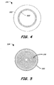
- FIG. 4 is a top view of the separate outer ring 306 of FIG. 3 .
- the separate outer ring 306 includes a flange portion 322 that is adapted to mate with a corresponding flange portion of the base transmitter housing and with a corresponding brazing ring, such as the brazing ring 312 and the flange 310 illustrated in FIG. 3 .
- the separate outer ring 306 further includes a diaphragm receiving structure 320 that is adapted to receive or interface with an attachment portion of a deformable diaphragm, such as the mounting structure 330 of the deformable diaphragm 304 illustrated in FIGS. 3 and 5 .
- FIG. 5 is a top view of the separate diaphragm 304 of FIG. 3 .
- the deformable diaphragm 304 includes the mounting structure 330 that corresponds to the diaphragm receiving structure 320 of the separate outer ring 306 illustrated in FIG. 4 .
- the deformable diaphragm 304 includes a plurality of ridges 318.
- the mounting structure 330 is adapted to mate with the diaphragm receiving structure 320 of the outer ring 306 (illustrated in FIG. 4 ) to facilitate attachment of the deformable diaphragm 304 to the separate outer ring 306.
- a resistance seam weld process is used to attach the deformable diaphragm 304 to the outer ring 306.
- a weld seam is formed between the diaphragm receiving structure 320 of the separate outer ring 306 (illustrated in FIG. 4 ) and the mounting structure 330 of the deformable diaphragm 304.
- the weld seam forms a process seal.
- resistance welding refers to a welding process in which an electrical current and pressure are applied to a work piece in order to weld the work piece to a second work piece at a joint.
- electrical resistance of the outer ring 306 to an applied electrical current results in heat that partially melts work piece material at the mounting structure 320.
- Concurrent application of pressure to the outer ring 306 and the deformable diaphragm 304 as the electrical current is applied causes a seam weld that can attach the deformable diaphragm 304 to the outer ring 306.
- the deformable diaphragm 304 may be fixed to the outer ring 306 via laser weld process, other precision weld processes, or any combination thereof.
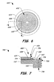
- FIG. 6 is a bottom view of a particular embodiment of a diaphragm structure 600 after an outer ring 604 is brazed to a pressure transmitter housing and after a diaphragm 602 is resistance welded to the outer ring 604.
- the diaphragm 602 includes a mounting structure 606 and a plurality of ridges 610.
- a resistance weld seam between the diaphragm 602 and the outer ring 604 is generally indicated at 608.
- the outer ring 604 can be brazed to a stainless steel housing and the diaphragm 602 can be resistance seam welded to the outer ring 604 via separate processes.
- the diaphragm 602 is welded to the outer ring 604 near an inner diameter of the outer ring 604.
- distortion resulting from the braze process is reduced for the active diaphragm area, i.e., for a portion of the diaphragm 602 that is deformable in response to fluid pressure.
- the diaphragm 602 is formed of a different material from the outer ring 604.
- the outer ring 604 may be formed from Tantalum and the deformable diaphragm 606 can be formed from Hastelloy, Gold, Zirconium, Platinum, Titanium, other materials, or any combination thereof.
- the outer ring 604 and the diaphragm 602 may have different thicknesses.
- different diaphragm thicknesses can be used to comply with customer requests and to enhance particular performance parameters, such as pressure sensitivity.
- the same outer ring 604 may be used with a variety of diaphragms having different thicknesses according to the particular implementation. Separation of the diaphragm 602 from the outer ring 604 allows for the use of attachment processes capable of welding thinner diaphragm materials on the same part so that the same outer ring 604 may be used with different deformable diaphragms 602.
- the spring rate performance of the diaphragm 602 may be improved.
- piece-to-piece performance variability may be reduced, in part, due to reduction or elimination of deformation areas at a periphery of the diaphragm 602 due to brazing. Additionally, elimination or reduction of such deformation areas enhances long-term durability.
- separation of the outer ring 604 from the diaphragm 602 allows a thicker lining to be used for a gasket area (i.e., a thicker outer ring 604 may be used) without impacting performance of the diaphragm 602.
- such separation enhances a potential for supplying parts with a Tantalum outer ring 604 with diaphragms of other material types, such as Hastelloy, Gold, Zirconium, Platinum, Titanium, other materials, or any combination thereof.
- the diaphragm material may be selected based on desired performance characteristics, availability, cost, our any combination thereof.
- FIG. 7 is a cross-sectional view 700 of the diaphragm structure 600 of FIG. 6 taken along line 7-7 in FIG. 6 .
- the diaphragm structure 600 includes an outer ring 604 coupled to a diaphragm 602 at a mounting structure 606 and a corresponding receiving structure 706 via a resistance seam weld 608.
- the diaphragm 602 includes a plurality of ridges 610.
- the outer ring 604 is coupled to a flange portion 722 of a process transmitter housing 720 via a braze joint 724.
- the process transmitter housing 720 defines a fluid cavity 726 and a capillary tube 728 that are filled with a substantially incompressible fill fluid, generally indicated at 730.
- the diaphragm 602 can deform in response to fluid pressure, compressing the substantially incompressible fill fluid 730 and applying a compressive force to the fill fluid 730.
- the applied pressure may be detected by a sensor that is coupled to the capillary tube 728, such as the sensor circuit 136 coupled to the capillary tubes 148 and 158 illustrated in FIG. 1 .
- FIG. 8 is a flow diagram of a particular illustrative embodiment of a method of manufacturing a diaphragm structure having stamped diaphragm and a separate outer ring.
- a brazing material is placed on a portion of a flange associated with a process transmitter housing.
- the flange portion may be annular and may have an inner diameter (D) that surrounds (circumscribes) a fluid cavity, such as the fluid cavity 314 illustrated in FIG. 3 .
- D inner diameter
- an outer ring is positioned on the brazing material, where the outer ring includes a diaphragm receiving structure adapted to receive a deformable diaphragm.
- the outer ring is brazed to the annular portion of the flange.
- the brazing process includes elevating a temperature of the flange, the brazing material, and the outer ring and cooling the structure to weld the outer ring to the flange.
- a deformable diaphragm is positioned at the receiving structure of the outer ring. Proceeding to 810, the deformable diaphragm is welded to the receiving structure of the outer ring. The method terminates at 812.
- FIG. 9 is a flow diagram of a second particular illustrative embodiment of a method of manufacturing a transmitter device including a stamped diaphragm and a separate outer ring.
- an outer ring is brazed to a flange of a process transmitter housing formed from a corrosion resistant material, the outer ring including a diaphragm receiving structure.
- the corrosion resistant material is stainless steel and the outer ring is formed from Tantalum.
- multiple outer rings can be brazed to respective transmitter housings concurrently.
- an attachment portion of a diaphragm is positioned onto the diaphragm receiving structure, where the diaphragm is deformable across substantially an entirety of the diameter.
- the diaphragm is selected that has a diaphragm thickness of approximately 51 ⁇ m (2 mil).
- the diaphragm is formed from Hastelloy, Gold, Zirconium, Platinum, Titanium, another material, or any combination thereof. Proceeding to 906, the diaphragm is welded to the outer ring at the attachment portion to form a weld seal between the diaphragm and the outer ring. The method terminates at 908.
- the outer ring has an inner diameter and the diaphragm receiving structure is adjacent to the inner diameter.
- the diaphragm includes a mounting structure corresponding to the diaphragm receiving structure of the outer ring, and the weld seal is formed between the diaphragm receiving structure and the mounting structure.
- welding the diaphragm to the outer ring includes positioning the mounting structure of the diaphragm relative to the diaphragm receiving structure of the outer ring, applying an electrical current to at least one of the outer ring and the diaphragm, and concurrently pressing the outer ring and the diaphragm together to resistance weld the diaphragm to the outer ring.
- the method further includes determining desired performance parameters for a process transmitter.
- desired performance parameters may be determined based on how the process transmitter is to be used.
- a material composition of the diaphragm such as Hastelloy, Gold, Zirconium, Platinum, Titanium, or other materials
- a corresponding diaphragm thickness are determined that satisfy the desired performance parameters, and the diaphragm formed from the material composition and having the corresponding diaphragm thickness is selected that satisfies the desired performance parameters.
Landscapes
- Physics & Mathematics (AREA)
- General Physics & Mathematics (AREA)
- Measuring Fluid Pressure (AREA)
Claims (15)
- Prozesstransmitter (102), der aufweist:ein korrosionsbeständiges Gehäuse (110) mit einem Flanschteil (310), wobei das korrosionsbeständige Gehäuse (110) aus einem ersten Material besteht;einen aus einem zweiten Material bestehenden Außenring (206, 306, 604), wobei der Außenring (206, 306, 604) an den Flanschteil (210, 310) angelötet ist, wobei der Außenring (206, 306, 604) einen Innendurchmesser (D) hat; undeine verformbare Membran (304, 602), die aus einem dritten Material besteht, wobei die verformbare Membran (304, 602) mit einer Schweißnaht zwischen der verformbaren Membran (304, 602) und dem Außenring (206, 306, 604), die an den Innendurchmesser (D) des Außenrings (206, 306, 604) angrenzt, so an den Außenring (206, 306, 604) angeschweißt ist, dass sich der Außenring im Durchmesser über die verformbare Membran (304, 602) hinaus erstreckt, wobei die Schweißnaht eine Fluiddichtung bildet;wobei der Außenring (206, 306, 604) eine Membranaufnahmestruktur (706) aufweist, die angrenzend an seinen Innendurchmesser (D) angeordnet ist, wobei die verformbare Membran (304, 602) eine Montagestruktur (606) aufweist, die so angepasst ist, dass sie über eine Widerstandsnahtschweißstelle (608) mit der Membranaufnahmestruktur (706) zusammenpasst, wobei die ersten, zweiten und dritten Materialien voneinander verschieden sind, und wobei die Schweißnaht zwischen der Membranaufnahmestruktur (706) und der Montagestruktur (606) ausgebildet wird.
- Prozesstransmitter nach Anspruch 1, wobei der Außenring eine erste Dicke aufweist, die größer ist als eine zweite Dicke der verformbaren Membran (304, 602).
- Prozesstransmitter nach Anspruch 1, wobei das zweite Material Tantal aufweist.
- Prozesstransmitter nach Anspruch 1, wobei das dritte Material Hastelloy oder Titan aufweist.
- Prozesstransmitter nach Anspruch 1, wobei das dritte Material Gold, Zirconium oder Platin aufweist.
- Prozesstransmitter nach Anspruch 1, wobei das erste Material Edelstahl aufweist.
- Verfahren zur Herstellung eines Prozesstransmitters (102), wobei das Verfahren aufweist:Löten eines Außenrings (206, 306, 604) an einen Flansch eines Prozesstransmittergehäuses (110), das aus einem korrosionsbeständigen ersten Material besteht, wobei der Außenring (206, 306, 604) aus einem zweiten Material besteht und eine Membranaufnahmestruktur (706) aufweist;Positionieren eines Befestigungsabschnitts einer Membran (304, 602), die aus einem dritten Material besteht, auf der Membranaufnahmestruktur (706), wobei die Membran (304, 602) quer über im Wesentlichen den gesamten Durchmesser (D) verformbar ist; undAnschweißen der Membran (304, 602) an den Außenring (206, 306, 604) an dem Befestigungsabschnitt, um eine Schweißnaht zwischen der Membran (304, 602) und dem Außenring (206, 306, 604) zu bilden, so dass sich der Außenring im Durchmesser über die verformbare Membran (304, 602) hinaus erstreckt;wobei der Außenring (206, 306, 604) eine Membranaufnahmestruktur (706) aufweist, die angrenzend an seinen Innendurchmesser (D) angeordnet ist, und wobei die verformbare Membran (304, 602) eine Montagestruktur (606) aufweist, die so angepasst ist, dass sie über eine Widerstandsnahtschweißstelle (608) mit der Membranaufnahmestruktur (706) zusammenpasst, wobei die ersten, zweiten und dritten Materialien voneinander verschieden sind, und wobei die Schweißnaht zwischen der Membranaufnahmestruktur (706) und der Montagestruktur (606) ausgebildet wird.
- Verfahren nach Anspruch 7, wobei der Außenring (206, 306, 604) einen Innendurchmesser (D) aufweist, und wobei die Membranaufnahmestruktur (706) an den Innendurchmesser (D) angrenzt.
- Verfahren nach Anspruch 8, wobei das Anschweißen der gewählten Membran (304, 602) an den Außenring (206, 306, 604) beinhaltet:Anlegen eines elektrischen Stroms an den Außenring (206, 306, 604), die Membran (304, 602) oder beide; undgleichzeitiges Zusammenpressen des Außenrings (206, 306, 604) und der Membran (304, 602), um die Membran (304, 602) durch eine Widerstandsschweißnaht an den Außenring (206, 306, 604) anzuschweißen.
- Verfahren nach Anspruch 7, wobei das Prozesstransmittergehäuse (110) aus Edelstahl besteht, und wobei der Außenring (206, 306, 604) aus Tantal besteht.
- Verfahren nach Anspruch 10, wobei die Membran (304, 602) Hastelloy, Gold, Zirconium, Platin oder Titan aufweist.
- Verfahren nach Anspruch 7, wobei die Membran (304, 602) eine Membrandicke von etwa 51 µm (2 mil) aufweist.
- Verfahren nach Anspruch 7, wobei die Auswahl der Membran (304, 602) beinhaltet:Festlegen gewünschter Leistungsparameter für einen Prozesstransmitter (102);Festlegen einer Materialzusammensetzung und einer entsprechenden Membrandicke, die den gewünschten Leistungsparametern entsprechen; undAuswahl der Membran (304, 602), die aus der Materialzusammensetzung besteht und eine entsprechende Membrandicke aufweist, die der gewünschten Leistung entsprechen.
- Verfahren nach Anspruch 7, wobei das Löten des Außenrings (206, 306, 604) das gleichzeitige Löten mehrerer Außenringe (206, 306, 604) an entsprechende Transmittergehäuse beinhaltet.
- Verfahren nach Anspruch 7, wobei der Prozesstransmitter (102) ein Druckgeber ist.
Applications Claiming Priority (2)
| Application Number | Priority Date | Filing Date | Title |
|---|---|---|---|
| US12/212,280 US7814798B2 (en) | 2008-09-17 | 2008-09-17 | Diaphragm structure and method of manufacturing a diaphragm structure |
| PCT/US2009/056579 WO2010033422A1 (en) | 2008-09-17 | 2009-09-11 | Diaphragm structure and method of manufacturing a diaphragm structure |
Publications (2)
| Publication Number | Publication Date |
|---|---|
| EP2379997A1 EP2379997A1 (de) | 2011-10-26 |
| EP2379997B1 true EP2379997B1 (de) | 2014-08-20 |
Family
ID=41395635
Family Applications (1)
| Application Number | Title | Priority Date | Filing Date |
|---|---|---|---|
| EP09792435.1A Active EP2379997B1 (de) | 2008-09-17 | 2009-09-11 | Membranstruktur und verfahren zur herstellung einer membranstruktur |
Country Status (5)
| Country | Link |
|---|---|
| US (1) | US7814798B2 (de) |
| EP (1) | EP2379997B1 (de) |
| JP (1) | JP5851241B2 (de) |
| CN (1) | CN102159928B (de) |
| WO (1) | WO2010033422A1 (de) |
Families Citing this family (25)
| Publication number | Priority date | Publication date | Assignee | Title |
|---|---|---|---|---|
| EP2113759A1 (de) * | 2008-04-29 | 2009-11-04 | The Swatch Group Research and Development Ltd. | Drucksensor mit einer ein amorphes Material enthaltenden Membran |
| DE102010043119A1 (de) * | 2010-10-29 | 2012-05-03 | Endress + Hauser Gmbh + Co. Kg | Verfahren zum Herstellen einer Verbindung zwischen zwei Keramikteilen, insbesondere von Teilen eines Drucksensors, und ein keramisches Produkt, insbesondere einen keramischen Drucksensor |
| DE102010063114A1 (de) * | 2010-12-15 | 2012-06-21 | Endress + Hauser Gmbh + Co. Kg | Flansch für Druckmesszellen oder Druckmittler-Vorrichtungen und Verfahren zur Herstellung solcher Flansche |
| DE102011005665A1 (de) | 2011-03-16 | 2012-09-20 | Endress + Hauser Gmbh + Co. Kg | Keramische Druckmesszelle und Verfahren zu ihrer Herstellung |
| US8915140B2 (en) | 2011-04-08 | 2014-12-23 | Rosemount Inc. | Corrosion resistant isolator assembly for process devices |
| WO2013134232A2 (en) * | 2012-03-06 | 2013-09-12 | Rosemount, Inc. | Remote seal pressure measurement system for subsea use |
| DE102012106236A1 (de) * | 2012-07-11 | 2014-01-16 | Endress + Hauser Gmbh + Co. Kg | Verfahren zum Fügen von Keramikkörpern mittels eines Aktivhartlots, Baugruppe mit mindestens zwei miteinander gefügten Keramikkörpern, insbesondere Druckmesszelle |
| US9442031B2 (en) | 2013-06-28 | 2016-09-13 | Rosemount Inc. | High integrity process fluid pressure probe |
| US9459170B2 (en) | 2013-09-26 | 2016-10-04 | Rosemount Inc. | Process fluid pressure sensing assembly for pressure transmitters subjected to high working pressure |
| US9103739B2 (en) | 2013-09-27 | 2015-08-11 | Rosemount Inc. | Seal for pressure transmitter for use in industrial process |
| JP6329639B2 (ja) | 2014-03-14 | 2018-05-23 | ローズマウント インコーポレイテッド | 腐蝕レート計測システム |
| US9513183B2 (en) * | 2014-06-30 | 2016-12-06 | Rosemount Inc. | Process isolation diaphragm assembly for metal process seal |
| US10830689B2 (en) | 2014-09-30 | 2020-11-10 | Rosemount Inc. | Corrosion rate measurement using sacrificial probe |
| US9638600B2 (en) | 2014-09-30 | 2017-05-02 | Rosemount Inc. | Electrical interconnect for pressure sensor in a process variable transmitter |
| US11433654B2 (en) * | 2014-11-05 | 2022-09-06 | Kulite Semiconductor Products, Inc. | Fluid-filled pressure sensor assembly capable of higher pressure environments |
| US10190968B2 (en) * | 2015-06-26 | 2019-01-29 | Rosemount Inc. | Corrosion rate measurement with multivariable sensor |
| US11226242B2 (en) | 2016-01-25 | 2022-01-18 | Rosemount Inc. | Process transmitter isolation compensation |
| US11226255B2 (en) * | 2016-09-29 | 2022-01-18 | Rosemount Inc. | Process transmitter isolation unit compensation |
| DE202016008703U1 (de) * | 2016-12-24 | 2019-02-27 | Wlka Alexander Wiegand Se & Co. Kg | Druckmittleraufbau mit evakuierter Doppelmembran und Vakuumüberwachung und kombiniertem Alarmsignal |
| WO2019222598A1 (en) | 2018-05-17 | 2019-11-21 | Rosemount Inc. | Measuring element and measuring device comprising the same |
| CN110501033B (zh) * | 2018-05-17 | 2025-12-02 | 艾默生(北京)仪表有限公司 | 测量元件及包括此种测量元件的测量装置 |
| WO2020010606A1 (en) * | 2018-07-13 | 2020-01-16 | Rosemount Inc. | Process diaphragm seal |
| CN108955982A (zh) * | 2018-08-24 | 2018-12-07 | 上海洛丁森工业自动化设备有限公司 | 一种耐辐射型压力变送器、电路板和电子装置 |
| EP3869162B1 (de) * | 2020-02-24 | 2022-07-13 | Seyonic SA | Fluiddurchflussmessvorrichtung |
| US20230010041A1 (en) * | 2021-07-12 | 2023-01-12 | Sensata Technologies, Inc. | Sensor assemblies utilizing a one-piece thermal isolated fitting tube and methods of assembling the same |
Citations (1)
| Publication number | Priority date | Publication date | Assignee | Title |
|---|---|---|---|---|
| JPH03129171A (ja) * | 1989-10-13 | 1991-06-03 | Hitachi Ltd | 圧力伝送器の製造方法 |
Family Cites Families (35)
| Publication number | Priority date | Publication date | Assignee | Title |
|---|---|---|---|---|
| US3140537A (en) | 1961-06-30 | 1964-07-14 | Du Pont | Explosive welding process |
| US3675540A (en) | 1968-07-19 | 1972-07-11 | Honeywell Inc | Diaphragm |
| US4046010A (en) | 1976-11-12 | 1977-09-06 | Beckman Instruments, Inc. | Pressure transducer with welded tantalum diaphragm |
| US4136603A (en) | 1977-11-14 | 1979-01-30 | The Foxboro Company | Diaphragm assembly |
| DE7830603U1 (de) | 1978-10-13 | 1979-05-17 | Elektromanufaktur Zangenstein Hanauer Gmbh & Co, 8471 Zangenstein | Membrandose fuer druckwaechter |
| US4541282A (en) | 1984-03-06 | 1985-09-17 | Honeywell Inc. | Method of producing a uniform fluid-tight seal between a thin, flexible member and a support and an apparatus utilizing the same |
| JPS6391531A (ja) * | 1986-10-06 | 1988-04-22 | Yamatake Honeywell Co Ltd | ダイアフラム固定構造 |
| US4885983A (en) | 1988-05-24 | 1989-12-12 | Zavoda Manufacturing Co., Inc. | Self-retaining diaphragm seal |
| DE4129414A1 (de) | 1990-11-13 | 1993-03-11 | Endress Hauser Gmbh Co | Verwendung eines speziellen tiegels beim melt-spinning einer aktivlot-legierung |
| US5110307B1 (en) | 1991-07-09 | 1994-09-20 | Balo Precision Parts Inc | Laser weldable hermetic connector |
| US5184514A (en) | 1991-07-12 | 1993-02-09 | Rosemount Inc. | Corrosion resistant isolator |
| US5230248A (en) | 1991-07-12 | 1993-07-27 | Rosemount Inc. | Corrosion resistant isolator |
| JP3089834B2 (ja) | 1992-06-22 | 2000-09-18 | 横河電機株式会社 | 差圧測定装置 |
| US5334334A (en) | 1993-03-30 | 1994-08-02 | Valence Technology, Inc. | Method of preparing lithium battery electrode compositions |
| CN1058568C (zh) | 1993-04-23 | 2000-11-15 | 罗斯蒙德公司 | 卫生处理过程中使用的压感远程隔离组件及其安装方法 |
| US5731522A (en) * | 1997-03-14 | 1998-03-24 | Rosemount Inc. | Transmitter with isolation assembly for pressure sensor |
| US6039918A (en) * | 1996-07-25 | 2000-03-21 | Endress + Hauser Gmbh + Co. | Active brazing solder for brazing alumina-ceramic parts |
| US6568274B1 (en) | 1998-02-04 | 2003-05-27 | Mks Instruments, Inc. | Capacitive based pressure sensor design |
| US6038961A (en) | 1998-03-02 | 2000-03-21 | Rosemount Inc. | Flush mount remote seal |
| JP3521322B2 (ja) * | 1998-04-21 | 2004-04-19 | 横河電機株式会社 | 差圧測定装置 |
| US6120033A (en) * | 1998-06-17 | 2000-09-19 | Rosemount Inc. | Process diaphragm seal |
| US6363790B1 (en) | 1998-10-23 | 2002-04-02 | Endress + Hauser Gmbh + Co. | Pressure sensor |
| US6267009B1 (en) | 1998-12-14 | 2001-07-31 | Endress + Hauser Gmbh + Co. | Capacitive pressure sensor cells or differential pressure sensor cells and methods for manufacturing the same |
| JP2001208631A (ja) * | 2000-01-27 | 2001-08-03 | Yokogawa Electric Corp | 差圧測定装置 |
| DE10108105A1 (de) | 2001-02-20 | 2002-10-31 | Endress & Hauser Gmbh & Co Kg | Verfahren zur Herstellung eines korrosionsbeständigen Trennkörpers |
| DE10152681A1 (de) | 2001-10-19 | 2003-04-30 | Endress & Hauser Gmbh & Co Kg | Druckmittler mit Trennmembran und Verfahren zu dessen Herstellung |
| US6675655B2 (en) * | 2002-03-21 | 2004-01-13 | Rosemount Inc. | Pressure transmitter with process coupling |
| KR100990005B1 (ko) | 2002-10-07 | 2010-10-26 | 뵈스트알파인 스탈 게엠베하 | 한쪽은 알루미늄 재료 그리고 다른 쪽은 철 또는 티탄재료로 된 두 금속판을 용접-땜납 연결에 의해 연결시키는방법 |
| US7212096B2 (en) * | 2003-01-09 | 2007-05-01 | Kulite Semiconductor Products, Inc. | Pressure sensor header having an integrated isolation diaphragm |
| US7080558B2 (en) * | 2003-10-06 | 2006-07-25 | Rosemount Inc. | Process seal for process control transmitter |
| US6945118B2 (en) | 2004-01-13 | 2005-09-20 | Honeywell International Inc. | Ceramic on metal pressure transducer |
| DE102005004942B4 (de) | 2005-02-02 | 2014-10-02 | Armaturenbau Gmbh | Verfahren zur Herstellung eines Membran-Druckmittlers |
| US20060231597A1 (en) | 2005-04-13 | 2006-10-19 | Delphi Technologies, Inc. | Method for joining a tube to a member using deformation resistance welding/brazing |
| JP4883386B2 (ja) * | 2005-08-30 | 2012-02-22 | 富士電機株式会社 | 差圧・圧力検出器 |
| US20070241169A1 (en) | 2006-04-13 | 2007-10-18 | General Electric Company | Method for welding nickel-based superalloys |
-
2008
- 2008-09-17 US US12/212,280 patent/US7814798B2/en active Active
-
2009
- 2009-09-11 WO PCT/US2009/056579 patent/WO2010033422A1/en not_active Ceased
- 2009-09-11 EP EP09792435.1A patent/EP2379997B1/de active Active
- 2009-09-11 JP JP2011526980A patent/JP5851241B2/ja not_active Expired - Fee Related
- 2009-09-11 CN CN200980136616.9A patent/CN102159928B/zh active Active
Patent Citations (1)
| Publication number | Priority date | Publication date | Assignee | Title |
|---|---|---|---|---|
| JPH03129171A (ja) * | 1989-10-13 | 1991-06-03 | Hitachi Ltd | 圧力伝送器の製造方法 |
Also Published As
| Publication number | Publication date |
|---|---|
| CN102159928A (zh) | 2011-08-17 |
| WO2010033422A1 (en) | 2010-03-25 |
| JP5851241B2 (ja) | 2016-02-03 |
| JP2012503179A (ja) | 2012-02-02 |
| US7814798B2 (en) | 2010-10-19 |
| CN102159928B (zh) | 2013-06-05 |
| US20100064816A1 (en) | 2010-03-18 |
| EP2379997A1 (de) | 2011-10-26 |
Similar Documents
| Publication | Publication Date | Title |
|---|---|---|
| EP2379997B1 (de) | Membranstruktur und verfahren zur herstellung einer membranstruktur | |
| US6038961A (en) | Flush mount remote seal | |
| US6883380B2 (en) | Pressure sensor capsule | |
| US8915140B2 (en) | Corrosion resistant isolator assembly for process devices | |
| KR101792372B1 (ko) | 압력 센서 및 그것을 사용한 매스 플로우 미터 및 매스 플로우 컨트롤러 | |
| KR101883499B1 (ko) | 정전용량형 압력센서 | |
| EP0965829B1 (de) | Isoliermembranmontage | |
| US7377174B2 (en) | Capillary weld extension with thermal isolation | |
| US20020029639A1 (en) | Isolation technique for pressure sensing structure | |
| EP3161442B1 (de) | Prozessisolierungsmembrananordnung für metallprozessdichtung | |
| CN100437067C (zh) | 用于过程控制变送器的过程密封件 | |
| EP2449355B1 (de) | Drucksender | |
| CN112689748A (zh) | 液压隔膜密封件和具有液压隔膜密封件的压力换能器 | |
| US10156491B2 (en) | Corrosion resistant pressure module for process fluid pressure transmitter | |
| EP0095284B1 (de) | Tantal-Verbindungsverfahren | |
| JP2009180621A (ja) | 差圧測定装置 | |
| JPH07103841A (ja) | 差圧伝送器 |
Legal Events
| Date | Code | Title | Description |
|---|---|---|---|
| PUAI | Public reference made under article 153(3) epc to a published international application that has entered the european phase |
Free format text: ORIGINAL CODE: 0009012 |
|
| 17P | Request for examination filed |
Effective date: 20110413 |
|
| AK | Designated contracting states |
Kind code of ref document: A1 Designated state(s): AT BE BG CH CY CZ DE DK EE ES FI FR GB GR HR HU IE IS IT LI LT LU LV MC MK MT NL NO PL PT RO SE SI SK SM TR |
|
| DAX | Request for extension of the european patent (deleted) | ||
| 17Q | First examination report despatched |
Effective date: 20130319 |
|
| REG | Reference to a national code |
Ref country code: DE Ref legal event code: R079 Ref document number: 602009026180 Country of ref document: DE Free format text: PREVIOUS MAIN CLASS: G01L0007080000 Ipc: G01L0019060000 |
|
| GRAP | Despatch of communication of intention to grant a patent |
Free format text: ORIGINAL CODE: EPIDOSNIGR1 |
|
| RIC1 | Information provided on ipc code assigned before grant |
Ipc: G01L 19/06 20060101AFI20140121BHEP Ipc: G01L 7/08 20060101ALI20140121BHEP |
|
| INTG | Intention to grant announced |
Effective date: 20140224 |
|
| GRAS | Grant fee paid |
Free format text: ORIGINAL CODE: EPIDOSNIGR3 |
|
| GRAA | (expected) grant |
Free format text: ORIGINAL CODE: 0009210 |
|
| AK | Designated contracting states |
Kind code of ref document: B1 Designated state(s): AT BE BG CH CY CZ DE DK EE ES FI FR GB GR HR HU IE IS IT LI LT LU LV MC MK MT NL NO PL PT RO SE SI SK SM TR |
|
| REG | Reference to a national code |
Ref country code: GB Ref legal event code: FG4D |
|
| REG | Reference to a national code |
Ref country code: CH Ref legal event code: NV Representative=s name: VOSSIUS AND PARTNER, CH Ref country code: CH Ref legal event code: EP |
|
| REG | Reference to a national code |
Ref country code: AT Ref legal event code: REF Ref document number: 683715 Country of ref document: AT Kind code of ref document: T Effective date: 20140915 |
|
| REG | Reference to a national code |
Ref country code: IE Ref legal event code: FG4D |
|
| REG | Reference to a national code |
Ref country code: DE Ref legal event code: R096 Ref document number: 602009026180 Country of ref document: DE Effective date: 20141002 |
|
| REG | Reference to a national code |
Ref country code: AT Ref legal event code: MK05 Ref document number: 683715 Country of ref document: AT Kind code of ref document: T Effective date: 20140820 |
|
| REG | Reference to a national code |
Ref country code: NL Ref legal event code: VDEP Effective date: 20140820 |
|
| REG | Reference to a national code |
Ref country code: LT Ref legal event code: MG4D |
|
| PG25 | Lapsed in a contracting state [announced via postgrant information from national office to epo] |
Ref country code: PT Free format text: LAPSE BECAUSE OF FAILURE TO SUBMIT A TRANSLATION OF THE DESCRIPTION OR TO PAY THE FEE WITHIN THE PRESCRIBED TIME-LIMIT Effective date: 20141222 Ref country code: GR Free format text: LAPSE BECAUSE OF FAILURE TO SUBMIT A TRANSLATION OF THE DESCRIPTION OR TO PAY THE FEE WITHIN THE PRESCRIBED TIME-LIMIT Effective date: 20141121 Ref country code: FI Free format text: LAPSE BECAUSE OF FAILURE TO SUBMIT A TRANSLATION OF THE DESCRIPTION OR TO PAY THE FEE WITHIN THE PRESCRIBED TIME-LIMIT Effective date: 20140820 Ref country code: BG Free format text: LAPSE BECAUSE OF FAILURE TO SUBMIT A TRANSLATION OF THE DESCRIPTION OR TO PAY THE FEE WITHIN THE PRESCRIBED TIME-LIMIT Effective date: 20141120 Ref country code: NO Free format text: LAPSE BECAUSE OF FAILURE TO SUBMIT A TRANSLATION OF THE DESCRIPTION OR TO PAY THE FEE WITHIN THE PRESCRIBED TIME-LIMIT Effective date: 20141120 Ref country code: ES Free format text: LAPSE BECAUSE OF FAILURE TO SUBMIT A TRANSLATION OF THE DESCRIPTION OR TO PAY THE FEE WITHIN THE PRESCRIBED TIME-LIMIT Effective date: 20140820 Ref country code: SE Free format text: LAPSE BECAUSE OF FAILURE TO SUBMIT A TRANSLATION OF THE DESCRIPTION OR TO PAY THE FEE WITHIN THE PRESCRIBED TIME-LIMIT Effective date: 20140820 Ref country code: LT Free format text: LAPSE BECAUSE OF FAILURE TO SUBMIT A TRANSLATION OF THE DESCRIPTION OR TO PAY THE FEE WITHIN THE PRESCRIBED TIME-LIMIT Effective date: 20140820 |
|
| PG25 | Lapsed in a contracting state [announced via postgrant information from national office to epo] |
Ref country code: IS Free format text: LAPSE BECAUSE OF FAILURE TO SUBMIT A TRANSLATION OF THE DESCRIPTION OR TO PAY THE FEE WITHIN THE PRESCRIBED TIME-LIMIT Effective date: 20141220 Ref country code: LV Free format text: LAPSE BECAUSE OF FAILURE TO SUBMIT A TRANSLATION OF THE DESCRIPTION OR TO PAY THE FEE WITHIN THE PRESCRIBED TIME-LIMIT Effective date: 20140820 Ref country code: AT Free format text: LAPSE BECAUSE OF FAILURE TO SUBMIT A TRANSLATION OF THE DESCRIPTION OR TO PAY THE FEE WITHIN THE PRESCRIBED TIME-LIMIT Effective date: 20140820 Ref country code: HR Free format text: LAPSE BECAUSE OF FAILURE TO SUBMIT A TRANSLATION OF THE DESCRIPTION OR TO PAY THE FEE WITHIN THE PRESCRIBED TIME-LIMIT Effective date: 20140820 |
|
| PG25 | Lapsed in a contracting state [announced via postgrant information from national office to epo] |
Ref country code: NL Free format text: LAPSE BECAUSE OF FAILURE TO SUBMIT A TRANSLATION OF THE DESCRIPTION OR TO PAY THE FEE WITHIN THE PRESCRIBED TIME-LIMIT Effective date: 20140820 |
|
| PG25 | Lapsed in a contracting state [announced via postgrant information from national office to epo] |
Ref country code: IT Free format text: LAPSE BECAUSE OF FAILURE TO SUBMIT A TRANSLATION OF THE DESCRIPTION OR TO PAY THE FEE WITHIN THE PRESCRIBED TIME-LIMIT Effective date: 20140820 Ref country code: DK Free format text: LAPSE BECAUSE OF FAILURE TO SUBMIT A TRANSLATION OF THE DESCRIPTION OR TO PAY THE FEE WITHIN THE PRESCRIBED TIME-LIMIT Effective date: 20140820 Ref country code: SK Free format text: LAPSE BECAUSE OF FAILURE TO SUBMIT A TRANSLATION OF THE DESCRIPTION OR TO PAY THE FEE WITHIN THE PRESCRIBED TIME-LIMIT Effective date: 20140820 Ref country code: CZ Free format text: LAPSE BECAUSE OF FAILURE TO SUBMIT A TRANSLATION OF THE DESCRIPTION OR TO PAY THE FEE WITHIN THE PRESCRIBED TIME-LIMIT Effective date: 20140820 Ref country code: EE Free format text: LAPSE BECAUSE OF FAILURE TO SUBMIT A TRANSLATION OF THE DESCRIPTION OR TO PAY THE FEE WITHIN THE PRESCRIBED TIME-LIMIT Effective date: 20140820 Ref country code: RO Free format text: LAPSE BECAUSE OF FAILURE TO SUBMIT A TRANSLATION OF THE DESCRIPTION OR TO PAY THE FEE WITHIN THE PRESCRIBED TIME-LIMIT Effective date: 20140820 |
|
| REG | Reference to a national code |
Ref country code: DE Ref legal event code: R097 Ref document number: 602009026180 Country of ref document: DE |
|
| PG25 | Lapsed in a contracting state [announced via postgrant information from national office to epo] |
Ref country code: MC Free format text: LAPSE BECAUSE OF FAILURE TO SUBMIT A TRANSLATION OF THE DESCRIPTION OR TO PAY THE FEE WITHIN THE PRESCRIBED TIME-LIMIT Effective date: 20140820 Ref country code: PL Free format text: LAPSE BECAUSE OF FAILURE TO SUBMIT A TRANSLATION OF THE DESCRIPTION OR TO PAY THE FEE WITHIN THE PRESCRIBED TIME-LIMIT Effective date: 20140820 |
|
| REG | Reference to a national code |
Ref country code: IE Ref legal event code: MM4A |
|
| PLBE | No opposition filed within time limit |
Free format text: ORIGINAL CODE: 0009261 |
|
| REG | Reference to a national code |
Ref country code: FR Ref legal event code: ST Effective date: 20150529 |
|
| STAA | Information on the status of an ep patent application or granted ep patent |
Free format text: STATUS: NO OPPOSITION FILED WITHIN TIME LIMIT |
|
| PG25 | Lapsed in a contracting state [announced via postgrant information from national office to epo] |
Ref country code: BE Free format text: LAPSE BECAUSE OF NON-PAYMENT OF DUE FEES Effective date: 20140930 |
|
| 26N | No opposition filed |
Effective date: 20150521 |
|
| GBPC | Gb: european patent ceased through non-payment of renewal fee |
Effective date: 20141120 |
|
| PG25 | Lapsed in a contracting state [announced via postgrant information from national office to epo] |
Ref country code: FR Free format text: LAPSE BECAUSE OF NON-PAYMENT OF DUE FEES Effective date: 20141020 Ref country code: IE Free format text: LAPSE BECAUSE OF NON-PAYMENT OF DUE FEES Effective date: 20140911 |
|
| PG25 | Lapsed in a contracting state [announced via postgrant information from national office to epo] |
Ref country code: GB Free format text: LAPSE BECAUSE OF NON-PAYMENT OF DUE FEES Effective date: 20141120 |
|
| PG25 | Lapsed in a contracting state [announced via postgrant information from national office to epo] |
Ref country code: SI Free format text: LAPSE BECAUSE OF FAILURE TO SUBMIT A TRANSLATION OF THE DESCRIPTION OR TO PAY THE FEE WITHIN THE PRESCRIBED TIME-LIMIT Effective date: 20140820 |
|
| PG25 | Lapsed in a contracting state [announced via postgrant information from national office to epo] |
Ref country code: SM Free format text: LAPSE BECAUSE OF FAILURE TO SUBMIT A TRANSLATION OF THE DESCRIPTION OR TO PAY THE FEE WITHIN THE PRESCRIBED TIME-LIMIT Effective date: 20140820 |
|
| PG25 | Lapsed in a contracting state [announced via postgrant information from national office to epo] |
Ref country code: MT Free format text: LAPSE BECAUSE OF FAILURE TO SUBMIT A TRANSLATION OF THE DESCRIPTION OR TO PAY THE FEE WITHIN THE PRESCRIBED TIME-LIMIT Effective date: 20140820 Ref country code: CY Free format text: LAPSE BECAUSE OF FAILURE TO SUBMIT A TRANSLATION OF THE DESCRIPTION OR TO PAY THE FEE WITHIN THE PRESCRIBED TIME-LIMIT Effective date: 20140820 |
|
| REG | Reference to a national code |
Ref country code: CH Ref legal event code: PFA Owner name: PI COMPONENTS CORPORATION, US Free format text: FORMER OWNER: PI COMPONENTS CORPORATION, US |
|
| PG25 | Lapsed in a contracting state [announced via postgrant information from national office to epo] |
Ref country code: HU Free format text: LAPSE BECAUSE OF FAILURE TO SUBMIT A TRANSLATION OF THE DESCRIPTION OR TO PAY THE FEE WITHIN THE PRESCRIBED TIME-LIMIT; INVALID AB INITIO Effective date: 20090911 Ref country code: BE Free format text: LAPSE BECAUSE OF FAILURE TO SUBMIT A TRANSLATION OF THE DESCRIPTION OR TO PAY THE FEE WITHIN THE PRESCRIBED TIME-LIMIT Effective date: 20140820 Ref country code: TR Free format text: LAPSE BECAUSE OF FAILURE TO SUBMIT A TRANSLATION OF THE DESCRIPTION OR TO PAY THE FEE WITHIN THE PRESCRIBED TIME-LIMIT Effective date: 20140820 Ref country code: LU Free format text: LAPSE BECAUSE OF NON-PAYMENT OF DUE FEES Effective date: 20140911 |
|
| PG25 | Lapsed in a contracting state [announced via postgrant information from national office to epo] |
Ref country code: MK Free format text: LAPSE BECAUSE OF FAILURE TO SUBMIT A TRANSLATION OF THE DESCRIPTION OR TO PAY THE FEE WITHIN THE PRESCRIBED TIME-LIMIT Effective date: 20140820 |
|
| PGFP | Annual fee paid to national office [announced via postgrant information from national office to epo] |
Ref country code: CH Payment date: 20191002 Year of fee payment: 11 |
|
| REG | Reference to a national code |
Ref country code: CH Ref legal event code: PL |
|
| PG25 | Lapsed in a contracting state [announced via postgrant information from national office to epo] |
Ref country code: CH Free format text: LAPSE BECAUSE OF NON-PAYMENT OF DUE FEES Effective date: 20200930 Ref country code: LI Free format text: LAPSE BECAUSE OF NON-PAYMENT OF DUE FEES Effective date: 20200930 |
|
| PGFP | Annual fee paid to national office [announced via postgrant information from national office to epo] |
Ref country code: DE Payment date: 20250820 Year of fee payment: 17 |