EP2379397B1 - Kontrollvorrichtung eines lenkradwinkelsensors eines kraftfahrzeugs - Google Patents
Kontrollvorrichtung eines lenkradwinkelsensors eines kraftfahrzeugs Download PDFInfo
- Publication number
- EP2379397B1 EP2379397B1 EP20090796691 EP09796691A EP2379397B1 EP 2379397 B1 EP2379397 B1 EP 2379397B1 EP 20090796691 EP20090796691 EP 20090796691 EP 09796691 A EP09796691 A EP 09796691A EP 2379397 B1 EP2379397 B1 EP 2379397B1
- Authority
- EP
- European Patent Office
- Prior art keywords
- steering wheel
- sensor
- steering
- frequency
- rotor
- Prior art date
- Legal status (The legal status is an assumption and is not a legal conclusion. Google has not performed a legal analysis and makes no representation as to the accuracy of the status listed.)
- Not-in-force
Links
Images
Classifications
-
- B—PERFORMING OPERATIONS; TRANSPORTING
- B62—LAND VEHICLES FOR TRAVELLING OTHERWISE THAN ON RAILS
- B62D—MOTOR VEHICLES; TRAILERS
- B62D15/00—Steering not otherwise provided for
- B62D15/02—Steering position indicators ; Steering position determination; Steering aids
- B62D15/021—Determination of steering angle
- B62D15/0235—Determination of steering angle by measuring or deriving directly at the electric power steering motor
Definitions
- the present invention relates to a device for controlling a position sensor of a motor vehicle equipped with a steering assistance engine.
- Today's vehicles are increasingly equipped with a power steering engine.
- Such vehicles comprise a steering system formed by a steering column carrying at its upper end a steering wheel that can be actuated by the driver of the vehicle, a rack on which acts the lower end of the steering column and a steering assistance motor in mechanical connection with the rack.
- An electronic control system controls the steering assistance engine to prevent the vehicle steering from becoming too light at usual speed or too heavy at almost zero speed.
- the angular position of the steering wheel of a vehicle can also be obtained by means of a position sensor located at the level of the assistance engine.
- the invention aims to remedy the problems of the aforementioned prior art by providing a device capable of determining, as soon as the contact of the vehicle is cut, the angular position of the steering wheel, accurately and accurately, all by ensuring a minimum power consumption and avoiding a risk of discharging the vehicle battery.
- the invention proposes a device for controlling a position sensor of a steering wheel of a motor vehicle according to claim 1.
- the invention also relates to an assisted steering system for a motor vehicle according to claim 6.
- Position sensor 13 is understood to mean a sensor making it possible to count the number of half-turn (s) or turn (s) of a rotor 8 of the motor 7 via a gear ratio operating at said rotor and the rack 6. This type of sensor is used in the steering assist motors of the engine. state of the art without benefiting from the information that can be derived from it.
- the control device 2 receives, among other things, information from the torque sensor 4 and the position sensor 13. Said information respectively reflects the torque exerted by the driver on the steering wheel 3 and the position of the rotor 8.
- the control device 2 further comprises means 9 for generating a control signal and a regulator 15 for controlling said means 9.
- the device 2 generates a control signal enabling the sensor 13 to be activated.
- the sensor 13 comprises a data storage memory 10 and a data processing module 18.
- the senor 13 When the vehicle is started by the driver, the sensor 13 is supplied with energy continuously by a power supply 14 such as a battery.
- the regulator 15 regulates the frequency of the acquisition periods of the position sensor 13 so as not to impair the operation of the power supply 14 of the vehicle by unloading it. Indeed, excessive consumption of the sensor 13 when the ignition is off would have the effect of discharging the power supply 14.
- the power consumption of the sensor 13 in standby mode is preferably less than or equal to 200 ⁇ A.
- the regulator 15 supplies the memory 10 and the means 9 for generating a control signal.
- the means 9 for generating a control signal then transmit a control signal at a predetermined frequency, called the idle frequency, to the data processing module 18. As a result, the overall power consumption of the device is decreased.
- the memory 10 makes it possible to memorize the position of the steering wheel detected previously; in other words, as soon as a change in the flying position is detected, the information is transmitted to the memory 10 which stores this information.
- the position detector 16 makes it possible to determine at any moment a change in the flying position corresponding to at least one half-turn or one revolution of the rotor 8.
- the reduction ratio can be located at the level of the steering column.
- the detector 16 detects the number of half-turn (s) or turn (s) that the rotor 8 makes.
- This information is transmitted simultaneously to the comparison module 11.
- the latter also receives information from the memory 10.
- the comparison module 11 compares the stored value with the detected value and then transmits this data to the calculation module 12.
- This calculation module 12 calculates the angular difference and / or the number of half-turn (s) or turn (s) of the rotor 8 and transmits this information to the memory 10. This information then becomes an earlier datum.
- this information is transmitted to the control device 2 and more particularly to the regulator 15.
- Said device 2 also receives data from the torque measurement sensor 4 applied by the driver to the steering wheel 3.
- said data, obtained by the torque sensor 4 and the position sensor 13 respectively allow to know the torque exerted by the driver on the steering wheel 3 and the angular position of said steering wheel 3.
- the control device 2 acts on the motor 7, which generates an assist torque via the rotor 8 providing steering assistance of the steering wheels of the vehicle.
- the sensor 13 communicates with the sensor 15 as soon as the calculation module 12 detects a change in position of the rotor 8.
- This controller will thus control the means 9 for generating a control signal, which in turn generate a control signal to the data processing module 18.
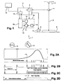
- the figure 2 illustrates two examples of control signals of the module 18 for the detection of change of flying position. These signals are pulse signals, a pulse corresponding to an acquisition period during which the module 18 is "awake” (ie performs a detection).
- the module 18 when no movement of the rotor 8 has been detected by the sensor 13, the module 18 receives a low frequency signal A.
- This idle frequency A is adapted to wake up the sensor 13 so as to do not miss a half turn or turn of the rotor 8 when the rotor 8 goes from immobility to a phase of acceleration of rotation.
- the standby frequency A is as low as possible.
- the means 9 transmit a control signal to the module 18 at an active frequency B strictly greater than the standby frequency A and adapted so as not to miss a U-turn (s) or turn (s) when the rotation speed of the steering wheel 3 is maximum
- This feature gives the sensor 13 an optimum consumption characteristic. Indeed, when no movement is detected, the consumption of the position sensor 13 is low and preferably less than or equal to 20 ⁇ A. Thus, the power supply 14 is very weakly solicited.
- the frequency is increased to switch to an active frequency B to keep awake the module 18 more often.
- the Figure 2B illustrates the invention, of varying the control frequency substantially proportional to the acceleration or deceleration of the rotational speed of the steering wheel 3. For reasons of precision it is preferable that this frequency is not below 1000 Hz.
- the preferred field of application of the invention is that of vehicles.
- the method according to the invention can be applied to any type of vehicle equipped with a steering assistance system requiring low consumption in order to ensure an optimal service life of the power supply. Therefore, the invention is applicable to buses, cars, trucks or any other type of vehicle.
Landscapes
- Engineering & Computer Science (AREA)
- Chemical & Material Sciences (AREA)
- Combustion & Propulsion (AREA)
- Transportation (AREA)
- Mechanical Engineering (AREA)
- Steering Control In Accordance With Driving Conditions (AREA)
- Power Steering Mechanism (AREA)
- Measurement Of Length, Angles, Or The Like Using Electric Or Magnetic Means (AREA)
Claims (6)
- Steuervorrichtung (2) eines Positionssensors (13) einer Lenkrads (3) eines Kraftfahrzeugs, wobei die Vorrichtung (2) Einrichtungen {9} zur Erzeugung eines Steuersignals der Erfassungsperioden des Positionssensors (13) aufweist, wenn das Fahrzeug steht, wobei die Frequenz des Signals bei der Erfassung einer Änderung der Position des Lenkrads (3) ansteigt, dadurch gekennzeichnet, dass die Einrichtungen (9) ein Signal mit einer Frequenz erzeugen, die sich proportional mit einer Beschleunigung oder einer Verlangsamung der Drehgeschwindigkeit des Lenkrads (3) ändert.
- Vorrichtung (2) nach dem vorhergehenden Anspruch, dadurch gekennzeichnet, dass die Einrichtungen (9) ein Signal mit einer Standby-Frequenz erzeugen, die geeignet ist, um eine Halbdrehung eines Rotors (8) zu erfassen.
- Vorrichtung (2) nach dem vorhergehenden Anspruch, dadurch gekennzeichnet, dass die Standby-Frequenz zwischen 500 Hz und 1000 Hz liegt.
- Vorrichtung (2) nach Anspruch 1, dadurch gekennzeichnet, dass die Einrichtungen (9) ein Signal mit einer aktiven Frequenz strikt höher als die Standby-Frequenz erzeugen, sobald der Positionssensor (13) eine Drehbewegung des Lenkrads (3) erfasst.
- Vorrichtung (2) nach mindestens einem der Ansprüche 1 bis 4, dadurch gekennzeichnet, dass die Einrichtungen (9) die aktive Frequenz verringern, um die Standby-Frequenz zu erreichen, wenn:- der Positionssensor (13) eine Verlangsamung der Drehgeschwindigkeit des Lenkrads (3) erfasst; oder- der Sensor (13) über einen bestimmten Zeitraum keine Drehung des Lenkrads (3) erfasst.
- Servolenkungssystem (1) für ein Kraftfahrzeug, dadurch gekennzeichnet, dass es mindestens aufweist:- eine Lenkstange (5), die an ihrem oberen Ende ein Lenkrad (3) trägt;- eine Zahnstange · (6), auf die das untere Ende der Lenkstange (5) einwirkt;- einen Servolenkungsmotor (7) in mechanischer Verbindung mit der Zahnstange (6);- einen der Lenkstange (5) zugeordneten Drehmomentsensor (4), der es ermöglicht, das vom Fahrer auf das Lenkrad (3) ausgeübte Drehmoment zu messen;- einen Positionssensor (13) des Lenkrads (3); wobei das System (1) dadurch gekennzeichnet ist, dass es außerdem eine Steuervorrichtung (2) nach einem der Ansprüche 1 bis 5 enthält, die es ermöglicht, den Positionssensor (13) aktiv zu halten, um die Anzahl von Halbdrehungen oder Drehungen eines Rotors (8) des Motors (7) mittels eines Untersetzungsverhältnisses zu zählen, das im Bereich des Rotors (8) und:- der Zahnstange (6); oder- der Lenkstange (5) wirkt.
Applications Claiming Priority (2)
| Application Number | Priority Date | Filing Date | Title |
|---|---|---|---|
| FR0807128A FR2940236B1 (fr) | 2008-12-18 | 2008-12-18 | Dispositif de commande d'un capteur de position d'un volant de direction d'un vehicule automobile |
| PCT/EP2009/067224 WO2010069974A1 (fr) | 2008-12-18 | 2009-12-15 | Dispositif de commande d'un capteur de position d'un volant de direction d'un vehicule automobile |
Publications (2)
| Publication Number | Publication Date |
|---|---|
| EP2379397A1 EP2379397A1 (de) | 2011-10-26 |
| EP2379397B1 true EP2379397B1 (de) | 2014-03-12 |
Family
ID=40902129
Family Applications (1)
| Application Number | Title | Priority Date | Filing Date |
|---|---|---|---|
| EP20090796691 Not-in-force EP2379397B1 (de) | 2008-12-18 | 2009-12-15 | Kontrollvorrichtung eines lenkradwinkelsensors eines kraftfahrzeugs |
Country Status (7)
| Country | Link |
|---|---|
| US (1) | US9126627B2 (de) |
| EP (1) | EP2379397B1 (de) |
| JP (1) | JP5576396B2 (de) |
| CN (1) | CN102256862B (de) |
| BR (1) | BRPI0923453A2 (de) |
| FR (1) | FR2940236B1 (de) |
| WO (1) | WO2010069974A1 (de) |
Cited By (1)
| Publication number | Priority date | Publication date | Assignee | Title |
|---|---|---|---|---|
| US20240208568A1 (en) * | 2022-12-21 | 2024-06-27 | Fca Us Llc | Power steering control system |
Families Citing this family (7)
| Publication number | Priority date | Publication date | Assignee | Title |
|---|---|---|---|---|
| DE102010043449A1 (de) * | 2010-11-05 | 2012-05-10 | Robert Bosch Gmbh | Lenkwinkelsensor für eine Servolenkung eines Kraftfahrzeugs und Verfahren |
| JP5692049B2 (ja) * | 2011-12-26 | 2015-04-01 | 株式会社デンソー | ステアリング位置制御システム |
| DE102013104586B4 (de) * | 2013-05-06 | 2016-09-15 | Robert Bosch Automotive Steering Gmbh | Verfahren zu fortlaufenden Bestimmung eines Lenkwinkels oder einer den Lenkwinkel charakterisierenden Größe |
| US20150375786A1 (en) * | 2014-06-27 | 2015-12-31 | Shu-Chen Chan | Automatic turning deceleration device for a mobility aid |
| JP2016055678A (ja) * | 2014-09-05 | 2016-04-21 | 株式会社ジェイテクト | ステアリング装置及び電動パワーステアリング装置 |
| WO2017195601A1 (ja) * | 2016-05-13 | 2017-11-16 | 日本精工株式会社 | モータ駆動制御装置、電動パワーステアリング装置及び車両 |
| JP6945944B2 (ja) | 2017-11-17 | 2021-10-06 | 三菱電機株式会社 | 回転検出装置 |
Family Cites Families (13)
| Publication number | Priority date | Publication date | Assignee | Title |
|---|---|---|---|---|
| DE69702919T2 (de) * | 1997-12-22 | 2001-01-25 | Tesa Brown & Sharpe Sa | Schaltung für Dimensionsmessgerät mit magnetoresistiven Elektroden |
| DE10145884B4 (de) * | 2001-09-18 | 2005-04-14 | Hella Kgaa Hueck & Co. | Elektronischer Winkelsensor |
| US6993439B2 (en) * | 2002-09-13 | 2006-01-31 | Innovative Scientific Solutions, Inc. | Motor based condition monitoring |
| JP4120570B2 (ja) * | 2003-11-21 | 2008-07-16 | 日産自動車株式会社 | 電動パワーステアリング装置 |
| US6977478B2 (en) * | 2004-04-29 | 2005-12-20 | International Business Machines Corporation | Method, system and program product for controlling a single phase motor |
| JP2006224805A (ja) * | 2005-02-17 | 2006-08-31 | Toyota Motor Corp | 回転位置監視装置 |
| DE102005009489A1 (de) * | 2005-02-24 | 2006-08-31 | Volkswagen Ag | Elektronikbaugruppe für eine Positionserfassungseinrichtung mit einer Weckvorrichtung zum Verarbeiten eines Aufweck-Strompulses einer Wiegand-Spule |
| JP4449840B2 (ja) * | 2005-07-05 | 2010-04-14 | トヨタ自動車株式会社 | バッテリ劣化検出装置 |
| WO2007068765A1 (de) * | 2005-12-16 | 2007-06-21 | Elmos Semiconductor Ag | Induktiver positionssensor |
| JP2008032424A (ja) * | 2006-07-26 | 2008-02-14 | Rohm Co Ltd | センサ回路、半導体装置、電子機器 |
| GB0621613D0 (en) * | 2006-10-31 | 2006-12-06 | Trw Lucasvarity Electric Steer | Electrical power assisted steering assemblies |
| US8164327B2 (en) * | 2007-08-22 | 2012-04-24 | Kostal Of America | Steering angle sensor |
| US8090468B2 (en) * | 2008-09-05 | 2012-01-03 | Mag Ias, Llc | Multi-spindle phase controlled machining |
-
2008
- 2008-12-18 FR FR0807128A patent/FR2940236B1/fr not_active Expired - Fee Related
-
2009
- 2009-12-15 CN CN200980151140.6A patent/CN102256862B/zh not_active Expired - Fee Related
- 2009-12-15 US US13/133,567 patent/US9126627B2/en not_active Expired - Fee Related
- 2009-12-15 JP JP2011541399A patent/JP5576396B2/ja not_active Expired - Fee Related
- 2009-12-15 EP EP20090796691 patent/EP2379397B1/de not_active Not-in-force
- 2009-12-15 BR BRPI0923453A patent/BRPI0923453A2/pt not_active Application Discontinuation
- 2009-12-15 WO PCT/EP2009/067224 patent/WO2010069974A1/fr not_active Ceased
Cited By (2)
| Publication number | Priority date | Publication date | Assignee | Title |
|---|---|---|---|---|
| US20240208568A1 (en) * | 2022-12-21 | 2024-06-27 | Fca Us Llc | Power steering control system |
| US12202558B2 (en) * | 2022-12-21 | 2025-01-21 | Fca Us Llc | Power steering control system |
Also Published As
| Publication number | Publication date |
|---|---|
| WO2010069974A1 (fr) | 2010-06-24 |
| CN102256862B (zh) | 2014-08-20 |
| FR2940236B1 (fr) | 2011-11-25 |
| FR2940236A1 (fr) | 2010-06-25 |
| US20110238266A1 (en) | 2011-09-29 |
| CN102256862A (zh) | 2011-11-23 |
| JP5576396B2 (ja) | 2014-08-20 |
| US9126627B2 (en) | 2015-09-08 |
| JP2012512782A (ja) | 2012-06-07 |
| EP2379397A1 (de) | 2011-10-26 |
| BRPI0923453A2 (pt) | 2016-01-12 |
Similar Documents
| Publication | Publication Date | Title |
|---|---|---|
| EP2379397B1 (de) | Kontrollvorrichtung eines lenkradwinkelsensors eines kraftfahrzeugs | |
| EP2209686B1 (de) | System zur steuerung eines fahrzeugs mit bestimmung der momentanen geschwindigkeit in relation zum boden | |
| EP2217476B1 (de) | System zur steuerung eines fahrzeugs mit bestimmung der relativen geschwindigkeit zum boden | |
| FR2811077A1 (fr) | Dispositif de determination de la position angulaire absolue d'un organe tournant | |
| FR2923437A1 (fr) | Systeme de controle du comportement d'un vehicule comportant une determination du coefficient d'adherence de roue | |
| FR2880953A1 (fr) | Capteur de roue pour detecter un mouvement du vehicule | |
| FR3032523A1 (fr) | Procede de detection d'une inclinaison par rapport au sol d'une roue | |
| WO2012085392A1 (fr) | Procede de controle d'un dispositif de direction assistee pour vehicule automobile equipe d'un systeme stop & start | |
| WO2017102072A1 (fr) | Procede d'adaptation de la strategie d'acquisition des mesures d'acceleration radiale des roues d'un vehicule | |
| FR2985113A1 (fr) | Onduleur de pilotage avec detecteur d'ondulation anormale de couple | |
| WO2013092752A1 (fr) | Onduleur de pilotage avec détecteur d'erreur de couple | |
| FR2944250A1 (fr) | Systeme electro-hydraulique d'assistance de direction pour vehicule automobile, et procede de commande associe | |
| FR2923461A1 (fr) | Procede et systeme de desactivation d'un systeme d'orientation d'un train d'atterrisage avant d'un aeronef | |
| WO2021023746A1 (fr) | Système d'acquisition et de contrôle pour véhicule à moteur électrique | |
| EP2094554B1 (de) | Verfahren zum antreiben einer elektrisch betriebenen pumpeneinheit eines durch elektrohydraulische kraft gestützten lenksystems für ein motorfahrzeug | |
| WO2011092415A1 (fr) | Systeme et procede de suivi de la trajectoire d'un vehicule | |
| WO2018104680A1 (fr) | Procédé de supervision de la vitesse d'un véhicule | |
| FR3120333A1 (fr) | Procédé et système de comptabilisation d’une distance parcourue par un véhicule automobile hybride. | |
| EP1848617B1 (de) | Scheibenwischer mit einer schutzvorrichtung für seinen elektromotor | |
| FR3062973B1 (fr) | Alterno-demarreur, vehicule automobile et procede de commande associes | |
| WO2010125289A1 (fr) | Procede et dispositif d'evaluation de l'usure d'un pneu | |
| FR2909450A1 (fr) | Procede et dispositif de determination de l'etat rotatif d'une roue d'un vehicule equipee d'un capteur actif de mouvement adapte pour delivrer un signal de sortie oscillatoire lors d'une rotation de la dite roue | |
| FR3156407A1 (fr) | Procede de surveillance d’un couple moteur dans une machine electrique de vehicule | |
| WO2025149556A1 (fr) | Unité de contrôle électronique pour système de commande de freinage | |
| WO2025120045A1 (fr) | Procédé d'estimation de l'état de santé d'une batterie et véhicule adapté à la mise en œuvre de ce procédé |
Legal Events
| Date | Code | Title | Description |
|---|---|---|---|
| PUAI | Public reference made under article 153(3) epc to a published international application that has entered the european phase |
Free format text: ORIGINAL CODE: 0009012 |
|
| 17P | Request for examination filed |
Effective date: 20110718 |
|
| AK | Designated contracting states |
Kind code of ref document: A1 Designated state(s): AT BE BG CH CY CZ DE DK EE ES FI FR GB GR HR HU IE IS IT LI LT LU LV MC MK MT NL NO PL PT RO SE SI SK SM TR |
|
| DAX | Request for extension of the european patent (deleted) | ||
| GRAP | Despatch of communication of intention to grant a patent |
Free format text: ORIGINAL CODE: EPIDOSNIGR1 |
|
| INTG | Intention to grant announced |
Effective date: 20131028 |
|
| GRAS | Grant fee paid |
Free format text: ORIGINAL CODE: EPIDOSNIGR3 |
|
| GRAA | (expected) grant |
Free format text: ORIGINAL CODE: 0009210 |
|
| AK | Designated contracting states |
Kind code of ref document: B1 Designated state(s): AT BE BG CH CY CZ DE DK EE ES FI FR GB GR HR HU IE IS IT LI LT LU LV MC MK MT NL NO PL PT RO SE SI SK SM TR |
|
| REG | Reference to a national code |
Ref country code: GB Ref legal event code: FG4D Free format text: NOT ENGLISH |
|
| REG | Reference to a national code |
Ref country code: CH Ref legal event code: EP |
|
| REG | Reference to a national code |
Ref country code: AT Ref legal event code: REF Ref document number: 656081 Country of ref document: AT Kind code of ref document: T Effective date: 20140315 |
|
| REG | Reference to a national code |
Ref country code: IE Ref legal event code: FG4D Free format text: LANGUAGE OF EP DOCUMENT: FRENCH |
|
| REG | Reference to a national code |
Ref country code: DE Ref legal event code: R096 Ref document number: 602009022486 Country of ref document: DE Effective date: 20140424 |
|
| REG | Reference to a national code |
Ref country code: NL Ref legal event code: VDEP Effective date: 20140312 |
|
| PG25 | Lapsed in a contracting state [announced via postgrant information from national office to epo] |
Ref country code: LT Free format text: LAPSE BECAUSE OF FAILURE TO SUBMIT A TRANSLATION OF THE DESCRIPTION OR TO PAY THE FEE WITHIN THE PRESCRIBED TIME-LIMIT Effective date: 20140312 Ref country code: NO Free format text: LAPSE BECAUSE OF FAILURE TO SUBMIT A TRANSLATION OF THE DESCRIPTION OR TO PAY THE FEE WITHIN THE PRESCRIBED TIME-LIMIT Effective date: 20140612 |
|
| REG | Reference to a national code |
Ref country code: AT Ref legal event code: MK05 Ref document number: 656081 Country of ref document: AT Kind code of ref document: T Effective date: 20140312 |
|
| REG | Reference to a national code |
Ref country code: LT Ref legal event code: MG4D |
|
| PG25 | Lapsed in a contracting state [announced via postgrant information from national office to epo] |
Ref country code: SE Free format text: LAPSE BECAUSE OF FAILURE TO SUBMIT A TRANSLATION OF THE DESCRIPTION OR TO PAY THE FEE WITHIN THE PRESCRIBED TIME-LIMIT Effective date: 20140312 Ref country code: FI Free format text: LAPSE BECAUSE OF FAILURE TO SUBMIT A TRANSLATION OF THE DESCRIPTION OR TO PAY THE FEE WITHIN THE PRESCRIBED TIME-LIMIT Effective date: 20140312 Ref country code: CY Free format text: LAPSE BECAUSE OF FAILURE TO SUBMIT A TRANSLATION OF THE DESCRIPTION OR TO PAY THE FEE WITHIN THE PRESCRIBED TIME-LIMIT Effective date: 20140312 |
|
| PG25 | Lapsed in a contracting state [announced via postgrant information from national office to epo] |
Ref country code: HR Free format text: LAPSE BECAUSE OF FAILURE TO SUBMIT A TRANSLATION OF THE DESCRIPTION OR TO PAY THE FEE WITHIN THE PRESCRIBED TIME-LIMIT Effective date: 20140312 Ref country code: LV Free format text: LAPSE BECAUSE OF FAILURE TO SUBMIT A TRANSLATION OF THE DESCRIPTION OR TO PAY THE FEE WITHIN THE PRESCRIBED TIME-LIMIT Effective date: 20140312 |
|
| PG25 | Lapsed in a contracting state [announced via postgrant information from national office to epo] |
Ref country code: CZ Free format text: LAPSE BECAUSE OF FAILURE TO SUBMIT A TRANSLATION OF THE DESCRIPTION OR TO PAY THE FEE WITHIN THE PRESCRIBED TIME-LIMIT Effective date: 20140312 Ref country code: IS Free format text: LAPSE BECAUSE OF FAILURE TO SUBMIT A TRANSLATION OF THE DESCRIPTION OR TO PAY THE FEE WITHIN THE PRESCRIBED TIME-LIMIT Effective date: 20140712 Ref country code: EE Free format text: LAPSE BECAUSE OF FAILURE TO SUBMIT A TRANSLATION OF THE DESCRIPTION OR TO PAY THE FEE WITHIN THE PRESCRIBED TIME-LIMIT Effective date: 20140312 Ref country code: BG Free format text: LAPSE BECAUSE OF FAILURE TO SUBMIT A TRANSLATION OF THE DESCRIPTION OR TO PAY THE FEE WITHIN THE PRESCRIBED TIME-LIMIT Effective date: 20140612 Ref country code: NL Free format text: LAPSE BECAUSE OF FAILURE TO SUBMIT A TRANSLATION OF THE DESCRIPTION OR TO PAY THE FEE WITHIN THE PRESCRIBED TIME-LIMIT Effective date: 20140312 Ref country code: RO Free format text: LAPSE BECAUSE OF FAILURE TO SUBMIT A TRANSLATION OF THE DESCRIPTION OR TO PAY THE FEE WITHIN THE PRESCRIBED TIME-LIMIT Effective date: 20140312 |
|
| PG25 | Lapsed in a contracting state [announced via postgrant information from national office to epo] |
Ref country code: ES Free format text: LAPSE BECAUSE OF FAILURE TO SUBMIT A TRANSLATION OF THE DESCRIPTION OR TO PAY THE FEE WITHIN THE PRESCRIBED TIME-LIMIT Effective date: 20140312 Ref country code: PL Free format text: LAPSE BECAUSE OF FAILURE TO SUBMIT A TRANSLATION OF THE DESCRIPTION OR TO PAY THE FEE WITHIN THE PRESCRIBED TIME-LIMIT Effective date: 20140312 Ref country code: SK Free format text: LAPSE BECAUSE OF FAILURE TO SUBMIT A TRANSLATION OF THE DESCRIPTION OR TO PAY THE FEE WITHIN THE PRESCRIBED TIME-LIMIT Effective date: 20140312 Ref country code: AT Free format text: LAPSE BECAUSE OF FAILURE TO SUBMIT A TRANSLATION OF THE DESCRIPTION OR TO PAY THE FEE WITHIN THE PRESCRIBED TIME-LIMIT Effective date: 20140312 |
|
| REG | Reference to a national code |
Ref country code: DE Ref legal event code: R097 Ref document number: 602009022486 Country of ref document: DE |
|
| PG25 | Lapsed in a contracting state [announced via postgrant information from national office to epo] |
Ref country code: PT Free format text: LAPSE BECAUSE OF FAILURE TO SUBMIT A TRANSLATION OF THE DESCRIPTION OR TO PAY THE FEE WITHIN THE PRESCRIBED TIME-LIMIT Effective date: 20140714 |
|
| PLBE | No opposition filed within time limit |
Free format text: ORIGINAL CODE: 0009261 |
|
| STAA | Information on the status of an ep patent application or granted ep patent |
Free format text: STATUS: NO OPPOSITION FILED WITHIN TIME LIMIT |
|
| PG25 | Lapsed in a contracting state [announced via postgrant information from national office to epo] |
Ref country code: DK Free format text: LAPSE BECAUSE OF FAILURE TO SUBMIT A TRANSLATION OF THE DESCRIPTION OR TO PAY THE FEE WITHIN THE PRESCRIBED TIME-LIMIT Effective date: 20140312 |
|
| 26N | No opposition filed |
Effective date: 20141215 |
|
| REG | Reference to a national code |
Ref country code: DE Ref legal event code: R097 Ref document number: 602009022486 Country of ref document: DE Effective date: 20141215 |
|
| PG25 | Lapsed in a contracting state [announced via postgrant information from national office to epo] |
Ref country code: IT Free format text: LAPSE BECAUSE OF FAILURE TO SUBMIT A TRANSLATION OF THE DESCRIPTION OR TO PAY THE FEE WITHIN THE PRESCRIBED TIME-LIMIT Effective date: 20140312 |
|
| PG25 | Lapsed in a contracting state [announced via postgrant information from national office to epo] |
Ref country code: BE Free format text: LAPSE BECAUSE OF NON-PAYMENT OF DUE FEES Effective date: 20141231 |
|
| PG25 | Lapsed in a contracting state [announced via postgrant information from national office to epo] |
Ref country code: SI Free format text: LAPSE BECAUSE OF FAILURE TO SUBMIT A TRANSLATION OF THE DESCRIPTION OR TO PAY THE FEE WITHIN THE PRESCRIBED TIME-LIMIT Effective date: 20140312 Ref country code: LU Free format text: LAPSE BECAUSE OF FAILURE TO SUBMIT A TRANSLATION OF THE DESCRIPTION OR TO PAY THE FEE WITHIN THE PRESCRIBED TIME-LIMIT Effective date: 20141215 |
|
| REG | Reference to a national code |
Ref country code: CH Ref legal event code: PL |
|
| REG | Reference to a national code |
Ref country code: IE Ref legal event code: MM4A |
|
| PG25 | Lapsed in a contracting state [announced via postgrant information from national office to epo] |
Ref country code: IE Free format text: LAPSE BECAUSE OF NON-PAYMENT OF DUE FEES Effective date: 20141215 Ref country code: LI Free format text: LAPSE BECAUSE OF NON-PAYMENT OF DUE FEES Effective date: 20141231 Ref country code: CH Free format text: LAPSE BECAUSE OF NON-PAYMENT OF DUE FEES Effective date: 20141231 |
|
| REG | Reference to a national code |
Ref country code: FR Ref legal event code: PLFP Year of fee payment: 7 |
|
| PG25 | Lapsed in a contracting state [announced via postgrant information from national office to epo] |
Ref country code: SM Free format text: LAPSE BECAUSE OF FAILURE TO SUBMIT A TRANSLATION OF THE DESCRIPTION OR TO PAY THE FEE WITHIN THE PRESCRIBED TIME-LIMIT Effective date: 20140312 |
|
| PG25 | Lapsed in a contracting state [announced via postgrant information from national office to epo] |
Ref country code: MC Free format text: LAPSE BECAUSE OF FAILURE TO SUBMIT A TRANSLATION OF THE DESCRIPTION OR TO PAY THE FEE WITHIN THE PRESCRIBED TIME-LIMIT Effective date: 20140312 |
|
| PG25 | Lapsed in a contracting state [announced via postgrant information from national office to epo] |
Ref country code: GR Free format text: LAPSE BECAUSE OF FAILURE TO SUBMIT A TRANSLATION OF THE DESCRIPTION OR TO PAY THE FEE WITHIN THE PRESCRIBED TIME-LIMIT Effective date: 20140613 |
|
| PG25 | Lapsed in a contracting state [announced via postgrant information from national office to epo] |
Ref country code: MT Free format text: LAPSE BECAUSE OF FAILURE TO SUBMIT A TRANSLATION OF THE DESCRIPTION OR TO PAY THE FEE WITHIN THE PRESCRIBED TIME-LIMIT Effective date: 20140312 Ref country code: TR Free format text: LAPSE BECAUSE OF FAILURE TO SUBMIT A TRANSLATION OF THE DESCRIPTION OR TO PAY THE FEE WITHIN THE PRESCRIBED TIME-LIMIT Effective date: 20140312 Ref country code: HU Free format text: LAPSE BECAUSE OF FAILURE TO SUBMIT A TRANSLATION OF THE DESCRIPTION OR TO PAY THE FEE WITHIN THE PRESCRIBED TIME-LIMIT; INVALID AB INITIO Effective date: 20091215 |
|
| REG | Reference to a national code |
Ref country code: FR Ref legal event code: PLFP Year of fee payment: 8 |
|
| REG | Reference to a national code |
Ref country code: FR Ref legal event code: PLFP Year of fee payment: 9 |
|
| PGFP | Annual fee paid to national office [announced via postgrant information from national office to epo] |
Ref country code: DE Payment date: 20171212 Year of fee payment: 9 |
|
| PGFP | Annual fee paid to national office [announced via postgrant information from national office to epo] |
Ref country code: GB Payment date: 20171219 Year of fee payment: 9 |
|
| PG25 | Lapsed in a contracting state [announced via postgrant information from national office to epo] |
Ref country code: MK Free format text: LAPSE BECAUSE OF FAILURE TO SUBMIT A TRANSLATION OF THE DESCRIPTION OR TO PAY THE FEE WITHIN THE PRESCRIBED TIME-LIMIT Effective date: 20140312 |
|
| REG | Reference to a national code |
Ref country code: DE Ref legal event code: R119 Ref document number: 602009022486 Country of ref document: DE |
|
| GBPC | Gb: european patent ceased through non-payment of renewal fee |
Effective date: 20181215 |
|
| PG25 | Lapsed in a contracting state [announced via postgrant information from national office to epo] |
Ref country code: DE Free format text: LAPSE BECAUSE OF NON-PAYMENT OF DUE FEES Effective date: 20190702 |
|
| PG25 | Lapsed in a contracting state [announced via postgrant information from national office to epo] |
Ref country code: GB Free format text: LAPSE BECAUSE OF NON-PAYMENT OF DUE FEES Effective date: 20181215 |
|
| PGFP | Annual fee paid to national office [announced via postgrant information from national office to epo] |
Ref country code: FR Payment date: 20211231 Year of fee payment: 13 |
|
| PG25 | Lapsed in a contracting state [announced via postgrant information from national office to epo] |
Ref country code: FR Free format text: LAPSE BECAUSE OF NON-PAYMENT OF DUE FEES Effective date: 20221231 |