EP2379397B1 - Control system for a steering wheel position sensor of a vehicle - Google Patents
Control system for a steering wheel position sensor of a vehicle Download PDFInfo
- Publication number
- EP2379397B1 EP2379397B1 EP20090796691 EP09796691A EP2379397B1 EP 2379397 B1 EP2379397 B1 EP 2379397B1 EP 20090796691 EP20090796691 EP 20090796691 EP 09796691 A EP09796691 A EP 09796691A EP 2379397 B1 EP2379397 B1 EP 2379397B1
- Authority
- EP
- European Patent Office
- Prior art keywords
- steering wheel
- sensor
- steering
- frequency
- rotor
- Prior art date
- Legal status (The legal status is an assumption and is not a legal conclusion. Google has not performed a legal analysis and makes no representation as to the accuracy of the status listed.)
- Not-in-force
Links
Images
Classifications
-
- B—PERFORMING OPERATIONS; TRANSPORTING
- B62—LAND VEHICLES FOR TRAVELLING OTHERWISE THAN ON RAILS
- B62D—MOTOR VEHICLES; TRAILERS
- B62D15/00—Steering not otherwise provided for
- B62D15/02—Steering position indicators ; Steering position determination; Steering aids
- B62D15/021—Determination of steering angle
- B62D15/0235—Determination of steering angle by measuring or deriving directly at the electric power steering motor
Definitions
- the present invention relates to a device for controlling a position sensor of a motor vehicle equipped with a steering assistance engine.
- Today's vehicles are increasingly equipped with a power steering engine.
- Such vehicles comprise a steering system formed by a steering column carrying at its upper end a steering wheel that can be actuated by the driver of the vehicle, a rack on which acts the lower end of the steering column and a steering assistance motor in mechanical connection with the rack.
- An electronic control system controls the steering assistance engine to prevent the vehicle steering from becoming too light at usual speed or too heavy at almost zero speed.
- the angular position of the steering wheel of a vehicle can also be obtained by means of a position sensor located at the level of the assistance engine.
- the invention aims to remedy the problems of the aforementioned prior art by providing a device capable of determining, as soon as the contact of the vehicle is cut, the angular position of the steering wheel, accurately and accurately, all by ensuring a minimum power consumption and avoiding a risk of discharging the vehicle battery.
- the invention proposes a device for controlling a position sensor of a steering wheel of a motor vehicle according to claim 1.
- the invention also relates to an assisted steering system for a motor vehicle according to claim 6.
- Position sensor 13 is understood to mean a sensor making it possible to count the number of half-turn (s) or turn (s) of a rotor 8 of the motor 7 via a gear ratio operating at said rotor and the rack 6. This type of sensor is used in the steering assist motors of the engine. state of the art without benefiting from the information that can be derived from it.
- the control device 2 receives, among other things, information from the torque sensor 4 and the position sensor 13. Said information respectively reflects the torque exerted by the driver on the steering wheel 3 and the position of the rotor 8.
- the control device 2 further comprises means 9 for generating a control signal and a regulator 15 for controlling said means 9.
- the device 2 generates a control signal enabling the sensor 13 to be activated.
- the sensor 13 comprises a data storage memory 10 and a data processing module 18.
- the senor 13 When the vehicle is started by the driver, the sensor 13 is supplied with energy continuously by a power supply 14 such as a battery.
- the regulator 15 regulates the frequency of the acquisition periods of the position sensor 13 so as not to impair the operation of the power supply 14 of the vehicle by unloading it. Indeed, excessive consumption of the sensor 13 when the ignition is off would have the effect of discharging the power supply 14.
- the power consumption of the sensor 13 in standby mode is preferably less than or equal to 200 ⁇ A.
- the regulator 15 supplies the memory 10 and the means 9 for generating a control signal.
- the means 9 for generating a control signal then transmit a control signal at a predetermined frequency, called the idle frequency, to the data processing module 18. As a result, the overall power consumption of the device is decreased.
- the memory 10 makes it possible to memorize the position of the steering wheel detected previously; in other words, as soon as a change in the flying position is detected, the information is transmitted to the memory 10 which stores this information.
- the position detector 16 makes it possible to determine at any moment a change in the flying position corresponding to at least one half-turn or one revolution of the rotor 8.
- the reduction ratio can be located at the level of the steering column.
- the detector 16 detects the number of half-turn (s) or turn (s) that the rotor 8 makes.
- This information is transmitted simultaneously to the comparison module 11.
- the latter also receives information from the memory 10.
- the comparison module 11 compares the stored value with the detected value and then transmits this data to the calculation module 12.
- This calculation module 12 calculates the angular difference and / or the number of half-turn (s) or turn (s) of the rotor 8 and transmits this information to the memory 10. This information then becomes an earlier datum.
- this information is transmitted to the control device 2 and more particularly to the regulator 15.
- Said device 2 also receives data from the torque measurement sensor 4 applied by the driver to the steering wheel 3.
- said data, obtained by the torque sensor 4 and the position sensor 13 respectively allow to know the torque exerted by the driver on the steering wheel 3 and the angular position of said steering wheel 3.
- the control device 2 acts on the motor 7, which generates an assist torque via the rotor 8 providing steering assistance of the steering wheels of the vehicle.
- the sensor 13 communicates with the sensor 15 as soon as the calculation module 12 detects a change in position of the rotor 8.
- This controller will thus control the means 9 for generating a control signal, which in turn generate a control signal to the data processing module 18.
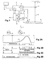
- the figure 2 illustrates two examples of control signals of the module 18 for the detection of change of flying position. These signals are pulse signals, a pulse corresponding to an acquisition period during which the module 18 is "awake” (ie performs a detection).
- the module 18 when no movement of the rotor 8 has been detected by the sensor 13, the module 18 receives a low frequency signal A.
- This idle frequency A is adapted to wake up the sensor 13 so as to do not miss a half turn or turn of the rotor 8 when the rotor 8 goes from immobility to a phase of acceleration of rotation.
- the standby frequency A is as low as possible.
- the means 9 transmit a control signal to the module 18 at an active frequency B strictly greater than the standby frequency A and adapted so as not to miss a U-turn (s) or turn (s) when the rotation speed of the steering wheel 3 is maximum
- This feature gives the sensor 13 an optimum consumption characteristic. Indeed, when no movement is detected, the consumption of the position sensor 13 is low and preferably less than or equal to 20 ⁇ A. Thus, the power supply 14 is very weakly solicited.
- the frequency is increased to switch to an active frequency B to keep awake the module 18 more often.
- the Figure 2B illustrates the invention, of varying the control frequency substantially proportional to the acceleration or deceleration of the rotational speed of the steering wheel 3. For reasons of precision it is preferable that this frequency is not below 1000 Hz.
- the preferred field of application of the invention is that of vehicles.
- the method according to the invention can be applied to any type of vehicle equipped with a steering assistance system requiring low consumption in order to ensure an optimal service life of the power supply. Therefore, the invention is applicable to buses, cars, trucks or any other type of vehicle.
Landscapes
- Engineering & Computer Science (AREA)
- Chemical & Material Sciences (AREA)
- Combustion & Propulsion (AREA)
- Transportation (AREA)
- Mechanical Engineering (AREA)
- Steering Control In Accordance With Driving Conditions (AREA)
- Power Steering Mechanism (AREA)
- Measurement Of Length, Angles, Or The Like Using Electric Or Magnetic Means (AREA)
Description
La présente invention concerne un dispositif pour commander un capteur de position d'un véhicule automobile équipé d'un moteur d'assistance à la direction.The present invention relates to a device for controlling a position sensor of a motor vehicle equipped with a steering assistance engine.
Les véhicules actuels sont de plus en plus souvent équipés de moteur d'assistance à la direction. De tels véhicules comportent un système de direction formé par une colonne de direction portant à son extrémité supérieure un volant de direction susceptible d'être actionné par le conducteur du véhicule, une crémaillère sur laquelle agit l'extrémité inférieure de la colonne de direction et un moteur d'assistance à la direction en liaison mécanique avec la crémaillère. Un système de gestion électronique de type ECU (« Electronic Control Unit ») contrôle le moteur d'assistance à la direction pour éviter que la direction du véhicule devienne trop légère à vitesse usuelle ou trop lourde à vitesse quasi-nulle.Today's vehicles are increasingly equipped with a power steering engine. Such vehicles comprise a steering system formed by a steering column carrying at its upper end a steering wheel that can be actuated by the driver of the vehicle, a rack on which acts the lower end of the steering column and a steering assistance motor in mechanical connection with the rack. An electronic control system (ECU) controls the steering assistance engine to prevent the vehicle steering from becoming too light at usual speed or too heavy at almost zero speed.
Pour le bon fonctionnement du moteur d'assistance à la direction, il est nécessaire de disposer d'une information reflétant la position angulaire du volant de direction pour assurer la fonction de retour automatique du volant de direction. Cette information est généralement fournie par un capteur volant situé au niveau du volant. La présence d'un capteur volant dédié à cette fonction entraîne toutefois un surcoût important.For proper operation of the steering assistance engine, it is necessary to have information reflecting the angular position of the steering wheel to ensure the automatic return function of the steering wheel. This information is usually provided by a steering wheel sensor located at the steering wheel. The presence of a flying sensor dedicated to this function, however, involves a significant additional cost.
La position angulaire du volant de direction d'un véhicule peut également être obtenue grâce à un capteur de position situé au niveau du moteur d'assistance à la direction.The angular position of the steering wheel of a vehicle can also be obtained by means of a position sensor located at the level of the assistance engine.
Cependant, l'utilisation de ce type de capteur pose certaines difficultés. En effet, la position du volant doit être connue à chaque instant (i.e. à l'arrêt et en roulage). De ce fait, il est nécessaire de maintenir le capteur de position du moteur d'assistance à la direction sous tension et ce même si le contact du véhicule est coupé. Un tel maintien sous tension entraîne un risque de décharge de la batterie.However, the use of this type of sensor poses certain difficulties. Indeed, the position of the steering wheel must be known at all times (ie when stopped and while driving). Therefore, it is necessary to maintain the position sensor of the assistance engine to the direction under tension even if the ignition of the vehicle is cut off. Such maintenance under voltage leads to a risk of battery discharge.
Dans ce contexte, l'invention vise à remédier aux problèmes de l'art antérieur précités en proposant un dispositif capable de déterminer, dès lors que le contact du véhicule est coupé, la position angulaire du volant de direction, avec précision et exactitude, tout en assurant une consommation électrique minimum et en évitant un risque de décharge de la batterie du véhicules.In this context, the invention aims to remedy the problems of the aforementioned prior art by providing a device capable of determining, as soon as the contact of the vehicle is cut, the angular position of the steering wheel, accurately and accurately, all by ensuring a minimum power consumption and avoiding a risk of discharging the vehicle battery.
A cette fin, l'invention propose un dispositif de commande d'un capteur de position d'un volant de direction d'un véhicule automobile selon la revendication 1.To this end, the invention proposes a device for controlling a position sensor of a steering wheel of a motor vehicle according to claim 1.
Outre les caractéristiques principales qui viennent d'être mentionnées dans le paragraphe précédent, le dispositif selon l'invention peut présenter une ou plusieurs caractéristiques supplémentaires ci-dessous, considérées individuellement ou selon toutes les combinaisons techniques possibles :
- lesdits moyens de génération d'un signal de commande génèrent un signal à une fréquence de veille adaptée pour détecter un demi-tour d'un rotor ;
- ladite fréquence de veille est comprise entre 500 Hz et 1000 Hz ;
- lesdits moyens de génération d'un signal de commande génèrent un signal à une fréquence active strictement supérieure à ladite fréquence de veille dès que le capteur de position détecte un mouvement de rotation dudit volant de direction ;
- Lesdits moyens de génération d'un signal de commande diminuent la fréquence active pour atteindre la fréquence de veille lorsque :
- le capteur de position détecte une décélération de la vitesse de rotation dudit volant ; ou
- le capteur ne détecte aucune rotation dudit volant sur une certaine période.
- said means for generating a control signal generates a signal at a standby frequency adapted to detect a half-turn of a rotor;
- said idle frequency is between 500 Hz and 1000 Hz;
- said means for generating a control signal generates a signal at an active frequency strictly greater than said standby frequency as soon as the position sensor detects a rotational movement of said steering wheel;
- Said means for generating a control signal reduce the active frequency to reach the standby frequency when:
- the position sensor detects a deceleration of the rotational speed of said steering wheel; or
- the sensor detects no rotation of said steering wheel over a period of time.
L'invention porte également sur un système de direction assisté pour véhicule automobile selon la revendication 6.The invention also relates to an assisted steering system for a motor vehicle according to
D'autres caractéristiques et avantages de l'invention ressortiront clairement de la description qui en est donnée ci-dessous, à titre indicatif et nullement limitatif, de modes de réalisations faisant références aux figures annexées ci-jointes sur lesquelles :
- La
figure 1 est une représentation schématique simplifiée d'un système de direction pour véhicule automobile et d'un dispositif de commande selon l'invention ; - La
figure 2 illustre de façon schématique différents signaux de commande du capteur de position générés par le dispositif de commande.
- The
figure 1 is a simplified schematic representation of a steering system for a motor vehicle and a control device according to the invention; - The
figure 2 schematically illustrates various control signals of the position sensor generated by the controller.
Pour des raisons de clarté, les mêmes éléments ont été désignés par des références similaires. De même, seuls les éléments utiles à la compréhension de l'invention ont été représentés, et ceci sans respect de l'échelle et de manière schématique.For the sake of clarity, the same elements have been designated by similar references. Similarly, only the elements useful for understanding the invention have been shown, and this without regard to the scale and schematically.
La
- une
colonne 5 de direction portant à son extrémité supérieure unvolant 3 de direction susceptible d'être entraîné en rotation par le conducteur du véhicule automobile ; - une
crémaillère 6 sur laquelle agit l'extrémité inférieure de lacolonne 5 de direction ; - un
moteur 7 d'assistance à la direction en liaison mécanique avec laditecrémaillère 6 ; - un capteur 4 de couple associé à la
colonne 5 de direction permettant de mesurer le couple appliqué par le conducteur sur levolant 3 ; - un
capteur 13 de position ; - un
dispositif 2 de commande permettant de maintenir éveillé lecapteur 13 de position.
- a
steering column 5 carrying at its upper end asteering wheel 3 capable of being rotated by the driver of the motor vehicle; - a
rack 6 on which acts the lower end of thesteering column 5; - a
steering assistance motor 7 in mechanical connection with saidrack 6; - a torque sensor 4 associated with the
steering column 5 for measuring the torque applied by the driver on thesteering wheel 3; - a
position sensor 13; - a
control device 2 for keeping awake theposition sensor 13.
On entend par capteur 13 de position, un capteur permettant de compter le nombre de demi-tour(s) ou de tour(s) d'un rotor 8 du moteur 7 par l'intermédiaire d'un rapport de réduction opérant au niveau dudit rotor et de la crémaillère 6. Ce type de capteur est utilisé dans les moteurs d'assistance à la direction de l'état de la technique sans pour autant tirer parti de l'information pouvant en découler.
Le dispositif 2 de commande reçoit, entre autre, des informations en provenance du capteur 4 de couple et du capteur 13 de position. Lesdites informations reflètent respectivement le couple exercé par le conducteur sur le volant 3 et la position du rotor 8.The
Le dispositif 2 de commande comprend, en outre, des moyens 9 de génération d'un signal de commande et un régulateur 15 pour commander lesdits moyens 9.The
Par ailleurs, le dispositif 2 génère un signal de commande permettant d'activer le capteur 13. Le capteur 13 comporte une mémoire 10 de stockage de données et un module 18 de traitement de données.Furthermore, the
Le module 18 de traitement des données comporte :
- un
détecteur 16 de position apte à détecter une évolution angulaire durotor 8 ; - un
module 11 de comparaison communiquant avec lamémoire 10 ; - un
module 12 de calcul.
- a
position detector 16 capable of detecting an angular evolution of therotor 8; - a
comparison module 11 communicating with thememory 10; - a
module 12 of calculation.
Lors de la mise en marche du véhicule par le conducteur, le capteur 13 est alimenté en énergie de façon continue par une alimentation 14 telle qu'une batterie.When the vehicle is started by the driver, the
En revanche, dès que le contact du véhicule est coupé, le régulateur 15 régule la fréquence des périodes d'acquisition du capteur 13 de position pour ne pas altérer le fonctionnement de l'alimentation 14 du véhicule en la déchargeant. En effet, une consommation excessive du capteur 13 lorsque le contact est éteint aurait pour action de décharger l'alimentation 14. Afin de respecter l'autonomie de l'alimentation, la consommation électrique du capteur 13 en mode veille est de préférence inférieure ou égale à 200 µA.On the other hand, as soon as the contact of the vehicle is cut off, the
Dès que le contact du véhicule est coupé, le régulateur 15 alimente la mémoire 10 et les moyens 9 de génération d'un signal de commande.As soon as the contact of the vehicle is cut off, the
Les moyens 9 de génération d'un signal de commande transmettent alors un signal de commande à une fréquence prédéterminée, dite fréquence de veille, au module 18 de traitement des données. De ce fait, la consommation électrique générale du dispositif est diminuée.The
La mémoire 10 permet de mémoriser la position du volant détectée antérieurement ; en d'autres termes, dès qu'une modification de la position volant est détectée, l'information est transmise à la mémoire 10 qui mémorise cette information.The
Parallèlement, le détecteur 16 de position permet de déterminer à tout instant une évolution de la position volant correspondant à au moins un demi-tour ou un tour du rotor 8.In parallel, the
Du fait du rapport de réduction existant entre la crémaillère 6 et le rotor 8, il est à noter que l'évolution de position dudit rotor 8 reflète avec précision et exactitude l'évolution de la position angulaire du volant 3.Due to the reduction ratio existing between the
Selon un mode de mise en oeuvre non représenté le rapport de réduction peut être situé au niveau de la colonne 5 de direction.According to an embodiment not shown, the reduction ratio can be located at the level of the steering column.
Ainsi, dès lors que le conducteur tourne le volant 3, le détecteur 16 détecte le nombre de demi-tour(s) ou de tour(s) qu'effectue le rotor 8.Thus, as soon as the driver turns the
Cette information est transmise simultanément au module 11 de comparaison. Ce dernier reçoit en outre des informations en provenance de la mémoire 10.This information is transmitted simultaneously to the
Ainsi, le module 11 de comparaison compare la valeur mémorisée avec la valeur détectée puis transmet ces données au module 12 de calcul.Thus, the
Ce module 12 de calcul, calcule la différence angulaire et/ou du nombre de demi-tour(s) ou de tour(s) du rotor 8 et transmet cette information à la mémoire 10. Cette information devient alors une donnée antérieure.This
Une fois traitées par le capteur 13, ces informations sont transmises au dispositif 2 de commande et plus particulièrement au régulateur 15.Once processed by the
Ledit dispositif 2 reçoit également des données en provenance du capteur 4 de mesure de couple appliqué par le conducteur sur le volant 3.
Ainsi, lesdites données, obtenues par le capteur 4 de couple et le capteur 13 de position permettent respectivement de connaître le couple exercé par le conducteur sur le volant 3 et la position angulaire dudit volant 3.Thus, said data, obtained by the torque sensor 4 and the
De ce fait, dès lors que le couple exercé par le conducteur dépasse un seuil prédéterminé ou est en deçà dudit seuil, le dispositif 2 de commande agit sur le moteur 7, lequel génère un couple d'assistance par l'intermédiaire du rotor 8 procurant une assistance au braquage des roues directrices du véhicule.Therefore, when the torque exerted by the driver exceeds a predetermined threshold or is below said threshold, the
En outre, le capteur 13 communique avec le capteur 15 dès lors que le module 12 de calcul détecte une évolution de position du rotor 8.In addition, the
Ce régulateur va ainsi commander les moyens 9 de génération d'un signal de commande, lesquels vont à leurs tours générer un signal de commande au module 18 de traitement des données.This controller will thus control the
A titre d'exemple, la
La courbe 2A est une représentation schématique de l'accélération de rotation du volant 3 engendrée par le conducteur du véhicule. La
- une fréquence basse A correspondant à la fréquence de veille;
- une fréquence haute B strictement supérieure à la fréquence A, correspondant à une fréquence active.
- a low frequency A corresponding to the standby frequency;
- a high frequency B strictly greater than the frequency A, corresponding to an active frequency.
Dans une telle mise en oeuvre, lorsqu'aucun mouvement du rotor 8 n'a été détecté par le capteur 13, le module 18 reçoit un signal à basse fréquence A. Cette fréquence de veille A est adaptée pour réveiller le capteur 13 de façon à ne pas manquer un demi-tour ou tour du rotor 8 lorsque le rotor 8 passe d'une immobilité à une phase d'accélération de rotation. En vue de minimiser la consommation du capteur 13 lorsqu'il n'a détecté aucun mouvement sur une certaine période, la fréquence de veille A est la plus faible possible.In such an implementation, when no movement of the
Dès qu'un mouvement de rotation du volant 3 est détecté, les moyens 9 transmettent un signal de commande au module 18 à une fréquence active B strictement supérieure à la fréquence de veille A et adaptée pour ne pas manquer de demi-tour(s) ou de tour(s) lorsque la vitesse de rotation du volant 3 est maximaleAs soon as a rotational movement of the
Cette particularité, confère au capteur 13 une caractéristique de consommation optimale. En effet, lorsqu'aucun mouvement n'est détecté, la consommation du capteur 13 de position est faible et de préférence inférieure ou égale à 20a µA. Ainsi, l'alimentation 14 est très faiblement sollicitée.This feature gives the
Puis, pour ne pas « rater » un demi-tour du rotor 8, on augmente la fréquence pour passer à une fréquence active B permettant de maintenir éveillé le module 18 plus souvent.Then, not to "miss" a half turn of the
En effet, un manque de précision angulaire serait handicapant notamment pour la fonction de retour volant offert par les dispositifs actuels d'assistance à la direction.Indeed, a lack of angular precision would be disabling especially for the flying return function offered by the current management assistance schemes.
La
Comme illustré
- lorsque le capteur 13 de position détecte une décélération ;
- à la fin d'une décélération ; ou
- lorsque ledit capteur ne détecte aucune rotation sur une certaine période.
- when the
position sensor 13 detects a deceleration; - at the end of a deceleration; or
- when said sensor detects no rotation over a period of time.
On notera que le domaine d'application privilégié de l'invention est celui des véhicules. Le procédé selon l'invention peut s'appliquer à tout type de véhicule équipé d'un système d'assistance à la direction nécessitant une faible consommation en vue d'assurer une durée de vie de l'alimentation optimale. De ce fait, l'invention est applicable aux autobus, voitures, camions ou tout autre type de véhicule.It will be noted that the preferred field of application of the invention is that of vehicles. The method according to the invention can be applied to any type of vehicle equipped with a steering assistance system requiring low consumption in order to ensure an optimal service life of the power supply. Therefore, the invention is applicable to buses, cars, trucks or any other type of vehicle.
Claims (6)
- Device (2) for controlling a sensor (13) of the position of a steering wheel (3) of a motor vehicle, said device (2) comprising means (9) for generating a control signal for the acquisition periods of the position sensor (13) when the vehicle is stationary, the frequency of said signal increasing when a change in the position of said steering wheel (3) is detected, characterized in that said means (9) generate a signal at a frequency changing proportionally with an acceleration or a deceleration of the rotation speed of said steering wheel (3).
- Device (2) according to the preceding claim, characterized in that said means (9) generate a signal at a standby frequency suitable for detecting a half-turn of a rotor (8).
- Device (2) according to the preceding claim, characterized in that said standby frequency is between 500 Hz and 1000 Hz.
- Device (2) according to Claim 1, characterized in that said means (9) generate a signal at an active frequency that is strictly higher than said standby frequency when said position sensor (13) detects a rotary movement of said steering wheel (3).
- Device (2) according to at least one of Claims 1 to 4, characterized in that said means (9) reduce said active frequency to reach said standby frequency when:- said position sensor (13) detects a deceleration of the rotation speed of said steering wheel (3); or- said sensor (13) detects no rotation of said steering wheel (3) over a certain period.
- Assisted steering system (1) for a motor vehicle, characterized in that it comprises at least:- a steering column (5) supporting at its top end a steering wheel (3);- a rack (6) on which the bottom end of said steering column (5) acts;- a power-steering motor (7) mechanically connected to said rack (6);- a torque sensor (4) associated with the steering column (5) making it possible to measure the torque applied by the driver to said steering wheel (3);- a sensor (13) of the position of the steering wheel (3);said system (1) is characterized in that it also comprises a control device (2) according to one of Claims 1 to 5 making it possible to keep said position sensor (13) alert for counting the number of half-turns or turns of a rotor (8) of said motor (7) by means of a reduction ratio operating on said rotor (8) and:- on said rack (6); or- on said steering column (5).
Applications Claiming Priority (2)
| Application Number | Priority Date | Filing Date | Title |
|---|---|---|---|
| FR0807128A FR2940236B1 (en) | 2008-12-18 | 2008-12-18 | DEVICE FOR CONTROLLING A POSITION SENSOR OF A STEERING WHEEL OF A MOTOR VEHICLE |
| PCT/EP2009/067224 WO2010069974A1 (en) | 2008-12-18 | 2009-12-15 | Device for controlling a position sensor of the steering wheel of an automobile |
Publications (2)
| Publication Number | Publication Date |
|---|---|
| EP2379397A1 EP2379397A1 (en) | 2011-10-26 |
| EP2379397B1 true EP2379397B1 (en) | 2014-03-12 |
Family
ID=40902129
Family Applications (1)
| Application Number | Title | Priority Date | Filing Date |
|---|---|---|---|
| EP20090796691 Not-in-force EP2379397B1 (en) | 2008-12-18 | 2009-12-15 | Control system for a steering wheel position sensor of a vehicle |
Country Status (7)
| Country | Link |
|---|---|
| US (1) | US9126627B2 (en) |
| EP (1) | EP2379397B1 (en) |
| JP (1) | JP5576396B2 (en) |
| CN (1) | CN102256862B (en) |
| BR (1) | BRPI0923453A2 (en) |
| FR (1) | FR2940236B1 (en) |
| WO (1) | WO2010069974A1 (en) |
Cited By (1)
| Publication number | Priority date | Publication date | Assignee | Title |
|---|---|---|---|---|
| US20240208568A1 (en) * | 2022-12-21 | 2024-06-27 | Fca Us Llc | Power steering control system |
Families Citing this family (7)
| Publication number | Priority date | Publication date | Assignee | Title |
|---|---|---|---|---|
| DE102010043449A1 (en) * | 2010-11-05 | 2012-05-10 | Robert Bosch Gmbh | Steering angle sensor for a power steering system of a motor vehicle and method |
| JP5692049B2 (en) * | 2011-12-26 | 2015-04-01 | 株式会社デンソー | Steering position control system |
| DE102013104586B4 (en) * | 2013-05-06 | 2016-09-15 | Robert Bosch Automotive Steering Gmbh | Method for continuously determining a steering angle or a variable characterizing the steering angle |
| US20150375786A1 (en) * | 2014-06-27 | 2015-12-31 | Shu-Chen Chan | Automatic turning deceleration device for a mobility aid |
| JP2016055678A (en) * | 2014-09-05 | 2016-04-21 | 株式会社ジェイテクト | Steering device and electric power steering device |
| WO2017195601A1 (en) * | 2016-05-13 | 2017-11-16 | 日本精工株式会社 | Motor drive control device, electric power steering device, and vehicle |
| CN111344213B (en) * | 2017-11-17 | 2023-10-27 | 三菱电机株式会社 | Rotation detection device |
Family Cites Families (13)
| Publication number | Priority date | Publication date | Assignee | Title |
|---|---|---|---|---|
| EP0924491B1 (en) * | 1997-12-22 | 2000-08-23 | Brown & Sharpe Tesa S.A. | Circuit for dimension measuring device with magnetoresistive electrodes |
| DE10145884B4 (en) * | 2001-09-18 | 2005-04-14 | Hella Kgaa Hueck & Co. | Electronic angle sensor |
| US6993439B2 (en) * | 2002-09-13 | 2006-01-31 | Innovative Scientific Solutions, Inc. | Motor based condition monitoring |
| JP4120570B2 (en) * | 2003-11-21 | 2008-07-16 | 日産自動車株式会社 | Electric power steering device |
| US6977478B2 (en) * | 2004-04-29 | 2005-12-20 | International Business Machines Corporation | Method, system and program product for controlling a single phase motor |
| JP2006224805A (en) * | 2005-02-17 | 2006-08-31 | Toyota Motor Corp | Rotational position monitoring device |
| DE102005009489A1 (en) * | 2005-02-24 | 2006-08-31 | Volkswagen Ag | Set of electronic components for a position-detection device has a wake-up device for processing a wakening current pulse in a Wiegand coil |
| JP4449840B2 (en) * | 2005-07-05 | 2010-04-14 | トヨタ自動車株式会社 | Battery deterioration detection device |
| EP1960740B1 (en) * | 2005-12-16 | 2013-06-26 | ELMOS Semiconductor AG | Inductive position sensor |
| JP2008032424A (en) * | 2006-07-26 | 2008-02-14 | Rohm Co Ltd | Sensor circuit, semiconductor device, electronic equipment |
| GB0621613D0 (en) * | 2006-10-31 | 2006-12-06 | Trw Lucasvarity Electric Steer | Electrical power assisted steering assemblies |
| US8164327B2 (en) * | 2007-08-22 | 2012-04-24 | Kostal Of America | Steering angle sensor |
| US8090468B2 (en) * | 2008-09-05 | 2012-01-03 | Mag Ias, Llc | Multi-spindle phase controlled machining |
-
2008
- 2008-12-18 FR FR0807128A patent/FR2940236B1/en not_active Expired - Fee Related
-
2009
- 2009-12-15 US US13/133,567 patent/US9126627B2/en not_active Expired - Fee Related
- 2009-12-15 CN CN200980151140.6A patent/CN102256862B/en not_active Expired - Fee Related
- 2009-12-15 BR BRPI0923453A patent/BRPI0923453A2/en not_active Application Discontinuation
- 2009-12-15 EP EP20090796691 patent/EP2379397B1/en not_active Not-in-force
- 2009-12-15 JP JP2011541399A patent/JP5576396B2/en not_active Expired - Fee Related
- 2009-12-15 WO PCT/EP2009/067224 patent/WO2010069974A1/en not_active Ceased
Cited By (2)
| Publication number | Priority date | Publication date | Assignee | Title |
|---|---|---|---|---|
| US20240208568A1 (en) * | 2022-12-21 | 2024-06-27 | Fca Us Llc | Power steering control system |
| US12202558B2 (en) * | 2022-12-21 | 2025-01-21 | Fca Us Llc | Power steering control system |
Also Published As
| Publication number | Publication date |
|---|---|
| BRPI0923453A2 (en) | 2016-01-12 |
| FR2940236B1 (en) | 2011-11-25 |
| FR2940236A1 (en) | 2010-06-25 |
| US9126627B2 (en) | 2015-09-08 |
| JP2012512782A (en) | 2012-06-07 |
| WO2010069974A1 (en) | 2010-06-24 |
| JP5576396B2 (en) | 2014-08-20 |
| US20110238266A1 (en) | 2011-09-29 |
| EP2379397A1 (en) | 2011-10-26 |
| CN102256862B (en) | 2014-08-20 |
| CN102256862A (en) | 2011-11-23 |
Similar Documents
| Publication | Publication Date | Title |
|---|---|---|
| EP2379397B1 (en) | Control system for a steering wheel position sensor of a vehicle | |
| EP2209686B1 (en) | System or controlling a vehicle with determination of its instantaneous speed relative to the ground | |
| EP2217476B1 (en) | System for controlling a vehicle with determination of the speed thereof relative to the ground | |
| FR2811077A1 (en) | DEVICE FOR DETERMINING THE ABSOLUTE ANGULAR POSITION OF A ROTATING BODY | |
| FR2923437A1 (en) | SYSTEM FOR MONITORING THE BEHAVIOR OF A VEHICLE COMPRISING A DETERMINATION OF THE WHEEL ADHESION COEFFICIENT | |
| FR2880953A1 (en) | WHEEL SENSOR FOR DETECTING MOVEMENT OF VEHICLE | |
| WO2016128114A1 (en) | Method for detecting an inclination of a wheel relative to the horizontal | |
| WO2012085392A1 (en) | Method for controlling a power steering device for a motor vehicle equipped with a stop & start system | |
| WO2017102072A1 (en) | Method for adapting the strategy for acquiring measurements of radial acceleration of the wheels of a vehicle | |
| FR2985113A1 (en) | PILOT INVERTER WITH ABNORMAL TORQUE DETECTION DETECTOR | |
| EP3111244A1 (en) | Method for measuring the ageing of permanent magnets of a synchronous machine fitted with an angular position sensor | |
| EP2794336A1 (en) | Drive inverter having a torque error detector | |
| FR2944250A1 (en) | ELECTRO-HYDRAULIC STEERING ASSISTANCE SYSTEM FOR MOTOR VEHICLE, AND CONTROL METHOD THEREOF | |
| FR2923461A1 (en) | METHOD AND SYSTEM FOR DEACTIVATION OF A SYSTEM FOR ORIENTING A LANDING TRAIN BEFORE AN AIRCRAFT | |
| WO2021023746A1 (en) | Acquiring and control system for a vehicle comprising an electric motor | |
| EP2094554B1 (en) | Method for driving an electrically operated pump unit of a motor vehicle electrohydraulic power-assisted steering system | |
| WO2018104680A1 (en) | Device for monitoring the speed of a vehicle | |
| FR3120333A1 (en) | Method and system for counting a distance traveled by a hybrid motor vehicle. | |
| EP1848617B1 (en) | Windscreen wiper comprising a protection device for the electric motor thereof | |
| FR3062973B1 (en) | ALTERNOMETER, MOTOR VEHICLE AND CONTROL METHOD THEREOF | |
| FR2909450A1 (en) | METHOD AND DEVICE FOR DETERMINING THE ROTARY STATUS OF A WHEEL OF A VEHICLE EQUIPPED WITH AN ACTIVE MOTION SENSOR ADAPTED TO DELIVER AN OSCILLATORY OUTPUT SIGNAL WHEN ROTATING THE WHEEL | |
| FR3156407A1 (en) | METHOD FOR MONITORING ENGINE TORQUE IN AN ELECTRIC VEHICLE MACHINE | |
| WO2025149556A1 (en) | Electronic control unit for a braking control system | |
| WO2025120045A1 (en) | Method for estimating the state of health of a battery and vehicle suitable for implementing this method | |
| EP2451660A1 (en) | Method and device for detecting an inadmissible degree of inflation of a tyre |
Legal Events
| Date | Code | Title | Description |
|---|---|---|---|
| PUAI | Public reference made under article 153(3) epc to a published international application that has entered the european phase |
Free format text: ORIGINAL CODE: 0009012 |
|
| 17P | Request for examination filed |
Effective date: 20110718 |
|
| AK | Designated contracting states |
Kind code of ref document: A1 Designated state(s): AT BE BG CH CY CZ DE DK EE ES FI FR GB GR HR HU IE IS IT LI LT LU LV MC MK MT NL NO PL PT RO SE SI SK SM TR |
|
| DAX | Request for extension of the european patent (deleted) | ||
| GRAP | Despatch of communication of intention to grant a patent |
Free format text: ORIGINAL CODE: EPIDOSNIGR1 |
|
| INTG | Intention to grant announced |
Effective date: 20131028 |
|
| GRAS | Grant fee paid |
Free format text: ORIGINAL CODE: EPIDOSNIGR3 |
|
| GRAA | (expected) grant |
Free format text: ORIGINAL CODE: 0009210 |
|
| AK | Designated contracting states |
Kind code of ref document: B1 Designated state(s): AT BE BG CH CY CZ DE DK EE ES FI FR GB GR HR HU IE IS IT LI LT LU LV MC MK MT NL NO PL PT RO SE SI SK SM TR |
|
| REG | Reference to a national code |
Ref country code: GB Ref legal event code: FG4D Free format text: NOT ENGLISH |
|
| REG | Reference to a national code |
Ref country code: CH Ref legal event code: EP |
|
| REG | Reference to a national code |
Ref country code: AT Ref legal event code: REF Ref document number: 656081 Country of ref document: AT Kind code of ref document: T Effective date: 20140315 |
|
| REG | Reference to a national code |
Ref country code: IE Ref legal event code: FG4D Free format text: LANGUAGE OF EP DOCUMENT: FRENCH |
|
| REG | Reference to a national code |
Ref country code: DE Ref legal event code: R096 Ref document number: 602009022486 Country of ref document: DE Effective date: 20140424 |
|
| REG | Reference to a national code |
Ref country code: NL Ref legal event code: VDEP Effective date: 20140312 |
|
| PG25 | Lapsed in a contracting state [announced via postgrant information from national office to epo] |
Ref country code: LT Free format text: LAPSE BECAUSE OF FAILURE TO SUBMIT A TRANSLATION OF THE DESCRIPTION OR TO PAY THE FEE WITHIN THE PRESCRIBED TIME-LIMIT Effective date: 20140312 Ref country code: NO Free format text: LAPSE BECAUSE OF FAILURE TO SUBMIT A TRANSLATION OF THE DESCRIPTION OR TO PAY THE FEE WITHIN THE PRESCRIBED TIME-LIMIT Effective date: 20140612 |
|
| REG | Reference to a national code |
Ref country code: AT Ref legal event code: MK05 Ref document number: 656081 Country of ref document: AT Kind code of ref document: T Effective date: 20140312 |
|
| REG | Reference to a national code |
Ref country code: LT Ref legal event code: MG4D |
|
| PG25 | Lapsed in a contracting state [announced via postgrant information from national office to epo] |
Ref country code: SE Free format text: LAPSE BECAUSE OF FAILURE TO SUBMIT A TRANSLATION OF THE DESCRIPTION OR TO PAY THE FEE WITHIN THE PRESCRIBED TIME-LIMIT Effective date: 20140312 Ref country code: FI Free format text: LAPSE BECAUSE OF FAILURE TO SUBMIT A TRANSLATION OF THE DESCRIPTION OR TO PAY THE FEE WITHIN THE PRESCRIBED TIME-LIMIT Effective date: 20140312 Ref country code: CY Free format text: LAPSE BECAUSE OF FAILURE TO SUBMIT A TRANSLATION OF THE DESCRIPTION OR TO PAY THE FEE WITHIN THE PRESCRIBED TIME-LIMIT Effective date: 20140312 |
|
| PG25 | Lapsed in a contracting state [announced via postgrant information from national office to epo] |
Ref country code: HR Free format text: LAPSE BECAUSE OF FAILURE TO SUBMIT A TRANSLATION OF THE DESCRIPTION OR TO PAY THE FEE WITHIN THE PRESCRIBED TIME-LIMIT Effective date: 20140312 Ref country code: LV Free format text: LAPSE BECAUSE OF FAILURE TO SUBMIT A TRANSLATION OF THE DESCRIPTION OR TO PAY THE FEE WITHIN THE PRESCRIBED TIME-LIMIT Effective date: 20140312 |
|
| PG25 | Lapsed in a contracting state [announced via postgrant information from national office to epo] |
Ref country code: CZ Free format text: LAPSE BECAUSE OF FAILURE TO SUBMIT A TRANSLATION OF THE DESCRIPTION OR TO PAY THE FEE WITHIN THE PRESCRIBED TIME-LIMIT Effective date: 20140312 Ref country code: IS Free format text: LAPSE BECAUSE OF FAILURE TO SUBMIT A TRANSLATION OF THE DESCRIPTION OR TO PAY THE FEE WITHIN THE PRESCRIBED TIME-LIMIT Effective date: 20140712 Ref country code: EE Free format text: LAPSE BECAUSE OF FAILURE TO SUBMIT A TRANSLATION OF THE DESCRIPTION OR TO PAY THE FEE WITHIN THE PRESCRIBED TIME-LIMIT Effective date: 20140312 Ref country code: BG Free format text: LAPSE BECAUSE OF FAILURE TO SUBMIT A TRANSLATION OF THE DESCRIPTION OR TO PAY THE FEE WITHIN THE PRESCRIBED TIME-LIMIT Effective date: 20140612 Ref country code: NL Free format text: LAPSE BECAUSE OF FAILURE TO SUBMIT A TRANSLATION OF THE DESCRIPTION OR TO PAY THE FEE WITHIN THE PRESCRIBED TIME-LIMIT Effective date: 20140312 Ref country code: RO Free format text: LAPSE BECAUSE OF FAILURE TO SUBMIT A TRANSLATION OF THE DESCRIPTION OR TO PAY THE FEE WITHIN THE PRESCRIBED TIME-LIMIT Effective date: 20140312 |
|
| PG25 | Lapsed in a contracting state [announced via postgrant information from national office to epo] |
Ref country code: ES Free format text: LAPSE BECAUSE OF FAILURE TO SUBMIT A TRANSLATION OF THE DESCRIPTION OR TO PAY THE FEE WITHIN THE PRESCRIBED TIME-LIMIT Effective date: 20140312 Ref country code: PL Free format text: LAPSE BECAUSE OF FAILURE TO SUBMIT A TRANSLATION OF THE DESCRIPTION OR TO PAY THE FEE WITHIN THE PRESCRIBED TIME-LIMIT Effective date: 20140312 Ref country code: SK Free format text: LAPSE BECAUSE OF FAILURE TO SUBMIT A TRANSLATION OF THE DESCRIPTION OR TO PAY THE FEE WITHIN THE PRESCRIBED TIME-LIMIT Effective date: 20140312 Ref country code: AT Free format text: LAPSE BECAUSE OF FAILURE TO SUBMIT A TRANSLATION OF THE DESCRIPTION OR TO PAY THE FEE WITHIN THE PRESCRIBED TIME-LIMIT Effective date: 20140312 |
|
| REG | Reference to a national code |
Ref country code: DE Ref legal event code: R097 Ref document number: 602009022486 Country of ref document: DE |
|
| PG25 | Lapsed in a contracting state [announced via postgrant information from national office to epo] |
Ref country code: PT Free format text: LAPSE BECAUSE OF FAILURE TO SUBMIT A TRANSLATION OF THE DESCRIPTION OR TO PAY THE FEE WITHIN THE PRESCRIBED TIME-LIMIT Effective date: 20140714 |
|
| PLBE | No opposition filed within time limit |
Free format text: ORIGINAL CODE: 0009261 |
|
| STAA | Information on the status of an ep patent application or granted ep patent |
Free format text: STATUS: NO OPPOSITION FILED WITHIN TIME LIMIT |
|
| PG25 | Lapsed in a contracting state [announced via postgrant information from national office to epo] |
Ref country code: DK Free format text: LAPSE BECAUSE OF FAILURE TO SUBMIT A TRANSLATION OF THE DESCRIPTION OR TO PAY THE FEE WITHIN THE PRESCRIBED TIME-LIMIT Effective date: 20140312 |
|
| 26N | No opposition filed |
Effective date: 20141215 |
|
| REG | Reference to a national code |
Ref country code: DE Ref legal event code: R097 Ref document number: 602009022486 Country of ref document: DE Effective date: 20141215 |
|
| PG25 | Lapsed in a contracting state [announced via postgrant information from national office to epo] |
Ref country code: IT Free format text: LAPSE BECAUSE OF FAILURE TO SUBMIT A TRANSLATION OF THE DESCRIPTION OR TO PAY THE FEE WITHIN THE PRESCRIBED TIME-LIMIT Effective date: 20140312 |
|
| PG25 | Lapsed in a contracting state [announced via postgrant information from national office to epo] |
Ref country code: BE Free format text: LAPSE BECAUSE OF NON-PAYMENT OF DUE FEES Effective date: 20141231 |
|
| PG25 | Lapsed in a contracting state [announced via postgrant information from national office to epo] |
Ref country code: SI Free format text: LAPSE BECAUSE OF FAILURE TO SUBMIT A TRANSLATION OF THE DESCRIPTION OR TO PAY THE FEE WITHIN THE PRESCRIBED TIME-LIMIT Effective date: 20140312 Ref country code: LU Free format text: LAPSE BECAUSE OF FAILURE TO SUBMIT A TRANSLATION OF THE DESCRIPTION OR TO PAY THE FEE WITHIN THE PRESCRIBED TIME-LIMIT Effective date: 20141215 |
|
| REG | Reference to a national code |
Ref country code: CH Ref legal event code: PL |
|
| REG | Reference to a national code |
Ref country code: IE Ref legal event code: MM4A |
|
| PG25 | Lapsed in a contracting state [announced via postgrant information from national office to epo] |
Ref country code: IE Free format text: LAPSE BECAUSE OF NON-PAYMENT OF DUE FEES Effective date: 20141215 Ref country code: LI Free format text: LAPSE BECAUSE OF NON-PAYMENT OF DUE FEES Effective date: 20141231 Ref country code: CH Free format text: LAPSE BECAUSE OF NON-PAYMENT OF DUE FEES Effective date: 20141231 |
|
| REG | Reference to a national code |
Ref country code: FR Ref legal event code: PLFP Year of fee payment: 7 |
|
| PG25 | Lapsed in a contracting state [announced via postgrant information from national office to epo] |
Ref country code: SM Free format text: LAPSE BECAUSE OF FAILURE TO SUBMIT A TRANSLATION OF THE DESCRIPTION OR TO PAY THE FEE WITHIN THE PRESCRIBED TIME-LIMIT Effective date: 20140312 |
|
| PG25 | Lapsed in a contracting state [announced via postgrant information from national office to epo] |
Ref country code: MC Free format text: LAPSE BECAUSE OF FAILURE TO SUBMIT A TRANSLATION OF THE DESCRIPTION OR TO PAY THE FEE WITHIN THE PRESCRIBED TIME-LIMIT Effective date: 20140312 |
|
| PG25 | Lapsed in a contracting state [announced via postgrant information from national office to epo] |
Ref country code: GR Free format text: LAPSE BECAUSE OF FAILURE TO SUBMIT A TRANSLATION OF THE DESCRIPTION OR TO PAY THE FEE WITHIN THE PRESCRIBED TIME-LIMIT Effective date: 20140613 |
|
| PG25 | Lapsed in a contracting state [announced via postgrant information from national office to epo] |
Ref country code: MT Free format text: LAPSE BECAUSE OF FAILURE TO SUBMIT A TRANSLATION OF THE DESCRIPTION OR TO PAY THE FEE WITHIN THE PRESCRIBED TIME-LIMIT Effective date: 20140312 Ref country code: TR Free format text: LAPSE BECAUSE OF FAILURE TO SUBMIT A TRANSLATION OF THE DESCRIPTION OR TO PAY THE FEE WITHIN THE PRESCRIBED TIME-LIMIT Effective date: 20140312 Ref country code: HU Free format text: LAPSE BECAUSE OF FAILURE TO SUBMIT A TRANSLATION OF THE DESCRIPTION OR TO PAY THE FEE WITHIN THE PRESCRIBED TIME-LIMIT; INVALID AB INITIO Effective date: 20091215 |
|
| REG | Reference to a national code |
Ref country code: FR Ref legal event code: PLFP Year of fee payment: 8 |
|
| REG | Reference to a national code |
Ref country code: FR Ref legal event code: PLFP Year of fee payment: 9 |
|
| PGFP | Annual fee paid to national office [announced via postgrant information from national office to epo] |
Ref country code: DE Payment date: 20171212 Year of fee payment: 9 |
|
| PGFP | Annual fee paid to national office [announced via postgrant information from national office to epo] |
Ref country code: GB Payment date: 20171219 Year of fee payment: 9 |
|
| PG25 | Lapsed in a contracting state [announced via postgrant information from national office to epo] |
Ref country code: MK Free format text: LAPSE BECAUSE OF FAILURE TO SUBMIT A TRANSLATION OF THE DESCRIPTION OR TO PAY THE FEE WITHIN THE PRESCRIBED TIME-LIMIT Effective date: 20140312 |
|
| REG | Reference to a national code |
Ref country code: DE Ref legal event code: R119 Ref document number: 602009022486 Country of ref document: DE |
|
| GBPC | Gb: european patent ceased through non-payment of renewal fee |
Effective date: 20181215 |
|
| PG25 | Lapsed in a contracting state [announced via postgrant information from national office to epo] |
Ref country code: DE Free format text: LAPSE BECAUSE OF NON-PAYMENT OF DUE FEES Effective date: 20190702 |
|
| PG25 | Lapsed in a contracting state [announced via postgrant information from national office to epo] |
Ref country code: GB Free format text: LAPSE BECAUSE OF NON-PAYMENT OF DUE FEES Effective date: 20181215 |
|
| PGFP | Annual fee paid to national office [announced via postgrant information from national office to epo] |
Ref country code: FR Payment date: 20211231 Year of fee payment: 13 |
|
| PG25 | Lapsed in a contracting state [announced via postgrant information from national office to epo] |
Ref country code: FR Free format text: LAPSE BECAUSE OF NON-PAYMENT OF DUE FEES Effective date: 20221231 |