EP2379010B2 - Vorrichtung zur feineinstellung einer perkutanen klappenstruktur - Google Patents
Vorrichtung zur feineinstellung einer perkutanen klappenstruktur Download PDFInfo
- Publication number
- EP2379010B2 EP2379010B2 EP10702540.5A EP10702540A EP2379010B2 EP 2379010 B2 EP2379010 B2 EP 2379010B2 EP 10702540 A EP10702540 A EP 10702540A EP 2379010 B2 EP2379010 B2 EP 2379010B2
- Authority
- EP
- European Patent Office
- Prior art keywords
- valve
- percutaneous
- valve member
- valve device
- device frame
- Prior art date
- Legal status (The legal status is an assumption and is not a legal conclusion. Google has not performed a legal analysis and makes no representation as to the accuracy of the status listed.)
- Active
Links
Images


Classifications
-
- A—HUMAN NECESSITIES
- A61—MEDICAL OR VETERINARY SCIENCE; HYGIENE
- A61F—FILTERS IMPLANTABLE INTO BLOOD VESSELS; PROSTHESES; DEVICES PROVIDING PATENCY TO, OR PREVENTING COLLAPSING OF, TUBULAR STRUCTURES OF THE BODY, e.g. STENTS; ORTHOPAEDIC, NURSING OR CONTRACEPTIVE DEVICES; FOMENTATION; TREATMENT OR PROTECTION OF EYES OR EARS; BANDAGES, DRESSINGS OR ABSORBENT PADS; FIRST-AID KITS
- A61F2/00—Filters implantable into blood vessels; Prostheses, i.e. artificial substitutes or replacements for parts of the body; Appliances for connecting them with the body; Devices providing patency to, or preventing collapsing of, tubular structures of the body, e.g. stents
- A61F2/02—Prostheses implantable into the body
- A61F2/24—Heart valves ; Vascular valves, e.g. venous valves; Heart implants, e.g. passive devices for improving the function of the native valve or the heart muscle; Transmyocardial revascularisation [TMR] devices; Valves implantable in the body
-
- A—HUMAN NECESSITIES
- A61—MEDICAL OR VETERINARY SCIENCE; HYGIENE
- A61F—FILTERS IMPLANTABLE INTO BLOOD VESSELS; PROSTHESES; DEVICES PROVIDING PATENCY TO, OR PREVENTING COLLAPSING OF, TUBULAR STRUCTURES OF THE BODY, e.g. STENTS; ORTHOPAEDIC, NURSING OR CONTRACEPTIVE DEVICES; FOMENTATION; TREATMENT OR PROTECTION OF EYES OR EARS; BANDAGES, DRESSINGS OR ABSORBENT PADS; FIRST-AID KITS
- A61F2/00—Filters implantable into blood vessels; Prostheses, i.e. artificial substitutes or replacements for parts of the body; Appliances for connecting them with the body; Devices providing patency to, or preventing collapsing of, tubular structures of the body, e.g. stents
- A61F2/02—Prostheses implantable into the body
- A61F2/24—Heart valves ; Vascular valves, e.g. venous valves; Heart implants, e.g. passive devices for improving the function of the native valve or the heart muscle; Transmyocardial revascularisation [TMR] devices; Valves implantable in the body
- A61F2/2412—Heart valves ; Vascular valves, e.g. venous valves; Heart implants, e.g. passive devices for improving the function of the native valve or the heart muscle; Transmyocardial revascularisation [TMR] devices; Valves implantable in the body with soft flexible valve members, e.g. tissue valves shaped like natural valves
- A61F2/2418—Scaffolds therefor, e.g. support stents
-
- A—HUMAN NECESSITIES
- A61—MEDICAL OR VETERINARY SCIENCE; HYGIENE
- A61F—FILTERS IMPLANTABLE INTO BLOOD VESSELS; PROSTHESES; DEVICES PROVIDING PATENCY TO, OR PREVENTING COLLAPSING OF, TUBULAR STRUCTURES OF THE BODY, e.g. STENTS; ORTHOPAEDIC, NURSING OR CONTRACEPTIVE DEVICES; FOMENTATION; TREATMENT OR PROTECTION OF EYES OR EARS; BANDAGES, DRESSINGS OR ABSORBENT PADS; FIRST-AID KITS
- A61F2/00—Filters implantable into blood vessels; Prostheses, i.e. artificial substitutes or replacements for parts of the body; Appliances for connecting them with the body; Devices providing patency to, or preventing collapsing of, tubular structures of the body, e.g. stents
- A61F2/02—Prostheses implantable into the body
- A61F2/24—Heart valves ; Vascular valves, e.g. venous valves; Heart implants, e.g. passive devices for improving the function of the native valve or the heart muscle; Transmyocardial revascularisation [TMR] devices; Valves implantable in the body
- A61F2/2409—Support rings therefor, e.g. for connecting valves to tissue
-
- A—HUMAN NECESSITIES
- A61—MEDICAL OR VETERINARY SCIENCE; HYGIENE
- A61F—FILTERS IMPLANTABLE INTO BLOOD VESSELS; PROSTHESES; DEVICES PROVIDING PATENCY TO, OR PREVENTING COLLAPSING OF, TUBULAR STRUCTURES OF THE BODY, e.g. STENTS; ORTHOPAEDIC, NURSING OR CONTRACEPTIVE DEVICES; FOMENTATION; TREATMENT OR PROTECTION OF EYES OR EARS; BANDAGES, DRESSINGS OR ABSORBENT PADS; FIRST-AID KITS
- A61F2/00—Filters implantable into blood vessels; Prostheses, i.e. artificial substitutes or replacements for parts of the body; Appliances for connecting them with the body; Devices providing patency to, or preventing collapsing of, tubular structures of the body, e.g. stents
- A61F2/02—Prostheses implantable into the body
- A61F2/24—Heart valves ; Vascular valves, e.g. venous valves; Heart implants, e.g. passive devices for improving the function of the native valve or the heart muscle; Transmyocardial revascularisation [TMR] devices; Valves implantable in the body
- A61F2/2412—Heart valves ; Vascular valves, e.g. venous valves; Heart implants, e.g. passive devices for improving the function of the native valve or the heart muscle; Transmyocardial revascularisation [TMR] devices; Valves implantable in the body with soft flexible valve members, e.g. tissue valves shaped like natural valves
-
- A—HUMAN NECESSITIES
- A61—MEDICAL OR VETERINARY SCIENCE; HYGIENE
- A61F—FILTERS IMPLANTABLE INTO BLOOD VESSELS; PROSTHESES; DEVICES PROVIDING PATENCY TO, OR PREVENTING COLLAPSING OF, TUBULAR STRUCTURES OF THE BODY, e.g. STENTS; ORTHOPAEDIC, NURSING OR CONTRACEPTIVE DEVICES; FOMENTATION; TREATMENT OR PROTECTION OF EYES OR EARS; BANDAGES, DRESSINGS OR ABSORBENT PADS; FIRST-AID KITS
- A61F2/00—Filters implantable into blood vessels; Prostheses, i.e. artificial substitutes or replacements for parts of the body; Appliances for connecting them with the body; Devices providing patency to, or preventing collapsing of, tubular structures of the body, e.g. stents
- A61F2/02—Prostheses implantable into the body
- A61F2/24—Heart valves ; Vascular valves, e.g. venous valves; Heart implants, e.g. passive devices for improving the function of the native valve or the heart muscle; Transmyocardial revascularisation [TMR] devices; Valves implantable in the body
- A61F2/2427—Devices for manipulating or deploying heart valves during implantation
-
- A—HUMAN NECESSITIES
- A61—MEDICAL OR VETERINARY SCIENCE; HYGIENE
- A61F—FILTERS IMPLANTABLE INTO BLOOD VESSELS; PROSTHESES; DEVICES PROVIDING PATENCY TO, OR PREVENTING COLLAPSING OF, TUBULAR STRUCTURES OF THE BODY, e.g. STENTS; ORTHOPAEDIC, NURSING OR CONTRACEPTIVE DEVICES; FOMENTATION; TREATMENT OR PROTECTION OF EYES OR EARS; BANDAGES, DRESSINGS OR ABSORBENT PADS; FIRST-AID KITS
- A61F2230/00—Geometry of prostheses classified in groups A61F2/00 - A61F2/26 or A61F2/82 or A61F9/00 or A61F11/00 or subgroups thereof
- A61F2230/0002—Two-dimensional shapes, e.g. cross-sections
- A61F2230/0004—Rounded shapes, e.g. with rounded corners
- A61F2230/0013—Horseshoe-shaped, e.g. crescent-shaped, C-shaped, U-shaped
-
- A—HUMAN NECESSITIES
- A61—MEDICAL OR VETERINARY SCIENCE; HYGIENE
- A61F—FILTERS IMPLANTABLE INTO BLOOD VESSELS; PROSTHESES; DEVICES PROVIDING PATENCY TO, OR PREVENTING COLLAPSING OF, TUBULAR STRUCTURES OF THE BODY, e.g. STENTS; ORTHOPAEDIC, NURSING OR CONTRACEPTIVE DEVICES; FOMENTATION; TREATMENT OR PROTECTION OF EYES OR EARS; BANDAGES, DRESSINGS OR ABSORBENT PADS; FIRST-AID KITS
- A61F2250/00—Special features of prostheses classified in groups A61F2/00 - A61F2/26 or A61F2/82 or A61F9/00 or A61F11/00 or subgroups thereof
- A61F2250/0004—Special features of prostheses classified in groups A61F2/00 - A61F2/26 or A61F2/82 or A61F9/00 or A61F11/00 or subgroups thereof adjustable
- A61F2250/0006—Special features of prostheses classified in groups A61F2/00 - A61F2/26 or A61F2/82 or A61F9/00 or A61F11/00 or subgroups thereof adjustable for adjusting angular orientation
-
- A—HUMAN NECESSITIES
- A61—MEDICAL OR VETERINARY SCIENCE; HYGIENE
- A61F—FILTERS IMPLANTABLE INTO BLOOD VESSELS; PROSTHESES; DEVICES PROVIDING PATENCY TO, OR PREVENTING COLLAPSING OF, TUBULAR STRUCTURES OF THE BODY, e.g. STENTS; ORTHOPAEDIC, NURSING OR CONTRACEPTIVE DEVICES; FOMENTATION; TREATMENT OR PROTECTION OF EYES OR EARS; BANDAGES, DRESSINGS OR ABSORBENT PADS; FIRST-AID KITS
- A61F2250/00—Special features of prostheses classified in groups A61F2/00 - A61F2/26 or A61F2/82 or A61F9/00 or A61F11/00 or subgroups thereof
- A61F2250/0004—Special features of prostheses classified in groups A61F2/00 - A61F2/26 or A61F2/82 or A61F9/00 or A61F11/00 or subgroups thereof adjustable
- A61F2250/0008—Special features of prostheses classified in groups A61F2/00 - A61F2/26 or A61F2/82 or A61F9/00 or A61F11/00 or subgroups thereof adjustable for adjusting a position by translation along an axis or two perpendicular axes
-
- A—HUMAN NECESSITIES
- A61—MEDICAL OR VETERINARY SCIENCE; HYGIENE
- A61F—FILTERS IMPLANTABLE INTO BLOOD VESSELS; PROSTHESES; DEVICES PROVIDING PATENCY TO, OR PREVENTING COLLAPSING OF, TUBULAR STRUCTURES OF THE BODY, e.g. STENTS; ORTHOPAEDIC, NURSING OR CONTRACEPTIVE DEVICES; FOMENTATION; TREATMENT OR PROTECTION OF EYES OR EARS; BANDAGES, DRESSINGS OR ABSORBENT PADS; FIRST-AID KITS
- A61F2250/00—Special features of prostheses classified in groups A61F2/00 - A61F2/26 or A61F2/82 or A61F9/00 or A61F11/00 or subgroups thereof
- A61F2250/0058—Additional features; Implant or prostheses properties not otherwise provided for
- A61F2250/006—Additional features; Implant or prostheses properties not otherwise provided for modular
Definitions
- the present invention relates to an adjustment mechanism for finely adjusting the position of a percutaneous prosthetic valve devices.
- the invention further relates to a system of positioning a percutaneous prosthetic valve in a target location of a body lumen with enhanced accuracy.
- the apparatus and system of the invention are applicable to pre-assembled valve devices or modular valve devices, i.e. , a prosthetic valve capable of being delivered in parts and assembled in the body.
- the human body contains a wide variety of natural valves, such as, for example, heart valves, esophageal and stomach valves, intestinal valves, and valves within the lymphatic system. Natural valves may degenerate for a variety of reasons, such as disease, age, and the like.
- a malfunctioning valve fails to maintain the bodily fluid flow in a single direction with minimal pressure loss.
- An example of a malfunctioning valve is a heart valve that may be either stenotic, i.e. , the leaflets of the valve do not open fully, or regurgitant, i.e. , the leaflets of the valve do not close properly. It is desirable to restore valve function to regain the proper functioning of the organ with which the valve is associated.
- proper valve function in the heart ensures that blood flow is maintained in a single direction through a valve with minimal pressure loss, so that blood circulation and pressure can be maintained.
- proper esophageal valve function ensures that acidic gastric secretions do not irritate or permanently damage the esophageal lining.
- Spenser et. al. ( U.S. Patent No. 5,411,552 ) comprises an expandable stent and a collapsible valve which is mounted onto the stent prior to deployment.
- Spenser et. al. ( U.S. Patent No. 6,893,460 ) describe another prosthetic valve device comprising a valve structure made of biological or synthetic material and a supporting structure, such as a stent.
- the Spenser prosthetic valve is a crimpable leafed-valve assembly consisting of a conduit having an inlet and an outlet, made of pliant material arranged to present collapsible walls at the outlet.
- the valve assembly is affixed to the support stent prior to deployment.
- the complete valve device is deployed at a target location within the body duct using a deploying means, such as a balloon catheter or a similar device.
- a deploying means such as a balloon catheter or a similar device.
- Consequences of poor valve placement in the case of an aortic valve include functional and/or physical occlusion of the orifice of the coronary artery distal to the aortic valve, and/or increased pressure on and disruption of the electrical conduction apparatus of the heart.
- a prosthetic valve that is placed too distally i.e. , toward the aorta
- either the skirt of the prosthetic valve or large native valve leaflets pressed down against the aorta wall may physically or functionally obstruct the orifices and impede coronary arterial flow. See, e.g.
- a prosthetic valve that is placed too proximally i.e. , toward the ventricular outflow tracts of the left ventricle
- Repositioning methods have been proposed. Such methods involve a repositioning of the entire valve device rather than adjustment from the previous position.
- One method of repositioning a percutaneous prosthetic valve involves compressing or relaxing the stent that serves as the frame for the valve. See Zegdi, R. et al., "A Repositionable Valve Stent for Endovascular Treatment of Deteriorated Bioprostheses," J. AMERICAN COLLEGE CARDIOLOGY, 48(7):1365-1368 (2006 ).
- Such a method provides little if any fine control over the axial position or angular position of the valve, and risks significant shifting of the entire device and/or damage to the tissue.
- Another method of repositioning a percutaneous prosthetic valve involves preventing the stent from fully expanding until it is in position, or unexpanding the stent slightly in order to reposition it.
- Buellesfeld, et al. "Percutaneous Implantation of the First Repositionable Aortic Valve Prosthesis in a Patient with Severe Aortic Stenosis," CATHETERIZATION CARDIOVASCULAR INTERVENTIONS, 71:579-584 (2008 ); US Published Application No. 2005/0137688A1 to Salahieh et al.
- Such a method provides little if any fine control over the axial position or angular position of the valve, and repeated expansion and compression of the stent at or near the site of implantation risks damage to the tissue.
- This adjustment method provides an iterative feedback process where each adjustment is an incremental improvement over the last position.
- a device that can be placed in the vessel without incurring further damage to the wall of the body lumen during delivery and/or during adjustment of the valve position - e.g. , adjusting the valve, not the frame - is highly desirable.
- US 2005/0283231 A1 describes methods and apparatus for endovascularly replacing a heart valve, where at least a portion of the replacement valve everts around the expandable anchor.
- Multiple arrowheads along posts are used as a ratchet to affect the degree of foreshortening imposed upon the apparatus.
- the present invention provides an apparatus and system to finely adjust the position of the valve member of a percutaneous prosthetic valve device.
- the apparatus for adjusting the position of the valve member is an adjustment mechanism.
- the adjustment mechanism according to the present invention includes a means for adjusting the axial position of the valve member (i.e. , the position along the longitudinal axis of the device) and/or a means for adjusting the angular position of the valve member relative to the device frame.
- the adjustment mechanism of the invention may also comprise a position-maintaining means, similar to a locking mechanism.
- the adjustment mechanisms of the invention permit a relative range of motion between the valve member and the device frame of the prosthetic valve device, and therefore allow for optimization of the valve member's axial and/or angular position after and/or during implantation.
- axial adjustment of the valve member relative to the device frame also provides axial adjustment of the valve member relative to the native vessel/tissue.
- the adjustment mechanism of the invention includes a first structure located on the valve member and a second structure on the device frame, which first and second structures make up a complementary configuration pair.
- the complementary configuration pair permits adjustment of the position of the valve member relative to the device frame.
- the first and/or second component of the complementary configuration pair may be an inherent structural feature of the valve member or device frame.
- the present invention is applicable to both a modular prosthetic valve device, which comprises a plurality of device modules that are delivered and then assembled in vivo , and a pre-assembled percutaneous valve device.
- pre-assembled percutaneous valves may be manufactured to include the adjustment mechanisms of the present invention, so that after delivery the valve member may be adjusted relative to the device frame.
- Advantages that may be achieved by means of the present invention include the ability to finely and more accurately adjust the position of the valve device.
- Another advantage of the present invention is the ability to initially implant the percutaneous valve device with slightly less accuracy and thereby quickly regain valve function, because the adjustment mechanism permits post-implantation fine-tuning of the position of the valve.
- Another advantage of the present invention when used with a modular valve device, is that the reduced bulkiness of the modular valve device permits use of a smaller delivery device and increases flexibility of the loaded delivery device.
- the present invention provides an adjustment mechanism for performing fine adjustment to the position of the valve member of a prosthetic valve device, a prosthetic valve device that includes such an adjustment mechanism, and a method of adjusting the position of a valve member of a prosthetic valve device.
- the present invention provides an adjustment mechanism for either a modular percutaneous prosthetic valve device or a pre-assembled percutaneous valve device.
- the adjustment mechanism of the invention permits the operator to finely position the valve member of the percutaneous valve device after implantation of the valve device, by moving the valve member in fine increments axially and/or angularly relative to the device frame (for example a support structure of a modular percutaneous valve device or the frame of a pre-assembled percutaneous valve device), and relative to the native vessel in which the device frame has been implanted.
- the device frame for example a support structure of a modular percutaneous valve device or the frame of a pre-assembled percutaneous valve device
- valve member is meant the portion of the prosthetic valve device that includes leaflets which open and close to permit one-way fluid flow, similar to the action of a normally functioning native valve, and in many cases a definable inlet end and outlet end.
- device frame is meant the portion of the prosthetic valve device that functions to seat the valve member at the implantation site and anchor it there.
- the invention further provides a system for improved positioning of a valve member in a body lumen.
- the present invention may include a means for selectively maintaining the position of the valve member relative to the device frame, as well as resetting the position, e.g., by appropriate application of force in a particular direction.
- the invention further encompasses methods of adjusting the position of a valve member relative to a device frame after delivering a prosthetic valve to a body lumen in need thereof.
- the adjustment mechanism according to the present invention encompasses a means for adjusting the position of the valve member in an axial direction and/or a means for adjusting the position of the valve member in an angular direction.
- the adjustment mechanism of the invention comprises a complementary configuration pair that includes on the valve member a first structure having a first configuration and on the device frame a structure having a second configuration.
- the device frame, which seats the valve member at the implantation site may be, e.g. , a support structure of a modular valve device.
- the first and second structures have complementary configurations because they preferably fit together to allow controlled relative motion between the valve member and the device frame.
- the complementary configuration pair comprises a helical rail and a roller that fits on the rail.
- the complementary configuration pair may be a angular ridges and angular grooves.
- the adjustment mechanism may include a position-maintaining means.
- the position-maintaining means is a physical or magnetic force that only allows the device's position to be advanced upon application of a proper amount and direction of force, such as arrangements where a pin or ridge fits into any one of a plurality of variously or serially positioned slots or ratchet-type configurations.
- button and harbor complementary configuration pair may be designed so that the button is spring-loaded such that a threshold amount of force against the button is required to push the button out of the harbor.
- the complementary pair configuration may be designed in a manner that allows advancement of the valve member relative to the device frame upon application of a threshold amount of force in a particular direction, similar to a ratchet mechanism.
- the devices, systems and methods are particularly adapted for use in percutaneous aortic valve replacement, but may also find use as replacements for other cardiac valves, such as, e.g. , pulmonic, mitral and tricuspid valves, as well as valves in the peripheral vasculature or in other bodily lumens, such as the alimentary canal, e.g. , esophagus; lymph ducts; the biliary duct; and any other lumens having valves requiring replacement or needing valve implantation.
- cardiac valves such as, e.g. , pulmonic, mitral and tricuspid valves
- valves in the peripheral vasculature or in other bodily lumens such as the alimentary canal, e.g. , esophagus; lymph ducts; the biliary duct; and any other lumens having valves requiring replacement or needing valve implantation.
- the percutaneous valve device is a modular valve device designed to replace an aortic valve, it may be assembled for example in the ascending aorta, the descending aorta, the left ventricle, at the implantation site, or part at the implantation site and part in the aorta.
- the devices, systems and methods may also find application in animals.
- the adjustment mechanism permits fine adjustment of the position of the valve member relative to the device frame of the prosthetic valve device by a variety of means. Exemplary embodiments of adjustment mechanisms within the scope of the invention are illustrated in FIGS. 1-7 with reference to modular percutaneous valve devices that are delivered in parts and assembled in the body. However, the invention may also be applied to non-modular, pre-assembled prosthetic valve devices. Modular valve devices are described in detail in paragraphs [029-[030], [032]-[034], [039]-[049] and Figs. 1-4c of priority U.S. provisional application no.
- the modular valve device comprises a plurality of device modules for delivery.
- the plurality of device modules may include a valve module and a support structure, which are designed to be assembled in the body.
- the valve module is the portion of the valve device having leaflets and once assembled provides a conduit having a inlet end and an outlet end.
- the valve module may itself comprise a plurality of device modules.
- the valve module may further comprise a plurality of valve sections, which may be assembled in vivo to form a valve assembly.
- a valve assembly of the modular valve device is the equivalent of the valve member in accordance with the present invention.
- the support structure provides the framework, or backbone, of the device, housing the valve module and holding the valve module in place within the body.
- a support structure of the modular valve device is the equivalent of the device frame in accordance with the present invention.
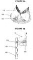
- the adjustment mechanism comprises a quick-release button locking mechanism comprising "buttons” 105 or “bumps” as a first structure in conjunction with complementary “harbors” 125 as a second structure.
- the valve member 110 may be attached to or comprise a ring 100 .
- the ring 100 includes a plurality of "buttons” 105 or “bumps” located on its outer surface at defined intervals around the circumference of the ring 100 .
- the device frame (not shown, for clarity) comprises a plurality of posts 135 attached to it on its interior surface and oriented in an axial direction, as shown in FIG. 1B .
- the plurality of posts 135 are attached to the device frame at defined intervals around the inner circumference that match up with the buttons 105 on the ring 100 .
- Each post 135 includes on an interior surface a plurality of "harbors" 125 (for example, cut-out grooves).
- the ring 100 may be locked to harbors 125 on a post 135 attached to a device frame (not shown) via the buttons 105 that comprise a quick release mechanism, allowing adjustment of the position of the valve member relative to the device frame along the longitudinal axis of the valve device, e.g., along the aortic root axis, where the aortic valve is to be replaced.
- pulling or pushing a safety catch may activate or deactivate the quick release mechanism.
- the buttons 105 are activated such that they protrude outwardly from the outer surface of the ring 100 , thereby locking into the harbors 125 of the post 135 .
- the buttons 105 are deactivated such that they retract from the harbors 125 to appear substantially even with the outer surface of the ring 100 , thereby unlocking the valve member from the device frame.
- the buttons 105 are spring loaded and activate and deactivate according to whether the spring is engaged or disengaged.
- the ring 100 may be docked in any one of several sets of harbors 125 on the plurality of posts 135 attached to the device frame, allowing adjustments along the aortic root axis.
- the harbors 125 are spaced apart by about 0.5-3 mm.
- the valve device comprises four pairs of first and second structures, however in other embodiments, the valve device may have three pairs or as many as six or eight pairs of first and second structures.
- the adjustment mechanism may comprise a controlled snap-fit locking mechanism comprising snap-fit pads 205 as a first structure in conjunction with posts 235 having complementary openings 239 as a second structure.
- the valve member 210 is attached to or comprises a ring 200 .
- the ring 200 includes several snap-fit pads 205 mounted underneath the ring 200 at defined intervals around the circumference of the ring 200 .
- the device frame (not shown, for clarity) comprises a plurality of posts 235 attached to it on its interior surface and oriented in an axial direction. The plurality of posts 235 are attached to the device frame at defined intervals around the inner circumference that match up with the snap-fit pads 205 on the ring 200 .
- Each post 235 includes a plurality of openings 239 on its interior surface and a safety slide 237 for locking a snap-fit pad 205 into an opening 239 of the post 235 .
- the openings 239 are spaced apart by about 0.5-3 mm.
- Each of the snap-fit pads 205 includes an angular head 206 for insertion into an opening 239 of a post 235 .
- the valve member 210 may be adjusted until a snap-fit pad 205 engages a desired opening 239 .
- the snap-fit pad 205 then may be locked into the opening 239 of the post 235 via the angular head 206 and the safety slide 237 .
- the snap-fit pad 205 may be spring-loaded and may be locked into an opening 239 of the post 235 after the angular head 206 of the snap-fit pad 205 engages an opening 239 , by depressing the safety slide 237 to allow it to move proximally. The new more proximal position of the safety slide 237 partially unblocks the opening 239 , thereby locking the angular head 206 of the snap-fit pad 205 into the opening 239 .
- the snap-fit pad 205 may be unlocked from an opening 239 of a post 235 by a reverse method, i.e.
- the safety slide 237 may be moved either proximally or distally to unblock the opening 239 .
- the safety slide 237 may be moved using pull wires or push-rods.
- the valve device comprises four pairs of first and second structures, however in other embodiments, the valve device may have three pairs or as many as six or eight pairs of first and second structures.
- the valve ring may be moved axially along the aortic root until a satisfactory location is achieved.
- the adjustment mechanism comprises a ratchet mechanism comprising a valve member3 10 attached to or comprising a ring 300 as a first structure in conjunction with posts having complementary ratchets - a ratchet post 335 - as a second structure.
- the device frame (not shown, for clarity) comprises a plurality of ratchet posts 335 attached to it on its interior surface and oriented in an axial direction.
- the plurality of ratchet posts 335 are attached to the device frame at defined intervals around the inner circumference.
- the ratchet posts 335 include a plurality of grooves 337. Preferably the grooves 337are spaced apart by about 0.5-3 mm.
- the grooves 337a may be angled distally (e.g., away from the aorta) or, as depicted in FIG. 3B , the grooves 337b may be angled proximally (e.g., toward the aorta).
- the grooves 337 operate to lock the ring 300, and therefore the valve member 310, at a particular position relative to the device frame.
- the ring 300 may be constricted to a relatively small radius to allow easier movement and fine tuning.
- the valve device comprises four pairs of first and second structures, however in other examples, the valve device may have three pairs or as many as six or eight pairs of first and second structures. The leaflet ring is moved axially along the aortic root until a satisfactory location is achieved.
- the adjustment mechanism comprises a snap-rivet locking mechanism comprising flexible pads 403 having at least one angular rib 404 as a first structure in conjunction with posts 435 having a plurality of complementary angular grooves 437 as a second structure.
- the valve member 410 is attached to or comprises a ring 400.
- the ring 400 includes a plurality of flexible pads 403 attached thereto. Each of the flexible pads 403 includes at least one angular rib 404 that runs perpendicular to the length of the pads.
- the device frame (not shown, for clarity) comprises a plurality of posts 435 each comprising a plurality of angular grooves 437 for interlocking with the at least one angular rib404of the flexible pads 403.
- the angular grooves 437 are spaced apart by about 0.5-3 mm.
- the plurality of posts 435 are attached to the device frame on its interior surface and oriented in an axial direction, and are attached to the device frame at defined intervals around the inner circumference that match up with the flexible pads 403 on the ring 400.
- the valve device comprises four pairs of first and second structures, however in other examples, the valve device may have three pairs or as many as six or eight pairs of first and second structures.
- the position of the valve member 410 may be adjusted by moving the ring 400 with the flexible pads 403 retracted (retracted flexible pads 403a) in the device frame axially with respect to the aortic root until a satisfactory location is achieved, as shown in FIG. 4A .
- the flexible pads 403 may then be released, as shown in FIG. 4B , in a manner to allow their angular grooves 437 to be engaged (engaged flexible pads403b) and interlocked with the angular grooves 437 of the posts 435, as shown in FIG. 4C .
- a valve assembly 510 may be loosely anchored to the support structure 520 , for example to a post of the support structure, via a flexible string 548 .
- the flexible string alternatively may be a net or a flexible wire such as a pull wire, for example.
- the flexible string 548 may be attached to the valve assembly via a first anchor 549a and may connect the valve assembly 510 to the support structure 520 by looping through the support structure.
- a free end of the flexible string may exit the proximal end of the delivery device (i.e.
- the non- anchored end of the flexible string may be connected to the delivery device.
- mechanisms within the delivery system may assist manipulation of the flexible string 548 to adjust the position of the valve assembly relative to the support structure. Such mechanisms are within the skill in the art.
- the flexible string 548 is connected to the first anchor 549a and loops around a hole or string loop (not shown) on the support structure to form a second anchor 549b to loosely suspend the valve assembly 510 .
- the flexible string 548 may be used to finely adjust the position of the valve assembly 510 relative to the support structure 520 before locking the valve assembly to the support structure using a locking mechanism.
- FIG. 6 depicts yet another embodiment of the invention in which the position of the valve member 610 may be axially and angularly fine tuned to its optimal location by pushing and pulling it along a helix rail 605 .
- the first structure is a helix rail 605 and the second structure is a roller 607 attached to the device frame 620 .
- the helix rail 605 preferably is connected to the valve member, for example a valve component, and the rollers 607 which cooperate with the helix rail 605 are attached to the device frame 620 , or support structure.
- the helix rail 605 and rollers 607 cooperate to permit rotation of the valve member 610 around a longitudinal axis and along one of the "lines" of the helix rail 605 , as illustrated. Adjustment of the valve member 610 may be accomplished by pulling or pushing it along the helix rail 605 in a manner that causes the valve member 610 to glide through the rollers 607 in the indicated directions. The valve member may be moved along the helix rail using pull wires or push-rods.
- the helix rail may be a wire, and in particular may be a shape memory wire. Where the valve device is a modular valve device, the helix rail 605 may be manufactured of a shape memory metal, for example, Nitinol and may be comprised of several interconnected segments.
- the shape memory helix rail 605 may be delivered in a delivery form that permits a small delivery profile, and then the shape memory helix rail 605 may be triggered to revert to a preconditioned helical coil shape after deployment (as shown in FIG. 6 ).
- the shape memory helix rail 605 may be delivered uncoiled or coiled so as to achieve a smaller delivery diameter than the diameter of the preset helix.
- the pitch of the preconditioned helical coil shape of the helix rail 605 may be approximately 0.5-2 mm. However, other incremental pitches suitable for the appropriate degree of fine adjustment may also be used.
- the helix rail 605 may be deployed with the valve module (for example a valve component or a series of valve sections) from the delivery system into the support structure for "automatic" subassembly and connection to the rollers 607 .
- the valve module for example a valve component or a series of valve sections
- the valve member may be axially and angularly fine tuned to its optimal location by pushing and pulling it along a helix groove (not shown).
- the helix groove may be the second structure on the device frame, and the first structure may be a plurality of complementary protrusions located on the valve member. The protrusions may be fixed or spring-loaded for engagement with the helix groove.
- first and second structures may be reversed.
- the structure designed a first structure on the valve member may be provided as a second structure on the device frame and the complementary structure designated as a second structure on the device frame may be provided as a first structure on the valve member.
- a device frame 720 or support structure which in this embodiment is illustrated as a stent, may include a post 735 as part of a 3-dimensional device frame.
- FIG. 7 illustrates how a post 735 in accordance with any of the embodiments of FIGS. 1-7 may be attached to a device frame 720 that is a stent without interfering with the expandability of the structure.
- the post 735 is sufficiently flexible to not unduly interfere with the axial flexibility of the device frame but sufficiently stiff to function as needed in the particular embodiment in which it is used.
- Posts 735 may be comprised of the same material as the device frame or a comparable material that does not chemically interact with the material of the device frame.
- the present invention encompasses substituting the post on the device frame with a groove, where appropriate.
- the adjustment mechanisms may be manufactured from metals or non-metals.
- the base of the valve member, in particular the ring structure may be made of a metal or a polymer, preferably a deformable polymer.
- the ring structure may be a self-assembly member in its preset configuration, as described in paragraphs [036]-[038] and Figs. 2a-10 of co-pending U.S. application no. 12/686,338 (self-assembly), filed on January 12, 2010.
- the adjustment mechanism of the present invention is applicable to all percutaneous prosthetic valve devices, but is particularly useful in conjunction with a modular valve devices.
- Locking mechanisms may be used to secure or attach together the device frame and valve member, provided the locking mechanism is compatible with the particular adjustment mechanism being used. Examples of locking mechanisms useful in attaching together device modules of a modular valve device are described in paragraphs [050]-[058] and Figs. 5a-6a of priority U.S. application no. 61/144,007 , in paragraphs [048]-[051], [084]-[113] and Figs. 7-15 of co-pending U.S. application no. 12/686,335 (modular), filed on January 12, 2010.
- the locking mechanisms preferably are fittings of the kind that are easily engaged from a remote location, yet also provide a secure fitting that will not disengage during use.
- the invention also may be applied to pre-assembled percutaneous valve devices. Pre-assembled valve devices are delivered to the affected vessel as one piece, and adjustment of the valve's position is not possible after implantation at the target site.
- the present invention encompasses incorporating the novel fine adjustment mechanisms into the manufacture of preassembled percutaneous valves, so that the first and second structures having complementary first and second configurations are in place on members of the pre-assembled device prior to delivery ( i.e ., outside the body).
- Examples of preassembled, percutaneous prosthetic valves into which the mechanisms of the present invention for example, in U.S. Patent Nos. 5,411,552 and 6,893,460 , and include, for example, the CoreValve RevalvingTM System from Medtronic/CoreValve Inc.
- the apparatus of the invention may be used in conjunction with the placement system and method of placing a modular device, which are described in priority U.S. application no. 61/144,007 at paragraphs [067]-[082] and Figs. 7a-8 , and co-pending US patent application no. 12/686,337 , entitled “A System and Method for Placing a Percutaneous Valve Device,” at paragraphs [024]-[042] and Figs. 1a-2 , filed on January 12, 2010.
- first and second structures having complementary configurations are: notches at various axial/angular positions along a support structure that allows a valve device to be removably reset among the various positions; hooks/clamps that allow the valve device to be anchored in different locations to a support structure; wires along a support structure that provide a track for, e.g. , eyelets on the valve module; or, any other mechanism for causing controlled position adjustment of one structure relative to another.
Landscapes
- Health & Medical Sciences (AREA)
- Cardiology (AREA)
- Engineering & Computer Science (AREA)
- Biomedical Technology (AREA)
- Life Sciences & Earth Sciences (AREA)
- Transplantation (AREA)
- Heart & Thoracic Surgery (AREA)
- Vascular Medicine (AREA)
- Oral & Maxillofacial Surgery (AREA)
- Animal Behavior & Ethology (AREA)
- General Health & Medical Sciences (AREA)
- Public Health (AREA)
- Veterinary Medicine (AREA)
- Prostheses (AREA)
- Medicines That Contain Protein Lipid Enzymes And Other Medicines (AREA)
- Medicines Containing Material From Animals Or Micro-Organisms (AREA)
Claims (6)
- Vorrichtung zum Anpassen der Position eines Ventilelements einer perkutanen Ventilvorrichtung, aufweisend:eine erste Anpassungsstruktur (105; 205; 300; 403, 405; 605), die auf dem Ventilelement (110; 210; 310; 410; 510; 610; 710) positioniert ist; undeine zweite Anpassungsstruktur (125; 239; 335, 337; 435; 437; 607), die auf einem Vorrichtungsrahmen (620; 720) positioniert ist;wobei das Ventilelement (110; 210; 310; 410; 510; 610; 710) und der Vorrichtungsrahmen (620; 720) zusammen die perkutane Ventilvorrichtung bilden, wobei die perkutane Ventilvorrichtung eine erste komprimierte Konfiguration für eine perkutane Zufuhr und eine zweite expandierte Konfiguration als eine Arbeitskonfiguration aufweist; und wobei die erste Anpassungsstruktur (105; 205; 300; 403, 405; 605) eine Konfiguration aufweist, die in komplementärer Art und Weise mit einer Konfiguration auf der zweiten Anpassungsstruktur (125; 239; 335, 337; 435, 437; 607) zusammenpasst, so dass eine Reihe von relativen Positionen zwischen dem Ventilelement (110; 210; 310; 410; 510; 610; 710) und dem Vorrichtungsrahmen (620; 720) zumindest entlang einer Längsachse der Ventilvorrichtung in der expandierten Konfiguration ermöglicht wird; undwobei die erste (105; 205; 300; 403, 405; 605) und die zweite (125; 239; 335, 337; 435, 437; 607) Struktur aus der Gruppe ausgewählt sind, die aus Folgendem besteht: Erhebungen und Vertiefungen, Schnappverschlussgliedern und Öffnungen; Spiralschienen und Rollelementen; und Spiralnuten und Vorsprüngen.
- Vorrichtung nach Anspruch 1, ferner aufweisend ein Positionsbeibehaltungsmittel.
- Vorrichtung nach Anspruch 1, wobei die Ventilvorrichtung eine modulare Ventilvorrichtung ist, wobei das Ventilelement (110; 210; 310; 410; 510; 610; 710) ein Ventilmodul ist und der Vorrichtungsrahmen (620; 720) ein Stent ist; und wobei das Ventilmodul und der Stent für eine Anordnung in der Ventilvorrichtung nach dem Einsetzen aus einer Zuführvorrichtung konfiguriert sind.
- System, aufweisend:eine perkutane Ventilvorrichtung, wobei die Ventilvorrichtung eine erste Anpassungsstruktur (105; 205; 300; 403; 605) auf einem Ventilelement (110; 210; 310; 410; 510; 610; 710) und eine zweite Anpassungsstruktur (125; 239; 335, 337; 435; 437; 607) auf einem Vorrichtungsrahmen (620; 710) aufweist, wobei das Ventilelement (110; 210; 310; 410; 510; 610; 710) und der Vorrichtungsrahmen (620; 720) zusammen die perkutane Ventilvorrichtung bilden, wobei die perkutane Ventilvorrichtung ein erste komprimierte Konfiguration für eine perkutane Zufuhr und eine zweite expandierte Konfiguration als eine Arbeitskonfiguration aufweist, wobei die erste Anpassungsstruktur (105; 205; 300; 403; 405; 605) eine Konfiguration aufweist, die mit einer Konfiguration auf der zweiten Anpassungsstruktur (125; 239; 335; 337; 435; 437; 607) in einer komplementären Art und Weise zusammenpasst, so dass eine Reihe von relativen Positionen zwischen dem Ventilelement (110; 210; 310; 410; 510; 610; 710) und dem Vorrichtungsrahmen (620; 720) zumindest entlang einer Längsachse der Ventilvorrichtung in der expandierten Konfiguration ermöglicht wird, und wobei die erste (105; 205; 300; 403; 405; 605) und die zweite (125; 239; 335; 337; 435; 437; 607) Struktur aus der Gruppe bestehend aus: Erhebungen und Vertiefungen, Schnappverschlussgliedern und Öffnungen; Spiralschienen und Rollelementen; und Spiralnuten und Vorsprüngen ausgewählt sind; undeine Zuführvorrichtung zum Zuführen und Einsetzen der Ventilvorrichtung.
- System nach Anspruch 4, ferner aufweisend ein Positionsbeibehaltungsmittel.
- System nach Anspruch 4, wobei die Ventilvorrichtung eine modulare Ventilvorrichtung ist, wobei das Ventilelement (110; 210; 310; 410; 510; 610; 710) ein Ventilmodul ist und der Vorrichtungsrahmen (620; 720) ein Stent ist; und wobei das Ventilmodul und der Stent für eine Anordnung konfiguriert sind, so dass die Ventilvorrichtung nach dem Einsetzen aus der Zuführvorrichtung ausgebildet wird.
Priority Applications (2)
| Application Number | Priority Date | Filing Date | Title |
|---|---|---|---|
| EP16164467.9A EP3061421B1 (de) | 2009-01-12 | 2010-01-13 | Vorrichtung zur feineinstellung einer perkutanen klappenstruktur |
| EP15154799.9A EP2889020B1 (de) | 2009-01-12 | 2010-01-13 | Vorrichtung zur Feineinstellung einer perkutanen Klappenstruktur |
Applications Claiming Priority (3)
| Application Number | Priority Date | Filing Date | Title |
|---|---|---|---|
| US14400709P | 2009-01-12 | 2009-01-12 | |
| US12/686,340 US8998982B2 (en) | 2009-01-12 | 2010-01-12 | Method and apparatus for fine adjustment of a percutaneous valve structure |
| PCT/IB2010/000051 WO2010079426A1 (en) | 2009-01-12 | 2010-01-13 | Method and apparatus for fine adjustment of a percutaneous valve structure |
Related Child Applications (4)
| Application Number | Title | Priority Date | Filing Date |
|---|---|---|---|
| EP16164467.9A Division EP3061421B1 (de) | 2009-01-12 | 2010-01-13 | Vorrichtung zur feineinstellung einer perkutanen klappenstruktur |
| EP16164467.9A Division-Into EP3061421B1 (de) | 2009-01-12 | 2010-01-13 | Vorrichtung zur feineinstellung einer perkutanen klappenstruktur |
| EP15154799.9A Division-Into EP2889020B1 (de) | 2009-01-12 | 2010-01-13 | Vorrichtung zur Feineinstellung einer perkutanen Klappenstruktur |
| EP15154799.9A Division EP2889020B1 (de) | 2009-01-12 | 2010-01-13 | Vorrichtung zur Feineinstellung einer perkutanen Klappenstruktur |
Publications (3)
| Publication Number | Publication Date |
|---|---|
| EP2379010A1 EP2379010A1 (de) | 2011-10-26 |
| EP2379010B1 EP2379010B1 (de) | 2015-03-25 |
| EP2379010B2 true EP2379010B2 (de) | 2018-04-04 |
Family
ID=42316293
Family Applications (3)
| Application Number | Title | Priority Date | Filing Date |
|---|---|---|---|
| EP16164467.9A Active EP3061421B1 (de) | 2009-01-12 | 2010-01-13 | Vorrichtung zur feineinstellung einer perkutanen klappenstruktur |
| EP15154799.9A Active EP2889020B1 (de) | 2009-01-12 | 2010-01-13 | Vorrichtung zur Feineinstellung einer perkutanen Klappenstruktur |
| EP10702540.5A Active EP2379010B2 (de) | 2009-01-12 | 2010-01-13 | Vorrichtung zur feineinstellung einer perkutanen klappenstruktur |
Family Applications Before (2)
| Application Number | Title | Priority Date | Filing Date |
|---|---|---|---|
| EP16164467.9A Active EP3061421B1 (de) | 2009-01-12 | 2010-01-13 | Vorrichtung zur feineinstellung einer perkutanen klappenstruktur |
| EP15154799.9A Active EP2889020B1 (de) | 2009-01-12 | 2010-01-13 | Vorrichtung zur Feineinstellung einer perkutanen Klappenstruktur |
Country Status (9)
| Country | Link |
|---|---|
| US (3) | US8998982B2 (de) |
| EP (3) | EP3061421B1 (de) |
| AU (1) | AU2010204102B2 (de) |
| CA (2) | CA2749542C (de) |
| EA (2) | EA032751B1 (de) |
| ES (3) | ES2579344T3 (de) |
| GB (1) | GB2478498B (de) |
| SE (1) | SE537303C2 (de) |
| WO (1) | WO2010079426A1 (de) |
Families Citing this family (109)
| Publication number | Priority date | Publication date | Assignee | Title |
|---|---|---|---|---|
| US9883943B2 (en) | 2006-12-05 | 2018-02-06 | Valtech Cardio, Ltd. | Implantation of repair devices in the heart |
| EP3005984B1 (de) | 2008-02-28 | 2025-10-01 | Medtronic Inc. | Herzklappenprothesensysteme |
| EP2296744B1 (de) | 2008-06-16 | 2019-07-31 | Valtech Cardio, Ltd. | Annuloplastievorrichtungen |
| US10517719B2 (en) | 2008-12-22 | 2019-12-31 | Valtech Cardio, Ltd. | Implantation of repair devices in the heart |
| US8998982B2 (en) | 2009-01-12 | 2015-04-07 | Valve Medical Ltd. | Method and apparatus for fine adjustment of a percutaneous valve structure |
| US9180007B2 (en) | 2009-10-29 | 2015-11-10 | Valtech Cardio, Ltd. | Apparatus and method for guide-wire based advancement of an adjustable implant |
| US8870950B2 (en) | 2009-12-08 | 2014-10-28 | Mitral Tech Ltd. | Rotation-based anchoring of an implant |
| US9504562B2 (en) * | 2010-01-12 | 2016-11-29 | Valve Medical Ltd. | Self-assembling modular percutaneous valve and methods of folding, assembly and delivery |
| US8795354B2 (en) * | 2010-03-05 | 2014-08-05 | Edwards Lifesciences Corporation | Low-profile heart valve and delivery system |
| US20110224785A1 (en) | 2010-03-10 | 2011-09-15 | Hacohen Gil | Prosthetic mitral valve with tissue anchors |
| US8579964B2 (en) | 2010-05-05 | 2013-11-12 | Neovasc Inc. | Transcatheter mitral valve prosthesis |
| US11653910B2 (en) | 2010-07-21 | 2023-05-23 | Cardiovalve Ltd. | Helical anchor implantation |
| US9132009B2 (en) | 2010-07-21 | 2015-09-15 | Mitraltech Ltd. | Guide wires with commissural anchors to advance a prosthetic valve |
| US9763657B2 (en) | 2010-07-21 | 2017-09-19 | Mitraltech Ltd. | Techniques for percutaneous mitral valve replacement and sealing |
| WO2012018599A1 (en) | 2010-08-03 | 2012-02-09 | Cook Medical Technologies Llc | Two valve caval stent for functional replacement of incompetent tricuspid valve |
| US9579193B2 (en) | 2010-09-23 | 2017-02-28 | Transmural Systems Llc | Methods and systems for delivering prostheses using rail techniques |
| US10321998B2 (en) | 2010-09-23 | 2019-06-18 | Transmural Systems Llc | Methods and systems for delivering prostheses using rail techniques |
| WO2012087842A1 (en) | 2010-12-23 | 2012-06-28 | The Foundry, Llc | System for mitral valve repair and replacement |
| US9308087B2 (en) | 2011-04-28 | 2016-04-12 | Neovasc Tiara Inc. | Sequentially deployed transcatheter mitral valve prosthesis |
| US9554897B2 (en) | 2011-04-28 | 2017-01-31 | Neovasc Tiara Inc. | Methods and apparatus for engaging a valve prosthesis with tissue |
| US9364326B2 (en) | 2011-06-29 | 2016-06-14 | Mitralix Ltd. | Heart valve repair devices and methods |
| US8852272B2 (en) * | 2011-08-05 | 2014-10-07 | Mitraltech Ltd. | Techniques for percutaneous mitral valve replacement and sealing |
| WO2013021374A2 (en) | 2011-08-05 | 2013-02-14 | Mitraltech Ltd. | Techniques for percutaneous mitral valve replacement and sealing |
| US20140324164A1 (en) | 2011-08-05 | 2014-10-30 | Mitraltech Ltd. | Techniques for percutaneous mitral valve replacement and sealing |
| WO2013021375A2 (en) * | 2011-08-05 | 2013-02-14 | Mitraltech Ltd. | Percutaneous mitral valve replacement and sealing |
| US9549817B2 (en) | 2011-09-22 | 2017-01-24 | Transmural Systems Llc | Devices, systems and methods for repairing lumenal systems |
| US9345573B2 (en) | 2012-05-30 | 2016-05-24 | Neovasc Tiara Inc. | Methods and apparatus for loading a prosthesis onto a delivery system |
| US9883941B2 (en) | 2012-06-19 | 2018-02-06 | Boston Scientific Scimed, Inc. | Replacement heart valve |
| EP3730066A1 (de) | 2012-10-23 | 2020-10-28 | Valtech Cardio, Ltd. | Perkutane gewebeankertechniken |
| US12053378B2 (en) | 2012-11-07 | 2024-08-06 | Transmural Systems Llc | Devices, systems and methods for repairing lumenal systems |
| US8628571B1 (en) | 2012-11-13 | 2014-01-14 | Mitraltech Ltd. | Percutaneously-deliverable mechanical valve |
| US20150351906A1 (en) | 2013-01-24 | 2015-12-10 | Mitraltech Ltd. | Ventricularly-anchored prosthetic valves |
| SG11201507947SA (en) * | 2013-03-13 | 2015-11-27 | Jenesis Surgical Llc | Articulated commissure valve stents and methods |
| CN105377191A (zh) | 2013-03-15 | 2016-03-02 | 瓣膜医学有限公司 | 用于密封经皮瓣膜的系统和方法 |
| CN103202735B (zh) * | 2013-04-01 | 2016-02-10 | 杭州启明医疗器械有限公司 | 肺动脉瓣膜置换装置及其支架 |
| US9572665B2 (en) | 2013-04-04 | 2017-02-21 | Neovasc Tiara Inc. | Methods and apparatus for delivering a prosthetic valve to a beating heart |
| US9763781B2 (en) | 2013-05-07 | 2017-09-19 | George Kramer | Inflatable transcatheter intracardiac devices and methods for treating incompetent atrioventricular valves |
| US10646333B2 (en) | 2013-10-24 | 2020-05-12 | Medtronic, Inc. | Two-piece valve prosthesis with anchor stent and valve component |
| US20170014115A1 (en) | 2014-03-27 | 2017-01-19 | Transmural Systems Llc | Devices and methods for closure of transvascular or transcameral access ports |
| US9700412B2 (en) | 2014-06-26 | 2017-07-11 | Mitralix Ltd. | Heart valve repair devices for placement in ventricle and delivery systems for implanting heart valve repair devices |
| WO2016016899A1 (en) | 2014-07-30 | 2016-02-04 | Mitraltech Ltd. | Articulatable prosthetic valve |
| US10383726B2 (en) | 2015-01-13 | 2019-08-20 | George Kramer | Implantable transcatheter intracardiac devices and methods for treating incompetent atrioventricular valves |
| CA2973940C (en) | 2015-02-05 | 2022-08-23 | Mitraltech Ltd. | Prosthetic valve with axially-sliding frames |
| US9974651B2 (en) | 2015-02-05 | 2018-05-22 | Mitral Tech Ltd. | Prosthetic valve with axially-sliding frames |
| US20160235525A1 (en) | 2015-02-12 | 2016-08-18 | Medtronic, Inc. | Integrated valve assembly and method of delivering and deploying an integrated valve assembly |
| US10034747B2 (en) | 2015-08-27 | 2018-07-31 | Medtronic Vascular, Inc. | Prosthetic valve system having a docking component and a prosthetic valve component |
| US20170056215A1 (en) | 2015-09-01 | 2017-03-02 | Medtronic, Inc. | Stent assemblies including passages to provide blood flow to coronary arteries and methods of delivering and deploying such stent assemblies |
| JP6869967B2 (ja) | 2015-09-15 | 2021-05-12 | ザ ユナイテッド ステイツ オブ アメリカ, アズ リプレゼンテッド バイ ザ セクレタリー, デパートメント オブ ヘルス アンド ヒューマン サービスThe United States Of America, As Represented By The Secretary, Department Of Health And Human Service | 経皮的グレン並びにフォンタン手術を実施するための装置及び方法 |
| WO2019046852A1 (en) | 2017-09-01 | 2019-03-07 | Nasser Rafiee | PERCUTANEOUS DERIVATION DEVICES AND ASSOCIATED METHODS |
| DE202016008737U1 (de) | 2015-12-15 | 2019-04-05 | Neovasc Tiara Inc. | Transseptales Zuführsystem |
| CN108882981B (zh) | 2016-01-29 | 2021-08-10 | 内奥瓦斯克迪亚拉公司 | 用于防止流出阻塞的假体瓣膜 |
| US10531866B2 (en) | 2016-02-16 | 2020-01-14 | Cardiovalve Ltd. | Techniques for providing a replacement valve and transseptal communication |
| US10588745B2 (en) | 2016-06-20 | 2020-03-17 | Medtronic Vascular, Inc. | Modular valve prosthesis, delivery system, and method of delivering and deploying a modular valve prosthesis |
| GB201613219D0 (en) | 2016-08-01 | 2016-09-14 | Mitraltech Ltd | Minimally-invasive delivery systems |
| USD800908S1 (en) | 2016-08-10 | 2017-10-24 | Mitraltech Ltd. | Prosthetic valve element |
| WO2018029680A1 (en) | 2016-08-10 | 2018-02-15 | Mitraltech Ltd. | Prosthetic valve with concentric frames |
| US10973631B2 (en) * | 2016-11-17 | 2021-04-13 | Edwards Lifesciences Corporation | Crimping accessory device for a prosthetic valve |
| CN109996581B (zh) | 2016-11-21 | 2021-10-15 | 内奥瓦斯克迪亚拉公司 | 用于快速收回经导管心脏瓣膜递送系统的方法和系统 |
| EP4480453A3 (de) | 2016-12-21 | 2025-01-08 | TriFlo Cardiovascular Inc. | Herzklappenstützvorrichtung und verfahren zur herstellung und verwendung davon |
| US10653523B2 (en) | 2017-01-19 | 2020-05-19 | 4C Medical Technologies, Inc. | Systems, methods and devices for delivery systems, methods and devices for implanting prosthetic heart valves |
| US10561495B2 (en) | 2017-01-24 | 2020-02-18 | 4C Medical Technologies, Inc. | Systems, methods and devices for two-step delivery and implantation of prosthetic heart valve |
| US12029647B2 (en) | 2017-03-07 | 2024-07-09 | 4C Medical Technologies, Inc. | Systems, methods and devices for prosthetic heart valve with single valve leaflet |
| US12036113B2 (en) | 2017-06-14 | 2024-07-16 | 4C Medical Technologies, Inc. | Delivery of heart chamber prosthetic valve implant |
| US10575948B2 (en) | 2017-08-03 | 2020-03-03 | Cardiovalve Ltd. | Prosthetic heart valve |
| US12064347B2 (en) | 2017-08-03 | 2024-08-20 | Cardiovalve Ltd. | Prosthetic heart valve |
| US11793633B2 (en) | 2017-08-03 | 2023-10-24 | Cardiovalve Ltd. | Prosthetic heart valve |
| US10537426B2 (en) | 2017-08-03 | 2020-01-21 | Cardiovalve Ltd. | Prosthetic heart valve |
| US11246704B2 (en) | 2017-08-03 | 2022-02-15 | Cardiovalve Ltd. | Prosthetic heart valve |
| US10888421B2 (en) | 2017-09-19 | 2021-01-12 | Cardiovalve Ltd. | Prosthetic heart valve with pouch |
| CA3073834A1 (en) | 2017-08-25 | 2019-02-28 | Neovasc Tiara Inc. | Sequentially deployed transcatheter mitral valve prosthesis |
| US10881511B2 (en) | 2017-09-19 | 2021-01-05 | Cardiovalve Ltd. | Prosthetic valve with tissue anchors configured to exert opposing clamping forces on native valve tissue |
| US12458493B2 (en) | 2017-09-19 | 2025-11-04 | Cardiovalve Ltd. | Prosthetic heart valve and delivery systems and methods |
| US9895226B1 (en) | 2017-10-19 | 2018-02-20 | Mitral Tech Ltd. | Techniques for use with prosthetic valve leaflets |
| US10722349B2 (en) * | 2017-12-07 | 2020-07-28 | Medtronic Vascular, Inc. | Adjustable prosthetic heart valve |
| GB201720803D0 (en) | 2017-12-13 | 2018-01-24 | Mitraltech Ltd | Prosthetic Valve and delivery tool therefor |
| CN111712216B (zh) | 2018-01-07 | 2024-01-26 | 苏州杰成医疗科技有限公司 | 心脏瓣膜假体和输送 |
| GB201800399D0 (en) | 2018-01-10 | 2018-02-21 | Mitraltech Ltd | Temperature-control during crimping of an implant |
| US11857441B2 (en) | 2018-09-04 | 2024-01-02 | 4C Medical Technologies, Inc. | Stent loading device |
| US10779946B2 (en) | 2018-09-17 | 2020-09-22 | Cardiovalve Ltd. | Leaflet-testing apparatus |
| US12310850B2 (en) | 2018-09-20 | 2025-05-27 | Vdyne, Inc. | Transcatheter deliverable prosthetic heart valves and methods of delivery |
| US12186187B2 (en) | 2018-09-20 | 2025-01-07 | Vdyne, Inc. | Transcatheter deliverable prosthetic heart valves and methods of delivery |
| WO2020093172A1 (en) | 2018-11-08 | 2020-05-14 | Neovasc Tiara Inc. | Ventricular deployment of a transcatheter mitral valve prosthesis |
| US11253359B2 (en) | 2018-12-20 | 2022-02-22 | Vdyne, Inc. | Proximal tab for side-delivered transcatheter heart valves and methods of delivery |
| WO2020146842A1 (en) | 2019-01-10 | 2020-07-16 | Vdyne, Llc | Anchor hook for side-delivery transcatheter heart valve prosthesis |
| US11273032B2 (en) * | 2019-01-26 | 2022-03-15 | Vdyne, Inc. | Collapsible inner flow control component for side-deliverable transcatheter heart valve prosthesis |
| GB201901887D0 (en) | 2019-02-11 | 2019-04-03 | Cardiovalve Ltd | Device for conditioning ex vivo pericardial tissue |
| US12544226B2 (en) | 2019-02-14 | 2026-02-10 | 4C Medical Technologies, Inc. | Hydrophilic skirt for paravalvular leak mitigation and fit and apposition optimization for prosthetic heart valve implants |
| EP4729034A2 (de) | 2019-03-05 | 2026-04-22 | VDyne, Inc. | Trikuspidalregurgitationssteuerungsvorrichtungen für orthogonale transkatheterherzklappenprothese |
| WO2020185597A1 (en) | 2019-03-08 | 2020-09-17 | Neovasc Tiara Inc. | Retrievable prosthesis delivery system |
| US11173027B2 (en) | 2019-03-14 | 2021-11-16 | Vdyne, Inc. | Side-deliverable transcatheter prosthetic valves and methods for delivering and anchoring the same |
| US11602429B2 (en) | 2019-04-01 | 2023-03-14 | Neovasc Tiara Inc. | Controllably deployable prosthetic valve |
| EP3952792A4 (de) | 2019-04-10 | 2023-01-04 | Neovasc Tiara Inc. | Herzklappenprothese mit natürlichem blutfluss |
| US11452628B2 (en) | 2019-04-15 | 2022-09-27 | 4C Medical Technologies, Inc. | Loading systems for collapsible prosthetic heart valve devices and methods thereof |
| AU2020267390B2 (en) | 2019-05-04 | 2025-12-04 | Vdyne, Inc. | Cinch device and method for deployment of a side-delivered prosthetic heart valve in a native annulus |
| EP3972673B1 (de) | 2019-05-20 | 2026-01-28 | Neovasc Tiara Inc. | Einführungsvorrichtung mit hämostasemechanismus |
| US10842628B1 (en) | 2019-05-22 | 2020-11-24 | TriFlo Cardiovascular Inc. | Heart valve support device |
| CN114144144B (zh) | 2019-06-20 | 2026-01-13 | 内奥瓦斯克迪亚拉公司 | 低轮廓假体二尖瓣 |
| US12133797B2 (en) | 2020-01-31 | 2024-11-05 | 4C Medical Technologies, Inc. | Prosthetic heart valve delivery system: paddle attachment feature |
| US11931253B2 (en) | 2020-01-31 | 2024-03-19 | 4C Medical Technologies, Inc. | Prosthetic heart valve delivery system: ball-slide attachment |
| US12053375B2 (en) | 2020-03-05 | 2024-08-06 | 4C Medical Technologies, Inc. | Prosthetic mitral valve with improved atrial and/or annular apposition and paravalvular leakage mitigation |
| US11992403B2 (en) | 2020-03-06 | 2024-05-28 | 4C Medical Technologies, Inc. | Devices, systems and methods for improving recapture of prosthetic heart valve device with stent frame having valve support with inwardly stent cells |
| US11707355B2 (en) | 2020-05-28 | 2023-07-25 | Medtronic, Inc. | Modular heart valve prosthesis |
| US12357459B2 (en) | 2020-12-03 | 2025-07-15 | Cardiovalve Ltd. | Transluminal delivery system |
| US20220395669A1 (en) * | 2021-01-28 | 2022-12-15 | TriFlo Cardiovascular Inc. | Delivery system for a heart valve support device |
| WO2022187560A1 (en) | 2021-03-03 | 2022-09-09 | BALCOM, Alexis | Percutaneous shunt devices and related methods |
| US12588998B1 (en) | 2022-09-01 | 2026-03-31 | 4C Medical Technologies, Inc. | Prosthetic heart valve for natural blood flow |
| EP4601585A1 (de) | 2022-10-14 | 2025-08-20 | Vdyne, Inc. | Vorrichtungen und verfahren zur freisetzung einer herzklappenprothese mit supraannularer stütze |
| WO2024151408A2 (en) * | 2023-01-09 | 2024-07-18 | Robert Leonardi | Aortic heart valve replacement devices, systems and methods |
| US20240366366A1 (en) | 2023-03-24 | 2024-11-07 | 4C Medical Technologies, Inc. | Implant delivery |
Citations (2)
| Publication number | Priority date | Publication date | Assignee | Title |
|---|---|---|---|---|
| WO2000047139A1 (en) † | 1999-02-10 | 2000-08-17 | Heartport, Inc. | Methods and devices for implanting cardiac valves |
| WO2005062980A2 (en) † | 2003-12-23 | 2005-07-14 | Sadra Medical, Inc. | Repositionable heart valve |
Family Cites Families (16)
| Publication number | Priority date | Publication date | Assignee | Title |
|---|---|---|---|---|
| AR229309A1 (es) | 1983-04-20 | 1983-07-15 | Barone Hector Daniel | Montura para valvulas cardiacas |
| DK124690D0 (da) | 1990-05-18 | 1990-05-18 | Henning Rud Andersen | Klapprotes til implantering i kroppen for erstatning af naturlig klap samt kateter til brug ved implantering af en saadan klapprotese |
| US5411552A (en) | 1990-05-18 | 1995-05-02 | Andersen; Henning R. | Valve prothesis for implantation in the body and a catheter for implanting such valve prothesis |
| US6893460B2 (en) | 2001-10-11 | 2005-05-17 | Percutaneous Valve Technologies Inc. | Implantable prosthetic valve |
| US8840663B2 (en) | 2003-12-23 | 2014-09-23 | Sadra Medical, Inc. | Repositionable heart valve method |
| US7780725B2 (en) * | 2004-06-16 | 2010-08-24 | Sadra Medical, Inc. | Everting heart valve |
| US20050137686A1 (en) | 2003-12-23 | 2005-06-23 | Sadra Medical, A Delaware Corporation | Externally expandable heart valve anchor and method |
| US7597711B2 (en) * | 2004-01-26 | 2009-10-06 | Arbor Surgical Technologies, Inc. | Heart valve assembly with slidable coupling connections |
| US20050288778A1 (en) | 2004-06-29 | 2005-12-29 | Emanuel Shaoulian | Selectively adjustable cardiac valve implants |
| US7331991B2 (en) | 2005-02-25 | 2008-02-19 | California Institute Of Technology | Implantable small percutaneous valve and methods of delivery |
| EP1883375B1 (de) * | 2005-05-24 | 2016-12-07 | Edwards Lifesciences Corporation | Prothetische herzklappe zum schnellen einsatz |
| US20070016288A1 (en) * | 2005-07-13 | 2007-01-18 | Gurskis Donnell W | Two-piece percutaneous prosthetic heart valves and methods for making and using them |
| WO2007100410A2 (en) | 2005-12-15 | 2007-09-07 | Georgia Tech Research Corporation | Systems and methods for enabling heart valve replacement |
| EP2023860A2 (de) | 2006-04-29 | 2009-02-18 | Arbor Surgical Technologies, Inc. | Mehrteilige herzklappenprothesenanordnungen sowie vorrichtung und verfahren zu ihrer einsetzung |
| WO2007130880A1 (en) | 2006-04-29 | 2007-11-15 | Arbor Surgical Technologies, Inc | Guide shields for multiple component prosthetic heart valve assemblies and apparatus and methods for using them |
| US8998982B2 (en) | 2009-01-12 | 2015-04-07 | Valve Medical Ltd. | Method and apparatus for fine adjustment of a percutaneous valve structure |
-
2010
- 2010-01-12 US US12/686,340 patent/US8998982B2/en active Active
- 2010-01-13 WO PCT/IB2010/000051 patent/WO2010079426A1/en not_active Ceased
- 2010-01-13 EP EP16164467.9A patent/EP3061421B1/de active Active
- 2010-01-13 CA CA2749542A patent/CA2749542C/en not_active Expired - Fee Related
- 2010-01-13 CA CA3015858A patent/CA3015858A1/en not_active Abandoned
- 2010-01-13 EP EP15154799.9A patent/EP2889020B1/de active Active
- 2010-01-13 SE SE1050840A patent/SE537303C2/sv not_active IP Right Cessation
- 2010-01-13 AU AU2010204102A patent/AU2010204102B2/en not_active Ceased
- 2010-01-13 ES ES15154799.9T patent/ES2579344T3/es active Active
- 2010-01-13 EA EA201591555A patent/EA032751B1/ru not_active IP Right Cessation
- 2010-01-13 EP EP10702540.5A patent/EP2379010B2/de active Active
- 2010-01-13 ES ES16164467T patent/ES2820835T3/es active Active
- 2010-01-13 EA EA201190039A patent/EA023209B1/ru not_active IP Right Cessation
- 2010-01-13 ES ES10702540.5T patent/ES2533913T5/es active Active
- 2010-01-13 GB GB1111850.2A patent/GB2478498B/en not_active Expired - Fee Related
-
2015
- 2015-03-04 US US14/638,278 patent/US9554896B2/en active Active
-
2016
- 2016-12-17 US US15/382,631 patent/US10226337B2/en active Active
Patent Citations (2)
| Publication number | Priority date | Publication date | Assignee | Title |
|---|---|---|---|---|
| WO2000047139A1 (en) † | 1999-02-10 | 2000-08-17 | Heartport, Inc. | Methods and devices for implanting cardiac valves |
| WO2005062980A2 (en) † | 2003-12-23 | 2005-07-14 | Sadra Medical, Inc. | Repositionable heart valve |
Also Published As
Similar Documents
| Publication | Publication Date | Title |
|---|---|---|
| EP2379010B1 (de) | Verfahren und vorrichtung zur feineinstellung einer perkutanen klappenstruktur | |
| US20230149158A1 (en) | Modular percutaneous valve structure and delivery method | |
| EP2379012B1 (de) | System zur platzierung einer perkutanen klappenvorrichtung | |
| AU2017204775B2 (en) | Method and apparatus for fine adjustment of a percutaneous valve structure | |
| HK1158049B (en) | Method and apparatus for fine adjustment of a percutaneous valve structure | |
| HK1207556B (en) | Apparatus for fine adjustment of a percutaneous valve structure | |
| HK1223809B (en) | Apparatus for fine adjustment of a percutaneous valve structure | |
| IE85818B1 (en) | Method and apparatus for fine adjustment of a percutaneous valve structure | |
| JP5694951B2 (ja) | 経皮弁構造体を微調節するための方法及び装置 | |
| IE85827B1 (en) | System and method for placing a percutaneous valve device | |
| HK1158051B (en) | System for placing a percutaneous valve device | |
| HK1213763B (en) | Modular percutaneous valve structure |
Legal Events
| Date | Code | Title | Description |
|---|---|---|---|
| PUAI | Public reference made under article 153(3) epc to a published international application that has entered the european phase |
Free format text: ORIGINAL CODE: 0009012 |
|
| 17P | Request for examination filed |
Effective date: 20110719 |
|
| AK | Designated contracting states |
Kind code of ref document: A1 Designated state(s): AT BE BG CH CY CZ DE DK EE ES FI FR GB GR HR HU IE IS IT LI LT LU LV MC MK MT NL NO PL PT RO SE SI SK SM TR |
|
| DAX | Request for extension of the european patent (deleted) | ||
| REG | Reference to a national code |
Ref country code: HK Ref legal event code: DE Ref document number: 1158049 Country of ref document: HK |
|
| 17Q | First examination report despatched |
Effective date: 20130205 |
|
| GRAP | Despatch of communication of intention to grant a patent |
Free format text: ORIGINAL CODE: EPIDOSNIGR1 |
|
| INTG | Intention to grant announced |
Effective date: 20141002 |
|
| GRAS | Grant fee paid |
Free format text: ORIGINAL CODE: EPIDOSNIGR3 |
|
| GRAA | (expected) grant |
Free format text: ORIGINAL CODE: 0009210 |
|
| RAP3 | Party data changed (applicant data changed or rights of an application transferred) |
Owner name: VALVE MEDICAL LTD |
|
| AK | Designated contracting states |
Kind code of ref document: B1 Designated state(s): AT BE BG CH CY CZ DE DK EE ES FI FR GB GR HR HU IE IS IT LI LT LU LV MC MK MT NL NO PL PT RO SE SI SK SM TR |
|
| REG | Reference to a national code |
Ref country code: GB Ref legal event code: FG4D |
|
| REG | Reference to a national code |
Ref country code: CH Ref legal event code: EP Ref country code: CH Ref legal event code: NV Representative=s name: P&TS SA, CH |
|
| REG | Reference to a national code |
Ref country code: ES Ref legal event code: FG2A Ref document number: 2533913 Country of ref document: ES Kind code of ref document: T3 Effective date: 20150415 |
|
| REG | Reference to a national code |
Ref country code: IE Ref legal event code: FG4D |
|
| REG | Reference to a national code |
Ref country code: DE Ref legal event code: R096 Ref document number: 602010023369 Country of ref document: DE Effective date: 20150507 |
|
| REG | Reference to a national code |
Ref country code: AT Ref legal event code: REF Ref document number: 717391 Country of ref document: AT Kind code of ref document: T Effective date: 20150515 |
|
| REG | Reference to a national code |
Ref country code: CH Ref legal event code: PCOW Free format text: NEW ADDRESS: KIRYAT ATIDIM BLDG. 8 P.O. BOX 58187, 6158101 TEL AVIV (IL) |
|
| REG | Reference to a national code |
Ref country code: SE Ref legal event code: TRGR |
|
| RAP2 | Party data changed (patent owner data changed or rights of a patent transferred) |
Owner name: VALVE MEDICAL LTD. |
|
| REG | Reference to a national code |
Ref country code: CH Ref legal event code: PCOW Free format text: NEW ADDRESS: KIRYAT ATIDIM, BUILDING 8, TEL AVIV 6158101 (IL) |
|
| REG | Reference to a national code |
Ref country code: NL Ref legal event code: T3 |
|
| REG | Reference to a national code |
Ref country code: FR Ref legal event code: RM Effective date: 20150615 |
|
| PG25 | Lapsed in a contracting state [announced via postgrant information from national office to epo] |
Ref country code: FI Free format text: LAPSE BECAUSE OF FAILURE TO SUBMIT A TRANSLATION OF THE DESCRIPTION OR TO PAY THE FEE WITHIN THE PRESCRIBED TIME-LIMIT Effective date: 20150325 Ref country code: NO Free format text: LAPSE BECAUSE OF FAILURE TO SUBMIT A TRANSLATION OF THE DESCRIPTION OR TO PAY THE FEE WITHIN THE PRESCRIBED TIME-LIMIT Effective date: 20150625 Ref country code: HR Free format text: LAPSE BECAUSE OF FAILURE TO SUBMIT A TRANSLATION OF THE DESCRIPTION OR TO PAY THE FEE WITHIN THE PRESCRIBED TIME-LIMIT Effective date: 20150325 Ref country code: LT Free format text: LAPSE BECAUSE OF FAILURE TO SUBMIT A TRANSLATION OF THE DESCRIPTION OR TO PAY THE FEE WITHIN THE PRESCRIBED TIME-LIMIT Effective date: 20150325 |
|
| REG | Reference to a national code |
Ref country code: AT Ref legal event code: MK05 Ref document number: 717391 Country of ref document: AT Kind code of ref document: T Effective date: 20150325 |
|
| REG | Reference to a national code |
Ref country code: LT Ref legal event code: MG4D |
|
| PG25 | Lapsed in a contracting state [announced via postgrant information from national office to epo] |
Ref country code: LV Free format text: LAPSE BECAUSE OF FAILURE TO SUBMIT A TRANSLATION OF THE DESCRIPTION OR TO PAY THE FEE WITHIN THE PRESCRIBED TIME-LIMIT Effective date: 20150325 Ref country code: GR Free format text: LAPSE BECAUSE OF FAILURE TO SUBMIT A TRANSLATION OF THE DESCRIPTION OR TO PAY THE FEE WITHIN THE PRESCRIBED TIME-LIMIT Effective date: 20150626 |
|
| REG | Reference to a national code |
Ref country code: DE Ref legal event code: R026 Ref document number: 602010023369 Country of ref document: DE |
|
| PLBI | Opposition filed |
Free format text: ORIGINAL CODE: 0009260 |
|
| PG25 | Lapsed in a contracting state [announced via postgrant information from national office to epo] |
Ref country code: RO Free format text: LAPSE BECAUSE OF FAILURE TO SUBMIT A TRANSLATION OF THE DESCRIPTION OR TO PAY THE FEE WITHIN THE PRESCRIBED TIME-LIMIT Effective date: 20150325 Ref country code: CZ Free format text: LAPSE BECAUSE OF FAILURE TO SUBMIT A TRANSLATION OF THE DESCRIPTION OR TO PAY THE FEE WITHIN THE PRESCRIBED TIME-LIMIT Effective date: 20150325 Ref country code: PT Free format text: LAPSE BECAUSE OF FAILURE TO SUBMIT A TRANSLATION OF THE DESCRIPTION OR TO PAY THE FEE WITHIN THE PRESCRIBED TIME-LIMIT Effective date: 20150727 Ref country code: SK Free format text: LAPSE BECAUSE OF FAILURE TO SUBMIT A TRANSLATION OF THE DESCRIPTION OR TO PAY THE FEE WITHIN THE PRESCRIBED TIME-LIMIT Effective date: 20150325 Ref country code: EE Free format text: LAPSE BECAUSE OF FAILURE TO SUBMIT A TRANSLATION OF THE DESCRIPTION OR TO PAY THE FEE WITHIN THE PRESCRIBED TIME-LIMIT Effective date: 20150325 |
|
| 26 | Opposition filed |
Opponent name: BOSTON SCIENTIFIC CORPORATION Effective date: 20151009 |
|
| PG25 | Lapsed in a contracting state [announced via postgrant information from national office to epo] |
Ref country code: IS Free format text: LAPSE BECAUSE OF FAILURE TO SUBMIT A TRANSLATION OF THE DESCRIPTION OR TO PAY THE FEE WITHIN THE PRESCRIBED TIME-LIMIT Effective date: 20150725 Ref country code: PL Free format text: LAPSE BECAUSE OF FAILURE TO SUBMIT A TRANSLATION OF THE DESCRIPTION OR TO PAY THE FEE WITHIN THE PRESCRIBED TIME-LIMIT Effective date: 20150325 Ref country code: AT Free format text: LAPSE BECAUSE OF FAILURE TO SUBMIT A TRANSLATION OF THE DESCRIPTION OR TO PAY THE FEE WITHIN THE PRESCRIBED TIME-LIMIT Effective date: 20150325 |
|
| REG | Reference to a national code |
Ref country code: FR Ref legal event code: PLFP Year of fee payment: 7 |
|
| PG25 | Lapsed in a contracting state [announced via postgrant information from national office to epo] |
Ref country code: DK Free format text: LAPSE BECAUSE OF FAILURE TO SUBMIT A TRANSLATION OF THE DESCRIPTION OR TO PAY THE FEE WITHIN THE PRESCRIBED TIME-LIMIT Effective date: 20150325 |
|
| PLAX | Notice of opposition and request to file observation + time limit sent |
Free format text: ORIGINAL CODE: EPIDOSNOBS2 |
|
| PG25 | Lapsed in a contracting state [announced via postgrant information from national office to epo] |
Ref country code: SI Free format text: LAPSE BECAUSE OF FAILURE TO SUBMIT A TRANSLATION OF THE DESCRIPTION OR TO PAY THE FEE WITHIN THE PRESCRIBED TIME-LIMIT Effective date: 20150325 |
|
| PLBB | Reply of patent proprietor to notice(s) of opposition received |
Free format text: ORIGINAL CODE: EPIDOSNOBS3 |
|
| PG25 | Lapsed in a contracting state [announced via postgrant information from national office to epo] |
Ref country code: LU Free format text: LAPSE BECAUSE OF FAILURE TO SUBMIT A TRANSLATION OF THE DESCRIPTION OR TO PAY THE FEE WITHIN THE PRESCRIBED TIME-LIMIT Effective date: 20160113 |
|
| REG | Reference to a national code |
Ref country code: HK Ref legal event code: GR Ref document number: 1158049 Country of ref document: HK |
|
| PG25 | Lapsed in a contracting state [announced via postgrant information from national office to epo] |
Ref country code: MC Free format text: LAPSE BECAUSE OF FAILURE TO SUBMIT A TRANSLATION OF THE DESCRIPTION OR TO PAY THE FEE WITHIN THE PRESCRIBED TIME-LIMIT Effective date: 20150325 |
|
| REG | Reference to a national code |
Ref country code: FR Ref legal event code: PLFP Year of fee payment: 8 |
|
| PG25 | Lapsed in a contracting state [announced via postgrant information from national office to epo] |
Ref country code: MT Free format text: LAPSE BECAUSE OF FAILURE TO SUBMIT A TRANSLATION OF THE DESCRIPTION OR TO PAY THE FEE WITHIN THE PRESCRIBED TIME-LIMIT Effective date: 20150325 |
|
| REG | Reference to a national code |
Ref country code: FR Ref legal event code: PLFP Year of fee payment: 9 |
|
| PUAH | Patent maintained in amended form |
Free format text: ORIGINAL CODE: 0009272 |
|
| STAA | Information on the status of an ep patent application or granted ep patent |
Free format text: STATUS: PATENT MAINTAINED AS AMENDED |
|
| 27A | Patent maintained in amended form |
Effective date: 20180404 |
|
| AK | Designated contracting states |
Kind code of ref document: B2 Designated state(s): AT BE BG CH CY CZ DE DK EE ES FI FR GB GR HR HU IE IS IT LI LT LU LV MC MK MT NL NO PL PT RO SE SI SK SM TR |
|
| REG | Reference to a national code |
Ref country code: DE Ref legal event code: R102 Ref document number: 602010023369 Country of ref document: DE |
|
| REG | Reference to a national code |
Ref country code: CH Ref legal event code: AELC |
|
| REG | Reference to a national code |
Ref country code: SE Ref legal event code: RPEO |
|
| REG | Reference to a national code |
Ref country code: BE Ref legal event code: FP Effective date: 20150407 |
|
| REG | Reference to a national code |
Ref country code: ES Ref legal event code: DC2A Ref document number: 2533913 Country of ref document: ES Kind code of ref document: T5 Effective date: 20180522 |
|
| PG25 | Lapsed in a contracting state [announced via postgrant information from national office to epo] |
Ref country code: HU Free format text: LAPSE BECAUSE OF FAILURE TO SUBMIT A TRANSLATION OF THE DESCRIPTION OR TO PAY THE FEE WITHIN THE PRESCRIBED TIME-LIMIT; INVALID AB INITIO Effective date: 20100113 Ref country code: SM Free format text: LAPSE BECAUSE OF FAILURE TO SUBMIT A TRANSLATION OF THE DESCRIPTION OR TO PAY THE FEE WITHIN THE PRESCRIBED TIME-LIMIT Effective date: 20150325 Ref country code: CY Free format text: LAPSE BECAUSE OF FAILURE TO SUBMIT A TRANSLATION OF THE DESCRIPTION OR TO PAY THE FEE WITHIN THE PRESCRIBED TIME-LIMIT Effective date: 20150325 |
|
| REG | Reference to a national code |
Ref country code: NL Ref legal event code: FP |
|
| PG25 | Lapsed in a contracting state [announced via postgrant information from national office to epo] |
Ref country code: MT Free format text: LAPSE BECAUSE OF FAILURE TO SUBMIT A TRANSLATION OF THE DESCRIPTION OR TO PAY THE FEE WITHIN THE PRESCRIBED TIME-LIMIT Effective date: 20160131 Ref country code: TR Free format text: LAPSE BECAUSE OF FAILURE TO SUBMIT A TRANSLATION OF THE DESCRIPTION OR TO PAY THE FEE WITHIN THE PRESCRIBED TIME-LIMIT Effective date: 20150325 Ref country code: MK Free format text: LAPSE BECAUSE OF FAILURE TO SUBMIT A TRANSLATION OF THE DESCRIPTION OR TO PAY THE FEE WITHIN THE PRESCRIBED TIME-LIMIT Effective date: 20150325 |
|
| REG | Reference to a national code |
Ref country code: HK Ref legal event code: AM43 Ref document number: 1158049 Country of ref document: HK |
|
| PG25 | Lapsed in a contracting state [announced via postgrant information from national office to epo] |
Ref country code: BG Free format text: LAPSE BECAUSE OF FAILURE TO SUBMIT A TRANSLATION OF THE DESCRIPTION OR TO PAY THE FEE WITHIN THE PRESCRIBED TIME-LIMIT Effective date: 20150325 |
|
| PGFP | Annual fee paid to national office [announced via postgrant information from national office to epo] |
Ref country code: SE Payment date: 20190129 Year of fee payment: 10 Ref country code: BE Payment date: 20190128 Year of fee payment: 10 |
|
| REG | Reference to a national code |
Ref country code: DE Ref legal event code: R119 Ref document number: 602010023369 Country of ref document: DE |
|
| REG | Reference to a national code |
Ref country code: CH Ref legal event code: PL |
|
| REG | Reference to a national code |
Ref country code: SE Ref legal event code: EUG |
|
| REG | Reference to a national code |
Ref country code: SE Ref legal event code: EUG |
|
| REG | Reference to a national code |
Ref country code: BE Ref legal event code: MM Effective date: 20200131 |
|
| PG25 | Lapsed in a contracting state [announced via postgrant information from national office to epo] |
Ref country code: SE Free format text: LAPSE BECAUSE OF NON-PAYMENT OF DUE FEES Effective date: 20200114 Ref country code: DE Free format text: LAPSE BECAUSE OF NON-PAYMENT OF DUE FEES Effective date: 20200801 |
|
| PG25 | Lapsed in a contracting state [announced via postgrant information from national office to epo] |
Ref country code: CH Free format text: LAPSE BECAUSE OF NON-PAYMENT OF DUE FEES Effective date: 20200131 Ref country code: BE Free format text: LAPSE BECAUSE OF NON-PAYMENT OF DUE FEES Effective date: 20200131 Ref country code: LI Free format text: LAPSE BECAUSE OF NON-PAYMENT OF DUE FEES Effective date: 20200131 |
|
| P01 | Opt-out of the competence of the unified patent court (upc) registered |
Effective date: 20230510 |
|
| PGFP | Annual fee paid to national office [announced via postgrant information from national office to epo] |
Ref country code: NL Payment date: 20260126 Year of fee payment: 17 |
|
| PGFP | Annual fee paid to national office [announced via postgrant information from national office to epo] |
Ref country code: GB Payment date: 20260127 Year of fee payment: 17 |
|
| PGFP | Annual fee paid to national office [announced via postgrant information from national office to epo] |
Ref country code: ES Payment date: 20260202 Year of fee payment: 17 |
|
| PGFP | Annual fee paid to national office [announced via postgrant information from national office to epo] |
Ref country code: IE Payment date: 20260127 Year of fee payment: 17 |
|
| PGFP | Annual fee paid to national office [announced via postgrant information from national office to epo] |
Ref country code: IT Payment date: 20260121 Year of fee payment: 17 |
|
| PGFP | Annual fee paid to national office [announced via postgrant information from national office to epo] |
Ref country code: FR Payment date: 20260126 Year of fee payment: 17 |