EP2378331A1 - Verfahren zur montage optischer konnektoren - Google Patents
Verfahren zur montage optischer konnektoren Download PDFInfo
- Publication number
- EP2378331A1 EP2378331A1 EP10826766A EP10826766A EP2378331A1 EP 2378331 A1 EP2378331 A1 EP 2378331A1 EP 10826766 A EP10826766 A EP 10826766A EP 10826766 A EP10826766 A EP 10826766A EP 2378331 A1 EP2378331 A1 EP 2378331A1
- Authority
- EP
- European Patent Office
- Prior art keywords
- fiber
- optical connector
- ferrule
- housing
- rear housing
- Prior art date
- Legal status (The legal status is an assumption and is not a legal conclusion. Google has not performed a legal analysis and makes no representation as to the accuracy of the status listed.)
- Granted
Links
- 230000003287 optical effect Effects 0.000 title claims abstract description 99
- 238000000034 method Methods 0.000 title claims abstract description 34
- 239000000835 fiber Substances 0.000 claims abstract description 52
- 239000013307 optical fiber Substances 0.000 claims abstract description 40
- 238000007526 fusion splicing Methods 0.000 claims description 4
- 239000000428 dust Substances 0.000 abstract description 44
- 230000004927 fusion Effects 0.000 abstract description 23
- 230000002787 reinforcement Effects 0.000 description 8
- 238000003780 insertion Methods 0.000 description 6
- 230000037431 insertion Effects 0.000 description 6
- 230000003014 reinforcing effect Effects 0.000 description 3
- 229920000271 Kevlar® Polymers 0.000 description 1
- 239000011248 coating agent Substances 0.000 description 1
- 238000000576 coating method Methods 0.000 description 1
- 230000000694 effects Effects 0.000 description 1
- 229920006015 heat resistant resin Polymers 0.000 description 1
- 239000004761 kevlar Substances 0.000 description 1
- 239000000155 melt Substances 0.000 description 1
- 239000004033 plastic Substances 0.000 description 1
- 229920005989 resin Polymers 0.000 description 1
- 239000011347 resin Substances 0.000 description 1
Images


Classifications
-
- G—PHYSICS
- G02—OPTICS
- G02B—OPTICAL ELEMENTS, SYSTEMS OR APPARATUS
- G02B6/00—Light guides; Structural details of arrangements comprising light guides and other optical elements, e.g. couplings
- G02B6/24—Coupling light guides
- G02B6/36—Mechanical coupling means
- G02B6/38—Mechanical coupling means having fibre to fibre mating means
- G02B6/3807—Dismountable connectors, i.e. comprising plugs
- G02B6/3833—Details of mounting fibres in ferrules; Assembly methods; Manufacture
- G02B6/3846—Details of mounting fibres in ferrules; Assembly methods; Manufacture with fibre stubs
-
- G—PHYSICS
- G02—OPTICS
- G02B—OPTICAL ELEMENTS, SYSTEMS OR APPARATUS
- G02B6/00—Light guides; Structural details of arrangements comprising light guides and other optical elements, e.g. couplings
- G02B6/24—Coupling light guides
- G02B6/36—Mechanical coupling means
- G02B6/38—Mechanical coupling means having fibre to fibre mating means
- G02B6/3807—Dismountable connectors, i.e. comprising plugs
- G02B6/3833—Details of mounting fibres in ferrules; Assembly methods; Manufacture
- G02B6/3847—Details of mounting fibres in ferrules; Assembly methods; Manufacture with means preventing fibre end damage, e.g. recessed fibre surfaces
- G02B6/3849—Details of mounting fibres in ferrules; Assembly methods; Manufacture with means preventing fibre end damage, e.g. recessed fibre surfaces using mechanical protective elements, e.g. caps, hoods, sealing membranes
-
- G—PHYSICS
- G02—OPTICS
- G02B—OPTICAL ELEMENTS, SYSTEMS OR APPARATUS
- G02B6/00—Light guides; Structural details of arrangements comprising light guides and other optical elements, e.g. couplings
- G02B6/24—Coupling light guides
- G02B6/36—Mechanical coupling means
- G02B6/38—Mechanical coupling means having fibre to fibre mating means
- G02B6/3807—Dismountable connectors, i.e. comprising plugs
- G02B6/381—Dismountable connectors, i.e. comprising plugs of the ferrule type, e.g. fibre ends embedded in ferrules, connecting a pair of fibres
- G02B6/3818—Dismountable connectors, i.e. comprising plugs of the ferrule type, e.g. fibre ends embedded in ferrules, connecting a pair of fibres of a low-reflection-loss type
- G02B6/3821—Dismountable connectors, i.e. comprising plugs of the ferrule type, e.g. fibre ends embedded in ferrules, connecting a pair of fibres of a low-reflection-loss type with axial spring biasing or loading means
-
- G—PHYSICS
- G02—OPTICS
- G02B—OPTICAL ELEMENTS, SYSTEMS OR APPARATUS
- G02B6/00—Light guides; Structural details of arrangements comprising light guides and other optical elements, e.g. couplings
- G02B6/24—Coupling light guides
- G02B6/36—Mechanical coupling means
- G02B6/38—Mechanical coupling means having fibre to fibre mating means
- G02B6/3807—Dismountable connectors, i.e. comprising plugs
- G02B6/389—Dismountable connectors, i.e. comprising plugs characterised by the method of fastening connecting plugs and sockets, e.g. screw- or nut-lock, snap-in, bayonet type
- G02B6/3893—Push-pull type, e.g. snap-in, push-on
Definitions
- the present invention relates to a method for assembling an optical connector equipped with a ferrule member holding a built-in fiber.
- Patent Literature 1 As a conventional optical connector assembling method, one disclosed in Patent Literature 1 has been known, for example.
- the optical connector assembling method disclosed in Patent Literature 1 is one in which, while an optical cord is passed through a rear housing and a protection sleeve, a coated optical fiber exposed by removing an outer jacket of a leading end portion of the optical cord and a short optical fiber held by a connector ferrule are fusion-spliced to each other, the fusion-spliced part is covered with the protection sleeve, and then a plug frame and the rear housing are joined to each other, so as to be integrated with each other.
- Patent Literature 2 discloses that, while a holding part of a ferrule holder (protection cap) is fitted onto a tubular part of a ferrule, a built-in optical fiber held by the ferrule and a coated optical fiber to be connected thereto are fusion-spliced to each other.
- the protection cap After performing fusion splicing while mounting a protection cap to a ferrule as disclosed in the above-mentioned Patent Literature 2, the protection cap has conventionally been removed from the ferrule at the time of joining the plug frame to the rear housing. However, carelessly removing the protection cap from the ferrule may pull and twist the coated optical fiber, thereby breaking the latter. This makes it hard to remove the ferrule from the protection cap, thereby worsening workability.
- the present invention provides a method for assembling an optical connector comprising a ferrule member having a ferrule body holding a built-in fiber, a first housing for accommodating the ferrule member, and a second housing for introducing therein an optical fiber to be connected to the built-in fiber; the method comprising the steps of mounting a protection cap to the ferrule body, fusion-splicing the optical fiber introduced in the second housing and the built-in fiber to each other, and inserting the protection cap mounted with the ferrule body into the first housing, so as to assemble the first and second housings to each other.
- the optical connector assembling method in accordance with the present invention while the ferrule body of the ferrule member is mounted with the protection cap, the optical fiber introduced in the second housing and the built-in fiber held by the ferrule body are fusion-spliced to each other. Thereafter, while the protection cap is mounted to the ferrule body without being removed therefrom, the first and second housings are assembled to each other, so as to construct the optical connector. This eliminates the time and effort to remove the protection cap from the ferrule body so as not to pull or twist the optical fiber, thereby making it possible to prevent workability from worsening.
- the protection cap has a handle provided at a leading end thereof, while the method further comprises the step of cutting the handle off after performing the step of assembling the first and second housings to each other.
- the protection cap having a leading end provided with the handle makes it easier for the protection cap mounted with the ferrule body to carry and treat when fusion-splicing the optical fiber and the built-in fiber to each other. After assembling the first and second housings to each other, the handle of the protection cap becomes unnecessary and thus is preferably cut off.
- the present invention can prevent workability from worsening.
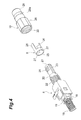
- Fig. 1 is a perspective view illustrating an optical connector assembled by one embodiment of the optical connector assembling method in accordance with the present invention.
- Fig. 2 is an exploded perspective view of the optical connector illustrated in Fig. 1(a)
- Fig. 3 is a sectional view of the optical connector illustrated in Fig. 1(a) .
- the optical connector 1 of this embodiment is a cord type LC connector having an optical cord 2 assembled thereto.
- the optical cord 2 has a coated optical fiber 3, an outer jacket 4 covering the coated optical fiber 3, and a tensile-resistant fiber (Kevlar) 5 having a very small diameter interposed between the coated optical fiber 3 and outer jacket 4.
- the tensile-resistant fiber 5 is incorporated in the optical cord 2 while being assembled into a bundle (see Fig. 5 ).
- the optical connector 1 comprises a ferrule member 6, a plug housing 7 accommodating the ferrule member 6, a rear housing 8 joined to a rear end part of the plug housing 7, an outer jacket holding member 9 and a securing member 10 which are mounted to the rear housing 8, and a boot 11 attached to the securing member 10.
- the ferrule member 6 has a ferrule body 13 holding a short built-in fiber 12 and a flange 14 secured to the ferrule body 13.
- the built-in fiber 12 extends by a predetermined length rearward from the ferrule member 6.
- the leading end of the coated optical fiber 3 exposed by removing the outer jacket 4 from a leading end portion of the optical cord 2 is fusion-spliced to the leading end of the built-in fiber 12.
- fusion-spliced part S between the built-in fiber 12 and the coated optical fiber 3 is protected by a fusion protection sleeve 15.
- the ferrule body 13 is covered with a dust cap (protection cap) 16 for protecting the ferrule body 13 against dust, dirt, and the like (see Fig. 1(a) ).
- the dust cap 16 has a substantially cylindrical form.
- the dust cap 16 is formed from a heat-resistant plastic which neither melts nor softens at a high temperature of 200°C.
- An antislip corrugation 16b is provided on the outer circumferential face in the front-side portion of the dust cap 16.
- the plug housing 7 is formed with an insertion hole 17 extending longitudinally therethrough.
- the insertion hole 17 has a size larger than the outer diameter of the dust cap 16 such that the dust cap 16 can pass therethrough.
- the insertion hole 17 has a circular cross section with a diameter slightly larger than the outer diameter of the dust cap 16.
- the front end part of the rear housing 8 is provided with four support projections 19 which support a spring 18 for urging the ferrule member 6 forward.
- the spring 18 is disposed in the insertion hole 17 of the plug housing 7. Providing thus configured spring 18 enables PC (Physical Contact) connection with the opposite optical connector.
- the support projections 19 project forward from the rear housing 8 and are disposed at equally spaced intervals in the circumferential direction thereof.
- the spring 18 comes into contact with the inner walls of two opposing support projections 19 in the four support projections 19, for example, and thus is held easily and reliably by the front end part of the rear housing 8.
- the number of the support projections 19 is not limited to 4 in particular as long as they support the spring 18 at a plurality of locations.
- the rear housing 8 has a larger tubular part 20 and a smaller tubular part 21 disposed on the rear side of the larger tubular part 20.
- the diameter of the smaller tubular part 21 is smaller than that of the larger tubular part 20.
- the outer circumferential face of the larger tubular part 20 is formed with a male thread 22.
- a pair of guide rails 23 for guiding the outer jacket holding member 9 are formed such as to extend longitudinally.
- a pair of blades 24 for securing the outer jacket 4 of the optical cord 2 are also formed on the outer circumferential face of the smaller tubular part 21.
- the above-mentioned outer jacket holding member 9 and securing member 10 are mounted to thus constructed rear housing 8.
- the outer jacket holding member 9 has an annular part 25 adapted to fit onto the smaller tubular part 21 and a pair of holding arms 26 which are integrated with the annular part 25 and extend axially of the annular part 25.
- the inner circumferential face of the annular part 25 is formed with a pair of protrusions 27 adapted to engage the respective guide rails 23 of the smaller tubular part 21.
- the securing member 10 has a substantially tubular form.
- the securing member 10 has a tensile-resistant fiber securing part 28 for securing the tensile-resistant fiber 5 (see Fig. 5 ) to the larger tubular part 20 of the rear housing 8 and an outer jacket securing part 29, provided on the rear side of the tensile-resistant fiber securing part 28, for securing the outer jacket 4 of the optical cord 2 to the smaller tubular part 21 of the rear housing 8 through the holding arms 26.
- the inner circumferential face of the tensile-resistant fiber securing part 28 is formed with a female thread 30 adapted to mate with the male thread 22 of the larger tubular part 20.
- a predetermined clearance is provided between the male thread 22 and the female thread 30 so that the larger tubular part 20 and the tensile-resistant fiber securing part 28 can hold the tensile-resistant fiber 5 therebetween.
- the outer jacket securing part 29 has a tapered region 29a which tapers down to the rear side of the securing member 10. Therefore, the opening diameter at the rear end of the securing member 10 is smaller than that at the front end of the securing member 10. Specifically, the opening diameter at the rear end of the securing member 10 is smaller than the outer diameter of the outer jacket holding member 9.
- the above-mentioned boot 11 is mounted to the outer jacket securing part 29.
- the boot 11 protects the optical cord 2 such that no drastic bend acts on the optical cord 2 behind the rear housing 8.
- a reinforcement tube 31 has been attached to the boot 1 beforehand.
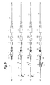
- the outer jacket 4 is removed from the leading end portion of the optical cord 2, so as to expose the coated optical fiber 3 and the tensile-resistant fiber 5. Then, an unnecessary part of the tensile-resistant fiber 5 is cut off. Subsequently, as illustrated in Fig. 5(c) , the leading end portion of the outer jacket 4 is torn into a bifurcated form. Thereafter, as illustrated in Fig. 5(d) , the bifurcated outer jacket 4 and the tensile-resistant fiber 5 are turned over.
- the coated optical fiber 3 is passed through the fusion protection sleeve 15. Then, as illustrated in Fig. 6(b) , the coating is removed from a leading end portion of the coated optical fiber 3, so as to expose and clean a bare fiber 3a. Subsequently, as illustrated in Fig. 6(c) , a leading end portion of the optical cord 2 is set in a fusion fiber holder 32. Then, as illustrated in Fig. 6(d) , a leading end part of the bare fiber 3 a is cut off. Thereafter, the fusion fiber holder 32 is set in a fusion splicer (not depicted).
- a handled dust cap 16A is prepared.
- the handled dust cap 16A is one in which a rod-shaped handle 16a is integrally attached to the leading end of the dust cap 16.
- a spherical terminal part 16c is disposed at a leading end part of the handle 16a. Providing thus configured terminal part 16c makes it possible to recognize the leading end part of the handle 16a by touching.
- the terminal part 16c may also be shaped like a strip or crank.
- the handled dust cap 16A is mounted to the ferrule body 13 of the ferrule member 6 holding the built-in fiber 12. Then, as illustrated in Fig. 7(c) , the ferrule member 6 having the handled dust cap 16A attached thereto is set in a ferrule holder 33.
- holding the handle 16a of the handled dust cap 16A with one hand makes it easier to carry and set in the ferrule holder 33.
- the ferrule holder 33 is set in the fusion splicer (not depicted).
- the fusion splicer fusion-splices the leading end of the built-in fiber 12 and the leading end of the bare fiber 3a of the coated optical fiber 3 to each other.
- the fusion protection sleeve 15 is moved to the position of the fusion-spliced part S between the built-in fiber 12 and the coated optical fiber 3 and heat-shrunk at a temperature of about 200°C in this state. This keeps the fusion protection sleeve 15 from shifting from the position of the fusion-spliced part S. Then, as illustrated in Fig. 8(c) , the turned-over outer jacket 4 and tensile-resistant fiber 5 are returned to their initial state.
- the plug housing 7 is prepared. Subsequently, as illustrated in Fig. 9(b) , the handled dust cap 16A is passed through the plug housing 7, so as to assemble the plug housing 7 to the rear housing 8. Then, as illustrated in Fig. 9(c) , while the bifurcated outer jacket 4 is mounted on the blades 24 of the smaller tubular part 21 of the rear housing 8, the outer jacket holding member 9 is fitted onto the smaller tubular part 21. As a consequence, the blades 24 bite into the outer jacket 4.
- the securing member 10 is screwed onto the larger tubular part 20 as illustrated in Fig. 10(a) .
- the tensile-resistant fiber 5 is held between the larger tubular part 20 and the tensile-resistant fiber securing part 28, so as to be secured.
- the smaller tubular part 21 of the rear housing 8 is covered with the outer jacket securing part 29 of the securing member 10. Since the outer jacket securing part 29 has the tapered region 29a tapering down to the rear side of the securing member 10, each of the holding arms 26 of the outer jacket holding member 9 is pressed by the outer jacket securing part 29, so as to bend toward the smaller tubular part 21. As a consequence, the bifurcated outer jacket 4 is held between the outer jacket securing part 29 and the smaller tubular part 21 through the holding arms 26, so as to be secured firmly.
- the boot 11 having the reinforcement tube 31 attached thereto is mounted to the outer jacket securing part 29 of the securing member 10.
- the handle 16a is cut off from the handled dust cap 16A with fingers. The foregoing completes the optical connector 1 illustrated in Fig. 1(a) .
- the ferrule member 6 and the handled dust cap 16A are also exposed to a high temperature of about 200°C.
- the handled dust cap 16A is formed from a heat-resistant resin as mentioned above and thus may slide out of the ferrule body 13 when the resin softens or thermally expands. For preventing this from occurring, the securing force of the handled dust cap 16A against the ferrule body 13 is typically made stronger.
- the handled dust cap 16A is harder to remove from the ferrule member 6.
- holding the fusion protection sleeve 15 with one hand and strongly pulling or twisting the handled dust cap 16A with the other hand may break the coated optical fiber 3 within the fusion protection sleeve 15.
- this operation is difficult, since the flange 14 is very small.
- the insertion hole 17 of the plug housing 7 has such a size as to allow the handled dust cap 16A to pass therethrough, so that the plug housing 7 is assembled to the rear housing 8 while the ferrule body 13 keeps the handled dust cap 16A mounted thereto, whereby it is not necessary for the handled dust cap 16A to be removed from the ferrule body 13 during the operation of assembling the optical connector 1.
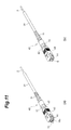
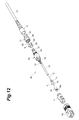
- Fig. 11 is a perspective view illustrating another optical connector assembled by one embodiment of the optical connector assembling method in accordance with the present invention.
- Fig. 12 is an exploded perspective view of the optical connector illustrated in Fig. 11(a)
- Fig. 13 is a sectional view of the optical connector illustrated in Fig. 11(a) .
- the optical connector 40 is a cord type LC connector having the optical cord 2 assembled thereto.
- the optical connector 40 comprises a plug housing 41 and a rear housing 42 in place of the plug housing 7 and rear housing 8 in the above-mentioned embodiment.
- the inner structure of the plug housing 41 is substantially the same as that of the above-mentioned plug housing 7.
- the rear housing 42 has the four support projections, larger tubular part 20, and smaller tubular part 21.
- the optical connector 40 further comprises a grip 43 covering the plug housing 41 and rear housing 42.
- the handled dust cap 16A is passed through the plug housing 41, so as to assemble the plug housing 41 to the rear housing 42.
- the outer jacket 4 and tensile-resistant fiber 5 (not depicted) of the cord 2 are secured to the rear housing 42 by the outer jacket holding member 9 and the securing member 10, and the boot 11 is mounted to the securing member 10 as in the above-mentioned embodiment.
- the grip 43 is assembled to the plug housing 41 and rear housing 42, and then the handle 16a of the handled dust cap 16A is cut off with fingers. The foregoing completes the optical connector 40 illustrated in Fig. 11(a) .
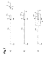
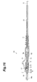
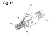
- Fig. 15 is a perspective view illustrating still another optical connector assembled by one embodiment of the optical connector assembling method in accordance with the present invention.
- Fig. 16 is a sectional view of the optical connector illustrated in Fig. 15(a) .
- the optical connector 50 is a coated fiber type LC connector having the coated optical fiber 3 assembled thereto.
- the optical connector 50 comprises a rear housing 51 in place of the rear housing 8 in the above-mentioned embodiment.
- the optical connector 50 lacks the outer jacket holding member 9 and securing member 10 in the above-mentioned embodiment.
- a front end part of the rear housing 51 is provided with four support projections 19 supporting the spring 18 as in the above-mentioned rear housing 8.
- a tubular part 52 is disposed on the rear side of the rear housing 51.
- the boot 11 having the reinforcement tube 31 attached thereto is mounted to the tubular part 52.
- the fusion protection sleeve 15, the rear housing 51 having the spring 18 attached thereto, and the boot 11 having the reinforcement tube 31 attached thereto are arranged in this order from the front side, and the coated optical fiber 3 is inserted into these components from their rear side as illustrated in Fig. 18(a) .
- the handled dust cap 16A is mounted to the ferrule body 13 of the ferrule member 6, and the built-in fiber 12 held by the ferrule member 6 and the coated optical fiber 3 are fusion-spliced to each other as in the above-mentioned embodiment.
- the fusion protection sleeve 15 is moved to the position of the fusion-spliced part S between the built-in fiber 12 and the coated optical fiber 3 and heat-shrunk in this state.
- the plug housing 7 is prepared.
- the handled dust cap 16A is passed through the plug housing 7, so as to assemble the plug housing 7 to the rear housing 51.
- the handle of the handled dust cap 16A is cut off with fingers. The foregoing completes the optical connector 50 illustrated in Fig. 15(a) .
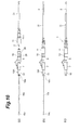
- Fig. 20 is a perspective view illustrating still another optical connector assembled by one embodiment of the optical connector assembling method in accordance with the present invention.
- Fig. 21 is a sectional view of the optical connector illustrated in Fig. 20(a) .
- the optical connector 60 is a coated fiber type SC connector having the coated optical fiber 3 assembled thereto.
- the optical connector 60 comprises a rear housing 61 in place of the rear housing 42 in the above-mentioned embodiment.
- the optical connector 60 lacks the outer jacket holding member 9 and securing member 10 in the above-mentioned embodiment.
- a front end part of the rear housing 61 is provided with four support projections 19 supporting the spring 18.
- a tubular part 62, to which the boot 11 is mounted, is disposed on the rear side of the rear housing 61.
- the handled dust cap 16A is mounted to the ferrule body 13 of the ferrule member 6, and the coated optical fiber 3 is passed through the fusion protection sleeve 15, the rear housing 61 having the spring 18 attached thereto, and the boot 11 having the reinforcement tube 31 attached thereto from their rear side as illustrated in Fig. 22(a) .
- the built-in fiber 12 held by the ferrule member 6 and the coated optical fiber 3 of the optical cord 2 are fusion-spliced to each other, and the fusion-spliced part S between the built-in fiber 12 and the coated optical fiber 3 of the optical cord 2 is reinforced by the fusion protection sleeve 15 as in the above-mentioned embodiment.
- the handled dust cap 16A is passed through the plug housing 41, so as to assemble the plug housing 41 to the rear housing 61.
- the grip 43 is assembled to the plug housing 41 and rear housing 61, and thereafter the handle 16a is cut off from the handled dust cap 16A with fingers.
- the foregoing completes the optical connector 60 illustrated in Fig. 20(a) .
Landscapes
- Physics & Mathematics (AREA)
- General Physics & Mathematics (AREA)
- Optics & Photonics (AREA)
- Mechanical Coupling Of Light Guides (AREA)
Applications Claiming Priority (2)
| Application Number | Priority Date | Filing Date | Title |
|---|---|---|---|
| JP2009248028A JP5144623B2 (ja) | 2009-10-28 | 2009-10-28 | 光コネクタの組立方法 |
| PCT/JP2010/069062 WO2011052634A1 (ja) | 2009-10-28 | 2010-10-27 | 光コネクタの組立方法 |
Publications (3)
| Publication Number | Publication Date |
|---|---|
| EP2378331A1 true EP2378331A1 (de) | 2011-10-19 |
| EP2378331A4 EP2378331A4 (de) | 2014-11-05 |
| EP2378331B1 EP2378331B1 (de) | 2019-05-08 |
Family
ID=43922059
Family Applications (1)
| Application Number | Title | Priority Date | Filing Date |
|---|---|---|---|
| EP10826766.7A Active EP2378331B1 (de) | 2009-10-28 | 2010-10-27 | Verfahren zur montage optischer konnektoren |
Country Status (10)
| Country | Link |
|---|---|
| US (1) | US8539796B2 (de) |
| EP (1) | EP2378331B1 (de) |
| JP (1) | JP5144623B2 (de) |
| KR (1) | KR101252392B1 (de) |
| CN (1) | CN102282493B (de) |
| BR (1) | BRPI1007248B1 (de) |
| ES (1) | ES2734521T3 (de) |
| MX (1) | MX2011007656A (de) |
| PT (1) | PT2378331T (de) |
| WO (1) | WO2011052634A1 (de) |
Cited By (2)
| Publication number | Priority date | Publication date | Assignee | Title |
|---|---|---|---|---|
| CN102928922A (zh) * | 2012-11-01 | 2013-02-13 | 南京普天天纪楼宇智能有限公司 | 一种热熔型光纤快速连接器 |
| CN107920716A (zh) * | 2015-07-10 | 2018-04-17 | 奥林巴斯株式会社 | 形状检测插入装置 |
Families Citing this family (9)
| Publication number | Priority date | Publication date | Assignee | Title |
|---|---|---|---|---|
| ES2703235T3 (es) | 2011-11-23 | 2019-03-07 | Adc Telecommunications Inc | Conector de fibra óptica multi-fibra |
| CN104364686B (zh) | 2012-02-07 | 2016-11-16 | 泰科电子瑞侃有限公司 | 用于连接器的线缆端接组件和方法 |
| SG11201405020TA (en) * | 2012-02-20 | 2014-09-26 | Adc Telecommunications Inc | Fiber optic connector, fiber optic connector and cable assembly, and methods for manufacturing |
| US8939654B2 (en) | 2012-09-27 | 2015-01-27 | Adc Telecommunications, Inc. | Ruggedized multi-fiber fiber optic connector with sealed dust cap |
| US9720185B2 (en) | 2014-05-23 | 2017-08-01 | Commscope Technologies Llc | Systems and method for processing optical cable assemblies |
| KR101625146B1 (ko) * | 2014-09-26 | 2016-05-30 | 네트워크케이블 주식회사 | 광 케이블 및 그 설치방법 |
| CN107193091B (zh) | 2016-03-14 | 2020-09-04 | 康普科技有限责任公司 | 强化的阴光纤连接器光缆组件 |
| CN107153239A (zh) * | 2017-06-07 | 2017-09-12 | 江苏法尔胜光电科技有限公司 | 一种制作传能光缆的组装注胶一体化装置 |
| JP7161314B2 (ja) * | 2018-06-01 | 2022-10-26 | 古河電気工業株式会社 | 光コネクタおよび光コネクタの組立方法 |
Citations (2)
| Publication number | Priority date | Publication date | Assignee | Title |
|---|---|---|---|---|
| US20080181563A1 (en) * | 2007-01-31 | 2008-07-31 | The Furukawa Electric Co., Ltd. | Ferrule transfer method and ferrule holder |
| WO2009011799A1 (en) * | 2007-07-16 | 2009-01-22 | Corning Cable Systems Llc | Fusion-splice fiber optic connectors and related tools |
Family Cites Families (17)
| Publication number | Priority date | Publication date | Assignee | Title |
|---|---|---|---|---|
| JP2716390B2 (ja) * | 1995-02-10 | 1998-02-18 | 日本電気エンジニアリング株式会社 | 光ファイバコネクタフェルール |
| US5748819A (en) * | 1995-04-05 | 1998-05-05 | Siecor Corporation | Field installable optical fiber connector and an associated method of fabrication |
| US5764837A (en) * | 1995-07-14 | 1998-06-09 | Cogent Light Technologies, Inc. | Snap-in proximal connector for mounting an optic fiber element into a light source system |
| US6227717B1 (en) * | 1997-12-16 | 2001-05-08 | The Siemon Company | Dust caps for use with telecommunications adapters and connectors |
| EP0939327A3 (de) * | 1998-02-27 | 2002-02-13 | Siemens Aktiengesellschaft | Steckeranschluss für Lichtwellenleiter und Verfahren zu dessen Herstellung |
| US6188825B1 (en) * | 1999-04-15 | 2001-02-13 | Lucent Technologies, Inc. | Dust cover for protecting optical fiber sleeve housing |
| WO2000073830A1 (en) | 1999-06-01 | 2000-12-07 | Nippon Telegraph And Telephone Corporation | Optical plug connector, method of manufacture and assembly tool |
| JP2001013373A (ja) * | 1999-06-28 | 2001-01-19 | Seiko Instruments Inc | 保護キャップ |
| US6626582B2 (en) * | 2000-02-17 | 2003-09-30 | Cogent Light Technologies, Inc. | Snap-on connector system for coupling light from an illuminator to a fiber optic |
| US7198409B2 (en) * | 2003-06-30 | 2007-04-03 | Adc Telecommunications, Inc. | Fiber optic connector holder and method |
| US7583883B2 (en) | 2005-07-26 | 2009-09-01 | Adc Telecommunications, Inc. | Fiber optic connector holder |
| JP4495175B2 (ja) | 2006-03-20 | 2010-06-30 | 古河電気工業株式会社 | フェルールの搬送方法およびフェルール把持具 |
| CN201152902Y (zh) * | 2006-11-13 | 2008-11-19 | 住友电气工业株式会社 | 光纤连接器 |
| JP5184865B2 (ja) * | 2006-11-13 | 2013-04-17 | 住友電気工業株式会社 | 光コネクタ |
| EP2778729B1 (de) | 2006-11-13 | 2024-04-03 | Sumitomo Electric Industries, Ltd. | Halter für Schmelzspleißvorrichtung und Schmelzspleißvorrichtung |
| JP4495173B2 (ja) * | 2007-01-25 | 2010-06-30 | 古河電気工業株式会社 | フェルールホルダおよび融着接続機 |
| JP5227068B2 (ja) * | 2008-03-25 | 2013-07-03 | アダマンド工業株式会社 | コネクタハウジング及び光コネクタ |
-
2009
- 2009-10-28 JP JP2009248028A patent/JP5144623B2/ja active Active
-
2010
- 2010-10-27 MX MX2011007656A patent/MX2011007656A/es active IP Right Grant
- 2010-10-27 KR KR1020117016204A patent/KR101252392B1/ko active IP Right Grant
- 2010-10-27 BR BRPI1007248-9A patent/BRPI1007248B1/pt active IP Right Grant
- 2010-10-27 EP EP10826766.7A patent/EP2378331B1/de active Active
- 2010-10-27 CN CN201080004844.3A patent/CN102282493B/zh active Active
- 2010-10-27 PT PT10826766T patent/PT2378331T/pt unknown
- 2010-10-27 US US13/143,387 patent/US8539796B2/en active Active
- 2010-10-27 ES ES10826766T patent/ES2734521T3/es active Active
- 2010-10-27 WO PCT/JP2010/069062 patent/WO2011052634A1/ja active Application Filing
Patent Citations (2)
| Publication number | Priority date | Publication date | Assignee | Title |
|---|---|---|---|---|
| US20080181563A1 (en) * | 2007-01-31 | 2008-07-31 | The Furukawa Electric Co., Ltd. | Ferrule transfer method and ferrule holder |
| WO2009011799A1 (en) * | 2007-07-16 | 2009-01-22 | Corning Cable Systems Llc | Fusion-splice fiber optic connectors and related tools |
Non-Patent Citations (1)
| Title |
|---|
| See also references of WO2011052634A1 * |
Cited By (3)
| Publication number | Priority date | Publication date | Assignee | Title |
|---|---|---|---|---|
| CN102928922A (zh) * | 2012-11-01 | 2013-02-13 | 南京普天天纪楼宇智能有限公司 | 一种热熔型光纤快速连接器 |
| CN107920716A (zh) * | 2015-07-10 | 2018-04-17 | 奥林巴斯株式会社 | 形状检测插入装置 |
| CN107920716B (zh) * | 2015-07-10 | 2020-11-03 | 奥林巴斯株式会社 | 形状检测插入装置 |
Also Published As
| Publication number | Publication date |
|---|---|
| KR101252392B1 (ko) | 2013-04-08 |
| CN102282493B (zh) | 2014-03-19 |
| US20110265521A1 (en) | 2011-11-03 |
| EP2378331B1 (de) | 2019-05-08 |
| CN102282493A (zh) | 2011-12-14 |
| MX2011007656A (es) | 2011-08-24 |
| BRPI1007248A2 (pt) | 2016-02-10 |
| JP2011095410A (ja) | 2011-05-12 |
| WO2011052634A1 (ja) | 2011-05-05 |
| JP5144623B2 (ja) | 2013-02-13 |
| PT2378331T (pt) | 2019-06-14 |
| BRPI1007248A8 (pt) | 2016-09-06 |
| KR20110093945A (ko) | 2011-08-18 |
| BRPI1007248B1 (pt) | 2021-02-09 |
| EP2378331A4 (de) | 2014-11-05 |
| ES2734521T3 (es) | 2019-12-10 |
| US8539796B2 (en) | 2013-09-24 |
Similar Documents
| Publication | Publication Date | Title |
|---|---|---|
| US8539796B2 (en) | Method for assembling optical connector | |
| EP2495590B1 (de) | Optischer verbinder | |
| JP5759183B2 (ja) | 光コネクタ及びその組立方法 | |
| US9110253B2 (en) | Optical connector and method for assembling optical connector | |
| EP2495591B1 (de) | Hülsenhalter | |
| JP2008197622A (ja) | 光コネクタ | |
| EP2696228A1 (de) | Optischer verbinder | |
| US9360633B2 (en) | Method for assembling optical connector | |
| JP5695481B2 (ja) | 光接続部品 | |
| CA3133649C (en) | Fiber optic connectors with funnel-shaped boots and methods of installing the same | |
| CN105511020A (zh) | 光纤连接器及其组装方法 | |
| JP2010096983A (ja) | 光ファイバガイド | |
| WO2021171706A1 (ja) | 光レセプタクル及びその製造方法 | |
| JP7161314B2 (ja) | 光コネクタおよび光コネクタの組立方法 | |
| JP2013044759A (ja) | 光接続部品 | |
| JP2013134457A (ja) | 多心光コネクタ、及び多心光コネクタの組付方法 | |
| JP2011095412A (ja) | 光コネクタの組立方法 | |
| JP2005107027A (ja) | 光コネクタ付き光ファイバ |
Legal Events
| Date | Code | Title | Description |
|---|---|---|---|
| PUAI | Public reference made under article 153(3) epc to a published international application that has entered the european phase |
Free format text: ORIGINAL CODE: 0009012 |
|
| 17P | Request for examination filed |
Effective date: 20110707 |
|
| AK | Designated contracting states |
Kind code of ref document: A1 Designated state(s): AL AT BE BG CH CY CZ DE DK EE ES FI FR GB GR HR HU IE IS IT LI LT LU LV MC MK MT NL NO PL PT RO RS SE SI SK SM TR |
|
| DAX | Request for extension of the european patent (deleted) | ||
| A4 | Supplementary search report drawn up and despatched |
Effective date: 20141007 |
|
| RIC1 | Information provided on ipc code assigned before grant |
Ipc: G02B 6/38 20060101AFI20140930BHEP |
|
| GRAP | Despatch of communication of intention to grant a patent |
Free format text: ORIGINAL CODE: EPIDOSNIGR1 |
|
| STAA | Information on the status of an ep patent application or granted ep patent |
Free format text: STATUS: GRANT OF PATENT IS INTENDED |
|
| INTG | Intention to grant announced |
Effective date: 20181207 |
|
| GRAS | Grant fee paid |
Free format text: ORIGINAL CODE: EPIDOSNIGR3 |
|
| GRAA | (expected) grant |
Free format text: ORIGINAL CODE: 0009210 |
|
| STAA | Information on the status of an ep patent application or granted ep patent |
Free format text: STATUS: THE PATENT HAS BEEN GRANTED |
|
| AK | Designated contracting states |
Kind code of ref document: B1 Designated state(s): AL AT BE BG CH CY CZ DE DK EE ES FI FR GB GR HR HU IE IS IT LI LT LU LV MC MK MT NL NO PL PT RO RS SE SI SK SM TR |
|
| REG | Reference to a national code |
Ref country code: GB Ref legal event code: FG4D |
|
| REG | Reference to a national code |
Ref country code: CH Ref legal event code: EP Ref country code: AT Ref legal event code: REF Ref document number: 1131081 Country of ref document: AT Kind code of ref document: T Effective date: 20190515 |
|
| REG | Reference to a national code |
Ref country code: DE Ref legal event code: R096 Ref document number: 602010058818 Country of ref document: DE Ref country code: IE Ref legal event code: FG4D |
|
| REG | Reference to a national code |
Ref country code: PT Ref legal event code: SC4A Ref document number: 2378331 Country of ref document: PT Date of ref document: 20190614 Kind code of ref document: T Free format text: AVAILABILITY OF NATIONAL TRANSLATION Effective date: 20190605 |
|
| REG | Reference to a national code |
Ref country code: NL Ref legal event code: MP Effective date: 20190508 |
|
| REG | Reference to a national code |
Ref country code: LT Ref legal event code: MG4D |
|
| PG25 | Lapsed in a contracting state [announced via postgrant information from national office to epo] |
Ref country code: SE Free format text: LAPSE BECAUSE OF FAILURE TO SUBMIT A TRANSLATION OF THE DESCRIPTION OR TO PAY THE FEE WITHIN THE PRESCRIBED TIME-LIMIT Effective date: 20190508 Ref country code: AL Free format text: LAPSE BECAUSE OF FAILURE TO SUBMIT A TRANSLATION OF THE DESCRIPTION OR TO PAY THE FEE WITHIN THE PRESCRIBED TIME-LIMIT Effective date: 20190508 Ref country code: NL Free format text: LAPSE BECAUSE OF FAILURE TO SUBMIT A TRANSLATION OF THE DESCRIPTION OR TO PAY THE FEE WITHIN THE PRESCRIBED TIME-LIMIT Effective date: 20190508 Ref country code: LT Free format text: LAPSE BECAUSE OF FAILURE TO SUBMIT A TRANSLATION OF THE DESCRIPTION OR TO PAY THE FEE WITHIN THE PRESCRIBED TIME-LIMIT Effective date: 20190508 Ref country code: HR Free format text: LAPSE BECAUSE OF FAILURE TO SUBMIT A TRANSLATION OF THE DESCRIPTION OR TO PAY THE FEE WITHIN THE PRESCRIBED TIME-LIMIT Effective date: 20190508 Ref country code: NO Free format text: LAPSE BECAUSE OF FAILURE TO SUBMIT A TRANSLATION OF THE DESCRIPTION OR TO PAY THE FEE WITHIN THE PRESCRIBED TIME-LIMIT Effective date: 20190808 Ref country code: FI Free format text: LAPSE BECAUSE OF FAILURE TO SUBMIT A TRANSLATION OF THE DESCRIPTION OR TO PAY THE FEE WITHIN THE PRESCRIBED TIME-LIMIT Effective date: 20190508 |
|
| PG25 | Lapsed in a contracting state [announced via postgrant information from national office to epo] |
Ref country code: GR Free format text: LAPSE BECAUSE OF FAILURE TO SUBMIT A TRANSLATION OF THE DESCRIPTION OR TO PAY THE FEE WITHIN THE PRESCRIBED TIME-LIMIT Effective date: 20190809 Ref country code: BG Free format text: LAPSE BECAUSE OF FAILURE TO SUBMIT A TRANSLATION OF THE DESCRIPTION OR TO PAY THE FEE WITHIN THE PRESCRIBED TIME-LIMIT Effective date: 20190808 Ref country code: LV Free format text: LAPSE BECAUSE OF FAILURE TO SUBMIT A TRANSLATION OF THE DESCRIPTION OR TO PAY THE FEE WITHIN THE PRESCRIBED TIME-LIMIT Effective date: 20190508 Ref country code: RS Free format text: LAPSE BECAUSE OF FAILURE TO SUBMIT A TRANSLATION OF THE DESCRIPTION OR TO PAY THE FEE WITHIN THE PRESCRIBED TIME-LIMIT Effective date: 20190508 |
|
| REG | Reference to a national code |
Ref country code: ES Ref legal event code: FG2A Ref document number: 2734521 Country of ref document: ES Kind code of ref document: T3 Effective date: 20191210 |
|
| REG | Reference to a national code |
Ref country code: AT Ref legal event code: MK05 Ref document number: 1131081 Country of ref document: AT Kind code of ref document: T Effective date: 20190508 |
|
| PG25 | Lapsed in a contracting state [announced via postgrant information from national office to epo] |
Ref country code: AT Free format text: LAPSE BECAUSE OF FAILURE TO SUBMIT A TRANSLATION OF THE DESCRIPTION OR TO PAY THE FEE WITHIN THE PRESCRIBED TIME-LIMIT Effective date: 20190508 Ref country code: DK Free format text: LAPSE BECAUSE OF FAILURE TO SUBMIT A TRANSLATION OF THE DESCRIPTION OR TO PAY THE FEE WITHIN THE PRESCRIBED TIME-LIMIT Effective date: 20190508 Ref country code: EE Free format text: LAPSE BECAUSE OF FAILURE TO SUBMIT A TRANSLATION OF THE DESCRIPTION OR TO PAY THE FEE WITHIN THE PRESCRIBED TIME-LIMIT Effective date: 20190508 Ref country code: RO Free format text: LAPSE BECAUSE OF FAILURE TO SUBMIT A TRANSLATION OF THE DESCRIPTION OR TO PAY THE FEE WITHIN THE PRESCRIBED TIME-LIMIT Effective date: 20190508 Ref country code: SK Free format text: LAPSE BECAUSE OF FAILURE TO SUBMIT A TRANSLATION OF THE DESCRIPTION OR TO PAY THE FEE WITHIN THE PRESCRIBED TIME-LIMIT Effective date: 20190508 Ref country code: CZ Free format text: LAPSE BECAUSE OF FAILURE TO SUBMIT A TRANSLATION OF THE DESCRIPTION OR TO PAY THE FEE WITHIN THE PRESCRIBED TIME-LIMIT Effective date: 20190508 |
|
| REG | Reference to a national code |
Ref country code: DE Ref legal event code: R097 Ref document number: 602010058818 Country of ref document: DE |
|
| PG25 | Lapsed in a contracting state [announced via postgrant information from national office to epo] |
Ref country code: SM Free format text: LAPSE BECAUSE OF FAILURE TO SUBMIT A TRANSLATION OF THE DESCRIPTION OR TO PAY THE FEE WITHIN THE PRESCRIBED TIME-LIMIT Effective date: 20190508 |
|
| PLBE | No opposition filed within time limit |
Free format text: ORIGINAL CODE: 0009261 |
|
| STAA | Information on the status of an ep patent application or granted ep patent |
Free format text: STATUS: NO OPPOSITION FILED WITHIN TIME LIMIT |
|
| PG25 | Lapsed in a contracting state [announced via postgrant information from national office to epo] |
Ref country code: TR Free format text: LAPSE BECAUSE OF FAILURE TO SUBMIT A TRANSLATION OF THE DESCRIPTION OR TO PAY THE FEE WITHIN THE PRESCRIBED TIME-LIMIT Effective date: 20190508 |
|
| 26N | No opposition filed |
Effective date: 20200211 |
|
| PG25 | Lapsed in a contracting state [announced via postgrant information from national office to epo] |
Ref country code: PL Free format text: LAPSE BECAUSE OF FAILURE TO SUBMIT A TRANSLATION OF THE DESCRIPTION OR TO PAY THE FEE WITHIN THE PRESCRIBED TIME-LIMIT Effective date: 20190508 |
|
| PG25 | Lapsed in a contracting state [announced via postgrant information from national office to epo] |
Ref country code: SI Free format text: LAPSE BECAUSE OF FAILURE TO SUBMIT A TRANSLATION OF THE DESCRIPTION OR TO PAY THE FEE WITHIN THE PRESCRIBED TIME-LIMIT Effective date: 20190508 Ref country code: MC Free format text: LAPSE BECAUSE OF FAILURE TO SUBMIT A TRANSLATION OF THE DESCRIPTION OR TO PAY THE FEE WITHIN THE PRESCRIBED TIME-LIMIT Effective date: 20190508 |
|
| REG | Reference to a national code |
Ref country code: CH Ref legal event code: PL |
|
| PG25 | Lapsed in a contracting state [announced via postgrant information from national office to epo] |
Ref country code: LU Free format text: LAPSE BECAUSE OF NON-PAYMENT OF DUE FEES Effective date: 20191027 Ref country code: LI Free format text: LAPSE BECAUSE OF NON-PAYMENT OF DUE FEES Effective date: 20191031 Ref country code: CH Free format text: LAPSE BECAUSE OF NON-PAYMENT OF DUE FEES Effective date: 20191031 |
|
| REG | Reference to a national code |
Ref country code: BE Ref legal event code: MM Effective date: 20191031 |
|
| PG25 | Lapsed in a contracting state [announced via postgrant information from national office to epo] |
Ref country code: BE Free format text: LAPSE BECAUSE OF NON-PAYMENT OF DUE FEES Effective date: 20191031 |
|
| PG25 | Lapsed in a contracting state [announced via postgrant information from national office to epo] |
Ref country code: IE Free format text: LAPSE BECAUSE OF NON-PAYMENT OF DUE FEES Effective date: 20191027 |
|
| PG25 | Lapsed in a contracting state [announced via postgrant information from national office to epo] |
Ref country code: CY Free format text: LAPSE BECAUSE OF FAILURE TO SUBMIT A TRANSLATION OF THE DESCRIPTION OR TO PAY THE FEE WITHIN THE PRESCRIBED TIME-LIMIT Effective date: 20190508 |
|
| PG25 | Lapsed in a contracting state [announced via postgrant information from national office to epo] |
Ref country code: IS Free format text: LAPSE BECAUSE OF FAILURE TO SUBMIT A TRANSLATION OF THE DESCRIPTION OR TO PAY THE FEE WITHIN THE PRESCRIBED TIME-LIMIT Effective date: 20190908 |
|
| PG25 | Lapsed in a contracting state [announced via postgrant information from national office to epo] |
Ref country code: MT Free format text: LAPSE BECAUSE OF FAILURE TO SUBMIT A TRANSLATION OF THE DESCRIPTION OR TO PAY THE FEE WITHIN THE PRESCRIBED TIME-LIMIT Effective date: 20190508 Ref country code: HU Free format text: LAPSE BECAUSE OF FAILURE TO SUBMIT A TRANSLATION OF THE DESCRIPTION OR TO PAY THE FEE WITHIN THE PRESCRIBED TIME-LIMIT; INVALID AB INITIO Effective date: 20101027 |
|
| PG25 | Lapsed in a contracting state [announced via postgrant information from national office to epo] |
Ref country code: MK Free format text: LAPSE BECAUSE OF FAILURE TO SUBMIT A TRANSLATION OF THE DESCRIPTION OR TO PAY THE FEE WITHIN THE PRESCRIBED TIME-LIMIT Effective date: 20190508 |
|
| P01 | Opt-out of the competence of the unified patent court (upc) registered |
Effective date: 20230515 |
|
| PGFP | Annual fee paid to national office [announced via postgrant information from national office to epo] |
Ref country code: ES Payment date: 20231102 Year of fee payment: 14 |
|
| PGFP | Annual fee paid to national office [announced via postgrant information from national office to epo] |
Ref country code: PT Payment date: 20231027 Year of fee payment: 14 Ref country code: DE Payment date: 20230830 Year of fee payment: 14 |
|
| PGFP | Annual fee paid to national office [announced via postgrant information from national office to epo] |
Ref country code: GB Payment date: 20240905 Year of fee payment: 15 |
|
| PGFP | Annual fee paid to national office [announced via postgrant information from national office to epo] |
Ref country code: FR Payment date: 20240909 Year of fee payment: 15 |
|
| PGFP | Annual fee paid to national office [announced via postgrant information from national office to epo] |
Ref country code: IT Payment date: 20240910 Year of fee payment: 15 |