EP2377748A1 - Dichtstopfen - Google Patents
Dichtstopfen Download PDFInfo
- Publication number
- EP2377748A1 EP2377748A1 EP11003119A EP11003119A EP2377748A1 EP 2377748 A1 EP2377748 A1 EP 2377748A1 EP 11003119 A EP11003119 A EP 11003119A EP 11003119 A EP11003119 A EP 11003119A EP 2377748 A1 EP2377748 A1 EP 2377748A1
- Authority
- EP
- European Patent Office
- Prior art keywords
- sealing
- sealing plug
- base body
- plug according
- rings
- Prior art date
- Legal status (The legal status is an assumption and is not a legal conclusion. Google has not performed a legal analysis and makes no representation as to the accuracy of the status listed.)
- Granted
Links
Images



Classifications
-
- B—PERFORMING OPERATIONS; TRANSPORTING
- B60—VEHICLES IN GENERAL
- B60R—VEHICLES, VEHICLE FITTINGS, OR VEHICLE PARTS, NOT OTHERWISE PROVIDED FOR
- B60R13/00—Elements for body-finishing, identifying, or decorating; Arrangements or adaptations for advertising purposes
- B60R13/06—Sealing strips
-
- B—PERFORMING OPERATIONS; TRANSPORTING
- B62—LAND VEHICLES FOR TRAVELLING OTHERWISE THAN ON RAILS
- B62D—MOTOR VEHICLES; TRAILERS
- B62D25/00—Superstructure or monocoque structure sub-units; Parts or details thereof not otherwise provided for
- B62D25/24—Superstructure sub-units with access or drainage openings having movable or removable closures; Sealing means therefor
-
- B—PERFORMING OPERATIONS; TRANSPORTING
- B29—WORKING OF PLASTICS; WORKING OF SUBSTANCES IN A PLASTIC STATE IN GENERAL
- B29C—SHAPING OR JOINING OF PLASTICS; SHAPING OF MATERIAL IN A PLASTIC STATE, NOT OTHERWISE PROVIDED FOR; AFTER-TREATMENT OF THE SHAPED PRODUCTS, e.g. REPAIRING
- B29C45/00—Injection moulding, i.e. forcing the required volume of moulding material through a nozzle into a closed mould; Apparatus therefor
- B29C45/14—Injection moulding, i.e. forcing the required volume of moulding material through a nozzle into a closed mould; Apparatus therefor incorporating preformed parts or layers, e.g. injection moulding around inserts or for coating articles
-
- B—PERFORMING OPERATIONS; TRANSPORTING
- B60—VEHICLES IN GENERAL
- B60J—WINDOWS, WINDSCREENS, NON-FIXED ROOFS, DOORS, OR SIMILAR DEVICES FOR VEHICLES; REMOVABLE EXTERNAL PROTECTIVE COVERINGS SPECIALLY ADAPTED FOR VEHICLES
- B60J10/00—Sealing arrangements
- B60J10/15—Sealing arrangements characterised by the material
- B60J10/16—Sealing arrangements characterised by the material consisting of two or more plastic materials having different physical or chemical properties
-
- B—PERFORMING OPERATIONS; TRANSPORTING
- B60—VEHICLES IN GENERAL
- B60J—WINDOWS, WINDSCREENS, NON-FIXED ROOFS, DOORS, OR SIMILAR DEVICES FOR VEHICLES; REMOVABLE EXTERNAL PROTECTIVE COVERINGS SPECIALLY ADAPTED FOR VEHICLES
- B60J10/00—Sealing arrangements
- B60J10/20—Sealing arrangements characterised by the shape
- B60J10/21—Sealing arrangements characterised by the shape having corner parts or bends
Definitions
- the invention relates to a sealing plug for closing holes, in particular in vehicle bodies, with a base body, which consists of a first plastic material, and a sealing body which is attached to the base body, wherein the sealing body has two sealing rings, which are arranged opposite to each other, so These can rest on one and the other side of a body part.
- Sealing plugs are used in various embodiments in the automotive sector and serve to seal openings in vehicle components sealing.
- the sealing bodies have, for example, a basic body made of a relatively hard plastic, which forms a supporting body or gives the sealing plug stability, and a sealing body made of a relatively soft plastic, which rests on the component and closes the opening.
- particularly tight sealing plugs are known from the prior art, which have on both sides of the opening a sealing ring, which bears in each case on the component, so that the opening is sealed on both sides.
- these sealing bodies are very expensive to manufacture, since on both sides of the opening sealing areas must be attached to the sealing plug.
- the object of the invention is to provide a sealing plug which can seal an opening on both sides and offers greater stability with simple production.
- a sealing plug for closing holes in particular in vehicle bodies, provided with a base body, which consists of a first plastic material, and a sealing body which is attached to the base body, wherein the sealing body has two sealing rings which are opposite to each other are arranged so that they can rest on one side and the other side of a body part.
- the sealing body has a sprue area and a plurality of connecting areas, by means of which the two sealing rings are connected to one another.
- the position of the sealing rings to each other is fixed by the connecting portions, whereby they can not be pressed apart in the assembled state on a body part. This ensures that both sealing rings abut the body part and can reliably seal the opening in the body part.
- the connection areas the two sealing rings are connected to one another in such a way that they can be sprayed simultaneously over the common sprue area in one operation, whereby the production costs can be reduced
- a plurality of connecting webs extend between the sprue area and one of the two sealing rings.
- the sprue area is thus separated from the sealing rings so that they can not cause any unevenness caused by the sprue area.
- the connecting webs serve to stabilize the sealing body and allow a better connection between the base body and the sealing body.
- the connecting webs extend, for example, radially from a center, in which the sprue area can be arranged, so that a uniform filling of an injection mold is possible.
- a plurality of spring sections are formed on the back of one of the sealing rings, which project beyond the adjacent surfaces of the base body. This ensures that during assembly of the sealing plug on the body part, first the sealing body comes into contact with the body part, which facilitates assembly and reduces the risk of damage to the corresponding sealing ring when snapped into the opening.
- the spring portions extend in extension of the connecting webs.
- the spring sections can thus be made in one piece with the connecting webs, so that there is no additional effort in the production.
- the sprue area has, for example, a central opening into which a pin of the base body engages.
- a positive connection between the components is created, which allows a particularly secure connection of the components.
- the sealing body can for example consist of a heat-melting plastic, so that by a heating of the vehicle component a cohesive connection between sealing plug and vehicle component can be produced, whereby the opening in the vehicle component is reliably sealed. In addition, unevenness of the vehicle component can be compensated by the melting sealing body.
- the base body consists of a plastic material which retains its strength at the melting temperature of the sealing body, so that the sealing plug is securely held by the body during the melting process in the opening.
- the in the FIGS. 1 to 3 Sealing plug 8 shown serves for sealing openings, for example in vehicle bodies.
- the sealing plug 8 has a sealing body 10 made of a relatively flexible plastic material and a base body 30 made of a plastic material which has a greater hardness than the material of the sealing body 10.
- the base body 30 here has a substantially bowl-like design, so that this opening in the body component cover and can support the sealing body 10.
- the sealing body 10 has a substantially annular structure and is connected to the base body 30 cohesively.
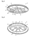
- the in the FIGS. 4 to 6 illustrated sealing body 10 of the sealing plug 8 includes a first sealing ring 12 having a sealing lip 14 and a second sealing ring 16 with a sealing lip 18.
- the sealing lips 14, 18 extend substantially on parallel planes and face each other, so that these during assembly of the sealing body 10th in the opening of a body part can rest on both sides of the opening sealingly on the bodywork component.
- the body part is in FIG. 10 indicated schematically (reference 5).
- the sealing body 10 has a plurality of connecting regions 20, which connect the two sealing rings 12, 16 with each other and which are arranged here in the radial direction on the inside of the sealing rings.
- the sealing body 10 has in its center on a sprue area 24 which is connected via a plurality of, here star-shaped to the second sealing ring 16 extending connecting webs 22 with the second sealing ring 16.
- the sprue area 24 has a central opening 26.
- the connecting webs 22 are provided with spring portions 28 which extend in extension of the connecting webs 22.
- the spring portions 28 are provided here on the "back" of the second, smaller sealing ring 16, ie on the side facing away from the larger sealing ring 12 and comes in contact with the edge of the body part upon insertion of the sealing plug into the opening of the body.
- the sealing body 12 is injection molded in one piece from a relatively soft plastic, which can melt under heat. Alternatively, it is possible to make it from another suitable, flexible material.
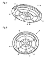
- base body 30 has at its radial edge two opposite, frustoconical support surfaces 32 and 34 which receive the sealing rings 12, 16 and this support.
- the lower support surface 34 has a plurality of recesses 36, 38 which receive the connecting webs 22 and the sprue area 24 of the sealing body 10.
- the arranged in the center of the sealing body 10 recess 38 is provided with a pin 40.
- the sealing body 10 is produced from a relatively soft plastic material by injection molding in a first method step.
- the main body 30 is made of a more stable plastic and connected to the sealing body.
- the base body 30 is injected directly into the sealing body 10 in a second injection process, so that the material of the sealing body, due to its lower melting point, slightly softened and glued the hard component of the body with the soft component of the sealing body.
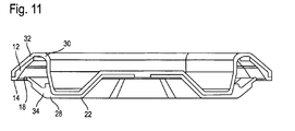
- sealing rings 12, 16 of the sealing body 10 on the inside of the support surfaces 32, 34 to this and are supported by the support surfaces 32, 34.
- the connecting webs 22 rest in the recesses 36 and thus form a stable connection between the base body 30 and the sealing body 10.
- the sprue area 24 lies in the central recess 38, so that the pin 40 of the main body 30 engages in the opening 26 of the sprue area 24 and additionally a positive connection between sealing body 10 and body 30 produces.
- the support surfaces 32, 34 support the sealing rings 12, 16 and keep them pressed against the surfaces of the body component, so that a reliable hold of the sealing plug 8 is ensured in the opening, but these have no contact with a vehicle component. A noise, for example due to vibrations, is so safely excluded.
- the sealing body 10 may for example be made at least partially of a heat-melting plastic, so that when a heating of the sealing plug for a cohesive connection between the body component and sealing plug 8 is made. On the other hand, a compensation of bumps is possible.
- the main body 30 is made of a plastic material which retains its strength at the melting temperature of the sealing plug 8, so that a secure hold of the sealing plug 8 is ensured on the body component during the melting process.
Landscapes
- Engineering & Computer Science (AREA)
- Mechanical Engineering (AREA)
- Chemical & Material Sciences (AREA)
- Combustion & Propulsion (AREA)
- Transportation (AREA)
- Injection Moulding Of Plastics Or The Like (AREA)
- Body Structure For Vehicles (AREA)
- Manufacturing & Machinery (AREA)
- Moulds For Moulding Plastics Or The Like (AREA)
- Closures For Containers (AREA)
Abstract
Description
- Die Erfindung betrifft einen Dichtstopfen zum Verschließen von Löchern, insbesondere in Fahrzeugkarosserien, mit einem Grundkörper, der aus einem ersten Kunststoffmaterial besteht, und einem Dichtkörper, der an dem Grundkörper angebracht ist, wobei der Dichtkörper zwei Dichtringe aufweist, die einander gegenüberliegend angeordnet sind, sodass diese auf der einen und der anderen Seite eines Karosserieteils anliegen können.
- Dichtstopfen werden in verschiedenen Ausführungsformen im Automobilbereich eingesetzt und dienen dazu, Öffnungen in Fahrzeugbauteilen dichtend zu verschließen. Die Dichtkörper haben beispielsweise einen Grundkörper aus einem relativ harten Kunststoff, der einen Stützkörper bildet bzw. dem Dichtstopfen Stabilität verleiht, sowie einen Dichtkörper aus einem relativ weichen Kunststoff, der am Bauteil anliegt und die Öffnung verschließt. Um die Öffnung besonders dicht zu verschließen, sind aus dem Stand der Technik Dichtstopfen bekannt, die an beiden Seiten der Öffnung einen Dichtring aufweisen, der jeweils am Bauteil anliegt, so dass die Öffnung beidseitig abgedichtet ist. Diese Dichtkörper sind allerdings sehr aufwendig in der Herstellung, da auf beiden Seiten der Öffnung Dichtbereiche am Dichtstopfen angebracht werden müssen.
- Aufgabe der Erfindung ist es, einen Dichtstopfen bereitzustellen, der eine Öffnung beidseitig abdichten kann und bei einfacher Herstellung eine größere Stabilität bietet.
- Zur Lösung der Aufgabe ist ein Dichtstopfen zum Verschließen von Löchern, insbesondere in Fahrzeugkarosserien, vorgesehen, mit einem Grundkörper, der aus einem ersten Kunststoffmaterial besteht, und einem Dichtkörper, der an dem Grundkörper angebracht ist, wobei der Dichtkörper zwei Dichtringe aufweist, die einander gegenüberliegend angeordnet sind, sodass diese auf der einen und der anderen Seite eines Karosserieteils anliegen können. Der Dichtkörper weist einen Angussbereich und mehrere Verbindungsbereiche auf, mittels denen die beiden Dichtringe miteinander verbunden sind. Die Position der Dichtringe zueinander ist durch die Verbindungsbereiche fixiert, wodurch diese in montiertem Zustand an einem Karosserieteil nicht auseinandergedrückt werden können. Dadurch ist sichergestellt, dass beide Dichtringe am Karosserieteil anliegen und die Öffnung im Karosserieteil zuverlässig abdichten können. Durch die Verbindungsbereiche sind die beiden Dichtringe so miteinander verbunden, dass diese in einem Arbeitsgang gleichzeitig über den gemeinsamen Angussbereich gespritzt werden können, wodurch die Herstellungskosten reduziert werden können
- Vorzugsweise erstrecken sich zwischen dem Angussbereich und einem der beiden Dichtringe mehrere Verbindungsstege. Der Angussbereich ist also von den Dichtringen getrennt, so dass an diesen keine durch den Angussbereich verursachten Unebenheiten entstehen können. Zudem dienen die Verbindungsstege der Stabilisierung des Dichtkörpers und ermöglichen eine bessere Verbindung zwischen Grundkörper und Dichtkörper.
- Die Verbindungsstege erstrecken sich beispielsweise radial ausgehend von einem Zentrum, in dem der Angussbereich angeordnet sein kann, so dass ein gleichmäßiges Füllen einer Spritzgussform möglich ist.
- Vorzugsweise ist vorgesehen, dass auf der Rückseite eines der Dichtringe mehrere Federabschnitte ausgebildet sind, die über die benachbarten Flächen des Grundkörpers hervorstehen. Dies gewährleistet, dass bei der Montage des Dichtstopfens am Karosserieteil zuerst der Dichtkörper mit dem Karosserieteil in Kontakt kommt, was die Montage erleichtert und das Risiko einer Beschädigung des entsprechenden Dichtrings beim Einschnappen in die Öffnung verringert.
- Vorzugsweise erstrecken sich die Federabschnitte in Verlängerung der Verbindungsstege. Die Federabschnitte können also einteilig mit den Verbindungsstegen ausgeführt werden, so dass sich kein zusätzlicher Aufwand bei der Herstellung ergibt.
- Um die Verbindung zwischen Grundkörper und Dichtkörper zu verbessern, weist der Angussbereich beispielsweise eine mittige Öffnung auf, in die ein Zapfen des Grundkörpers eingreift. Neben der stoffschlüssigen Verbindung zwischen Grundkörper und Dichtkörper ist dadurch auch eine formschlüssige Verbindung zwischen den Bauteilen geschaffen, die eine besonders sichere Verbindung der Bauteile ermöglicht.
- Der Dichtkörper kann beispielsweise aus einem wärmeschmelzenden Kunststoff bestehen, sodass durch ein Erhitzen des Fahrzeugbauteils eine stoffschlüssige Verbindung zwischen Dichtstopfen und Fahrzeugbauteil hergestellt werden kann, wodurch die Öffnung im Fahrzeugbauteil zuverlässig abgedichtet ist. Zudem können durch den schmelzenden Dichtkörper Unebenheiten des Fahrzeugbauteils ausgeglichen werden.
- Vorzugsweise besteht der Grundkörper aus einem Kunststoffmaterial, das bei der Schmelztemperatur des Dichtkörpers seine Festigkeit behält, sodass der Dichtstopfen durch den Grundkörper auch während des Schmelzvorgangs sicher in der Öffnung gehalten ist.
- Weitere Vorteile und Merkmale ergeben sich aus der nachfolgenden Beschreibung in Verbindung mit den beigefügten Zeichnungen. In diesen zeigen:
-
Figur 1 eine perspektivische Ansicht eines erfindungsgemäßen Dichtstopfens, -
Figur 2 eine zweite perspektivische Ansicht des Dichtstopfens ausFigur 1 , -
Figur 3 eine dritte perspektivische Ansicht des Dichtstopfens ausFigur 1 -
Figur 4 eine perspektivische Ansicht des Dichtkörpers eines erfindungsgemäßen Dichtstopfens, -
Figur 5 eine zweite perspektivische Ansicht des Dichtkörpers ausFigur 4 , -
Figur 6 eine dritte perspektivische Ansicht des Dichtkörpers ausFigur 4 , -
Figur 7 eine perspektivische Ansicht des Grundkörpers eines erfindungsgemäßen Dichtstopfens, -
Figur 8 eine zweite perspektivische Ansicht des Grundkörpers ausFigur 7 , -
Figur 9 eine dritte perspektivische Ansicht des Grundkörpers ausFigur 7 , -
Figur 10 eine erste Schnittansicht durch den Dichtstopfen ausFigur 1 , und -
Figur 11 eine zweite Schnittansicht durch den Dichtstopfen ausFigur 1 . - Der in den
Figuren 1 bis 3 dargestellte Dichtstopfen 8 dient zum Abdichten von Öffnungen, beispielsweise in Fahrzeugkarosserien. Der Dichtstopfen 8 hat einen Dichtkörper 10 aus einem relativ flexiblen Kunststoffmaterial sowie einen Grundkörper 30 aus einem Kunststoffmaterial, das eine größere Härte aufweist als das Material des Dichtkörpers 10. Der Grundkörper 30 hat hier eine im Wesentlichen schüsselartige Bauform, so dass dieser die Öffnung im Karosseriebauteil abdecken und den Dichtkörper 10 stützen kann. Der Dichtkörper 10 weist eine im Wesentlichen ringförmige Struktur auf und ist mit dem Grundkörper 30 stoffschlüssig verbunden. - Der in den
Figuren 4 bis 6 dargestellte Dichtkörper 10 des Dichtstopfens 8 enthält einen ersten Dichtring 12 mit einer Dichtlippe 14 und einen zweiten Dichtring 16 mit einer Dichtlippe 18. Die Dichtlippen 14, 18 verlaufen im Wesentlichen auf parallelen Ebenen und sind einander zugewandt, so dass diese bei einer Montage des Dichtkörpers 10 in der Öffnung eines Karosserieteils auf beiden Seiten der Öffnung dichtend am Karosseriebauteil anliegen können. Das Karosserieteil ist inFigur 10 schematisch angedeutet (Bezugszeichen 5). Der Dichtkörper 10 weist mehrere Verbindungsbereiche 20 auf, die die beiden Dichtringe 12, 16 miteinander verbinden und die hier in radialer Richtung auf der Innenseite der Dichtringe angeordnet sind. - Der Dichtkörper 10 weist in seinem Zentrum einen Angussbereich 24 auf, der über mehrere, hier sternförmig zum zweiten Dichtring 16 verlaufende Verbindungsstege 22 mit dem zweiten Dichtring 16 verbunden ist. Der Angussbereich 24 weist eine mittige Öffnung 26 auf. Wie insbesondere in
Figur 5 zu sehen ist, sind die Verbindungsstege 22 mit Federabschnitten 28 versehen, die sich in Verlängerung der Verbindungsstege 22 erstrecken. Die Federabschnitte 28 sind hier auf der "Rückseite" des zweiten, kleineren Dichtrings 16 vorgesehen, also auf der Seite, die vom größeren Dichtring 12 abgewandt ist und beim Einsetzen des Dichtstopfens in die Öffnung der Karosserie mit dem Rand des Karosserieteils in Kontakt kommt. Der Dichtkörper 12 ist einstückig aus einem relativ weichen Kunststoff spritzgegossen, der unter Wärmeeinwirkung schmelzen kann. Alternativ ist möglich, ihn aus einem anderen geeigneten, flexiblen Material herzustellen. - Der in den
Figuren 7 bis 9 dargestellte Grundkörper 30 weist an seinem radialen Rand zwei gegenüberliegende, kegelstumpfartig ausgebildete Stützflächen 32 und 34 auf, die die Dichtringe 12, 16 aufnehmen und diese stützen. Die untere Stützfläche 34 weist mehrere Aussparungen 36, 38 auf, die die Verbindungsstege 22 sowie den Angussbereich 24 des Dichtkörpers 10 aufnehmen. Die im Zentrum des Dichtkörpers 10 angeordneten Aussparung 38 ist mit einem Zapfen 40 versehen. - Zur Herstellung des Dichtstopfens 8 wird in einem ersten Verfahrensschritt der Dichtkörper 10 aus einem relativ weichen Kunststoff durch Spritzgiessen hergestellt. In einem zweiten Verfahrensschritt wird der Grundkörper 30 aus einem stabileren Kunststoff hergestellt und mit dem Dichtkörper verbunden. Vorzugsweise wird der Grundkörper 30 in einem zweiten Spritzvorgang direkt an den Dichtkörper 10 angespritzt, so dass das Material des Dichtkörpers, aufgrund seines niedrigeren Schmelzpunktes, leicht erweicht und die harte Komponente des Grundkörpers mit der weichen Komponente des Dichtkörpers verklebt.
- Wie in den
Figuren 10 und11 zu sehen ist, liegen die Dichtringe 12, 16 des Dichtkörpers 10 auf der Innenseite der Stützflächen 32, 34 an diesen an und werden so von den Stützflächen 32, 34 gestützt. Die Verbindungsstege 22 liegen in den Aussparungen 36 an und bilden so eine stabile Verbindung zwischen Grundkörper 30 und Dichtkörper 10. Der Angussbereich 24 liegt in der mittigen Aussparung 38, sodass der Zapfen 40 des Grundkörpers 30 in die Öffnung 26 des Angussbereichs 24 eingreift und zusätzlich eine formschlüssige Verbindung zwischen Dichtkörper 10 und Grundkörper 30 herstellt. - Wie auch insbesondere in
Figur 2 zu sehen ist, stehen die am zweiten Dichtring 16 vorgesehenen Federelemente 28 des Dichtkörpers 10 in radialer Richtung über die jeweils benachbarten Bereiche des Grundkörpers 30 vor. Bei der Montage des Dichtstopfens 8 kann so der Dichtring 12 flexibel nachgeben, so dass die Montage des Dichtstopfens erleichtert wird. - Wie in den
Figuren 10 und11 zu sehen ist, stehen die Dichtlippen 14, 18 der Dichtringe 12, 16 jeweils in Richtung zur andere Dichtlippe 14, 18 über den Grundkörper 30 vor, so dass der Dichtstopfen 8 in eingebautem Zustand nur mit dem Dichtkörper 10 mit dem Karosseriebauteil in Anlage gelangt. Die Stützflächen 32, 34 unterstützen zwar die Dichtringe 12, 16 und halten diese an die Flächen des Karosseriebauteils gedrückt, so dass ein zuverlässiger Halt des Dichtstopfens 8 in der Öffnung gewährleistet ist, diese haben aber keinen Kontakt zu einem Fahrzeugbauteil an. Eine Geräuschbildung, beispielsweise durch Vibrationen, ist so sicher ausgeschlossen. - Der Dichtkörper 10 kann beispielsweise zumindest teilweise aus einem wärmeschmelzenden Kunststoff hergestellt sein, so dass bei einer Erwärmung des Dichtstopfens zum einen eine stoffschlüssige Verbindung zwischen Karosseriebauteil und Dichtstopfen 8 hergestellt ist. Zum anderen ist dadurch ein Ausgleich von Unebenheiten möglich. Der Grundkörper 30 ist aus einem Kunststoffmaterial hergestellt, das bei der Schmelztemperatur des Dichtstopfens 8 seine Festigkeit behält, so dass auch während des Schmelzvorganges ein sicherer Halt des Dichtstopfens 8 am Karosseriebauteil gewährleistet ist.
Claims (8)
- Dichtstopfen (8) zum Verschließen von Löchern, insbesondere in Fahrzeugkarosserien, mit einem Grundkörper (30), der aus einem ersten Kunststoffmaterial besteht, und einem Dichtkörper (10), der an dem Grundkörper (30) angebracht ist, wobei der Dichtkörper (10) zwei Dichtringe (12, 16) aufweist, die einander gegenüberliegend angeordnet sind, sodass diese auf der einen und der anderen Seite eines Karosserieteils anliegen können, dadurch gekennzeichnet, dass der Dichtkörper (10) einen Angussbereich (24) und mehrere Verbindungsbereiche (20) aufweist, mittels denen die beiden Dichtringe (12, 16) miteinander verbunden sind.
- Dichtstopfen nach Anspruch 1, dadurch gekennzeichnet, dass sich zwischen dem Angussbereich (24) und einem der beiden Dichtringe (12, 16) mehrere Verbindungsstege (22) erstrecken.
- Dichtstopfen nach Anspruch 2, dadurch gekennzeichnet, dass die Verbindungsstege (22) sich radial ausgehend von einem Zentrum erstrecken.
- Dichtstopfen nach einem der vorhergehenden Ansprüche, dadurch gekennzeichnet, dass auf der Rückseite eines der Dichtringe (12, 16) mehrere Federabschnitte (28) ausgebildet sind, die über die benachbarten Flächen des Grundkörpers (30) hervorstehen.
- Dichtstopfen nach Anspruch 4 in Verbindung mit Anspruch 2, dadurch gekennzeichnet, dass die Federabschnitte (28) sich in Verlängerung der Verbindungsstege (22) erstrecken.
- Dichtstopfen nach einem der vorhergehenden Ansprüche, dadurch gekennzeichnet, dass der Angussbereich (24) des Dichtkörpers (10) mit einer mittigen Öffnung (26) versehen ist, in der ein Zapfen (40) des Grundkörpers (30) eingreift.
- Dichtstopfen nach einem der vorhergehenden Ansprüche, dadurch gekennzeichnet, dass der Dichtkörper (10) aus einem wärmeschmelzenden Klebstoff besteht.
- Dichtstopfen nach einem der vorhergehenden Ansprüche, dadurch gekennzeichnet, dass der Grundkörper (30) aus einem Kunststoffmaterial besteht, das bei der Schmelztemperatur des Dichtkörpers (10) seine Festigkeit behält.
Applications Claiming Priority (1)
| Application Number | Priority Date | Filing Date | Title |
|---|---|---|---|
| DE201020005749 DE202010005749U1 (de) | 2010-04-19 | 2010-04-19 | Dichtstopfen |
Publications (2)
| Publication Number | Publication Date |
|---|---|
| EP2377748A1 true EP2377748A1 (de) | 2011-10-19 |
| EP2377748B1 EP2377748B1 (de) | 2017-03-15 |
Family
ID=44070076
Family Applications (1)
| Application Number | Title | Priority Date | Filing Date |
|---|---|---|---|
| EP11003119.2A Active EP2377748B1 (de) | 2010-04-19 | 2011-04-13 | Dichtstopfen |
Country Status (5)
| Country | Link |
|---|---|
| EP (1) | EP2377748B1 (de) |
| KR (1) | KR101800828B1 (de) |
| CN (1) | CN102219031B (de) |
| DE (1) | DE202010005749U1 (de) |
| ES (1) | ES2626917T3 (de) |
Cited By (3)
| Publication number | Priority date | Publication date | Assignee | Title |
|---|---|---|---|---|
| EP2810855A1 (de) * | 2013-06-07 | 2014-12-10 | TRW Automotive Electronics & Components GmbH | Dichtstopfen |
| DE102015102169A1 (de) * | 2015-02-16 | 2016-08-18 | Trw Automotive Electronics & Components Gmbh | Verschlussstopfen |
| WO2018102060A1 (en) * | 2016-12-01 | 2018-06-07 | Illinois Tool Works Inc. | Adaptable sealing hole plug |
Families Citing this family (5)
| Publication number | Priority date | Publication date | Assignee | Title |
|---|---|---|---|---|
| ES2415758B1 (es) * | 2011-06-20 | 2014-09-09 | Illinois Tool Works, Inc. | Tapón obturador de orificios |
| JP6214335B2 (ja) * | 2013-10-24 | 2017-10-18 | 株式会社ニフコ | ホールプラグ |
| DE102013112629A1 (de) * | 2013-11-15 | 2015-05-21 | Trw Automotive Electronics & Components Gmbh | Verschlussstopfen |
| DE102017201298B4 (de) | 2017-01-27 | 2025-05-08 | Bayerische Motoren Werke Aktiengesellschaft | Stopfen für ein Bauteil, insbesondere eines Fahrzeugs, sowie Halteanordnung eines solchen Stopfens an einem Bauteil |
| US20250074661A1 (en) * | 2023-09-05 | 2025-03-06 | Illinois Tool Works Inc. | Sealing Plug |
Citations (2)
| Publication number | Priority date | Publication date | Assignee | Title |
|---|---|---|---|---|
| EP1375308A1 (de) * | 2002-06-19 | 2004-01-02 | I.T.W. Espana, S.A. | Verschlussdeckel zum Verschliessen von Öffnungen |
| WO2007093862A1 (en) * | 2006-02-16 | 2007-08-23 | Itw Automotive Products Gmbh & Co. Kg | A sealing plug with a pressure-compensating chamber |
Family Cites Families (9)
| Publication number | Priority date | Publication date | Assignee | Title |
|---|---|---|---|---|
| DE9320338U1 (de) * | 1993-06-30 | 1994-05-05 | Trw United-Carr Gmbh & Co Kg, 67677 Enkenbach-Alsenborn | Verschlußdeckel |
| FR2731984B1 (fr) * | 1995-03-21 | 1997-04-30 | Rapid Sa | Bouchon d'obturation d'une ouverture quelconque et procede de fabrication de ce bouchon |
| DE19546160A1 (de) * | 1995-12-11 | 1997-06-12 | United Carr Gmbh Trw | Auf zwei Kunststoffkomponenten bestehender Verschlußdeckel |
| DE29915819U1 (de) * | 1999-09-08 | 2000-01-13 | TRW Automotive Electronics & Components GmbH & Co.KG, 67677 Enkenbach-Alsenborn | Verschlußelement |
| DE20107612U1 (de) * | 2001-05-04 | 2001-10-18 | TRW Automotive Electronics & Components GmbH & Co. KG, 78315 Radolfzell | Verschlussdeckel |
| DE20304994U1 (de) * | 2003-03-27 | 2003-07-31 | TRW Automotive Electronics & Components GmbH & Co.KG, 67677 Enkenbach-Alsenborn | Karosseriestopfen |
| DE102006049609A1 (de) * | 2006-10-20 | 2008-04-30 | Trw Automotive Electronics & Components Gmbh & Co. Kg | Verfahren zum Abdichten einer Öffnung in einem Bauteil |
| JP4896679B2 (ja) * | 2006-11-24 | 2012-03-14 | 株式会社パイオラックス | ホールプラグ |
| DE102007026543B4 (de) * | 2007-06-08 | 2017-02-09 | Itw Fastener Products Gmbh | Entwässerungsstopfen |
-
2010
- 2010-04-19 DE DE201020005749 patent/DE202010005749U1/de not_active Expired - Lifetime
-
2011
- 2011-04-13 ES ES11003119.2T patent/ES2626917T3/es active Active
- 2011-04-13 EP EP11003119.2A patent/EP2377748B1/de active Active
- 2011-04-18 KR KR1020110035851A patent/KR101800828B1/ko not_active Expired - Fee Related
- 2011-04-19 CN CN201110097226.4A patent/CN102219031B/zh active Active
Patent Citations (2)
| Publication number | Priority date | Publication date | Assignee | Title |
|---|---|---|---|---|
| EP1375308A1 (de) * | 2002-06-19 | 2004-01-02 | I.T.W. Espana, S.A. | Verschlussdeckel zum Verschliessen von Öffnungen |
| WO2007093862A1 (en) * | 2006-02-16 | 2007-08-23 | Itw Automotive Products Gmbh & Co. Kg | A sealing plug with a pressure-compensating chamber |
Cited By (6)
| Publication number | Priority date | Publication date | Assignee | Title |
|---|---|---|---|---|
| EP2810855A1 (de) * | 2013-06-07 | 2014-12-10 | TRW Automotive Electronics & Components GmbH | Dichtstopfen |
| DE102015102169A1 (de) * | 2015-02-16 | 2016-08-18 | Trw Automotive Electronics & Components Gmbh | Verschlussstopfen |
| WO2016131573A1 (de) * | 2015-02-16 | 2016-08-25 | Trw Automotive Electronics & Components Gmbh | Verschlussstopfen |
| DE102015102169B4 (de) * | 2015-02-16 | 2016-08-25 | Trw Automotive Electronics & Components Gmbh | Verschlussstopfen |
| WO2018102060A1 (en) * | 2016-12-01 | 2018-06-07 | Illinois Tool Works Inc. | Adaptable sealing hole plug |
| US11001312B2 (en) | 2016-12-01 | 2021-05-11 | Illinois Tool Works Inc. | Adaptable sealing hole plug |
Also Published As
| Publication number | Publication date |
|---|---|
| ES2626917T3 (es) | 2017-07-26 |
| EP2377748B1 (de) | 2017-03-15 |
| KR20110117001A (ko) | 2011-10-26 |
| DE202010005749U1 (de) | 2011-09-02 |
| CN102219031B (zh) | 2015-09-02 |
| CN102219031A (zh) | 2011-10-19 |
| KR101800828B1 (ko) | 2017-11-23 |
Similar Documents
| Publication | Publication Date | Title |
|---|---|---|
| EP2377748B1 (de) | Dichtstopfen | |
| DE102009018395B4 (de) | Dichtstopfen | |
| DE102010024870A1 (de) | Vorrichtung zum Befestigen eines Bauteils an einem Befestigungsbolzen | |
| WO2016131573A1 (de) | Verschlussstopfen | |
| DE602005002868T2 (de) | Kraftfahrzeugrahmenanordnung | |
| DE202011103327U1 (de) | Baugruppe mit mindestens zwei aneinander fixierten Bauteilen | |
| DE102015001331A1 (de) | Feststehende Aufspannplatte einer Spritzgießmaschine | |
| DE102017105616A1 (de) | Tankmuldenanordnung | |
| EP3919354B1 (de) | Verschlussstopfen | |
| DE102011056968A1 (de) | Clip | |
| DE102014103576B4 (de) | Gehäuse für lenkgetriebe | |
| EP1854681A2 (de) | Luftkanal für ein Kraftfahrzeug | |
| DE102007026544A1 (de) | Verschlussstopfen | |
| WO2008086841A1 (de) | Dichtungsanordnung für ein plattenelement einer brennstoffzelle | |
| DE102012101396B3 (de) | Elastische Ankopplung einer einen Flansch aufweisenden Baueinheit, um einen passiven Schwingungstilger auszubilden | |
| DE102015114238A1 (de) | Anbindungssystem und Verfahren zur Befestigung eines Bauteils an einer Fahrzeugkarosserie | |
| DE102014112889A1 (de) | Dichtstopfen | |
| DE2718228C2 (de) | Kondensatorabdeckscheibe | |
| DE102005022937B4 (de) | Verfahren zur Herstellung einer längswasserdichten Anordnung eines Leitungsstranges in einer elastischen Tülle | |
| DE10231274A1 (de) | Einsatzteil für eine Wandöffnung, insbesondere an einer Fahrzeugkarosserie | |
| WO2013060397A1 (de) | Entkopplungselement und anordnung zur schwingungsentkoppelnden befestigung eines funktionsmoduls an einem fahrzeugteil sowie verfahren zum herstellen eines solchen | |
| DE102008006461A1 (de) | Verfahren zur Verbindung wenigstens eines ersten Kunststoff-Elements mit wenigstens einem zweiten Kunststoff-Element | |
| DE102010048690A1 (de) | Zierleistenanordnung für ein Fahrzeug | |
| WO2010051901A2 (de) | Dichtstopfen | |
| WO2022017978A1 (de) | Befestigungsanordnung, kraftfahrzeug |
Legal Events
| Date | Code | Title | Description |
|---|---|---|---|
| AK | Designated contracting states |
Kind code of ref document: A1 Designated state(s): AL AT BE BG CH CY CZ DE DK EE ES FI FR GB GR HR HU IE IS IT LI LT LU LV MC MK MT NL NO PL PT RO RS SE SI SK SM TR |
|
| AX | Request for extension of the european patent |
Extension state: BA ME |
|
| PUAI | Public reference made under article 153(3) epc to a published international application that has entered the european phase |
Free format text: ORIGINAL CODE: 0009012 |
|
| 17P | Request for examination filed |
Effective date: 20120301 |
|
| 17Q | First examination report despatched |
Effective date: 20140821 |
|
| GRAP | Despatch of communication of intention to grant a patent |
Free format text: ORIGINAL CODE: EPIDOSNIGR1 |
|
| INTG | Intention to grant announced |
Effective date: 20160407 |
|
| INTC | Intention to grant announced (deleted) | ||
| GRAP | Despatch of communication of intention to grant a patent |
Free format text: ORIGINAL CODE: EPIDOSNIGR1 |
|
| INTG | Intention to grant announced |
Effective date: 20160902 |
|
| GRAJ | Information related to disapproval of communication of intention to grant by the applicant or resumption of examination proceedings by the epo deleted |
Free format text: ORIGINAL CODE: EPIDOSDIGR1 |
|
| GRAP | Despatch of communication of intention to grant a patent |
Free format text: ORIGINAL CODE: EPIDOSNIGR1 |
|
| STAA | Information on the status of an ep patent application or granted ep patent |
Free format text: STATUS: GRANT OF PATENT IS INTENDED |
|
| INTC | Intention to grant announced (deleted) | ||
| INTG | Intention to grant announced |
Effective date: 20161109 |
|
| GRAS | Grant fee paid |
Free format text: ORIGINAL CODE: EPIDOSNIGR3 |
|
| GRAA | (expected) grant |
Free format text: ORIGINAL CODE: 0009210 |
|
| STAA | Information on the status of an ep patent application or granted ep patent |
Free format text: STATUS: THE PATENT HAS BEEN GRANTED |
|
| RAP1 | Party data changed (applicant data changed or rights of an application transferred) |
Owner name: ITW FASTENER PRODUCTS GMBH |
|
| AK | Designated contracting states |
Kind code of ref document: B1 Designated state(s): AL AT BE BG CH CY CZ DE DK EE ES FI FR GB GR HR HU IE IS IT LI LT LU LV MC MK MT NL NO PL PT RO RS SE SI SK SM TR |
|
| REG | Reference to a national code |
Ref country code: CH Ref legal event code: EP Ref country code: GB Ref legal event code: FG4D Free format text: NOT ENGLISH |
|
| REG | Reference to a national code |
Ref country code: IE Ref legal event code: FG4D Free format text: LANGUAGE OF EP DOCUMENT: GERMAN |
|
| REG | Reference to a national code |
Ref country code: AT Ref legal event code: REF Ref document number: 875220 Country of ref document: AT Kind code of ref document: T Effective date: 20170415 |
|
| REG | Reference to a national code |
Ref country code: DE Ref legal event code: R096 Ref document number: 502011011817 Country of ref document: DE |
|
| REG | Reference to a national code |
Ref country code: FR Ref legal event code: PLFP Year of fee payment: 7 |
|
| RAP2 | Party data changed (patent owner data changed or rights of a patent transferred) |
Owner name: ILLINOIS TOOL WORKS INC. |
|
| REG | Reference to a national code |
Ref country code: NL Ref legal event code: MP Effective date: 20170315 |
|
| REG | Reference to a national code |
Ref country code: LT Ref legal event code: MG4D |
|
| REG | Reference to a national code |
Ref country code: ES Ref legal event code: FG2A Ref document number: 2626917 Country of ref document: ES Kind code of ref document: T3 Effective date: 20170726 |
|
| PG25 | Lapsed in a contracting state [announced via postgrant information from national office to epo] |
Ref country code: HR Free format text: LAPSE BECAUSE OF FAILURE TO SUBMIT A TRANSLATION OF THE DESCRIPTION OR TO PAY THE FEE WITHIN THE PRESCRIBED TIME-LIMIT Effective date: 20170315 Ref country code: NO Free format text: LAPSE BECAUSE OF FAILURE TO SUBMIT A TRANSLATION OF THE DESCRIPTION OR TO PAY THE FEE WITHIN THE PRESCRIBED TIME-LIMIT Effective date: 20170615 Ref country code: GR Free format text: LAPSE BECAUSE OF FAILURE TO SUBMIT A TRANSLATION OF THE DESCRIPTION OR TO PAY THE FEE WITHIN THE PRESCRIBED TIME-LIMIT Effective date: 20170616 Ref country code: FI Free format text: LAPSE BECAUSE OF FAILURE TO SUBMIT A TRANSLATION OF THE DESCRIPTION OR TO PAY THE FEE WITHIN THE PRESCRIBED TIME-LIMIT Effective date: 20170315 Ref country code: LT Free format text: LAPSE BECAUSE OF FAILURE TO SUBMIT A TRANSLATION OF THE DESCRIPTION OR TO PAY THE FEE WITHIN THE PRESCRIBED TIME-LIMIT Effective date: 20170315 |
|
| PG25 | Lapsed in a contracting state [announced via postgrant information from national office to epo] |
Ref country code: RS Free format text: LAPSE BECAUSE OF FAILURE TO SUBMIT A TRANSLATION OF THE DESCRIPTION OR TO PAY THE FEE WITHIN THE PRESCRIBED TIME-LIMIT Effective date: 20170315 Ref country code: SE Free format text: LAPSE BECAUSE OF FAILURE TO SUBMIT A TRANSLATION OF THE DESCRIPTION OR TO PAY THE FEE WITHIN THE PRESCRIBED TIME-LIMIT Effective date: 20170315 Ref country code: LV Free format text: LAPSE BECAUSE OF FAILURE TO SUBMIT A TRANSLATION OF THE DESCRIPTION OR TO PAY THE FEE WITHIN THE PRESCRIBED TIME-LIMIT Effective date: 20170315 Ref country code: BG Free format text: LAPSE BECAUSE OF FAILURE TO SUBMIT A TRANSLATION OF THE DESCRIPTION OR TO PAY THE FEE WITHIN THE PRESCRIBED TIME-LIMIT Effective date: 20170615 |
|
| PGFP | Annual fee paid to national office [announced via postgrant information from national office to epo] |
Ref country code: ES Payment date: 20170503 Year of fee payment: 7 |
|
| PG25 | Lapsed in a contracting state [announced via postgrant information from national office to epo] |
Ref country code: NL Free format text: LAPSE BECAUSE OF FAILURE TO SUBMIT A TRANSLATION OF THE DESCRIPTION OR TO PAY THE FEE WITHIN THE PRESCRIBED TIME-LIMIT Effective date: 20170315 |
|
| PG25 | Lapsed in a contracting state [announced via postgrant information from national office to epo] |
Ref country code: EE Free format text: LAPSE BECAUSE OF FAILURE TO SUBMIT A TRANSLATION OF THE DESCRIPTION OR TO PAY THE FEE WITHIN THE PRESCRIBED TIME-LIMIT Effective date: 20170315 Ref country code: CZ Free format text: LAPSE BECAUSE OF FAILURE TO SUBMIT A TRANSLATION OF THE DESCRIPTION OR TO PAY THE FEE WITHIN THE PRESCRIBED TIME-LIMIT Effective date: 20170315 Ref country code: SK Free format text: LAPSE BECAUSE OF FAILURE TO SUBMIT A TRANSLATION OF THE DESCRIPTION OR TO PAY THE FEE WITHIN THE PRESCRIBED TIME-LIMIT Effective date: 20170315 Ref country code: RO Free format text: LAPSE BECAUSE OF FAILURE TO SUBMIT A TRANSLATION OF THE DESCRIPTION OR TO PAY THE FEE WITHIN THE PRESCRIBED TIME-LIMIT Effective date: 20170315 |
|
| PG25 | Lapsed in a contracting state [announced via postgrant information from national office to epo] |
Ref country code: SM Free format text: LAPSE BECAUSE OF FAILURE TO SUBMIT A TRANSLATION OF THE DESCRIPTION OR TO PAY THE FEE WITHIN THE PRESCRIBED TIME-LIMIT Effective date: 20170315 Ref country code: IS Free format text: LAPSE BECAUSE OF FAILURE TO SUBMIT A TRANSLATION OF THE DESCRIPTION OR TO PAY THE FEE WITHIN THE PRESCRIBED TIME-LIMIT Effective date: 20170715 Ref country code: PT Free format text: LAPSE BECAUSE OF FAILURE TO SUBMIT A TRANSLATION OF THE DESCRIPTION OR TO PAY THE FEE WITHIN THE PRESCRIBED TIME-LIMIT Effective date: 20170717 Ref country code: PL Free format text: LAPSE BECAUSE OF FAILURE TO SUBMIT A TRANSLATION OF THE DESCRIPTION OR TO PAY THE FEE WITHIN THE PRESCRIBED TIME-LIMIT Effective date: 20170315 |
|
| REG | Reference to a national code |
Ref country code: CH Ref legal event code: PL |
|
| REG | Reference to a national code |
Ref country code: DE Ref legal event code: R097 Ref document number: 502011011817 Country of ref document: DE |
|
| PLBE | No opposition filed within time limit |
Free format text: ORIGINAL CODE: 0009261 |
|
| STAA | Information on the status of an ep patent application or granted ep patent |
Free format text: STATUS: NO OPPOSITION FILED WITHIN TIME LIMIT |
|
| REG | Reference to a national code |
Ref country code: IE Ref legal event code: MM4A |
|
| PG25 | Lapsed in a contracting state [announced via postgrant information from national office to epo] |
Ref country code: MC Free format text: LAPSE BECAUSE OF FAILURE TO SUBMIT A TRANSLATION OF THE DESCRIPTION OR TO PAY THE FEE WITHIN THE PRESCRIBED TIME-LIMIT Effective date: 20170315 Ref country code: DK Free format text: LAPSE BECAUSE OF FAILURE TO SUBMIT A TRANSLATION OF THE DESCRIPTION OR TO PAY THE FEE WITHIN THE PRESCRIBED TIME-LIMIT Effective date: 20170315 |
|
| 26N | No opposition filed |
Effective date: 20171218 |
|
| GBPC | Gb: european patent ceased through non-payment of renewal fee |
Effective date: 20170615 |
|
| PG25 | Lapsed in a contracting state [announced via postgrant information from national office to epo] |
Ref country code: CH Free format text: LAPSE BECAUSE OF NON-PAYMENT OF DUE FEES Effective date: 20170430 Ref country code: SI Free format text: LAPSE BECAUSE OF FAILURE TO SUBMIT A TRANSLATION OF THE DESCRIPTION OR TO PAY THE FEE WITHIN THE PRESCRIBED TIME-LIMIT Effective date: 20170315 Ref country code: LU Free format text: LAPSE BECAUSE OF NON-PAYMENT OF DUE FEES Effective date: 20170413 Ref country code: LI Free format text: LAPSE BECAUSE OF NON-PAYMENT OF DUE FEES Effective date: 20170430 |
|
| REG | Reference to a national code |
Ref country code: BE Ref legal event code: MM Effective date: 20170430 |
|
| REG | Reference to a national code |
Ref country code: FR Ref legal event code: PLFP Year of fee payment: 8 |
|
| PG25 | Lapsed in a contracting state [announced via postgrant information from national office to epo] |
Ref country code: GB Free format text: LAPSE BECAUSE OF NON-PAYMENT OF DUE FEES Effective date: 20170615 Ref country code: IE Free format text: LAPSE BECAUSE OF NON-PAYMENT OF DUE FEES Effective date: 20170413 |
|
| PG25 | Lapsed in a contracting state [announced via postgrant information from national office to epo] |
Ref country code: BE Free format text: LAPSE BECAUSE OF NON-PAYMENT OF DUE FEES Effective date: 20170430 |
|
| REG | Reference to a national code |
Ref country code: AT Ref legal event code: MM01 Ref document number: 875220 Country of ref document: AT Kind code of ref document: T Effective date: 20170413 |
|
| PG25 | Lapsed in a contracting state [announced via postgrant information from national office to epo] |
Ref country code: AT Free format text: LAPSE BECAUSE OF NON-PAYMENT OF DUE FEES Effective date: 20170413 |
|
| PGFP | Annual fee paid to national office [announced via postgrant information from national office to epo] |
Ref country code: IT Payment date: 20180423 Year of fee payment: 8 |
|
| PG25 | Lapsed in a contracting state [announced via postgrant information from national office to epo] |
Ref country code: MT Free format text: LAPSE BECAUSE OF FAILURE TO SUBMIT A TRANSLATION OF THE DESCRIPTION OR TO PAY THE FEE WITHIN THE PRESCRIBED TIME-LIMIT Effective date: 20170315 |
|
| PG25 | Lapsed in a contracting state [announced via postgrant information from national office to epo] |
Ref country code: HU Free format text: LAPSE BECAUSE OF FAILURE TO SUBMIT A TRANSLATION OF THE DESCRIPTION OR TO PAY THE FEE WITHIN THE PRESCRIBED TIME-LIMIT; INVALID AB INITIO Effective date: 20110413 |
|
| PGFP | Annual fee paid to national office [announced via postgrant information from national office to epo] |
Ref country code: FR Payment date: 20190425 Year of fee payment: 9 |
|
| REG | Reference to a national code |
Ref country code: ES Ref legal event code: FD2A Effective date: 20190911 |
|
| PG25 | Lapsed in a contracting state [announced via postgrant information from national office to epo] |
Ref country code: ES Free format text: LAPSE BECAUSE OF NON-PAYMENT OF DUE FEES Effective date: 20180414 Ref country code: CY Free format text: LAPSE BECAUSE OF NON-PAYMENT OF DUE FEES Effective date: 20170315 |
|
| PG25 | Lapsed in a contracting state [announced via postgrant information from national office to epo] |
Ref country code: MK Free format text: LAPSE BECAUSE OF FAILURE TO SUBMIT A TRANSLATION OF THE DESCRIPTION OR TO PAY THE FEE WITHIN THE PRESCRIBED TIME-LIMIT Effective date: 20170315 |
|
| PG25 | Lapsed in a contracting state [announced via postgrant information from national office to epo] |
Ref country code: TR Free format text: LAPSE BECAUSE OF FAILURE TO SUBMIT A TRANSLATION OF THE DESCRIPTION OR TO PAY THE FEE WITHIN THE PRESCRIBED TIME-LIMIT Effective date: 20170315 |
|
| PG25 | Lapsed in a contracting state [announced via postgrant information from national office to epo] |
Ref country code: IT Free format text: LAPSE BECAUSE OF NON-PAYMENT OF DUE FEES Effective date: 20190413 |
|
| PG25 | Lapsed in a contracting state [announced via postgrant information from national office to epo] |
Ref country code: AL Free format text: LAPSE BECAUSE OF FAILURE TO SUBMIT A TRANSLATION OF THE DESCRIPTION OR TO PAY THE FEE WITHIN THE PRESCRIBED TIME-LIMIT Effective date: 20170315 |
|
| PG25 | Lapsed in a contracting state [announced via postgrant information from national office to epo] |
Ref country code: FR Free format text: LAPSE BECAUSE OF NON-PAYMENT OF DUE FEES Effective date: 20200430 |
|
| P01 | Opt-out of the competence of the unified patent court (upc) registered |
Effective date: 20231101 |
|
| PGFP | Annual fee paid to national office [announced via postgrant information from national office to epo] |
Ref country code: DE Payment date: 20250429 Year of fee payment: 15 |