EP2377174B1 - High temperature, high efficiency thermoelectric module - Google Patents
High temperature, high efficiency thermoelectric module Download PDFInfo
- Publication number
- EP2377174B1 EP2377174B1 EP09833805.6A EP09833805A EP2377174B1 EP 2377174 B1 EP2377174 B1 EP 2377174B1 EP 09833805 A EP09833805 A EP 09833805A EP 2377174 B1 EP2377174 B1 EP 2377174B1
- Authority
- EP
- European Patent Office
- Prior art keywords
- legs
- thermoelectric
- temperature
- module
- thermoelectric module
- Prior art date
- Legal status (The legal status is an assumption and is not a legal conclusion. Google has not performed a legal analysis and makes no representation as to the accuracy of the status listed.)
- Not-in-force
Links
- OCGWQDWYSQAFTO-UHFFFAOYSA-N tellanylidenelead Chemical compound [Pb]=[Te] OCGWQDWYSQAFTO-UHFFFAOYSA-N 0.000 claims description 133
- 239000000463 material Substances 0.000 claims description 111
- XEEYBQQBJWHFJM-UHFFFAOYSA-N Iron Chemical compound [Fe] XEEYBQQBJWHFJM-UHFFFAOYSA-N 0.000 claims description 79
- 229910002665 PbTe Inorganic materials 0.000 claims description 78
- 229910052742 iron Inorganic materials 0.000 claims description 33
- XSOKHXFFCGXDJZ-UHFFFAOYSA-N telluride(2-) Chemical compound [Te-2] XSOKHXFFCGXDJZ-UHFFFAOYSA-N 0.000 claims description 26
- 229910052751 metal Inorganic materials 0.000 claims description 24
- 239000002184 metal Substances 0.000 claims description 24
- RVTZCBVAJQQJTK-UHFFFAOYSA-N oxygen(2-);zirconium(4+) Chemical compound [O-2].[O-2].[Zr+4] RVTZCBVAJQQJTK-UHFFFAOYSA-N 0.000 claims description 15
- 229910001928 zirconium oxide Inorganic materials 0.000 claims description 15
- 239000004020 conductor Substances 0.000 claims description 14
- 239000010445 mica Substances 0.000 claims description 10
- 229910052618 mica group Inorganic materials 0.000 claims description 10
- 229910052714 tellurium Inorganic materials 0.000 claims description 9
- 239000002105 nanoparticle Substances 0.000 claims description 8
- PORWMNRCUJJQNO-UHFFFAOYSA-N tellurium atom Chemical compound [Te] PORWMNRCUJJQNO-UHFFFAOYSA-N 0.000 claims description 8
- HCHKCACWOHOZIP-UHFFFAOYSA-N Zinc Chemical compound [Zn] HCHKCACWOHOZIP-UHFFFAOYSA-N 0.000 claims description 7
- 229910052725 zinc Inorganic materials 0.000 claims description 7
- 239000011701 zinc Substances 0.000 claims description 7
- 229910005642 SnTe Inorganic materials 0.000 claims description 5
- 229910052782 aluminium Inorganic materials 0.000 claims description 5
- XAGFODPZIPBFFR-UHFFFAOYSA-N aluminium Chemical compound [Al] XAGFODPZIPBFFR-UHFFFAOYSA-N 0.000 claims description 5
- 229920000106 Liquid crystal polymer Polymers 0.000 claims description 4
- 239000004977 Liquid-crystal polymers (LCPs) Substances 0.000 claims description 4
- 239000002775 capsule Substances 0.000 claims description 4
- 229910010293 ceramic material Inorganic materials 0.000 claims description 4
- 150000002739 metals Chemical class 0.000 claims description 4
- ZOKXTWBITQBERF-UHFFFAOYSA-N Molybdenum Chemical compound [Mo] ZOKXTWBITQBERF-UHFFFAOYSA-N 0.000 claims description 3
- 229920001971 elastomer Polymers 0.000 claims description 3
- 239000000806 elastomer Substances 0.000 claims description 3
- 238000009413 insulation Methods 0.000 claims description 3
- 229910052750 molybdenum Inorganic materials 0.000 claims description 3
- 239000011733 molybdenum Substances 0.000 claims description 3
- 229920002379 silicone rubber Polymers 0.000 claims description 3
- 239000004945 silicone rubber Substances 0.000 claims description 3
- 239000002918 waste heat Substances 0.000 claims description 3
- 229920005989 resin Polymers 0.000 claims description 2
- 239000011347 resin Substances 0.000 claims description 2
- 229910002899 Bi2Te3 Inorganic materials 0.000 description 60
- 229910045601 alloy Inorganic materials 0.000 description 53
- 239000000956 alloy Substances 0.000 description 53
- 238000000034 method Methods 0.000 description 45
- 229910052797 bismuth Inorganic materials 0.000 description 22
- JCXGWMGPZLAOME-UHFFFAOYSA-N bismuth atom Chemical compound [Bi] JCXGWMGPZLAOME-UHFFFAOYSA-N 0.000 description 22
- 229910052757 nitrogen Inorganic materials 0.000 description 18
- 229910052698 phosphorus Inorganic materials 0.000 description 18
- 125000006850 spacer group Chemical group 0.000 description 13
- 238000003825 pressing Methods 0.000 description 12
- 229920013651 Zenite Polymers 0.000 description 11
- 239000000843 powder Substances 0.000 description 11
- 230000008569 process Effects 0.000 description 11
- PGNWIWKMXVDXHP-UHFFFAOYSA-L zinc;1,3-benzothiazole-2-thiolate Chemical compound [Zn+2].C1=CC=C2SC([S-])=NC2=C1.C1=CC=C2SC([S-])=NC2=C1 PGNWIWKMXVDXHP-UHFFFAOYSA-L 0.000 description 11
- 238000013461 design Methods 0.000 description 9
- 238000007906 compression Methods 0.000 description 8
- 230000006835 compression Effects 0.000 description 8
- 238000004519 manufacturing process Methods 0.000 description 8
- 239000004964 aerogel Substances 0.000 description 7
- 238000003466 welding Methods 0.000 description 7
- 239000000835 fiber Substances 0.000 description 6
- 238000002347 injection Methods 0.000 description 6
- 239000007924 injection Substances 0.000 description 6
- 239000008188 pellet Substances 0.000 description 6
- 239000004065 semiconductor Substances 0.000 description 6
- 239000010949 copper Substances 0.000 description 5
- 238000005538 encapsulation Methods 0.000 description 5
- 238000005516 engineering process Methods 0.000 description 5
- 238000001704 evaporation Methods 0.000 description 5
- 230000008020 evaporation Effects 0.000 description 5
- 238000005245 sintering Methods 0.000 description 5
- 239000000758 substrate Substances 0.000 description 5
- 238000005382 thermal cycling Methods 0.000 description 5
- 229920001169 thermoplastic Polymers 0.000 description 5
- 239000004416 thermosoftening plastic Substances 0.000 description 5
- 229910052580 B4C Inorganic materials 0.000 description 4
- VYPSYNLAJGMNEJ-UHFFFAOYSA-N Silicium dioxide Chemical compound O=[Si]=O VYPSYNLAJGMNEJ-UHFFFAOYSA-N 0.000 description 4
- PNEYBMLMFCGWSK-UHFFFAOYSA-N aluminium oxide Inorganic materials [O-2].[O-2].[O-2].[Al+3].[Al+3] PNEYBMLMFCGWSK-UHFFFAOYSA-N 0.000 description 4
- 238000013459 approach Methods 0.000 description 4
- 239000011230 binding agent Substances 0.000 description 4
- 239000000919 ceramic Substances 0.000 description 4
- 239000010408 film Substances 0.000 description 4
- 238000009834 vaporization Methods 0.000 description 4
- 230000008016 vaporization Effects 0.000 description 4
- XLYOFNOQVPJJNP-UHFFFAOYSA-N water Substances O XLYOFNOQVPJJNP-UHFFFAOYSA-N 0.000 description 4
- RYGMFSIKBFXOCR-UHFFFAOYSA-N Copper Chemical compound [Cu] RYGMFSIKBFXOCR-UHFFFAOYSA-N 0.000 description 3
- 229910017629 Sb2Te3 Inorganic materials 0.000 description 3
- XUIMIQQOPSSXEZ-UHFFFAOYSA-N Silicon Chemical compound [Si] XUIMIQQOPSSXEZ-UHFFFAOYSA-N 0.000 description 3
- 229910000577 Silicon-germanium Inorganic materials 0.000 description 3
- 230000008901 benefit Effects 0.000 description 3
- 230000015556 catabolic process Effects 0.000 description 3
- 238000000576 coating method Methods 0.000 description 3
- 229910052802 copper Inorganic materials 0.000 description 3
- 238000006731 degradation reaction Methods 0.000 description 3
- 238000009792 diffusion process Methods 0.000 description 3
- 239000000428 dust Substances 0.000 description 3
- 239000010439 graphite Substances 0.000 description 3
- 229910002804 graphite Inorganic materials 0.000 description 3
- 230000006872 improvement Effects 0.000 description 3
- 229910052740 iodine Inorganic materials 0.000 description 3
- OKJPEAGHQZHRQV-UHFFFAOYSA-N iodoform Chemical compound IC(I)I OKJPEAGHQZHRQV-UHFFFAOYSA-N 0.000 description 3
- 239000000203 mixture Substances 0.000 description 3
- 238000000465 moulding Methods 0.000 description 3
- 238000012545 processing Methods 0.000 description 3
- 229910052710 silicon Inorganic materials 0.000 description 3
- 239000010703 silicon Substances 0.000 description 3
- HBMJWWWQQXIZIP-UHFFFAOYSA-N silicon carbide Chemical compound [Si+]#[C-] HBMJWWWQQXIZIP-UHFFFAOYSA-N 0.000 description 3
- 229910010271 silicon carbide Inorganic materials 0.000 description 3
- 239000011734 sodium Substances 0.000 description 3
- ZCYVEMRRCGMTRW-UHFFFAOYSA-N 7553-56-2 Chemical compound [I] ZCYVEMRRCGMTRW-UHFFFAOYSA-N 0.000 description 2
- XKRFYHLGVUSROY-UHFFFAOYSA-N Argon Chemical compound [Ar] XKRFYHLGVUSROY-UHFFFAOYSA-N 0.000 description 2
- OKTJSMMVPCPJKN-UHFFFAOYSA-N Carbon Chemical compound [C] OKTJSMMVPCPJKN-UHFFFAOYSA-N 0.000 description 2
- 229910017231 MnTe Inorganic materials 0.000 description 2
- 239000000654 additive Substances 0.000 description 2
- 238000005266 casting Methods 0.000 description 2
- 239000002131 composite material Substances 0.000 description 2
- 230000008602 contraction Effects 0.000 description 2
- 239000000498 cooling water Substances 0.000 description 2
- 230000000694 effects Effects 0.000 description 2
- 230000005611 electricity Effects 0.000 description 2
- 239000011888 foil Substances 0.000 description 2
- 238000009472 formulation Methods 0.000 description 2
- 239000007789 gas Substances 0.000 description 2
- 238000001746 injection moulding Methods 0.000 description 2
- 239000011630 iodine Substances 0.000 description 2
- 238000005304 joining Methods 0.000 description 2
- 238000002844 melting Methods 0.000 description 2
- 230000008018 melting Effects 0.000 description 2
- 239000002991 molded plastic Substances 0.000 description 2
- 229910001175 oxide dispersion-strengthened alloy Inorganic materials 0.000 description 2
- 239000000123 paper Substances 0.000 description 2
- 239000011148 porous material Substances 0.000 description 2
- 229910021426 porous silicon Inorganic materials 0.000 description 2
- 238000004663 powder metallurgy Methods 0.000 description 2
- 238000010248 power generation Methods 0.000 description 2
- 230000005855 radiation Effects 0.000 description 2
- 238000011160 research Methods 0.000 description 2
- 230000000717 retained effect Effects 0.000 description 2
- 229910052708 sodium Inorganic materials 0.000 description 2
- 239000007787 solid Substances 0.000 description 2
- 230000035882 stress Effects 0.000 description 2
- 229910052716 thallium Inorganic materials 0.000 description 2
- BKVIYDNLLOSFOA-UHFFFAOYSA-N thallium Chemical compound [Tl] BKVIYDNLLOSFOA-UHFFFAOYSA-N 0.000 description 2
- 239000010409 thin film Substances 0.000 description 2
- 239000010936 titanium Substances 0.000 description 2
- 238000012546 transfer Methods 0.000 description 2
- 229910016272 Bi2 Te3 Inorganic materials 0.000 description 1
- 229910000906 Bronze Inorganic materials 0.000 description 1
- 229910000531 Co alloy Inorganic materials 0.000 description 1
- 239000004593 Epoxy Substances 0.000 description 1
- 229910005900 GeTe Inorganic materials 0.000 description 1
- DGAQECJNVWCQMB-PUAWFVPOSA-M Ilexoside XXIX Chemical compound C[C@@H]1CC[C@@]2(CC[C@@]3(C(=CC[C@H]4[C@]3(CC[C@@H]5[C@@]4(CC[C@@H](C5(C)C)OS(=O)(=O)[O-])C)C)[C@@H]2[C@]1(C)O)C)C(=O)O[C@H]6[C@@H]([C@H]([C@@H]([C@H](O6)CO)O)O)O.[Na+] DGAQECJNVWCQMB-PUAWFVPOSA-M 0.000 description 1
- PWHULOQIROXLJO-UHFFFAOYSA-N Manganese Chemical compound [Mn] PWHULOQIROXLJO-UHFFFAOYSA-N 0.000 description 1
- 229910001199 N alloy Inorganic materials 0.000 description 1
- 229910001096 P alloy Inorganic materials 0.000 description 1
- 239000004698 Polyethylene Substances 0.000 description 1
- VRDIULHPQTYCLN-UHFFFAOYSA-N Prothionamide Chemical compound CCCC1=CC(C(N)=S)=CC=N1 VRDIULHPQTYCLN-UHFFFAOYSA-N 0.000 description 1
- 239000004809 Teflon Substances 0.000 description 1
- 229920006362 Teflon® Polymers 0.000 description 1
- ATJFFYVFTNAWJD-UHFFFAOYSA-N Tin Chemical compound [Sn] ATJFFYVFTNAWJD-UHFFFAOYSA-N 0.000 description 1
- RTAQQCXQSZGOHL-UHFFFAOYSA-N Titanium Chemical compound [Ti] RTAQQCXQSZGOHL-UHFFFAOYSA-N 0.000 description 1
- LEVVHYCKPQWKOP-UHFFFAOYSA-N [Si].[Ge] Chemical compound [Si].[Ge] LEVVHYCKPQWKOP-UHFFFAOYSA-N 0.000 description 1
- 238000007792 addition Methods 0.000 description 1
- 230000000996 additive effect Effects 0.000 description 1
- ZXTFQUMXDQLMBY-UHFFFAOYSA-N alumane;molybdenum Chemical compound [AlH3].[Mo] ZXTFQUMXDQLMBY-UHFFFAOYSA-N 0.000 description 1
- FJMNNXLGOUYVHO-UHFFFAOYSA-N aluminum zinc Chemical compound [Al].[Zn] FJMNNXLGOUYVHO-UHFFFAOYSA-N 0.000 description 1
- 229910052786 argon Inorganic materials 0.000 description 1
- 238000000498 ball milling Methods 0.000 description 1
- INAHAJYZKVIDIZ-UHFFFAOYSA-N boron carbide Chemical compound B12B3B4C32B41 INAHAJYZKVIDIZ-UHFFFAOYSA-N 0.000 description 1
- 239000010974 bronze Substances 0.000 description 1
- 238000009924 canning Methods 0.000 description 1
- 230000008859 change Effects 0.000 description 1
- 238000012993 chemical processing Methods 0.000 description 1
- 238000006243 chemical reaction Methods 0.000 description 1
- 210000000991 chicken egg Anatomy 0.000 description 1
- 239000011248 coating agent Substances 0.000 description 1
- 229910052681 coesite Inorganic materials 0.000 description 1
- 150000001875 compounds Chemical class 0.000 description 1
- 238000011109 contamination Methods 0.000 description 1
- 238000001816 cooling Methods 0.000 description 1
- KUNSUQLRTQLHQQ-UHFFFAOYSA-N copper tin Chemical compound [Cu].[Sn] KUNSUQLRTQLHQQ-UHFFFAOYSA-N 0.000 description 1
- 229910052593 corundum Inorganic materials 0.000 description 1
- 238000005336 cracking Methods 0.000 description 1
- 229910052906 cristobalite Inorganic materials 0.000 description 1
- 238000012864 cross contamination Methods 0.000 description 1
- 230000001351 cycling effect Effects 0.000 description 1
- 230000007812 deficiency Effects 0.000 description 1
- 230000001419 dependent effect Effects 0.000 description 1
- 238000011161 development Methods 0.000 description 1
- 239000002019 doping agent Substances 0.000 description 1
- 238000010292 electrical insulation Methods 0.000 description 1
- 238000002474 experimental method Methods 0.000 description 1
- 239000002657 fibrous material Substances 0.000 description 1
- 238000011049 filling Methods 0.000 description 1
- 230000004907 flux Effects 0.000 description 1
- 239000000499 gel Substances 0.000 description 1
- 229910052732 germanium Inorganic materials 0.000 description 1
- 238000007731 hot pressing Methods 0.000 description 1
- 239000011261 inert gas Substances 0.000 description 1
- 239000011810 insulating material Substances 0.000 description 1
- 239000012212 insulator Substances 0.000 description 1
- 238000002386 leaching Methods 0.000 description 1
- 229910052745 lead Inorganic materials 0.000 description 1
- 239000007788 liquid Substances 0.000 description 1
- 239000007791 liquid phase Substances 0.000 description 1
- 238000011068 loading method Methods 0.000 description 1
- 229910052748 manganese Inorganic materials 0.000 description 1
- 239000011572 manganese Substances 0.000 description 1
- 238000005551 mechanical alloying Methods 0.000 description 1
- 239000000155 melt Substances 0.000 description 1
- 229910001092 metal group alloy Inorganic materials 0.000 description 1
- 239000002086 nanomaterial Substances 0.000 description 1
- 230000003647 oxidation Effects 0.000 description 1
- 238000007254 oxidation reaction Methods 0.000 description 1
- 229920003223 poly(pyromellitimide-1,4-diphenyl ether) Polymers 0.000 description 1
- -1 polyethylene Polymers 0.000 description 1
- 229920000573 polyethylene Polymers 0.000 description 1
- 229920000642 polymer Polymers 0.000 description 1
- 229920005596 polymer binder Polymers 0.000 description 1
- 239000002491 polymer binding agent Substances 0.000 description 1
- 238000002360 preparation method Methods 0.000 description 1
- 230000002265 prevention Effects 0.000 description 1
- 239000010453 quartz Substances 0.000 description 1
- 238000011084 recovery Methods 0.000 description 1
- 230000009467 reduction Effects 0.000 description 1
- 230000002787 reinforcement Effects 0.000 description 1
- 238000000926 separation method Methods 0.000 description 1
- 239000000741 silica gel Substances 0.000 description 1
- 229910002027 silica gel Inorganic materials 0.000 description 1
- RMAQACBXLXPBSY-UHFFFAOYSA-N silicic acid Chemical compound O[Si](O)(O)O RMAQACBXLXPBSY-UHFFFAOYSA-N 0.000 description 1
- 239000000377 silicon dioxide Substances 0.000 description 1
- 239000007921 spray Substances 0.000 description 1
- 230000000087 stabilizing effect Effects 0.000 description 1
- 229910052682 stishovite Inorganic materials 0.000 description 1
- 238000000859 sublimation Methods 0.000 description 1
- 230000008022 sublimation Effects 0.000 description 1
- 239000000126 substance Substances 0.000 description 1
- 238000000352 supercritical drying Methods 0.000 description 1
- 230000001629 suppression Effects 0.000 description 1
- 238000012360 testing method Methods 0.000 description 1
- 238000007751 thermal spraying Methods 0.000 description 1
- 230000008646 thermal stress Effects 0.000 description 1
- 230000005676 thermoelectric effect Effects 0.000 description 1
- 229910052719 titanium Inorganic materials 0.000 description 1
- 229910052905 tridymite Inorganic materials 0.000 description 1
- 210000002268 wool Anatomy 0.000 description 1
- 229910001845 yogo sapphire Inorganic materials 0.000 description 1
Images






Classifications
-
- H—ELECTRICITY
- H10—SEMICONDUCTOR DEVICES; ELECTRIC SOLID-STATE DEVICES NOT OTHERWISE PROVIDED FOR
- H10N—ELECTRIC SOLID-STATE DEVICES NOT OTHERWISE PROVIDED FOR
- H10N10/00—Thermoelectric devices comprising a junction of dissimilar materials, i.e. devices exhibiting Seebeck or Peltier effects
- H10N10/10—Thermoelectric devices comprising a junction of dissimilar materials, i.e. devices exhibiting Seebeck or Peltier effects operating with only the Peltier or Seebeck effects
- H10N10/17—Thermoelectric devices comprising a junction of dissimilar materials, i.e. devices exhibiting Seebeck or Peltier effects operating with only the Peltier or Seebeck effects characterised by the structure or configuration of the cell or thermocouple forming the device
-
- H—ELECTRICITY
- H10—SEMICONDUCTOR DEVICES; ELECTRIC SOLID-STATE DEVICES NOT OTHERWISE PROVIDED FOR
- H10N—ELECTRIC SOLID-STATE DEVICES NOT OTHERWISE PROVIDED FOR
- H10N10/00—Thermoelectric devices comprising a junction of dissimilar materials, i.e. devices exhibiting Seebeck or Peltier effects
- H10N10/80—Constructional details
- H10N10/85—Thermoelectric active materials
- H10N10/851—Thermoelectric active materials comprising inorganic compositions
- H10N10/852—Thermoelectric active materials comprising inorganic compositions comprising tellurium, selenium or sulfur
-
- H—ELECTRICITY
- H10—SEMICONDUCTOR DEVICES; ELECTRIC SOLID-STATE DEVICES NOT OTHERWISE PROVIDED FOR
- H10N—ELECTRIC SOLID-STATE DEVICES NOT OTHERWISE PROVIDED FOR
- H10N10/00—Thermoelectric devices comprising a junction of dissimilar materials, i.e. devices exhibiting Seebeck or Peltier effects
- H10N10/80—Constructional details
-
- H—ELECTRICITY
- H10—SEMICONDUCTOR DEVICES; ELECTRIC SOLID-STATE DEVICES NOT OTHERWISE PROVIDED FOR
- H10N—ELECTRIC SOLID-STATE DEVICES NOT OTHERWISE PROVIDED FOR
- H10N10/00—Thermoelectric devices comprising a junction of dissimilar materials, i.e. devices exhibiting Seebeck or Peltier effects
- H10N10/01—Manufacture or treatment
Definitions
- the present invention relates to thermoelectric modules and especially to high temperature thermoelectric modules.
- the present invention is a continuation-in-part of Serial No. 12/317,170 filed 12/19/2008 .
- thermoelectric material The Seebeck coefficient of a thermoelectric material is defined as the open circuit voltage produced between two points on a conductor, where a uniform temperature difference of 1 K exists between those points.
- thermoelectric properties of the above thermoelectric materials For example n-type Bi 2 Te 3 typically contains 5 to 15 percent Bi 2 Se 3 and p-type Bi 2 Te 3 typically contains 75 to 80 Mol percent Sb 2 Te 3 .
- Lead telluride is typically doped with Na and Te for P type behavior and Pb and I (iodine) for N type behavior.
- thermoelectric alloys The temperature at which a thermoelectric alloy is most efficient can usually be shifted to higher or lower temperatures by varying the doping levels and additives.
- Some of the more common variations with PbTe alloys are designated in the thermoelectric industry as 3N and 2N for N type and 2P and 3P for P type.
- An in depth discussion of PbTe alloys and their respective doping compositions is given in the book edited by Cadoff and Miller, Chapter 10 "Lead Telluride Alloys and Junctions.”
- Bi 2 Te 3 based alloys and their doping see two books edited by D.M. Rowe "CRC Handbook of Thermoelectrics, especially Chapter 19 and Thermoelectrics Handbook "Macro to Nano, Chapter 27.
- PbTe is meant to include any lead and telluride semi-conductor alloy when both the lead and telluride Mol percentage is greater than 20 percent. This includes intrinsic or doped N or P type PbTe, PbSnMnTe and PbSnTe alloys, PbTe doped with Thallium, or AgTe 2 .
- Thermoelectric materials can be divided into three categories: low, mid-range and high temperature.
- Bi 2 Te 3 alloys Commercially available low temperature materials are commonly based on Bi 2 Te 3 alloys. When operated in air these materials can not exceed 250°C on a continuous basis. These alloys are mainly used for cooling although there are a number of waste heat recovery applications based on these alloys. When used as a power source, Bi 2 Te 3 alloys rarely exceed 5% efficiency.
- Mid-range materials are normally based on the use of PbTe & TAGS. PbTe and can operate up to about 560°C and TAGS can operate at about 450 °C.
- Some Skutterudite based thermoelectric alloys (which are cobalt based alloys) are being investigated that also fall into this category but they exhibit high vaporization rates which must be contained for long life. All mid-range thermoelectric alloys known to Applicants will oxidize in air and must be hermetically sealed. Prior art PbTe alloys rarely exceed about 7 percent efficiency.
- thermoelectric materials are normally based on SiGe and Zintl alloys and can operate near 1,000 °C. Modules based on these alloys are difficult to fabricate, expensive and are normally used only in space applications. These prior art high temperature materials can achieve as much as 9 percent efficiency in some applications but they are not commercially viable. The reason 9% appears achievable is because of the large temperature difference that can be achieved with these alloys, which in turn increases efficiency.
- a segmented thermoelectric leg preferably utilizes high temperature materials on the hot side of the leg and a low temperature material on the cold side of the legs. This arrangement improves the overall efficiency of the legs.
- thermoelectric materials tend to experience high free vaporization rates (such as 50% loss in 300 hours). These modules can be sealed in a metal package referred to as a can. The process is called canning. Alternately, one fabricator has contained the material in Aerogel insulation in an attempt to suppress the evaporation. In another vapor suppression approach the sample was coated with 10 ⁇ m of titanium. Metal coatings can contribute to significant electrical and thermal shorting, if they remain un-reacted. Even if reacted, the coatings can still contribute to thermoelectric degradation.
- thermoelectric modules Electric power generating thermoelectric modules are well known. These modules produce electricity directly from a temperature differential utilizing the thermoelectric effect.
- the modules include P-type thermoelectric semiconductor elements and N-type thermoelectric semiconductor elements. These thermoelectric elements are called N-legs and P-legs. The effect is that a voltage differential of a few millivolts is created in each leg in the presence of a temperature difference of a few hundred degrees. Since the voltage differential is small, many of these elements (such as about 100 elements) are typically positioned in parallel between a hot surface and a cold surface and are connected electrically in series to produce potentials of a few volts.
- Thermoelectric modules are well suited to recover energy from a variety of waste heat applications because they are: • Small • Easily scaled up or down • Solid state • Highly reliable • Silent • Potentially cost effective
- Hi-Z Technology, Inc. with offices in San Diego California, offers a Model HZ-14 thermoelectric bismuth telluride thermoelectric module designed to produce about 14 watts at a load potential of 1.66 volts with a 200°C temperature differential. Its open circuit potential is 3.5 volts.
- the module contains 49 N legs and 49 P legs connected electrically in series. It is a 0.5 cm thick square module with 6.27 cm sides.
- the legs are P-type and N-type bismuth telluride semiconductor legs and are positioned in an egg-crate type structure that insulates the legs from each other except where they are intentionally connected in series at the top and bottom surfaces of the module. That egg-crate structure which has spaces for the 98 legs is described in US Patent No.
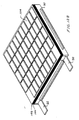
- FIG. 1 is a drawing of the egg-crate and FIG. 2 is a cross sectional drawing of a portion of the egg-crate showing how the P-legs and N-legs are connected in series in the egg-crate.
- the curved arrows e show the direction of electron flow through bottom conductors 2, N legs 4, top conductors 6, and P legs 8 in this portion 10 of the module. Insulating walls 14 keep the electrons flowing in the desired series circuit.
- Bi 2 Te 3 thermoelectric modules that are available at Hi-Z are designed to produce 2.5 watts, 9 watts, 14 watts and 20 watts at the 200°C temperature differential.
- bismuth telluride is often used to refer to all combinations of Bi 2 Te 3 , Bi 2 Se 3 , Sb 2 Te 3 and Sb 2 Se 3 .
- Bi 2 Te 3 it means any combination of Bi 2 Te 3 , Bi 2 Se 3 , Sb 2 Te 3 and Sb 2 Se 3 .
- the egg-crates for the above described Bi 2 Te 3 modules are injection molded using a thermoplastic supplied by Dupont under the trade name "Zenite". Zenite melts at a temperature of about 350°C. The thermoelectric properties of Bi 2 Te 3 peak at about 100°C and are greatly reduced at about 250°C. For both of these reasons, uses of these modules are limited to applications where the hot side temperatures are lower than about 250°C.
- thermoelectric materials are available. These include bismuth telluride, lead telluride, silicon germanium, silicon carbide, boron carbide and many others. In these materials relative abundance can make huge differences in the thermoelectric properties. Much experimental data regarding these materials and their properties is available in the thermoelectric literature such as the CRC Handbook referenced above. Each of these materials is rated by their "figure of merit" which in all cases is very temperature dependent. Despite the fact that there exists a great need for non-polluting electric power and the fact that there exists a very wide variety of un-tapped heat sources; thermoelectric electric power generation in the United States and other countries is minimal as compared to other sources of electric power.
- thermoelectric efficiencies are typically low compared to other technologies for electric power generation and the cost of thermoelectric systems per watt generated is high relative to other power generating sources. Generally the efficiencies of thermoelectric power generating systems are in the range of about 5 percent.
- Lead telluride thermoelectric modules are also known in the prior art.
- a prior art example is the PbTe thermoelectric module described in US Patent No. 4,611,089 issued many years ago to two of the present inventors.
- That module utilized lead telluride thermoelectric alloys with an excess of lead for the N legs and lead telluride with an excess of tellurium for the P legs.
- the thermoelectric properties of the heavily doped lead telluride thermoelectric alloys peak in the range of about 425 °C.
- the egg-crate for the module described in the above patent was fabricated using a technique similar to the technique used many years ago for making chicken egg crates using cardboard spacers.
- the spacers were mica which was selected for its electrical insulating properties at high temperatures. Mica, however, is marginal in strength and cracks easily. A more rugged egg-crate material is needed.
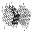
- FIG. 3 is a drawing from the 4,611,089 patent showing a blow-up of the module described in that patent.
- the egg-crate included a first set of parallel spacers 46a to 46k and a second set of spacers 48a to 48i.
- the N legs are shown at 52 and the P legs are shown at 54.
- the module included hot side conductors 56 and cold side conductors 58 to connect the legs in series as in the Bi 2 Te 3 module described above.
- That lead telluride module was suited for operation in temperature ranges in excess of 500°C. But the cost of fabrication of this prior art module is greatly in excess of the bismuth telluride module described above. Also, after a period of operation of about 1000 hours some evaporation of the P legs and the N legs at the hot side would produce cross contamination of all of the legs which would result in degraded performance.
- thermoelectric module designed for operation at hot side temperatures in excess of 500°C preferably with thermoelectric properties substantially in excess of prior art high-temperature thermoelectric modules.
- the present invention provides a long life, low cost, high-temperature, high efficiency thermoelectric module.
- Preferred embodiments include a two-part (a high temperature part and a low temperature part) egg-crate and segmented N legs and P legs.
- the legs are segmented into two or three segments.
- three segments are chosen for their chemical compatibility and/or their figure of merit in the various temperature ranges between the hot side and the cold side of the module.
- the legs include metal meshes partially embedded in thermoelectric segments to help maintain electrical contacts notwithstanding substantial differences in thermal expansions.
- a two-part molded egg-crate holds in place and provides insulation and electrical connections for the thermoelectric N legs and P legs.
- the high temperature part of the egg-crate is comprised of a ceramic material capable of operation at temperatures in excess of 500°C and the low temperature part is comprised of a liquid crystal polymer material having very low thermal conductivity.
- the high temperature ceramic is zirconium oxide and the liquid crystal polymer material is a DuPont Zenite available from DuPont in the form of a liquid crystal polymer resin.
- the module is sealed in an insulating capsule.
- the high and intermediate temperature thermoelectric materials for the N legs are two types of lead telluride thermoelectric material (3N and 2N, respectively) and the low-temperature material is bismuth telluride.
- the high and intermediate temperature materials for the P legs are also lead telluride (3P and 2P, respectively).
- the low temperature material is bismuth telluride.
- low temperature contacts are provided by thermally sprayed molybdenum-aluminum which provides excellent electrical contacts between the N and P legs.
- Iron metal mesh spacers are provided at the hot side to maintain electrical contact notwithstanding substantial thermal expansion variations. These mesh spacers may also be inserted between the lead telluride material and the bismuth telluride and/or between the different types of lead telluride material. These mesh spacers are flexible and maintain good contact and prevent or minimize cracking in the legs despite the expansion and contraction of the legs due to thermal cycling.
- a preferred embodiment is a thermoelectric module with approximately 16 percent conversion efficiency at a hot side temperature of 560 °C and a cold side of 50 °C.
- This module amalgamates numerous recent thermoelectric materials advances achieved by different groups with novel techniques developed by Applicants. This 16 percent efficiency is approximately double the efficiency presently available commercially. Adding a recently upgraded Bi 2 Te 3 cold side segment to the PbTe legs increases the module efficiency by about 3 percentage points from about 8 percent as described in the background section to about 11 percent. An additional 5 digit increase in efficiency can be achieved by applying nano-grained technology as described below.
- the thermoelectric legs of preferred embodiments are fabricated using low-cost powder metallurgy. Segmented prefabricated legs may be bonded using a spot welding technique.
- the resultant cold side contact is firmly bonded to the legs and eliminates the need for numerous individual components.
- molybdenum and aluminum zinc may also be used.
- Applicants have embedded iron mesh contacts into the PbTe to make a compliant thermal and electrical connection to an iron connector. This has several advantages. By embedding an iron mesh (or other compatible material) into PbTe the surface area of the contact can be much larger than the simple prior art planar contact of an iron shoe. In addition to the larger contact area, an embedded contact is held in place by mechanical forces as well as a metallurgical bond. The iron mesh is spot welded to the iron shoe. These metal meshes permit the modules to be utilized without the normally required compression between the hot and cold surfaces.
- P-type PbTe alloys known to Applicants are slightly tellurium excess.
- the excess Te acts as a P-type dopant.
- Te excess alloys however are not compatible with iron and are more reactive and volatile than PbTe alloys with excess tin and/or manganese. For these reasons in preferred embodiments the hot side segment in contact with the Fe shoe will contain a PbSnMnTe or PbSnTe alloy with a deficiency or no excess of tellurium.
- Nano-sized materials have a large number of grain boundaries that impede the propagation of phonons through the material resulting in reduced thermal conductivity and increased ZT.
- an inert fine material is added to the alloy that is in the form of nano-sized particulates. The fine additive results in prevention of grain growth and also impedes phonon propagation. This technique has been used with P type Bi 2 Te 3 alloys. Applicants have demonstrated that similar reductions in thermal conductivity can be achievable in PbTe by fabricating it with nano-sized grains. Nano-sized grains can be achieved by ball milling, mechanical alloying, chemical processing and other techniques.
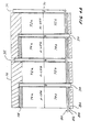
- FIGS. 4 , 4A and 7 A first preferred embodiment of the present invention can be described by reference to FIGS. 4 , 4A and 7 .
- the FIGS. 4 and 4A drawings are from the parent application Serial No. 12/317,170 , but this first preferred module is substantially improved and more efficient version than the embodiment described in parent patent application.
- the first preferred embodiment in this application utilizes three-segment thermoelectric legs in the module instead of only two.
- segments 72a and 74a as shown in FIGS. 4 and 4A are each comprised of two types of lead telluride material instead of only one type as in the parent application.
- This preferred embodiment is shown more specifically in FIG. 7 where the two types of lead telluride material in each leg are clearly shown. Details regarding the legs are provided below in the section entitled "Three Segment Thermoelectric Legs".
- Egg-crate 70 is injection molded using a technique similar to that described in Patent No. 5,875,098. However, the molding process in substantially more complicated.
- the egg-crate comes in two molded together sections. It includes a high temperature section (which will lie adjacent to a hot side) molded from stabilized zirconium oxide (ZrO 2 ). ZrO 2 has a very high melting point of 2715°C and a very low thermal conductivity for an oxide.
- the egg-crate also includes a lower temperature section (which will lie adjacent to a cold side) molded from Zenite Model 7130 available from DuPont that has a melting point of 350°C and has a very low thermal conductivity.
- the ZrO 2 portion of the egg-crate is fabricated by injection molding of the ZrO 2 powders with two different binder materials. Some of the binder material is removed by leaching prior to sintering. The ZrO 2 portion is then sintered to remove the second binder and produce a part with good density and high temperature strength. The ZrO 2 portion will typically shrink about 20 percent during sintering. This sintered section is then placed in a second mold and a subsequent injection molding of the Zenite portion of the egg-crate is then performed, thereby bonding the Zenite to the ZrO 2 .
- FIG. 4A shows a preferred technique for assuring a good bond between the ZrO 2 portion and the Zenite portion.
- a tab shown at 30 is molded at the bottom of the ZrO 2 walls 32. This increases the bonding surface between the ZrO 2 portion 32 and the Zenite portion 34 of the egg-crate walls.
- Lead Telluride thermoelectric alloys allow thermoelectric modules to operate at higher temperatures than do modules based on bismuth telluride alloys and so have the potential to be much more efficient than bismuth telluride modules. Unlike bismuth telluride however, lead telluride is less ductile and cracks more readily than does bismuth telluride. This makes it difficult to build a bonded module and so most lead telluride modules are made by assembling many individual components that are subsequently held in compression with pressures as high as 6894757 pascal (1,000 psi). The high compressive force allows a bond to form between the lead telluride and the contact materials but these bonds break if the module is thermally cycled.
- the present invention provides a method of forming permanent bonds on both the hot and cold side of the module which eliminates the need for high compressive forces and permits thermally cycling without the substantial risk of breakage.
- This method includes the use in the legs of a mesh of conducting material such as an iron mesh. Details are provided in the sections that follow.
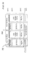
- FIG. 7 Important features of this first preferred embodiment of the present invention are shown in FIG. 7 .
- the egg-crate is very similar to the one shown in FIGS. 4 and 4A .
- An important difference as indicated above is that the high-temperature thermoelectric material portion of the N legs are 3N and 2N lead telluride materials and 3P and 2P for the P legs as shown in FIG. 7 instead of only one type of lead telluride material.
- the designation 3N and 2N refer to PbTe doped for higher temperature operation and for lower temperature operation respectively.
- the designation 3P is for PbSnMnTe and 2P is for PbTe. While 2P doped with Na initially is better performing, it degrades due to Te vaporization.
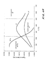
- FIGS. 6A and 6B illustrate, respectively for N and P PbTe legs, how the figure of merit for these alloys change as a function of temperature.
- Bismuth telluride works best below about 250 °C.
- Bismuth telluride thermoelectric material is available form Marlow Industries with offices in Dallas, TX.
- Several successful methods are available for fabrication of PbTe materials and are described in " Lead Telluride Alloys and Junctions" of Thermoelectric Materials and Devices, Cadoff and Miller, published by Reinhold Publishing Corporation of New York .
- the bismuth telluride segments 72b and 74b are respectively doped with 0.1 Mol percent iodoform (CHI 3 ) to create the lower temperature N-type material and 0.1 part per million Pb to create lower temperature P-type material.
- CHI 3 0.1 Mol percent iodoform
- thermoelectric legs for the second version of the first preferred embodiment is straight forward.
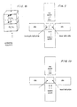
- P type Bi 2 Te 3 powder can be simply cold pressed simultaneously with the lead telluride powders as shown in FIG. 8 and then sintered.
- the PbTe portion shown in FIG. 8 is 3P type and 2P type PbTe on top and Bi 2 Te 3 at the bottom (colder side) of the leg.
- the thermoelectric properties for P type Bi 2 Te 3 material are isotropic and so they are independent of the pressing direction. Segmenting N type Bi 2 Te 3 material with PbTe elements is much more difficult because the thermoelectric properties for N type Bi 2 Te 3 is anisotropic and the best properties are perpendicular to the pressing direction.
- This method consists of the following steps:
- N type Bi 2 Te 3 grains become oriented in the plane perpendicular to the pressing direction.
- the leg must be used so that the temperature gradient is perpendicular to the pressing direction of the element was pressed in. While this is simple to do with an unsegmented leg it is difficult to do this with a segmented leg because the powders from the two segments will tend to mix in the die and an accurate segment line will be difficult to achieve.
- the proposed method consists of pressing the two segments into low density blocks that contain the proper amount of material for the desired final segments and then inserting these pre-pressed blocks into a die that will be subsequently pressed perpendicular to the expected temperature gradient.
- the Bi 2 Te 3 segment and the PbTe segment may be two separate pieces as shown in FIG. 9 or a single piece as shown in FIG. 10 and as described below:
- Steps 2, 3 and 4 can be replaced with a spot welding procedure.
- An Fe mesh or PbTe power may also be placed between the thermoelectric PbTe and BiTe segments and then spot welded in a process similar to spark sintering. In this process a current is sent through the segments and then the purposely placed interfacing resistance preferentially heats up and forms a low contact resistance point. The process time is less than one second.
- FIGS. 4A and 7A and 7B Other module components are shown in FIGS. 4A and 7A and 7B in two variation of this first preferred embodiment.
- FIG. 7 The variation shown in FIG. 7 is similar to the one shown in FIG. 4A .
- hot conductor 76 comprised of iron metal.
- Below hot conductor 76 are an N Leg 72 and a P leg 74.
- the 3P portion of 74a of P leg 74 is in contact with iron conductor 76 and the 3N protion of leg 72a of N leg 72 is also in contact with the iron conductor 76.
- a graphite spacer 78 is not needed in this embodiment since the 3P segment 74a is compatable with iron as explained above.
- This module includes iron mesh compliant interface 75 that provides an electrically conductive interface between the PbTe interface and the iron hot shoe and also permits expansion and contraction of the N and P legs.
- the cold conductor is zinc which is thermal sprayed onto the bottom of the module to rigidly fix the bottom of the N legs 72 and the P legs 74 to the structure of the egg-crate.
- the Pb compatibility foil 80 shown in FIG. 4 is not needed.
- FIG. 7A A second preferred embodiment of the present invention is shown in FIG. 7A .
- This embodiment is similar to the FIG. 7 embodiment. It combines the above techniques with existing state of the art materials to produce a cost effective thermoelectric module with an accumulated efficiency of 16 percent when operated between a hot side temperature of about 560 °C and 50 °C. The stack-up of improved efficiencies is shown in Table I. Commercially available PbTe materials can provide modules with efficiencies of 7 percent with the above temperature difference. In this preferred embodiment Applicants increase the efficiency to 9 percent by adding a P-type Bi 2 Te 3 cold segment and further increase the efficiency to 10 percent by adding an N-type cold segment using a new Bi 2 Te 3 material developed by Applicants.
- the efficiency is further increased to 11 percent by dividing the PbTe material into two segments, i.e. 2P and 3P.
- An improved PbTe material is used to gain another incremental improvement in efficiency to 12 percent as described in US patent application Serial No. 12/293,170 .
- a second technique used by Applicants is to add a thin layer of PbSnMnTe at the top (hot side) of the p-legs (not shown in the drawings).
- This material is labeled 3P in FIGS. 7 and 7A .
- Applicants have determined that elemental tellurium exhibits little or no evaporation from PbSnMnTe. While the PbSnMnTe material does not have as good thermoelectric properties as PbTe, the amount used is small, only 0.51 millimeter (0.020 inch) long out of 11.43 millimeters (0.450 inch) overall length.
- the PbSnMnTe segments will be cold pressed and sintered with the 2P type PbTe and Bi 2 Te 3 as shown in FIGS 7 and 7A .
- the PbSnMnTe material may be substituted for the hot portion of the p-legs.
- thermoelectric module of preferred embodiments will typically be placed between a hot surface of about 600°C and a cold surface of about 50°C. In many applications these temperatures may vary widely with temperature differentials swinging from 0°C to 550°C. Therefore the module and its components should be able to withstand these temperatures and these changes in temperature which will produce huge stresses on the module and its components. Both of the above versions of this embodiment is designed to meet these challenges.
- FIGS. 4A include a fiber metal compliant felt pad comprised of iron, copper or bronze wool.
- the fiber metal mesh material is located at the bottom (cold side) of the module.
- the fiber mesh material is located at the top (hot side) of the module.
- the fiber metal mesh pads can be impregnated with an elastomer such as silicone rubber to reduce the risk of creep and to add deflection and compliance. Silicone rubber can operate at temperatures up to 300 °C. In the second version portions of the mesh will become embedded in the lead telluride material to enhance electrical conductivity.
- an elastomer such as silicone rubber to reduce the risk of creep and to add deflection and compliance. Silicone rubber can operate at temperatures up to 300 °C.
- portions of the mesh will become embedded in the lead telluride material to enhance electrical conductivity.
- Solid iron hot shoes are formed that are sized appropriately to connect the hot side of the P leg to the hot side of the N leg.
- Tellurium excess formulations available in the industry such as 2P will react with iron.
- a suitable PbTe formulation is an alloy of PbTe and SnTe. MnTe may or may not be added.
- One example of a suitable P type element to contact the iron shoe is a thin hot side segment of 3P (a combination of PbTe, MnTe and SnTe), a segment of 2P (Te excess PbTe) below the 3P segment as shown in FIG. 7A and a cold side segment of Bi 2 Te 3 below the 2P segment.
- the spot weld area is minimal but allows the mesh to be flexible during thermal cycling and electrically conductive.
- the purpose of the spot weld is to aid in assembly and to provide a good electrical path from the mesh to the hot contact.
- the hot shoes are then positioned on top of the lead telluride elements that are in the egg-crate as shown in FIGS. 7 and 7A .
- the hot side of the module is then heated in an inert atmosphere to 600°C and then a load is gradually applied.
- the load is slowly increased until a pressure of about 6894757 pascal (1,000 psi) is reached.
- the mesh will slowly embed into the PbTe and form an intimate bond. Because the mesh is free to move slightly with respect to the hot shoes the bond will experience minimal stress and will not break upon thermal cycling. The need for high pressure and high temperature joining can be eliminated if the spot welding bond is used.
- the module is specifically designed to endure considerable thermal cycling or steady state behavior.
- the hot and cold side joints are free to slide and relieve thermal stresses. If the spot welded bonding method is not used the module initially needs to be held in compression at approximately 6894757 pascal (1,000 psi) after it reaches its design operating temperatures so the thermoelectric materials can creep into the Fe mesh. Once this "seat-in” operation is complete the module is well suited for reduced compression at about 344738 - 689476 pascal (50 - 100 psi) to ensure good heat transfer.
- the finished module is also well suited for "radiation coupled" heat sources with minimal or no mechanical connection to the module is made.
- Lead telluride based alloys have been used since the 1960s and the alloys and recommended doping levels were documented above. Their thermoelectric properties versus temperature are given in many publications such as Chapter 10, "Lead Telluride Alloys and Junctions" of Thermoelectric Materials and Devices, Cadoff and Miller, published by Reinhold Publishing Corporation of New York .
- Applicants are seeking to prepare bulk lead telluride thermoelectric material with a finer grain size than has previously been achieved. Fine grain size is expected to lower the thermal conductivity of the material without significant impact on resistivity or Seebeck coefficient, thus raising its ZT and efficiency. In previous attempts others have made to produce a fine-grained PbTe, the grain size was observed to coarsen rapidly, even near room temperature, so the benefit of small grain size could not be retained. In this study, Applicants seek to preserve a fine grain structure by additions of very fine alumina powder, which is expected to produce a grain boundary pinning effect, thus stabilizing the fine grain size. Applicants' recent results indicate that the PbTe grain size can indeed be held below 2 ⁇ m, even with processing at 800°C.
- the techniques described herein can be utilized in modules where the entire legs are comprised of only lead telluride thermoelectric alloys.
- the lead telluride alloy or alloys are one or more of the newer very high efficient alloys.
- the high-temperature module of the preferred embodiment requires encapsulation to prevent oxidation of the N and P alloys with an accompanying decrease in thermoelectric properties.
- An example of encapsulating PbTe modules would be the 1 kW generator for diesel trucks shown at 16 in FIG. 5 since all of the modules are encapsulated together encapsulation of the individual modules is not necessary.
- the generator is attached to a 12.7centimeters(5-inch) diameter exhaust pipe 18.
- Lead telluride thermoelectric modules 20 are mounted on a support structure 22 which is machined to form an octagon.
- the inside surface is generally round with fins (not shown) which protrude into the gas stream to provide a greater heat transfer area.
- the basic design is similar to the design described in US Patent Number 5,625,245 .
- the casting of the support structure has two flanges 24 and 26, one large and one small which are perpendicular to the main part of the support structure.
- the large flange 24 is about 0.25 meter (10 inches) in diameter while the small flange 26 is about 0.20 meter (8 inches) in diameter.
- the large flange contains feed-throughs for both the two electrical connections and four water connections.
- the two electric feed-throughs 28 are electrically isolated with alumina insulators from the support structure.
- Both the large and small flange will contain a weld preparation so a metal dust cover 30 can be welded in position.
- the four water feed-through elements 32 consists of one inch diameter tubes that are welded into the flange.
- the inside portion of the water tubes are welded to a wire reinforced metal bellows hose with the other end connected to the heat sink by a compression fitting or a stainless to aluminum bimetallic joint.
- Two of the tubes are inlets and the other two tubes are outlets for the cooling water.
- the interior volume will be evacuated and back filled with an inert gas such as Argon through a small 9.53 millimeter (3/8 inch) diameter tube 36 in the dust cover to about 75% of one atmosphere when at normal room temperature ( ⁇ 20°c). Once filled, the fill tube will be pinched off and welded.
- an inert gas such as Argon
- thermoelectric modules 20 of the first preferred embodiment are mounted on each of the eight sides of the hexagonal structure for a total of 96 modules.
- FIG. 5A shows such a technique. This is an example where the module is encapsulated in a thin metal capsule which is comprised of a bottom plate 110 and a cover 112. The two parts are welded at the seam. The metal capsule requires a thin insulating sheet on both the hot side and the cold side. Capslues can also be formed with insulating material such as SiO 2 .
- FIGS. 11A , B, C and D describe a technique for making the thermoelectric of the present invention by molding the egg-crate with the thermoelectric legs in place.
- Thermoelectric egg-crates serve several functions. They hold the elements in the correct location, define the pattern of the cold side connectors and locates the hot side connectors. Egg-crates can be assembled from mica as described in US Patent Number 4611089 , injection molded plastic as described in patent (gapless egg-crate) as described in US Patent Number 5,875,098 or injection molded ceramic or injection molded plastic and ceramic as described in parent application Serial No. 12/317,170 . An alternative method of fabricating the egg-crate is proposed below:
- a high temperature mold material could be used for the hot side of the module and a low thermal conductivity material could be used for the cold side as suggested by the dashed line in FIG. 11D .
- a two part egg-crate with the cold side being a polymer/organic based material for strength and the hot side being a ceramic based material for high temperature resistance would be the best choice.
- FIGS. 12A and 12B show features of this composite egg-crate module.
- FIG. 12A is an exploded view of the module and FIG. 12B show the completed module, prior to it being sealed.
- the thermoplastic molded egg-crate is shown at 90. Copper leads are shown at 92 and copper anchor spacers are shown at 94.
- the zinc cold side contacts (which are thermal sprayed and lapped down are shown at 96.
- the ninety six thermoelectric legs are shown at 98. As explained above the bottom parts of the legs are contained within the walls of the thermoplastic egg-crate and the top part of the legs extend above the walls of the egg-crate. Five thin checkerboard mica spacers with ninety six square holes for each of the ninety six legs are shown stacked closely on each other at 100.
- spacers together have a thickness equal to the length of the legs extending above the walls of the thermoplastic egg-crate portion of the module.
- Another five mica spacers are shown at 102.
- These spacers have 48 rectangular holes to fit around the hot side iron shoes which are shown at 104.
- One of these shoes are shown at 104A along with two legs poking up in the drawing to demonstrate how the iron shoes connect the N and P legs at the hot side.
- Iron mesh is spot welded to the iron shoes and partially diffuses into the legs as described above, but the mesh is not shown in the drawing.
- the completed module except for its encapsulation is shown in FIG. 12B .
- Module width 6.0 cm Module depth 7.5 cm Module thickness 1.0 cm Hot side temperature 560 °C Cold side Temperature 50 °C
- 40 P type legs - each P leg is 6.3 mm long, 5.7 mm wide and 5.7 mm deep.
- the bottom (cold side) 2.2 mm is bismuth telluride and the top 1 mm is 3P.
- 40 N type legs - each N leg is 6.3 mm long, 5.7 mm wide and 5.7 mm deep.
- the bottom (cold side) 1.6 mm is bismuth telluride and the top 1.3 mm is 3P.
- thermoelectric alloys Knowing the thermal conductivity of the thermoelectric alloys and how it changes with temperature gradient along the length of the leg is calculated and the segment line for each thermoelectric alloy is positioned as indicated in FIG. 6A and 6B .
- the Bi 2 Te 3 segment on the N leg would be positioned so that its center is at 200 °C.
- the 3N segment on the hot side on the N leg should be positioned so that its center is at 420 °C.
- the 3P segment on the hot side of the P leg is there to be compatible with the iron shoe and avoid Te vaporization so it should be made as thin as possible and still form a reliable separation between the 2P material and the iron shoe.
- thickness is about 1 mm.
- Performance specifications are as follows: Power 40 watts Open circuit voltage 9.6 volts Voltage at matched load 4.8 volts Internal resistance 0.57 ohms Heat flux 9.4 W/cm2 Efficiency (max) 10%
- thermoelectric alloys that are attractive over high-temperature ranges are:
- the egg-crates of the present invention could be utilized with thin film quantum well thermoelectric P and N legs of the type described in detail in US Patent No. 5,550,387 .
- That patent describes N and P thermoelectric legs that are fabricated using alternating layers 10 nanometers thick of Si/Si 0.8 Ge 0.2 layers grown on silicon substrates. In applications with temperatures above 500°C these legs would be used on the cold side.
- That patent and patent 6,828,579 also disclose high temperature lattices comprised of thin layers of B 4 C/B 9 C and Si/SiC can be operated at very high temperatures up to about 1100°C. Details for fabricating B 4 C/B 9 C thermoelectric legs are provided in US Patent No. 6,828,579 (assigned to Applicants' employer). See especially Col.
- thermoelectric legs which could be used in the egg-crate of the present invention or on the hot side of the legs along with bismuth telluride or quantum well Si/SiGe for the cold side.
- a large number of 10 nm quantum well layers are built up on a compatible substrate that has a low thermal conductivity to produce quantum well thermoelectric film.
- Kapton is a good substitute candidate if the temperature is not too high.
- silicon is a preferred choice of substrate material as described in Col. 11 of Patent No. 6,828,579 .
- Other substrate materials are discussed in Col. 7.
- a good substrate material not disclosed in the patent is porous silicon. Porous silicon can survive very high temperatures and has extremely low thermal conductivity.
- the pores can be produced in silicon film such as 5 micron thick film from one side to extend to within a fraction of a micron of the other side. The pores can be produced either before the thermoelectric layers are laid down or after they are laid down.
- the quantum well thermoelectric film is cut and combined to make n and p type legs of the appropriate size and each leg is loaded into one opening of the FIG. 4 egg-crate.
- n and p type legs of the appropriate size and each leg is loaded into one opening of the FIG. 4 egg-crate.
- electrical contacting materials of Pb foil and Cu connecting straps are then assembled followed by the Al 2 O 3 spacer and Cu felt.
- the module is then turned over and the graphite piece is placed against the P leg, followed by the iron conductor strap which contacts the graphite and the N type PbTe.
- the PbTe portions of the p-legs can also be cold pressed and sintered separately from the Bi 2 Te 3 portions. When they are subject to hot operating conditions they will diffusion bond. The same applies to the n-legs.
- thermoelectric materials are hot press the thermoelectric materials in bulk then slice and dice them into legs.
- an aerogel material is used to fill all unoccupied spaces in the egg-crate.
- a module assembly will be sent to an aerogel fabrication laboratory. They will immerse it in silica sol immediately after dropping the pH of the sol. The sol converts to silica gel over the next few days. It is then subjected to a supercritical drying process of tightly controlled temperature and pressure condition in a bath of supercritical liquid CO 2 . This process removes all the water in the gel and replaces it with gaseous CO 2 .
- the Aerogel serves multiple functions: (1) helping to hold the module together, (2) reducing the sublimation rate of the PbTe and (3) providing thermal and electrical insulation around the legs.
- an egg-crate made of non-woven refractory oxide fiber material, possibly with a fugitive polymer binder, and having the consistency of stiff paper or card stock is used. After assembly, the binder is burned away, leaving a porous fiber structure that is them infiltrated with Aerogel. The fiber reinforcement of the aerogel gives added strength and toughness.
Landscapes
- Engineering & Computer Science (AREA)
- Manufacturing & Machinery (AREA)
- Chemical & Material Sciences (AREA)
- Inorganic Chemistry (AREA)
- Powder Metallurgy (AREA)
- Cooling Or The Like Of Semiconductors Or Solid State Devices (AREA)
Description
- The present invention relates to thermoelectric modules and especially to high temperature thermoelectric modules.
- The present invention is a continuation-in-part of Serial No.
12/317,170 filed 12/19/2008 - The Seebeck coefficient of a thermoelectric material is defined as the open circuit voltage produced between two points on a conductor, where a uniform temperature difference of 1 K exists between those points.
- The figure-of-merit of a thermoelectric material is defined as:

where α is the Seebeck coefficient of the material, σ is the electrical conductivity of the material and λ is the total thermal conductivity of the material. - A large number of semiconductor materials were being investigated by the late 1950's and early 1960's, several of which emerged with Z values significantly higher than in metals or metal alloys. As expected no single compound semiconductor evolved that exhibited a uniform high figure-of-merit over a wide temperature range, so research focused on developing materials with high figure-of-merit values over relatively narrow temperature ranges. Of the great number of materials investigated, those based on bismuth telluride and lead telluride alloys emerged as the best for operating in various temperature ranges up to 600°C. Much research has been done to improve the thermoelectric properties of the above thermoelectric materials. For example n-type Bi2Te3 typically contains 5 to 15 percent Bi2Se3 and p-type Bi2Te3 typically contains 75 to 80 Mol percent Sb2Te3. Lead telluride is typically doped with Na and Te for P type behavior and Pb and I (iodine) for N type behavior.
- The temperature at which a thermoelectric alloy is most efficient can usually be shifted to higher or lower temperatures by varying the doping levels and additives. Some of the more common variations with PbTe alloys are designated in the thermoelectric industry as 3N and 2N for N type and 2P and 3P for P type. An in depth discussion of PbTe alloys and their respective doping compositions is given in the book edited by Cadoff and Miller,
Chapter 10 "Lead Telluride Alloys and Junctions." For further understanding of Bi2Te3 based alloys and their doping, see two books edited by D.M. Rowe "CRC Handbook of Thermoelectrics, especially Chapter 19 and Thermoelectrics Handbook "Macro to Nano, Chapter 27. In this specification and in the claims the term PbTe is meant to include any lead and telluride semi-conductor alloy when both the lead and telluride Mol percentage is greater than 20 percent. This includes intrinsic or doped N or P type PbTe, PbSnMnTe and PbSnTe alloys, PbTe doped with Thallium, or AgTe2. - Thermoelectric materials can be divided into three categories: low, mid-range and high temperature.
- Commercially available low temperature materials are commonly based on Bi2Te3 alloys. When operated in air these materials can not exceed 250°C on a continuous basis. These alloys are mainly used for cooling although there are a number of waste heat recovery applications based on these alloys. When used as a power source, Bi2Te3 alloys rarely exceed 5% efficiency.
- Mid-range materials are normally based on the use of PbTe & TAGS. PbTe and can operate up to about 560°C and TAGS can operate at about 450 °C. Some Skutterudite based thermoelectric alloys (which are cobalt based alloys) are being investigated that also fall into this category but they exhibit high vaporization rates which must be contained for long life. All mid-range thermoelectric alloys known to Applicants will oxidize in air and must be hermetically sealed. Prior art PbTe alloys rarely exceed about 7 percent efficiency.
- High temperature thermoelectric materials are normally based on SiGe and Zintl alloys and can operate near 1,000 °C. Modules based on these alloys are difficult to fabricate, expensive and are normally used only in space applications. These prior art high temperature materials can achieve as much as 9 percent efficiency in some applications but they are not commercially viable. The reason 9% appears achievable is because of the large temperature difference that can be achieved with these alloys, which in turn increases efficiency.
- A segmented thermoelectric leg preferably utilizes high temperature materials on the hot side of the leg and a low temperature material on the cold side of the legs. This arrangement improves the overall efficiency of the legs.
- Some of the high temperature thermoelectric materials tend to experience high free vaporization rates (such as 50% loss in 300 hours). These modules can be sealed in a metal package referred to as a can. The process is called canning. Alternately, one fabricator has contained the material in Aerogel insulation in an attempt to suppress the evaporation. In another vapor suppression approach the sample was coated with 10 µm of titanium. Metal coatings can contribute to significant electrical and thermal shorting, if they remain un-reacted. Even if reacted, the coatings can still contribute to thermoelectric degradation.
- Electric power generating thermoelectric modules are well known. These modules produce electricity directly from a temperature differential utilizing the thermoelectric effect. The modules include P-type thermoelectric semiconductor elements and N-type thermoelectric semiconductor elements. These thermoelectric elements are called N-legs and P-legs. The effect is that a voltage differential of a few millivolts is created in each leg in the presence of a temperature difference of a few hundred degrees. Since the voltage differential is small, many of these elements (such as about 100 elements) are typically positioned in parallel between a hot surface and a cold surface and are connected electrically in series to produce potentials of a few volts. Thermoelectric modules are well suited to recover energy from a variety of waste heat applications because they are:
• Small • Easily scaled up or down • Solid state • Highly reliable • Silent • Potentially cost effective - For example Hi-Z Technology, Inc., with offices in San Diego California, offers a Model HZ-14 thermoelectric bismuth telluride thermoelectric module designed to produce about 14 watts at a load potential of 1.66 volts with a 200°C temperature differential. Its open circuit potential is 3.5 volts. The module contains 49 N legs and 49 P legs connected electrically in series. It is a 0.5 cm thick square module with 6.27 cm sides. The legs are P-type and N-type bismuth telluride semiconductor legs and are positioned in an egg-crate type structure that insulates the legs from each other except where they are intentionally connected in series at the top and bottom surfaces of the module. That egg-crate structure which has spaces for the 98 legs is described in
US Patent No. 5,875,098 . The egg-crate is injection molded in a process described in detail in the patent. This egg-crate has greatly reduced the fabrication cost of these modules and improved performance for reasons explained in the patent.FIG. 1 is a drawing of the egg-crate andFIG. 2 is a cross sectional drawing of a portion of the egg-crate showing how the P-legs and N-legs are connected in series in the egg-crate. The curved arrows e show the direction of electron flow throughbottom conductors 2, N legs 4,top conductors 6, andP legs 8 in thisportion 10 of the module. Insulating walls 14 keep the electrons flowing in the desired series circuit. Other Bi2Te3 thermoelectric modules that are available at Hi-Z are designed to produce 2.5 watts, 9 watts, 14 watts and 20 watts at the 200°C temperature differential. The term bismuth telluride is often used to refer to all combinations of Bi2Te3, Bi2Se3, Sb2Te3 and Sb2Se3. In this document where the term Bi2Te3 is used, it means any combination of Bi2Te3, Bi2Se3, Sb2Te3 and Sb2Se3. - The egg-crates for the above described Bi2Te3 modules are injection molded using a thermoplastic supplied by Dupont under the trade name "Zenite". Zenite melts at a temperature of about 350°C. The thermoelectric properties of Bi2Te3 peak at about 100°C and are greatly reduced at about 250°C. For both of these reasons, uses of these modules are limited to applications where the hot side temperatures are lower than about 250°C.
- Many different thermoelectric materials are available. These include bismuth telluride, lead telluride, silicon germanium, silicon carbide, boron carbide and many others. In these materials relative abundance can make huge differences in the thermoelectric properties. Much experimental data regarding these materials and their properties is available in the thermoelectric literature such as the CRC Handbook referenced above. Each of these materials is rated by their "figure of merit" which in all cases is very temperature dependent. Despite the fact that there exists a great need for non-polluting electric power and the fact that there exists a very wide variety of un-tapped heat sources; thermoelectric electric power generation in the United States and other countries is minimal as compared to other sources of electric power. The reason primarily is that thermoelectric efficiencies are typically low compared to other technologies for electric power generation and the cost of thermoelectric systems per watt generated is high relative to other power generating sources. Generally the efficiencies of thermoelectric power generating systems are in the range of about 5 percent.
- Lead telluride thermoelectric modules are also known in the prior art. A prior art example is the PbTe thermoelectric module described in
US Patent No. 4,611,089 issued many years ago to two of the present inventors. - That module utilized lead telluride thermoelectric alloys with an excess of lead for the N legs and lead telluride with an excess of tellurium for the P legs. The thermoelectric properties of the heavily doped lead telluride thermoelectric alloys peak in the range of about 425 °C. The egg-crate for the module described in the above patent was fabricated using a technique similar to the technique used many years ago for making chicken egg crates using cardboard spacers. For the thermoelectric egg-crate the spacers were mica which was selected for its electrical insulating properties at high temperatures. Mica, however, is marginal in strength and cracks easily. A more rugged egg-crate material is needed.
-
FIG. 3 is a drawing from the 4,611,089 patent showing a blow-up of the module described in that patent. The egg-crate included a first set of parallel spacers 46a to 46k and a second set of spacers 48a to 48i. The N legs are shown at 52 and the P legs are shown at 54. The module includedhot side conductors 56 andcold side conductors 58 to connect the legs in series as in the Bi2Te3 module described above. - That lead telluride module was suited for operation in temperature ranges in excess of 500°C. But the cost of fabrication of this prior art module is greatly in excess of the bismuth telluride module described above. Also, after a period of operation of about 1000 hours some evaporation of the P legs and the N legs at the hot side would produce cross contamination of all of the legs which would result in degraded performance.
- What is needed is a low cost, high temperature, high efficiency thermoelectric module designed for operation at hot side temperatures in excess of 500°C preferably with thermoelectric properties substantially in excess of prior art high-temperature thermoelectric modules.
- The present invention provides a long life, low cost, high-temperature, high efficiency thermoelectric module. Preferred embodiments include a two-part (a high temperature part and a low temperature part) egg-crate and segmented N legs and P legs. In preferred embodiments the legs are segmented into two or three segments. In preferred embodiments three segments are chosen for their chemical compatibility and/or their figure of merit in the various temperature ranges between the hot side and the cold side of the module. The legs include metal meshes partially embedded in thermoelectric segments to help maintain electrical contacts notwithstanding substantial differences in thermal expansions. In preferred embodiments a two-part molded egg-crate holds in place and provides insulation and electrical connections for the thermoelectric N legs and P legs. The high temperature part of the egg-crate is comprised of a ceramic material capable of operation at temperatures in excess of 500°C and the low temperature part is comprised of a liquid crystal polymer material having very low thermal conductivity. In preferred embodiments the high temperature ceramic is zirconium oxide and the liquid crystal polymer material is a DuPont Zenite available from DuPont in the form of a liquid crystal polymer resin. Preferably the module is sealed in an insulating capsule.
- In preferred embodiments the high and intermediate temperature thermoelectric materials for the N legs are two types of lead telluride thermoelectric material (3N and 2N, respectively) and the low-temperature material is bismuth telluride. The high and intermediate temperature materials for the P legs are also lead telluride (3P and 2P, respectively). And the low temperature material is bismuth telluride. In preferred embodiments low temperature contacts are provided by thermally sprayed molybdenum-aluminum which provides excellent electrical contacts between the N and P legs. Iron metal mesh spacers are provided at the hot side to maintain electrical contact notwithstanding substantial thermal expansion variations. These mesh spacers may also be inserted between the lead telluride material and the bismuth telluride and/or between the different types of lead telluride material. These mesh spacers are flexible and maintain good contact and prevent or minimize cracking in the legs despite the expansion and contraction of the legs due to thermal cycling.
- A preferred embodiment is a thermoelectric module with approximately 16 percent conversion efficiency at a hot side temperature of 560 °C and a cold side of 50 °C. This module amalgamates numerous recent thermoelectric materials advances achieved by different groups with novel techniques developed by Applicants. This 16 percent efficiency is approximately double the efficiency presently available commercially. Adding a recently upgraded Bi2Te3 cold side segment to the PbTe legs increases the module efficiency by about 3 percentage points from about 8 percent as described in the background section to about 11 percent. An additional 5 digit increase in efficiency can be achieved by applying nano-grained technology as described below. The thermoelectric legs of preferred embodiments are fabricated using low-cost powder metallurgy. Segmented prefabricated legs may be bonded using a spot welding technique.
- While adding a Bi2Te3 segment to the P leg is straight forward (PbTe powder is applied on top of Bi2Te3material and the leg is cold pressed and sintered or hot pressed); fabricating a segmented PbTe/Bi2Te3 N-type leg poses a very special challenge because of anisotropy in the electrical conductivity of N-type Bi2Te3. If prepared by powder metallurgical processing, the Bi2Te3 leg will have five times the electrical resistivity in the pressing direction as compared to the resistivity in the direction perpendicular to the pressing direction. This eliminates all the most straight-forward fabrication processes from consideration, such as two layer conventional cold-press and sinter, or conventional diffusion bonding of hot-pressed materials. This is one of the principal reasons why N type PbTe/Bi2Te3 segmented leg technology has never been commercialized. Applicants have identified a processing route that achieves the required control of Bi2Te3 grain orientation while also producing a compatible diffusion bond between segments.
- With a Bi2Te3 segment on the cold side of the PbTe leg it is possible to use Applicants' employer's standard prior art Bi2Te3 contacting methods as described in Patent No.
5,856,200 , especially FIGS. 19A and 19B and related text. - This is a method of forming contacts to Bi2Te3 using thermal spraying of molybdenum and aluminum. The resultant cold side contact is firmly bonded to the legs and eliminates the need for numerous individual components. Instead of molybdenum and aluminum zinc may also be used.
- Applicants have embedded iron mesh contacts into the PbTe to make a compliant thermal and electrical connection to an iron connector. This has several advantages. By embedding an iron mesh (or other compatible material) into PbTe the surface area of the contact can be much larger than the simple prior art planar contact of an iron shoe. In addition to the larger contact area, an embedded contact is held in place by mechanical forces as well as a metallurgical bond. The iron mesh is spot welded to the iron shoe. These metal meshes permit the modules to be utilized without the normally required compression between the hot and cold surfaces.
- The most efficient P-type PbTe alloys known to Applicants are slightly tellurium excess. The excess Te acts as a P-type dopant. Te excess alloys however are not compatible with iron and are more reactive and volatile than PbTe alloys with excess tin and/or manganese. For these reasons in preferred embodiments the hot side segment in contact with the Fe shoe will contain a PbSnMnTe or PbSnTe alloy with a deficiency or no excess of tellurium.
- A significant amount of work has been recently performed to create nano-sized thermoelectric material. Nano-sized materials have a large number of grain boundaries that impede the propagation of phonons through the material resulting in reduced thermal conductivity and increased ZT. To ensure a nano-sized structure, an inert fine material is added to the alloy that is in the form of nano-sized particulates. The fine additive results in prevention of grain growth and also impedes phonon propagation. This technique has been used with P type Bi2Te3 alloys. Applicants have demonstrated that similar reductions in thermal conductivity can be achievable in PbTe by fabricating it with nano-sized grains. Nano-sized grains can be achieved by ball milling, mechanical alloying, chemical processing and other techniques. Applicants have added nano-size alumina powder to nano-sized PbTe powder. These experiments indicated increased efficiencies and successfully inhibited grain growth at 800°C. This approach mimics the commercial oxide dispersion strengthened (ODS) alloys in which the micron sized oxides are added to prevent grain growth, greatly reduces creep and increases strength.
-
-
FIG. 1 is a drawing of a prior art egg-crate for a thermoelectric module. -
FIG. 2 is a drawing of a portion of a module with theFIG. 1 egg-crate. -
FIG. 3 is a prior art blown-up drawing of a prior art lead telluride thermoelectric module. -
FIGS. 4 and4A are drawings showing important features of a preferred embodiment of the present invention. -
FIG. 5 is a drawing showing an application of the preferred embodiment used to generate electricity from the exhaust gas of a truck. -
FIG. 5A shows an encapsulated module. -
FIGS. 6A and6B are graphs showing figures of merit for 2N, 3N, 2P and 3P lead telluride thermoelectric material and N and P bismuth telluride material. -
FIGS. 7 and7A are drawings showing portions of preferred thermoelectric modules. -
FIGS. 8, 9 and 10 show a technique for making hot pressed thermoelectric legs. -
FIGS. 11A , B and C show a molding technique for making modules of the present invention. -
FIG. 12A and12B demonstrate a process for making a preferred thermoelectric module. - A first preferred embodiment of the present invention can be described by reference to
FIGS. 4 ,4A and7 . TheFIGS. 4 and4A drawings are from the parent application Serial No.12/317,170 - For example one significant difference is that the first preferred embodiment in this application utilizes three-segment thermoelectric legs in the module instead of only two. Specifically, for this
preferred embodiment segments 72a and 74a as shown inFIGS. 4 and4A are each comprised of two types of lead telluride material instead of only one type as in the parent application. This preferred embodiment is shown more specifically inFIG. 7 where the two types of lead telluride material in each leg are clearly shown. Details regarding the legs are provided below in the section entitled "Three Segment Thermoelectric Legs". - Egg-
crate 70 is injection molded using a technique similar to that described in Patent No. 5,875,098. However, the molding process in substantially more complicated. The egg-crate comes in two molded together sections. It includes a high temperature section (which will lie adjacent to a hot side) molded from stabilized zirconium oxide (ZrO2). ZrO2 has a very high melting point of 2715°C and a very low thermal conductivity for an oxide. The egg-crate also includes a lower temperature section (which will lie adjacent to a cold side) molded from Zenite Model 7130 available from DuPont that has a melting point of 350°C and has a very low thermal conductivity. - The ZrO2 portion of the egg-crate is fabricated by injection molding of the ZrO2 powders with two different binder materials. Some of the binder material is removed by leaching prior to sintering. The ZrO2 portion is then sintered to remove the second binder and produce a part with good density and high temperature strength. The ZrO2 portion will typically shrink about 20 percent during sintering. This sintered section is then placed in a second mold and a subsequent injection molding of the Zenite portion of the egg-crate is then performed, thereby bonding the Zenite to the ZrO2. While the thermal conductivity of the ZrO2 is among the lowest of any known oxide, its thermal conductivity of 2 W/mK is much higher than the thermal conductivity of Zenite which is 0.27 W/mK. An objective of the present invention is to minimize any loss of heat through the egg-crate material. Also the Zenite is flexible and will allow the two-section egg-crate to endure significant rough handling. The mica of the prior art patent is a relatively weak material that cracks easily.
FIG. 4A shows a preferred technique for assuring a good bond between the ZrO2 portion and the Zenite portion. A tab shown at 30 is molded at the bottom of the ZrO2 walls 32. This increases the bonding surface between the ZrO2 portion 32 and theZenite portion 34 of the egg-crate walls. - Lead Telluride thermoelectric alloys allow thermoelectric modules to operate at higher temperatures than do modules based on bismuth telluride alloys and so have the potential to be much more efficient than bismuth telluride modules. Unlike bismuth telluride however, lead telluride is less ductile and cracks more readily than does bismuth telluride. This makes it difficult to build a bonded module and so most lead telluride modules are made by assembling many individual components that are subsequently held in compression with pressures as high as 6894757 pascal (1,000 psi). The high compressive force allows a bond to form between the lead telluride and the contact materials but these bonds break if the module is thermally cycled. The present invention provides a method of forming permanent bonds on both the hot and cold side of the module which eliminates the need for high compressive forces and permits thermally cycling without the substantial risk of breakage. This method includes the use in the legs of a mesh of conducting material such as an iron mesh. Details are provided in the sections that follow.
- Important features of this first preferred embodiment of the present invention are shown in
FIG. 7 . The egg-crate is very similar to the one shown inFIGS. 4 and4A . An important difference as indicated above is that the high-temperature thermoelectric material portion of the N legs are 3N and 2N lead telluride materials and 3P and 2P for the P legs as shown inFIG. 7 instead of only one type of lead telluride material. Thedesignation designation 3P is for PbSnMnTe and 2P is for PbTe. While 2P doped with Na initially is better performing, it degrades due to Te vaporization. So 3P preferably is used instead because it does not vaporize significantly and can be used with the same Fe hot shoe as the N leg.FIGS. 6A and6B illustrate, respectively for N and P PbTe legs, how the figure of merit for these alloys change as a function of temperature. - Bismuth telluride works best below about 250 °C. Bismuth telluride thermoelectric material is available form Marlow Industries with offices in Dallas, TX. Several successful methods are available for fabrication of PbTe materials and are described in "Lead Telluride Alloys and Junctions" of Thermoelectric Materials and Devices, Cadoff and Miller, published by Reinhold Publishing Corporation of New York. The bismuth telluride segments 72b and 74b are respectively doped with 0.1 Mol percent iodoform (CHI3) to create the lower temperature N-type material and 0.1 part per million Pb to create lower temperature P-type material.
- Making the thermoelectric legs for the second version of the first preferred embodiment is straight forward. P type Bi2Te3 powder can be simply cold pressed simultaneously with the lead telluride powders as shown in
FIG. 8 and then sintered. (Note that the PbTe portion shown inFIG. 8 is 3P type and 2P type PbTe on top and Bi2Te3 at the bottom (colder side) of the leg.) This is because the thermoelectric properties for P type Bi2Te3 material are isotropic and so they are independent of the pressing direction. Segmenting N type Bi2Te3 material with PbTe elements is much more difficult because the thermoelectric properties for N type Bi2Te3 is anisotropic and the best properties are perpendicular to the pressing direction. This means that if an N type thermoelectric element was pressed with PbTe powder on the hot side and Bi2Te3 on the cold side as shown inFIG. 8 , the Bi2Te3 properties in the pressing direction (which is the direction the heat would flow) would be poor. Two methods to fabricate a suitable segmented N type element may be used: 1) press separate and bond and 2) press separate then co-press. These are described below. - This method consists of the following steps:
- 1) Press and sinter the PbTe segment.
- 2) Press and sinter the Bi2Te3 segment.
- 3) Rotate the Bi2Te3 segment so that it's best properties (perpendicular to the pressing direction) are in the correct orientation and insert the segment into a tight fitting die. If the die allows the Bi2Te3 segment to deform an excessive amount, the grains will rotate and the properties will be degraded.
- 4) Insert the PbTe segment so it rests snuggly against the Bi2Te3 segment. It may be useful to use an interface layer to aid in the bonding. One potential interface layer may be SnTe.
- 5) With a small force on the stack up, heat the segments to 400 °C in a reducing atmosphere for 48 hours.
- And alternative to this method would be to:
- 1) Press and sinter the Bi2Te3 segment.
- 2) Rotate the Bi2Te3 segment so that it's best properties (perpendicular to the pressing direction) are in the correct orientation and insert the segment into a tight fitting die. If the die allows the Bi2Te3 segment to deform an excessive amount, the grains will rotate and the electrical properties will be degraded.
- 3) Fill the remainder of the die with PbTe powder. An interface layer such as SnTe may be useful.
- 4) Cold press and sinter the resultant element or the element could be hot pressed.
- During the pressing operation, N type Bi2Te3 grains become oriented in the plane perpendicular to the pressing direction. To make a useful pressed N type Bi2Te3 leg, the leg must be used so that the temperature gradient is perpendicular to the pressing direction of the element was pressed in. While this is simple to do with an unsegmented leg it is difficult to do this with a segmented leg because the powders from the two segments will tend to mix in the die and an accurate segment line will be difficult to achieve. The proposed method consists of pressing the two segments into low density blocks that contain the proper amount of material for the desired final segments and then inserting these pre-pressed blocks into a die that will be subsequently pressed perpendicular to the expected temperature gradient. The Bi2Te3 segment and the PbTe segment may be two separate pieces as shown in
FIG. 9 or a single piece as shown inFIG. 10 and as described below: - 1) Separately cold press the PbTe and the Bi2Te3 segment. The pellet should be low density and each segment should have the proper amount of material for the final leg. The two segments should be of a geometry small enough to fit into the die that will be used for the final press.
- 2) Place the segments (either one piece or two pieces) into a die that has the desired final geometry.
- 3) Press the pellet to the desired density. Because the pellet has a low density and because the die is larger than the pellet, the pellet will under go significant deformation during this second pressing operation. As the Bi2Te3 segment is pressed the movement caused by the punch will cause the Bi2Te3 grains to rotate into the desired orientation and result in optimum properties in the same direction as the intended temperature gradient. The die must be close to the same size as the pellet being pressed or the segment line will be too distorted.
- 4) Sinter the combined segments elements at 500 °C for 48 hours.
-
Steps 2, 3 and 4 can be replaced with a spot welding procedure. An Fe mesh or PbTe power may also be placed between the thermoelectric PbTe and BiTe segments and then spot welded in a process similar to spark sintering. In this process a current is sent through the segments and then the purposely placed interfacing resistance preferentially heats up and forms a low contact resistance point. The process time is less than one second. - Other module components are shown in
FIGS. 4A and7A and7B in two variation of this first preferred embodiment. - The variation shown in
FIG. 7 is similar to the one shown inFIG. 4A . At the top ishot conductor 76 comprised of iron metal. Belowhot conductor 76 are anN Leg 72 and aP leg 74. The 3P portion of 74a ofP leg 74 is in contact withiron conductor 76 and the 3N protion ofleg 72a ofN leg 72 is also in contact with theiron conductor 76. Agraphite spacer 78 is not needed in this embodiment since the 3P segment 74a is compatable with iron as explained above. This module includes iron meshcompliant interface 75 that provides an electrically conductive interface between the PbTe interface and the iron hot shoe and also permits expansion and contraction of the N and P legs. In this version of the first preferred embodiment the cold conductor is zinc which is thermal sprayed onto the bottom of the module to rigidly fix the bottom of theN legs 72 and theP legs 74 to the structure of the egg-crate. ThePb compatibility foil 80 shown inFIG. 4 is not needed. - A second preferred embodiment of the present invention is shown in
FIG. 7A . This embodiment is similar to theFIG. 7 embodiment. It combines the above techniques with existing state of the art materials to produce a cost effective thermoelectric module with an accumulated efficiency of 16 percent when operated between a hot side temperature of about 560 °C and 50 °C. The stack-up of improved efficiencies is shown in Table I. Commercially available PbTe materials can provide modules with efficiencies of 7 percent with the above temperature difference. In this preferred embodiment Applicants increase the efficiency to 9 percent by adding a P-type Bi2 Te3 cold segment and further increase the efficiency to 10 percent by adding an N-type cold segment using a new Bi2Te3 material developed by Applicants. The efficiency is further increased to 11 percent by dividing the PbTe material into two segments, i.e. 2P and 3P. An improved PbTe material is used to gain another incremental improvement in efficiency to 12 percent as described inUS patent application Serial No. 12/293,170 . - Utilizing nano-grained Bi2Te3 available from GMZ Inc., with offices in West Chester, Ohio, provides another 1.0 percent to increase the accumulated efficiency to 13 percent and finally an additional 3 percent improvement is provided by use of nano-grained PbTe material to provide a module that operates at efficiencies of about 16 percent.
Table 1 - Approaches to Improving Module Efficiency Approach Technology status Digit Increase in efficiency Accum. Efficiency Commercially available PbTe Hi-Z fabricates --- 7% P type Bi2Te3 cold segment existing 2% 9% N type Bi2Te3 cold segment new 1% 10% 2P with 3P hot segment new/existing 1 % 11% Vendor X, N type PbTe new 1% 12% Nanograined Bi2Te3 from GMZ Inc. existing 1% 13% Nanograined PbTe legs new 3% 16% - As indicated in the background section life testing by Applicants of PbTe modules has shown that some degradation of the module occurs after approximately 1,000 hours of operation. Applicants have discovered that the degradation can be attributed to "crosstalk" between the N legs and the P legs near the hot junction caused by evaporation of tellurium from the P leg contaminating the N-leg. (As explained in the background section an excess of lead in the n-leg is what provides the n-leg with its thermoelectric doping properties.) The problem is prevented in preferred embodiments with two techniques: First, as shown in
FIG. 4 the egg-crate walls separating the N legs from the P legs may be extended to contact thehot conductor 76 so that tellurium vapor is restrained from migrating to the n-leg. A second technique used by Applicants is to add a thin layer of PbSnMnTe at the top (hot side) of the p-legs (not shown in the drawings). This material is labeled 3P inFIGS. 7 and7A . Applicants have determined that elemental tellurium exhibits little or no evaporation from PbSnMnTe. While the PbSnMnTe material does not have as good thermoelectric properties as PbTe, the amount used is small, only 0.51 millimeter (0.020 inch) long out of 11.43 millimeters (0.450 inch) overall length. The PbSnMnTe segments will be cold pressed and sintered with the 2P type PbTe and Bi2Te3 as shown inFIGS 7 and7A . In some embodiments the PbSnMnTe material may be substituted for the hot portion of the p-legs. - The thermoelectric module of preferred embodiments will typically be placed between a hot surface of about 600°C and a cold surface of about 50°C. In many applications these temperatures may vary widely with temperature differentials swinging from 0°C to 550°C. Therefore the module and its components should be able to withstand these temperatures and these changes in temperature which will produce huge stresses on the module and its components. Both of the above versions of this embodiment is designed to meet these challenges.
- Preferred embodiments shown in
FIGS. 4A include a fiber metal compliant felt pad comprised of iron, copper or bronze wool. In the first version as shown at 86 inFIG. 4A the fiber metal mesh material is located at the bottom (cold side) of the module. For the embodiments shown inFIGS. 7 and7A as shown at 75 the fiber mesh material is located at the top (hot side) of the module. These materials provide good thermal conductivity and are able to deform when the module is placed in compression between the heat source and heat sink. These materials are resilient to respond to thermal cycling and to the inevitable warping that the module will undergo because of the thermal gradient imposed across it. These compliant materials are also able to cushion the brittle lead telluride yet maintain intimate contact between it and the heat sinks. For the first version the fiber metal mesh pads can be impregnated with an elastomer such as silicone rubber to reduce the risk of creep and to add deflection and compliance. Silicone rubber can operate at temperatures up to 300 °C. In the second version portions of the mesh will become embedded in the lead telluride material to enhance electrical conductivity. - After being put in service the N and P type PbTe legs are creeping or pushing up towards the Fe hot shoe. A load of 6894757 pascal (1,000 psi) is initially used and can be reduced to 3447379 pascal (500 psi) after the module is operated for approximately 100 hours and proper seating of the module is obtained. After this time a lower load of 344738 to 689476 pascal (50 to 100 psi) used to maintain the low contact resistance joints. The same spot welding technique diesribed above can be applied to joining the Fe shoe/mesh to PbTe.
- Solid iron hot shoes are formed that are sized appropriately to connect the hot side of the P leg to the hot side of the N leg. Tellurium excess formulations available in the industry such as 2P will react with iron. A suitable PbTe formulation is an alloy of PbTe and SnTe. MnTe may or may not be added. One example of a suitable P type element to contact the iron shoe is a thin hot side segment of 3P (a combination of PbTe, MnTe and SnTe), a segment of 2P (Te excess PbTe) below the 3P segment as shown in
FIG. 7A and a cold side segment of Bi2Te3 below the 2P segment. To greatly increase the surface area of the hot side connector two layers of iron mesh are spot welded to the iron hot shoe. The spot weld area is minimal but allows the mesh to be flexible during thermal cycling and electrically conductive. The purpose of the spot weld is to aid in assembly and to provide a good electrical path from the mesh to the hot contact. - The hot shoes are then positioned on top of the lead telluride elements that are in the egg-crate as shown in
FIGS. 7 and7A . Keeping the cold side below 300°C the hot side of the module is then heated in an inert atmosphere to 600°C and then a load is gradually applied. The load is slowly increased until a pressure of about 6894757 pascal (1,000 psi) is reached. At this temperature the mesh will slowly embed into the PbTe and form an intimate bond. Because the mesh is free to move slightly with respect to the hot shoes the bond will experience minimal stress and will not break upon thermal cycling. The need for high pressure and high temperature joining can be eliminated if the spot welding bond is used. - The module is specifically designed to endure considerable thermal cycling or steady state behavior. The hot and cold side joints are free to slide and relieve thermal stresses. If the spot welded bonding method is not used the module initially needs to be held in compression at approximately 6894757 pascal (1,000 psi) after it reaches its design operating temperatures so the thermoelectric materials can creep into the Fe mesh. Once this "seat-in" operation is complete the module is well suited for reduced compression at about 344738 - 689476 pascal (50 - 100 psi) to ensure good heat transfer. The finished module is also well suited for "radiation coupled" heat sources with minimal or no mechanical connection to the module is made.
- Lead telluride based alloys have been used since the 1960s and the alloys and recommended doping levels were documented above. Their thermoelectric properties versus temperature are given in many publications such as
Chapter 10, "Lead Telluride Alloys and Junctions" of Thermoelectric Materials and Devices, Cadoff and Miller, published by Reinhold Publishing Corporation of New York - In the past four years newer PbTe based alloys have evolved that have better properties than the conventional PbTe based alloys noted above. For example a July 25, 2008 article in Science Daily reported on a lead telluride material developed at Ohio State University having substantial improvements in efficiency over prior art lead telluride materials. This new material is doped with thallium instead of sodium. The article suggests that the efficiency of the new material may be twice the efficiency of prior art lead telluride. Other experimenters have developed a new N type PbTe which is doped with Ti and iodine and has a ZT of 1.7 (PbTe is typically about 1.0). The P type alloy is Pb7Te3 and doped with AgTe. While it has the same ZT as
PbTe 2P its advantage is that it can be used with Fe hot shoes segmented to Bi2Te3 alloys. - Applicants are seeking to prepare bulk lead telluride thermoelectric material with a finer grain size than has previously been achieved. Fine grain size is expected to lower the thermal conductivity of the material without significant impact on resistivity or Seebeck coefficient, thus raising its ZT and efficiency. In previous attempts others have made to produce a fine-grained PbTe, the grain size was observed to coarsen rapidly, even near room temperature, so the benefit of small grain size could not be retained. In this study, Applicants seek to preserve a fine grain structure by additions of very fine alumina powder, which is expected to produce a grain boundary pinning effect, thus stabilizing the fine grain size. Applicants' recent results indicate that the PbTe grain size can indeed be held below 2 µm, even with processing at 800°C.
- Some of the techniques described herein can be utilized in modules where the entire legs are comprised of only lead telluride thermoelectric alloys. Preferably, the lead telluride alloy or alloys are one or more of the newer very high efficient alloys.
- The high-temperature module of the preferred embodiment requires encapsulation to prevent oxidation of the N and P alloys with an accompanying decrease in thermoelectric properties. An example of encapsulating PbTe modules would be the 1 kW generator for diesel trucks shown at 16 in
FIG. 5 since all of the modules are encapsulated together encapsulation of the individual modules is not necessary. In this example the generator is attached to a 12.7centimeters(5-inch)diameter exhaust pipe 18. Lead telluridethermoelectric modules 20 are mounted on asupport structure 22 which is machined to form an octagon. The inside surface is generally round with fins (not shown) which protrude into the gas stream to provide a greater heat transfer area. The basic design is similar to the design described inUS Patent Number 5,625,245 . - The casting of the support structure has two
flanges 24 and 26, one large and one small which are perpendicular to the main part of the support structure. Thelarge flange 24 is about 0.25 meter (10 inches) in diameter while the small flange 26 is about 0.20 meter (8 inches) in diameter. - The large flange contains feed-throughs for both the two electrical connections and four water connections. The two electric feed-
throughs 28 are electrically isolated with alumina insulators from the support structure. Both the large and small flange will contain a weld preparation so ametal dust cover 30 can be welded in position. - The four water feed-through
elements 32 consists of one inch diameter tubes that are welded into the flange. The inside portion of the water tubes are welded to a wire reinforced metal bellows hose with the other end connected to the heat sink by a compression fitting or a stainless to aluminum bimetallic joint. Two of the tubes are inlets and the other two tubes are outlets for the cooling water. - Once the generator is assembled and the flanges between the support structure and the dust cover are welded as shown at 34, the interior volume will be evacuated and back filled with an inert gas such as Argon through a small 9.53 millimeter (3/8 inch)
diameter tube 36 in the dust cover to about 75% of one atmosphere when at normal room temperature (~ 20°c). Once filled, the fill tube will be pinched off and welded. - In a preferred embodiment nine
thermoelectric modules 20 of the first preferred embodiment are mounted on each of the eight sides of the hexagonal structure for a total of 96 modules. Applicants estimate a total electrical output of about 1.1 kilowatts. This estimate is based on prior performance with the structure described in the 5,625,245 patent, utilizing modules of the first preferred embodiment and assuming an exhaust hot side temperature of about 550 °C and cold side cooling water temperature of about 100 °C. - An alternative to encapsulation the entire generator, as shown in
FIG. 5 , is to encapsulate the individual modules.FIG. 5A shows such a technique. This is an example where the module is encapsulated in a thin metal capsule which is comprised of a bottom plate 110 and a cover 112. The two parts are welded at the seam. The metal capsule requires a thin insulating sheet on both the hot side and the cold side. Capslues can also be formed with insulating material such as SiO2. -
FIGS. 11A , B, C and D describe a technique for making the thermoelectric of the present invention by molding the egg-crate with the thermoelectric legs in place. - Thermoelectric egg-crates serve several functions. They hold the elements in the correct location, define the pattern of the cold side connectors and locates the hot side connectors. Egg-crates can be assembled from mica as described in
US Patent Number 4611089 , injection molded plastic as described in patent (gapless egg-crate) as described inUS Patent Number 5,875,098 or injection molded ceramic or injection molded plastic and ceramic as described in parent application Serial No.12/317,170 - 1) A two-part mold is fabricated from a suitable material. Some possible mold materials are polyethylene, aluminum or Teflon. The mold is designed to hold the thermoelectric elements in place while a mold material is poured around the elements.
- 2) Thermoelectric elements are loaded into the top half of the mold assuring that the N and P elements are located appropriately as shown in
FIG. 11A . - 3) The bottom half of the mold is put in place and castable material is poured into the mold filling the spces labeled "cast material". Several choices are available for suitable castable materials. A two part epoxy would be suitable for low temperature applications. For high temperature applications Aremco's Ceramacast 584 or 645-N would be a good choice.
- 4) After the mold material has cured the part is removed from the mold and would appear as shown in
FIG. 11B . - 5) The cast egg-crate containing the thermoelectric elements is then ready to have the cold side contacts made as described in Patent No.
5,875,098 . The loaded egg-crate is then fixtured appropriately to hold the elements in place while aluminum with a proper Mo bond coat is thermally sprayed onto the cold (bismuth telluride) side of the module. The result is as shown inFIG. 11C at 86. This process is explained in detail in Patent No.4,611,089 . An alternative metal to Mo/Al combination is zinc. - Unlike the gapless egg-crate modules described in Patent No.
5,875,098 , only the cold side of the segmented module is connected in this manner. With the module held firmly to prevent warping, the deposited coating (MoAl or zinc) is sanded to expose the egg-crate walls which thereby define the cold side electrical connectors as described in Patent No.5,875,098 . The module is then lapped to a suitable finish and the bottom (cold side) will appear as shown at 88 inFIG. 11D . Iron shoes provide the electrical connections as shown at 89 inFIG.11D . - Using a slightly different mold design, a high temperature mold material could be used for the hot side of the module and a low thermal conductivity material could be used for the cold side as suggested by the dashed line in
FIG. 11D . Ideally, a two part egg-crate with the cold side being a polymer/organic based material for strength and the hot side being a ceramic based material for high temperature resistance would be the best choice. - Following are techniques for fabricating the module:
- 1. Slice and dice castings of the N and P portions of the PbTe and Bi2Te3 materials. Alternately, fabricate the leg portions by powder metallurgy techniques.
- 2. Join the PbTe and Bi2Te3 portions of the segmented legs by spot welding or plasma spark sintering.
- 3. Assemble legs in a thermoplastic molded egg-crate similar to the prior art egg-crate shown in
FIG. 1 to form a series circuit. - 4. Thermal spray the cold side of the module with Zinc.
- 5. Lap down the Zinc deposit to form a smooth surface and electrically isolate the N and P legs except where they need to be connected. At this point the N and P legs are joined on the cold side and the legs extend out of the egg-crate on the hot side. The top of the eggcrate is expected to operate at less than 250°C.
- 6. To insulate and strengthen the extended N and P legs for use at 560°C, mica layers are stacked up around the extending N and P legs. Between the mica sheets are thin layers of opacified quartz paper. The mica sheets are stacked high enough to contain the Fe shoes. Each of the Fe shoes as described above have two layers of Fe mesh spot welded to the surface that engages the PbTe legs.
- 7. The module is operated at 560°C under compression for several hours to permit the iron mesh to partially bind to the PbTe. This firmly connects the PbTe legs to the iron shoes. The module can then be operated under compression or can be heated by radiation under no compressive load. Alternately, the Fe shoe and mesh can be spot welded to the N and P PbTe legs.
-
FIGS. 12A and12B show features of this composite egg-crate module.FIG. 12A is an exploded view of the module andFIG. 12B show the completed module, prior to it being sealed. The thermoplastic molded egg-crate is shown at 90. Copper leads are shown at 92 and copper anchor spacers are shown at 94. The zinc cold side contacts (which are thermal sprayed and lapped down are shown at 96. The ninety six thermoelectric legs are shown at 98. As explained above the bottom parts of the legs are contained within the walls of the thermoplastic egg-crate and the top part of the legs extend above the walls of the egg-crate. Five thin checkerboard mica spacers with ninety six square holes for each of the ninety six legs are shown stacked closely on each other at 100. These spacers together have a thickness equal to the length of the legs extending above the walls of the thermoplastic egg-crate portion of the module. Another five mica spacers are shown at 102. These spacers have 48 rectangular holes to fit around the hot side iron shoes which are shown at 104. One of these shoes are shown at 104A along with two legs poking up in the drawing to demonstrate how the iron shoes connect the N and P legs at the hot side. Iron mesh is spot welded to the iron shoes and partially diffuses into the legs as described above, but the mesh is not shown in the drawing. The completed module except for its encapsulation is shown inFIG. 12B . - An example of a module that incorporates the features described above will have the following properties:
Module width 6.0 cm Module depth 7.5 cm Module thickness 1.0 cm Hot side temperature 560 °C Cold side Temperature 50 °C - 40 P type legs - each P leg is 6.3 mm long, 5.7 mm wide and 5.7 mm deep. The bottom (cold side) 2.2 mm is bismuth telluride and the top 1 mm is 3P.
40 N type legs - each N leg is 6.3 mm long, 5.7 mm wide and 5.7 mm deep. The bottom (cold side) 1.6 mm is bismuth telluride and the top 1.3 mm is 3P. - Knowing the thermal conductivity of the thermoelectric alloys and how it changes with temperature gradient along the length of the leg is calculated and the segment line for each thermoelectric alloy is positioned as indicated in
FIG. 6A and6B . According to these figures the Bi2Te3 segment on the N leg would be positioned so that its center is at 200 °C. The 3N segment on the hot side on the N leg should be positioned so that its center is at 420 °C. The 3P segment on the hot side of the P leg is there to be compatible with the iron shoe and avoid Te vaporization so it should be made as thin as possible and still form a reliable separation between the 2P material and the iron shoe. Preferably that thickness is about 1 mm. - Performance specifications are as follows:
Power 40 watts Open circuit voltage 9.6 volts Voltage at matched load 4.8 volts Internal resistance 0.57 ohms Heat flux 9.4 W/cm2 Efficiency (max) 10% - While the above description contains many specificities, the reader should not construe these as limitations on the scope of the invention, but merely as exemplifications of preferred embodiments thereof. For example:
- Some of the other thermoelectric alloys that are attractive over high-temperature ranges are:
- Si-20% Ge, LaTe1.4 type alloys
- Zintl, (Yb14MnSb11)
- TAGS (AgSbTe2).15(GeTe).85
- The skutterudites such as CoSb4 type alloys
- The half-Huesler alloys
- All of these bulk alloys and others under development can be used in the new ZrO2/Zenite egg-crate design shown in
Figure 4 or the other eggcrate designs that are described herein. - The egg-crates of the present invention could be utilized with thin film quantum well thermoelectric P and N legs of the type described in detail in
US Patent No. 5,550,387 . That patent describes N and P thermoelectric legs that are fabricated using alternatinglayers 10 nanometers thick of Si/Si0.8Ge0.2 layers grown on silicon substrates. In applications with temperatures above 500°C these legs would be used on the cold side. That patent and patent6,828,579 also disclose high temperature lattices comprised of thin layers of B4C/B9C and Si/SiC can be operated at very high temperatures up to about 1100°C. Details for fabricating B4C/B9C thermoelectric legs are provided inUS Patent No. 6,828,579 (assigned to Applicants' employer). See especially Col. 3 where high temperature performance is discussed. These B4C/B9C and Si/SiC materials could also be used alone to make thermoelectric legs which could be used in the egg-crate of the present invention or on the hot side of the legs along with bismuth telluride or quantum well Si/SiGe for the cold side. - A large number of 10 nm quantum well layers are built up on a compatible substrate that has a low thermal conductivity to produce quantum well thermoelectric film. Kapton is a good substitute candidate if the temperature is not too high. For higher temperature operation silicon is a preferred choice of substrate material as described in Col. 11 of Patent No.
6,828,579 . Other substrate materials are discussed in Col. 7. A good substrate material not disclosed in the patent is porous silicon. Porous silicon can survive very high temperatures and has extremely low thermal conductivity. The pores can be produced in silicon film such as 5 micron thick film from one side to extend to within a fraction of a micron of the other side. The pores can be produced either before the thermoelectric layers are laid down or after they are laid down. - The quantum well thermoelectric film is cut and combined to make n and p type legs of the appropriate size and each leg is loaded into one opening of the
FIG. 4 egg-crate. Before loading the hot and cold ends of the N and P legs are metallized to yield a low contact resistance on the cold side. Electrical contacting materials of Pb foil and Cu connecting straps are then assembled followed by the Al2O3 spacer and Cu felt. The module is then turned over and the graphite piece is placed against the P leg, followed by the iron conductor strap which contacts the graphite and the N type PbTe. - Separate portions of the segmented legs can be readily bonded together by passing a current through both using a spot welding machine sometimes also referred to as spark sintering. As the current passes through the samples, the interface, which is purposely made to have a high resistance, reach a temperature at which bonding takes place. Sometimes a liquid phase is formed. The spot welding time is only a fraction of a second. To form a consistent bond, wire mesh has been used. The mesh preferentially heats up and imbeds itself in both materials. The N type Bi2Te3, which must be used in the correct orientation, retained its crystalline orientation and was successfully bonded to N type PbTe. The contact resistance between the two components was less than 100 µΩ/cm2 and the bond was strong. This bonding technique was also successful for bonding the P leg PbTe and Bi2Te3 segments.
- The PbTe portions of the p-legs can also be cold pressed and sintered separately from the Bi2Te3 portions. When they are subject to hot operating conditions they will diffusion bond. The same applies to the n-legs.
- Another option is to hot press the thermoelectric materials in bulk then slice and dice them into legs.
- In one variation, an aerogel material is used to fill all unoccupied spaces in the egg-crate. A module assembly will be sent to an aerogel fabrication laboratory. They will immerse it in silica sol immediately after dropping the pH of the sol. The sol converts to silica gel over the next few days. It is then subjected to a supercritical drying process of tightly controlled temperature and pressure condition in a bath of supercritical liquid CO2. This process removes all the water in the gel and replaces it with gaseous CO2. The Aerogel serves multiple functions: (1) helping to hold the module together, (2) reducing the sublimation rate of the PbTe and (3) providing thermal and electrical insulation around the legs.
- In another variation, an egg-crate made of non-woven refractory oxide fiber material, possibly with a fugitive polymer binder, and having the consistency of stiff paper or card stock is used. After assembly, the binder is burned away, leaving a porous fiber structure that is them infiltrated with Aerogel. The fiber reinforcement of the aerogel gives added strength and toughness.
Claims (25)
- A high-temperature lead telluride thermoelectric module comprising:A. a two-part egg-crate (70) for holding in place and providing insulation and electrical connections (28, 89) for a number of thermoelectric N-legs (4, 52, 72) and P-legs (8, 54, 74), wherein said egg-crate (70) is comprised of:1) a hot side part comprised of a ceramic material capable of operation at temperatures in excess of 500°C and2) a cold side part comprised of a polymeric material having very low thermal conductivity;B. a plurality of segmented thermoelectric N-legs (4, 52, 72) and P-legs (8, 54, 74), each leg comprised of at least one PbTe segment (72a, 74a) and positioned in said egg-crate (70), at least a portion (10) of said legs being electrically connected in series;
wherein1) each of at least a plurality of said N-legs (4, 52, 72) are comprised ofa) a high-temperature thermoelectric segment (72a, 74a), wherein the high-temperature is in excess of 500°C,b) a low-temperature thermoelectric segment (72b, 74b) andc) at least one metal mesh (75) at least partially embedded in the high-temperature segment (72a, 74a); and2) each of at least a plurality of said P-legs (8, 54, 74) are comprised ofa) a high-temperature thermoelectric segment (72a, 74a), wherein the high-temperature is in in excess of 500°C,b) a low-temperature thermoelectric segment (72b, 74b) andc) at least one metal mesh (75) at least partially embedded in the high-temperature segment (72a, 74a). - The high-temperature lead telluride thermoelectric module as in Claim 1 wherein at least a plurality of said low-temperature thermoelectric segments (72b, 74b) are comprised of BiTe.
- The high-temperature lead telluride thermoelectric module as in Claim 1 wherein each of a plurality of said N-legs (4, 52, 72) also comprises at least one intermediate temperature PbTe segment.
- The high-temperature lead telluride thermoelectric module as in Claim 1 wherein at least one segment of said N-leg (4, 52, 72) and at least one segment of said P-leg (8, 54, 74) is comprised of at least 30 mol percent lead and at least 30 mol percent telluride.
- The high-temperature lead telluride thermoelectric module as in Claim 1 wherein each of a plurality of said P-legs (8, 54, 74) also comprises at least one intermediate temperature PbTe segment.
- The high-temperature lead telluride thermoelectric module as in Claim 2 wherein said plurality of said lead-telluride thermoelectric N-legs (4, 52, 72) and P-legs (8, 54, 74) are electrically connected with one or more metals thermally sprayed on one side of the module defining a cold side.
- The high-temperature lead telluride thermoelectric module as in Claim 6 wherein said one or more metals is zinc.
- The high-temperature lead telluride thermoelectric module as in Claim 6 wherein said one or more metals is molybdenum and aluminum.
- The thermoelectric module as in Claim 1 wherein said ceramic material is zirconium oxide and said polymeric material is in the form of a liquid crystal polymer resin.
- The thermoelectric module as in Claim 1 wherein said ceramic material is comprised of thin stacked sheets of mica.
- The high-temperature lead telluride thermoelectric module as in Claim 1 wherein a plurality of said thermoelectric legs comprise fine micron/nano-sized grains.
- The high-temperature lead telluride thermoelectric module as in Claim 9 wherein the cold side part and the hot side part are joined together at a tab (30) and socket junction.
- The high-temperature lead telluride thermoelectric module as in Claim 1 wherein each N-leg (4, 52, 72) and P-leg (8, 54, 74) of at least a plurality of pairs of said thermoelectric N-legs (4, 52, 72) and P-legs (8, 54, 74) are electrically connected utilizing an iron shoe (89).
- The high-temperature lead telluride thermoelectric module as in Claim 13 wherein each of a plurality of said iron shoes (89) are electrically connected to the pair of N-legs (4, 52, 72) and P-legs (8, 54, 74) with at least two spot-welded metal meshes (75).
- The high-temperature lead telluride thermoelectric module as in Claim 14 wherein said metal meshes (75) are iron meshes.
- The thermoelectric module as in Claim 1 wherein metal meshes (75) are provided in each leg at an interface between segments to maintain proper electrical contacts notwithstanding substantial temperature variations.
- The thermoelectric module as in Claim 15 wherein the metal meshes (75) at the interfaces are impregnated with an elastomer.
- The thermoelectric module as in Claim 17 wherein the elastomer is silicone rubber.
- The high-temperature lead telluride thermoelectric module as in Claim 1 wherein at least a plurality of the segments of said thermoelectric legs are electrically connected to at least one other segment with a metal mesh (75).
- The thermoelectric module as in Claim 1 wherein the module is sealed in an insulating capsule.
- The thermoelectric module as in Claim 1 wherein the module is combined with other similar modules to provide a thermoelectric generator.
- The thermoelectric module as in Claim 13 wherein the thermoelectric generator is adapted to provide electric power from the waste heat of a motor vehicle.
- The thermoelectric module as in Claim 15 wherein the egg-crate (70) walls separating the N-legs (4, 52, 72) from the P-legs (8, 54, 74) are adapted to contact the hot conductor so that tellurium vapor is restrained from migrating to the N-leg (4, 52, 72).
- The thermoelectric module as in Claim 7 wherein at least a plurality of the P-legs (8, 54, 74) comprise a thin layer of PbSnMnTe at their hot sides.
- The thermoelectric module as in Claim 7 wherein at least a plurality of the P-legs (8, 54, 74) comprise a thin layer of SnTe at their hot sides.
Applications Claiming Priority (3)
| Application Number | Priority Date | Filing Date | Title |
|---|---|---|---|
| US12/317,170 US20100024437A1 (en) | 2008-07-29 | 2008-12-19 | High temperature compact thermoelectric module with gapless eggcrate |
| US12/590,653 US20100229911A1 (en) | 2008-12-19 | 2009-11-12 | High temperature, high efficiency thermoelectric module |
| PCT/US2009/067250 WO2010071749A1 (en) | 2008-12-19 | 2009-12-09 | High temperature, high efficiency thermoelectric module |
Publications (3)
| Publication Number | Publication Date |
|---|---|
| EP2377174A1 EP2377174A1 (en) | 2011-10-19 |
| EP2377174A4 EP2377174A4 (en) | 2014-01-15 |
| EP2377174B1 true EP2377174B1 (en) | 2015-04-01 |
Family
ID=42269114
Family Applications (1)
| Application Number | Title | Priority Date | Filing Date |
|---|---|---|---|
| EP09833805.6A Not-in-force EP2377174B1 (en) | 2008-12-19 | 2009-12-09 | High temperature, high efficiency thermoelectric module |
Country Status (6)
| Country | Link |
|---|---|
| US (1) | US20100229911A1 (en) |
| EP (1) | EP2377174B1 (en) |
| KR (1) | KR20110134379A (en) |
| CN (1) | CN102308400A (en) |
| RU (1) | RU2550799C2 (en) |
| WO (1) | WO2010071749A1 (en) |
Families Citing this family (46)
| Publication number | Priority date | Publication date | Assignee | Title |
|---|---|---|---|---|
| US20100024437A1 (en) * | 2008-07-29 | 2010-02-04 | Norbert Elsner | High temperature compact thermoelectric module with gapless eggcrate |
| US8283194B2 (en) * | 2009-07-27 | 2012-10-09 | Basf Se | Method for applying layers onto thermoelectric materials |
| AT508979A1 (en) * | 2009-10-23 | 2011-05-15 | Miba Sinter Austria Gmbh | METHOD FOR PRODUCING A THERMOELECTRIC ELEMENT |
| JP2013510417A (en) * | 2009-11-03 | 2013-03-21 | ビーエーエスエフ ソシエタス・ヨーロピア | Use of porous metal materials as contact connections for thermoelectric modules |
| JP2014500615A (en) * | 2010-10-19 | 2014-01-09 | カリフォルニア インスティテュート オブ テクノロジー | Self-tuning of carrier concentration for high thermoelectric performance |
| DE102011009428A1 (en) | 2011-01-26 | 2012-07-26 | Emitec Gesellschaft Für Emissionstechnologie Mbh | Thermoelectric module with a heat conducting layer |
| JP5640800B2 (en) * | 2011-02-21 | 2014-12-17 | ソニー株式会社 | Wireless power supply apparatus and wireless power supply method |
| DE102011005246A1 (en) * | 2011-03-08 | 2012-09-13 | Behr Gmbh & Co. Kg | Method for producing a thermoelectric module |
| KR101304428B1 (en) * | 2011-08-12 | 2013-09-05 | 국방과학연구소 | Thermoelectric leg, method for manufacturing thereof and thermoelectric module for generation |
| CN103890985A (en) * | 2011-09-16 | 2014-06-25 | 弗诺尼克设备公司 | Low resistivity contact |
| DE102011056877B4 (en) * | 2011-12-22 | 2018-03-29 | Wind Plus Sonne Gmbh | Apparatus and method for direct generation of electrical energy from thermal energy |
| TWI605620B (en) * | 2011-12-30 | 2017-11-11 | 財團法人工業技術研究院 | Thermoelectric module and method of fabricating the same |
| DE102012216042A1 (en) * | 2012-09-11 | 2014-03-13 | Friedrich Boysen Gmbh & Co. Kg | Device for converting thermal energy into electrical energy |
| FR2995983B1 (en) | 2012-09-26 | 2014-10-31 | Commissariat Energie Atomique | HYBRID SOLAR DEVICE FOR GENERATING ELECTRICITY WITH INCREASED LIFETIME |
| WO2014065792A1 (en) * | 2012-10-24 | 2014-05-01 | Hi-Z Technology Inc. | Segmented thermoelectric module with bonded legs |
| WO2014067589A1 (en) * | 2012-11-05 | 2014-05-08 | European Space Agency | Method for manufacturing thermoelectric conversion modules |
| DE102012222679A1 (en) * | 2012-12-10 | 2014-06-12 | Robert Bosch Gmbh | Method for producing a switching module and an associated grid module and an associated grid module and corresponding electronic module |
| CN103022338B (en) * | 2012-12-26 | 2017-05-03 | 中国电子科技集团公司第十八研究所 | Manufacturing method of cascade temperature-difference power generating device |
| CN103078558B (en) * | 2013-01-05 | 2015-04-29 | 浙江大学 | Sandwich flat plate array type-based thermoelectric generator |
| US8927849B2 (en) * | 2013-02-15 | 2015-01-06 | Aleksandr Sergey Kushch | Waste heat thermoelectric generator with auxiliary burner |
| DE102013202785A1 (en) * | 2013-02-20 | 2014-08-21 | Behr Gmbh & Co. Kg | Thermoelectric module |
| US20140261608A1 (en) * | 2013-03-14 | 2014-09-18 | Gmz Energy, Inc. | Thermal Interface Structure for Thermoelectric Devices |
| WO2014145293A2 (en) | 2013-03-15 | 2014-09-18 | Vecarius, Inc. | Thermoelectric device |
| JP5765363B2 (en) * | 2013-04-16 | 2015-08-19 | トヨタ自動車株式会社 | Thermoelectric generator |
| US9040339B2 (en) | 2013-10-01 | 2015-05-26 | The Pen | Practical method of producing an aerogel composite continuous thin film thermoelectric semiconductor material |
| US9276190B2 (en) | 2013-10-01 | 2016-03-01 | The Pen | Practical method of producing an aerogel composite continuous thin film thermoelectric semiconductor material by modified MOCVD |
| CN103579485B (en) * | 2013-11-12 | 2016-04-13 | 中国科学院宁波材料技术与工程研究所 | A kind of electrothermal module |
| DE102013022190A1 (en) | 2013-12-31 | 2015-07-02 | Daan Reiling | Device and method for direct conversion of thermal energy into electrical energy |
| KR102281065B1 (en) * | 2014-01-23 | 2021-07-23 | 엘지이노텍 주식회사 | Cooling thermoelectric moudule and device using the same |
| CN106575697B (en) | 2014-08-12 | 2019-06-25 | 密歇根州立大学董事会 | Thermoelectric device and method of making and using the same |
| JP6145609B2 (en) * | 2014-12-09 | 2017-06-14 | パナソニックIpマネジメント株式会社 | Thermoelectric conversion module and thermoelectric conversion system |
| CN105810810B (en) * | 2014-12-31 | 2018-03-06 | 中国科学院上海硅酸盐研究所 | Annular-structure thermo-electric device with support frame and preparation method thereof |
| CN105336714B (en) * | 2015-10-16 | 2017-10-24 | 杭州大和热磁电子有限公司 | Non-solder structural semiconductor module and preparation method |
| RU2660223C2 (en) * | 2016-07-18 | 2018-07-05 | Акционерное общество "Научно-исследовательский институт вакуумной техники им. С.А. Векшинского" | High-efficient thermoelectric material and method of its manufacture |
| RU187505U1 (en) * | 2017-06-29 | 2019-03-11 | Алексей Игоревич Салмин | Space or ground vehicle cooling system |
| KR102395300B1 (en) | 2017-10-26 | 2022-05-09 | 현대자동차주식회사 | Thermoelectric element unit, thermoelectric module having the same, manufacturing the same |
| WO2019090526A1 (en) * | 2017-11-08 | 2019-05-16 | 南方科技大学 | High-performance thermoelectric device and ultra-fast preparation method therefor |
| KR102029098B1 (en) * | 2017-12-20 | 2019-10-07 | 한국에너지기술연구원 | Thermoelectric generation system installed in exhaust pipe |
| RU2723229C2 (en) * | 2018-03-13 | 2020-06-09 | Общество С Ограниченной Ответственностью "Рустек" | Thermocouple (versions) |
| RU2694797C1 (en) * | 2018-12-28 | 2019-07-16 | Федеральное государственное бюджетное учреждение "Национальный исследовательский центр "Курчатовский институт" | Thermal battery manufacturing method |
| WO2020247915A1 (en) * | 2019-06-07 | 2020-12-10 | University Of Notre Dame Du Lac | Aerosol jet printing and sintering of thermoelectric devices |
| CN110610871B (en) * | 2019-08-21 | 2021-09-14 | 中国科学院微电子研究所 | Metal gate temperature measuring method |
| US11903314B2 (en) * | 2020-07-17 | 2024-02-13 | Micropower Global Limited | Thermoelectric element comprising a contact structure and method of making the contact structure |
| CN112670394B (en) * | 2020-12-24 | 2022-11-08 | 合肥工业大学 | Method for improving thermoelectric performance of p-type SnTe base material by introducing stable nano heterojunction |
| EP4056823B1 (en) * | 2021-03-10 | 2023-07-05 | Hyundai Motor Company | Thermoelectric generator for vehicle |
| PL444240A1 (en) | 2023-03-29 | 2024-09-30 | Akademia Górniczo-Hutnicza im. Stanisława Staszica w Krakowie | Thermoelectric converter made of functionally graded materials |
Family Cites Families (21)
| Publication number | Priority date | Publication date | Assignee | Title |
|---|---|---|---|---|
| US3197342A (en) * | 1961-09-26 | 1965-07-27 | Jr Alton Bayne Neild | Arrangement of thermoelectric elements for improved generator efficiency |
| GB1013265A (en) * | 1961-11-08 | 1965-12-15 | Westinghouse Electric Corp | Thermoelectric device assembly |
| US3398233A (en) * | 1965-04-20 | 1968-08-20 | Dennis G Wyman | Electrical conductor of fibers embedded in an insulator |
| US3723189A (en) * | 1968-08-10 | 1973-03-27 | Messerschmitt Boelkow Blohm | Thermoelectric device |
| US4211889A (en) * | 1968-09-16 | 1980-07-08 | The United States Of America As Represented By The Department Of Energy | Thermoelectric module |
| US3819418A (en) * | 1969-07-08 | 1974-06-25 | Siemens Ag | Thermoelectric generator and method of producing the same |
| DE2411995A1 (en) * | 1973-04-20 | 1974-10-31 | Plansee Metallwerk | DEVICE FOR TEMPERATURE MEASUREMENT USING THERMOCOUPLES |
| US3865632A (en) * | 1973-04-23 | 1975-02-11 | Atomic Energy Commission | Terminal for thermoelectric element |
| US4611089A (en) * | 1984-06-11 | 1986-09-09 | Ga Technologies Inc. | Thermoelectric converter |
| DE4330412A1 (en) | 1993-09-08 | 1995-03-09 | Boehringer Mannheim Gmbh | Method and device for dosing liquids |
| US5625245A (en) | 1993-10-19 | 1997-04-29 | Bass; John C. | Thermoelectric generator for motor vehicle |
| US5550387A (en) | 1994-01-24 | 1996-08-27 | Hi-Z Corporation | Superlattice quantum well material |
| US5875098A (en) * | 1995-04-06 | 1999-02-23 | Hi-Z Corporation | Thermoelectric module with gapless eggcrate |
| JP2000188426A (en) * | 1998-12-21 | 2000-07-04 | Ngk Insulators Ltd | Thermoelectric conversion module and method of manufacturing the same |
| US6828579B2 (en) | 2001-12-12 | 2004-12-07 | Hi-Z Technology, Inc. | Thermoelectric device with Si/SiC superlattice N-legs |
| RU2234765C1 (en) * | 2003-10-22 | 2004-08-20 | Закрытое акционерное общество "Специализированное конструкторско-технологическое бюро "НОРД" | Thermoelectric module |
| CN100397671C (en) * | 2003-10-29 | 2008-06-25 | 京瓷株式会社 | Thermoelectric conversion module |
| JP4686171B2 (en) * | 2004-10-29 | 2011-05-18 | 株式会社東芝 | Thermal-electrical direct conversion device |
| JP4901350B2 (en) * | 2005-08-02 | 2012-03-21 | 株式会社東芝 | Thermoelectric conversion device and manufacturing method thereof |
| JP4850083B2 (en) * | 2007-02-01 | 2012-01-11 | 京セラ株式会社 | Thermoelectric conversion module, power generation device and cooling device using the same |
| TWI360901B (en) * | 2007-12-28 | 2012-03-21 | Ind Tech Res Inst | Thermoelectric device with thin film elements, app |
-
2009
- 2009-11-12 US US12/590,653 patent/US20100229911A1/en not_active Abandoned
- 2009-12-09 CN CN2009801564850A patent/CN102308400A/en active Pending
- 2009-12-09 KR KR1020117016897A patent/KR20110134379A/en not_active Ceased
- 2009-12-09 WO PCT/US2009/067250 patent/WO2010071749A1/en not_active Ceased
- 2009-12-09 EP EP09833805.6A patent/EP2377174B1/en not_active Not-in-force
- 2009-12-09 RU RU2011129862/28A patent/RU2550799C2/en not_active IP Right Cessation
Also Published As
| Publication number | Publication date |
|---|---|
| CN102308400A (en) | 2012-01-04 |
| US20100229911A1 (en) | 2010-09-16 |
| RU2550799C2 (en) | 2015-05-10 |
| RU2011129862A (en) | 2013-01-27 |
| WO2010071749A1 (en) | 2010-06-24 |
| EP2377174A1 (en) | 2011-10-19 |
| KR20110134379A (en) | 2011-12-14 |
| EP2377174A4 (en) | 2014-01-15 |
Similar Documents
| Publication | Publication Date | Title |
|---|---|---|
| US20100229911A1 (en) | High temperature, high efficiency thermoelectric module | |
| US20120103381A1 (en) | Segmented thermoelectric module with bonded legs | |
| US20100024437A1 (en) | High temperature compact thermoelectric module with gapless eggcrate | |
| AU2012340268C1 (en) | Thermoelectric devices with interface materials and methods of manufacturing the same | |
| El Oualid et al. | High power density thermoelectric generators with skutterudites | |
| US6563039B2 (en) | Thermoelectric unicouple used for power generation | |
| US20080023057A1 (en) | Thermoelectric Conversion Module, and Thermoelectric Power Generating Device and Method, Exhaust Heat Recovery System, Solar Heat Utilization System, and Peltier Cooling and Heating System, Provided Therewith | |
| US6673996B2 (en) | Thermoelectric unicouple used for power generation | |
| JP2017152691A (en) | Magnesium-based thermoelectric conversion material manufacturing method, magnesium-based thermoelectric conversion element manufacturing method, magnesium-based thermoelectric conversion material, magnesium-based thermoelectric conversion element, thermoelectric conversion device | |
| JP2003309294A (en) | Thermoelectric module | |
| JP2003092435A (en) | Thermoelectric module and method of manufacturing the same | |
| Ang et al. | Development of Cu2Se/Ag2 (S, Se)-based monolithic thermoelectric generators for low-grade waste heat energy harvesting | |
| KR102363224B1 (en) | Thermoelectric material having multi-diffusion barrier layer and thermoelectric device comprising the same | |
| WO2014065792A1 (en) | Segmented thermoelectric module with bonded legs | |
| JP2003332637A (en) | Thermoelectric material and thermoelectric module using the same | |
| JP7506894B2 (en) | Thermoelectric conversion element, its manufacturing method, and thermoelectric conversion device | |
| CN103210513A (en) | Stable thermoelectric devices | |
| US20170194546A1 (en) | Skutterudite thermoelectric materials and methods for making | |
| JPH11298052A (en) | Thermoelectric element, thermoelectric material and method for producing thermoelectric material | |
| JP4918672B2 (en) | Thermoelectric conversion segment element and manufacturing method thereof. | |
| CN119952173B (en) | A high thermal stability welding method for skutterudite thermoelectric material/electrode based on metal-ceramic composite barrier layer | |
| KR102056149B1 (en) | Fabrication Method of a Curved thermoelectric Device | |
| WO2002089224A1 (en) | Thermoelectric unicouple used for power generation | |
| JP2005191431A (en) | Thermoelectric converter | |
| JP3136657B2 (en) | Thermoelectric element manufacturing method |
Legal Events
| Date | Code | Title | Description |
|---|---|---|---|
| PUAI | Public reference made under article 153(3) epc to a published international application that has entered the european phase |
Free format text: ORIGINAL CODE: 0009012 |
|
| 17P | Request for examination filed |
Effective date: 20110712 |
|
| AK | Designated contracting states |
Kind code of ref document: A1 Designated state(s): AT BE BG CH CY CZ DE DK EE ES FI FR GB GR HR HU IE IS IT LI LT LU LV MC MK MT NL NO PL PT RO SE SI SK SM TR |
|
| DAX | Request for extension of the european patent (deleted) | ||
| REG | Reference to a national code |
Ref country code: DE Ref legal event code: R079 Ref document number: 602009030406 Country of ref document: DE Free format text: PREVIOUS MAIN CLASS: H01L0035120000 Ipc: H01L0035160000 |
|
| A4 | Supplementary search report drawn up and despatched |
Effective date: 20131217 |
|
| RIC1 | Information provided on ipc code assigned before grant |
Ipc: H01L 35/34 20060101ALI20131211BHEP Ipc: H01L 35/16 20060101AFI20131211BHEP Ipc: H01L 35/32 20060101ALI20131211BHEP |
|
| GRAP | Despatch of communication of intention to grant a patent |
Free format text: ORIGINAL CODE: EPIDOSNIGR1 |
|
| INTG | Intention to grant announced |
Effective date: 20141007 |
|
| GRAS | Grant fee paid |
Free format text: ORIGINAL CODE: EPIDOSNIGR3 |
|
| GRAA | (expected) grant |
Free format text: ORIGINAL CODE: 0009210 |
|
| AK | Designated contracting states |
Kind code of ref document: B1 Designated state(s): AT BE BG CH CY CZ DE DK EE ES FI FR GB GR HR HU IE IS IT LI LT LU LV MC MK MT NL NO PL PT RO SE SI SK SM TR |
|
| REG | Reference to a national code |
Ref country code: GB Ref legal event code: FG4D |
|
| REG | Reference to a national code |
Ref country code: CH Ref legal event code: EP |
|
| REG | Reference to a national code |
Ref country code: IE Ref legal event code: FG4D |
|
| REG | Reference to a national code |
Ref country code: AT Ref legal event code: REF Ref document number: 719538 Country of ref document: AT Kind code of ref document: T Effective date: 20150515 |
|
| REG | Reference to a national code |
Ref country code: DE Ref legal event code: R096 Ref document number: 602009030406 Country of ref document: DE Effective date: 20150521 |
|
| REG | Reference to a national code |
Ref country code: NL Ref legal event code: VDEP Effective date: 20150401 |
|
| REG | Reference to a national code |
Ref country code: AT Ref legal event code: MK05 Ref document number: 719538 Country of ref document: AT Kind code of ref document: T Effective date: 20150401 |
|
| REG | Reference to a national code |
Ref country code: LT Ref legal event code: MG4D |
|
| PG25 | Lapsed in a contracting state [announced via postgrant information from national office to epo] |
Ref country code: NL Free format text: LAPSE BECAUSE OF FAILURE TO SUBMIT A TRANSLATION OF THE DESCRIPTION OR TO PAY THE FEE WITHIN THE PRESCRIBED TIME-LIMIT Effective date: 20150401 |
|
| PG25 | Lapsed in a contracting state [announced via postgrant information from national office to epo] |
Ref country code: NO Free format text: LAPSE BECAUSE OF FAILURE TO SUBMIT A TRANSLATION OF THE DESCRIPTION OR TO PAY THE FEE WITHIN THE PRESCRIBED TIME-LIMIT Effective date: 20150701 Ref country code: ES Free format text: LAPSE BECAUSE OF FAILURE TO SUBMIT A TRANSLATION OF THE DESCRIPTION OR TO PAY THE FEE WITHIN THE PRESCRIBED TIME-LIMIT Effective date: 20150401 Ref country code: LT Free format text: LAPSE BECAUSE OF FAILURE TO SUBMIT A TRANSLATION OF THE DESCRIPTION OR TO PAY THE FEE WITHIN THE PRESCRIBED TIME-LIMIT Effective date: 20150401 Ref country code: FI Free format text: LAPSE BECAUSE OF FAILURE TO SUBMIT A TRANSLATION OF THE DESCRIPTION OR TO PAY THE FEE WITHIN THE PRESCRIBED TIME-LIMIT Effective date: 20150401 Ref country code: PT Free format text: LAPSE BECAUSE OF FAILURE TO SUBMIT A TRANSLATION OF THE DESCRIPTION OR TO PAY THE FEE WITHIN THE PRESCRIBED TIME-LIMIT Effective date: 20150803 Ref country code: CZ Free format text: LAPSE BECAUSE OF FAILURE TO SUBMIT A TRANSLATION OF THE DESCRIPTION OR TO PAY THE FEE WITHIN THE PRESCRIBED TIME-LIMIT Effective date: 20150401 Ref country code: HR Free format text: LAPSE BECAUSE OF FAILURE TO SUBMIT A TRANSLATION OF THE DESCRIPTION OR TO PAY THE FEE WITHIN THE PRESCRIBED TIME-LIMIT Effective date: 20150401 |
|
| PG25 | Lapsed in a contracting state [announced via postgrant information from national office to epo] |
Ref country code: AT Free format text: LAPSE BECAUSE OF FAILURE TO SUBMIT A TRANSLATION OF THE DESCRIPTION OR TO PAY THE FEE WITHIN THE PRESCRIBED TIME-LIMIT Effective date: 20150401 Ref country code: IS Free format text: LAPSE BECAUSE OF FAILURE TO SUBMIT A TRANSLATION OF THE DESCRIPTION OR TO PAY THE FEE WITHIN THE PRESCRIBED TIME-LIMIT Effective date: 20150801 Ref country code: GR Free format text: LAPSE BECAUSE OF FAILURE TO SUBMIT A TRANSLATION OF THE DESCRIPTION OR TO PAY THE FEE WITHIN THE PRESCRIBED TIME-LIMIT Effective date: 20150702 Ref country code: LV Free format text: LAPSE BECAUSE OF FAILURE TO SUBMIT A TRANSLATION OF THE DESCRIPTION OR TO PAY THE FEE WITHIN THE PRESCRIBED TIME-LIMIT Effective date: 20150401 |
|
| REG | Reference to a national code |
Ref country code: DE Ref legal event code: R097 Ref document number: 602009030406 Country of ref document: DE |
|
| PG25 | Lapsed in a contracting state [announced via postgrant information from national office to epo] |
Ref country code: EE Free format text: LAPSE BECAUSE OF FAILURE TO SUBMIT A TRANSLATION OF THE DESCRIPTION OR TO PAY THE FEE WITHIN THE PRESCRIBED TIME-LIMIT Effective date: 20150401 Ref country code: DK Free format text: LAPSE BECAUSE OF FAILURE TO SUBMIT A TRANSLATION OF THE DESCRIPTION OR TO PAY THE FEE WITHIN THE PRESCRIBED TIME-LIMIT Effective date: 20150401 |
|
| PLBE | No opposition filed within time limit |
Free format text: ORIGINAL CODE: 0009261 |
|
| STAA | Information on the status of an ep patent application or granted ep patent |
Free format text: STATUS: NO OPPOSITION FILED WITHIN TIME LIMIT |
|
| PG25 | Lapsed in a contracting state [announced via postgrant information from national office to epo] |
Ref country code: PL Free format text: LAPSE BECAUSE OF FAILURE TO SUBMIT A TRANSLATION OF THE DESCRIPTION OR TO PAY THE FEE WITHIN THE PRESCRIBED TIME-LIMIT Effective date: 20150401 Ref country code: SK Free format text: LAPSE BECAUSE OF FAILURE TO SUBMIT A TRANSLATION OF THE DESCRIPTION OR TO PAY THE FEE WITHIN THE PRESCRIBED TIME-LIMIT Effective date: 20150401 Ref country code: RO Free format text: LAPSE BECAUSE OF NON-PAYMENT OF DUE FEES Effective date: 20150401 |
|
| 26N | No opposition filed |
Effective date: 20160105 |
|
| PG25 | Lapsed in a contracting state [announced via postgrant information from national office to epo] |
Ref country code: IT Free format text: LAPSE BECAUSE OF FAILURE TO SUBMIT A TRANSLATION OF THE DESCRIPTION OR TO PAY THE FEE WITHIN THE PRESCRIBED TIME-LIMIT Effective date: 20150401 |
|
| PG25 | Lapsed in a contracting state [announced via postgrant information from national office to epo] |
Ref country code: SI Free format text: LAPSE BECAUSE OF FAILURE TO SUBMIT A TRANSLATION OF THE DESCRIPTION OR TO PAY THE FEE WITHIN THE PRESCRIBED TIME-LIMIT Effective date: 20150401 Ref country code: BE Free format text: LAPSE BECAUSE OF NON-PAYMENT OF DUE FEES Effective date: 20151231 |
|
| REG | Reference to a national code |
Ref country code: DE Ref legal event code: R119 Ref document number: 602009030406 Country of ref document: DE |
|
| PG25 | Lapsed in a contracting state [announced via postgrant information from national office to epo] |
Ref country code: MC Free format text: LAPSE BECAUSE OF FAILURE TO SUBMIT A TRANSLATION OF THE DESCRIPTION OR TO PAY THE FEE WITHIN THE PRESCRIBED TIME-LIMIT Effective date: 20150401 Ref country code: LU Free format text: LAPSE BECAUSE OF FAILURE TO SUBMIT A TRANSLATION OF THE DESCRIPTION OR TO PAY THE FEE WITHIN THE PRESCRIBED TIME-LIMIT Effective date: 20151209 |
|
| REG | Reference to a national code |
Ref country code: CH Ref legal event code: PL |
|
| GBPC | Gb: european patent ceased through non-payment of renewal fee |
Effective date: 20151209 |
|
| PG25 | Lapsed in a contracting state [announced via postgrant information from national office to epo] |
Ref country code: BE Free format text: LAPSE BECAUSE OF FAILURE TO SUBMIT A TRANSLATION OF THE DESCRIPTION OR TO PAY THE FEE WITHIN THE PRESCRIBED TIME-LIMIT Effective date: 20150401 |
|
| REG | Reference to a national code |
Ref country code: IE Ref legal event code: MM4A |
|
| REG | Reference to a national code |
Ref country code: FR Ref legal event code: ST Effective date: 20160831 |
|
| PG25 | Lapsed in a contracting state [announced via postgrant information from national office to epo] |
Ref country code: CH Free format text: LAPSE BECAUSE OF NON-PAYMENT OF DUE FEES Effective date: 20151231 Ref country code: DE Free format text: LAPSE BECAUSE OF NON-PAYMENT OF DUE FEES Effective date: 20160701 Ref country code: IE Free format text: LAPSE BECAUSE OF NON-PAYMENT OF DUE FEES Effective date: 20151209 Ref country code: GB Free format text: LAPSE BECAUSE OF NON-PAYMENT OF DUE FEES Effective date: 20151209 Ref country code: LI Free format text: LAPSE BECAUSE OF NON-PAYMENT OF DUE FEES Effective date: 20151231 |
|
| PG25 | Lapsed in a contracting state [announced via postgrant information from national office to epo] |
Ref country code: FR Free format text: LAPSE BECAUSE OF NON-PAYMENT OF DUE FEES Effective date: 20151231 |
|
| PG25 | Lapsed in a contracting state [announced via postgrant information from national office to epo] |
Ref country code: SM Free format text: LAPSE BECAUSE OF FAILURE TO SUBMIT A TRANSLATION OF THE DESCRIPTION OR TO PAY THE FEE WITHIN THE PRESCRIBED TIME-LIMIT Effective date: 20150401 Ref country code: HU Free format text: LAPSE BECAUSE OF FAILURE TO SUBMIT A TRANSLATION OF THE DESCRIPTION OR TO PAY THE FEE WITHIN THE PRESCRIBED TIME-LIMIT; INVALID AB INITIO Effective date: 20091209 Ref country code: BG Free format text: LAPSE BECAUSE OF FAILURE TO SUBMIT A TRANSLATION OF THE DESCRIPTION OR TO PAY THE FEE WITHIN THE PRESCRIBED TIME-LIMIT Effective date: 20150401 |
|
| PG25 | Lapsed in a contracting state [announced via postgrant information from national office to epo] |
Ref country code: CY Free format text: LAPSE BECAUSE OF FAILURE TO SUBMIT A TRANSLATION OF THE DESCRIPTION OR TO PAY THE FEE WITHIN THE PRESCRIBED TIME-LIMIT Effective date: 20150401 Ref country code: SE Free format text: LAPSE BECAUSE OF FAILURE TO SUBMIT A TRANSLATION OF THE DESCRIPTION OR TO PAY THE FEE WITHIN THE PRESCRIBED TIME-LIMIT Effective date: 20150401 |
|
| PG25 | Lapsed in a contracting state [announced via postgrant information from national office to epo] |
Ref country code: MT Free format text: LAPSE BECAUSE OF FAILURE TO SUBMIT A TRANSLATION OF THE DESCRIPTION OR TO PAY THE FEE WITHIN THE PRESCRIBED TIME-LIMIT Effective date: 20150401 Ref country code: TR Free format text: LAPSE BECAUSE OF FAILURE TO SUBMIT A TRANSLATION OF THE DESCRIPTION OR TO PAY THE FEE WITHIN THE PRESCRIBED TIME-LIMIT Effective date: 20150401 |
|
| PG25 | Lapsed in a contracting state [announced via postgrant information from national office to epo] |
Ref country code: MK Free format text: LAPSE BECAUSE OF FAILURE TO SUBMIT A TRANSLATION OF THE DESCRIPTION OR TO PAY THE FEE WITHIN THE PRESCRIBED TIME-LIMIT Effective date: 20150401 |