EP2376693B1 - Patterned spunbond fibrous webs and methods of making and using the same - Google Patents
Patterned spunbond fibrous webs and methods of making and using the same Download PDFInfo
- Publication number
- EP2376693B1 EP2376693B1 EP09795619.7A EP09795619A EP2376693B1 EP 2376693 B1 EP2376693 B1 EP 2376693B1 EP 09795619 A EP09795619 A EP 09795619A EP 2376693 B1 EP2376693 B1 EP 2376693B1
- Authority
- EP
- European Patent Office
- Prior art keywords
- filaments
- patterned
- web
- article
- fibrous web
- Prior art date
- Legal status (The legal status is an assumption and is not a legal conclusion. Google has not performed a legal analysis and makes no representation as to the accuracy of the status listed.)
- Revoked
Links
Images


Classifications
-
- D—TEXTILES; PAPER
- D04—BRAIDING; LACE-MAKING; KNITTING; TRIMMINGS; NON-WOVEN FABRICS
- D04H—MAKING TEXTILE FABRICS, e.g. FROM FIBRES OR FILAMENTARY MATERIAL; FABRICS MADE BY SUCH PROCESSES OR APPARATUS, e.g. FELTS, NON-WOVEN FABRICS; COTTON-WOOL; WADDING ; NON-WOVEN FABRICS FROM STAPLE FIBRES, FILAMENTS OR YARNS, BONDED WITH AT LEAST ONE WEB-LIKE MATERIAL DURING THEIR CONSOLIDATION
- D04H3/00—Non-woven fabrics formed wholly or mainly of yarns or like filamentary material of substantial length
- D04H3/08—Non-woven fabrics formed wholly or mainly of yarns or like filamentary material of substantial length characterised by the method of strengthening or consolidating
- D04H3/16—Non-woven fabrics formed wholly or mainly of yarns or like filamentary material of substantial length characterised by the method of strengthening or consolidating with bonds between thermoplastic filaments produced in association with filament formation, e.g. immediately following extrusion
-
- D—TEXTILES; PAPER
- D04—BRAIDING; LACE-MAKING; KNITTING; TRIMMINGS; NON-WOVEN FABRICS
- D04H—MAKING TEXTILE FABRICS, e.g. FROM FIBRES OR FILAMENTARY MATERIAL; FABRICS MADE BY SUCH PROCESSES OR APPARATUS, e.g. FELTS, NON-WOVEN FABRICS; COTTON-WOOL; WADDING ; NON-WOVEN FABRICS FROM STAPLE FIBRES, FILAMENTS OR YARNS, BONDED WITH AT LEAST ONE WEB-LIKE MATERIAL DURING THEIR CONSOLIDATION
- D04H3/00—Non-woven fabrics formed wholly or mainly of yarns or like filamentary material of substantial length
- D04H3/02—Non-woven fabrics formed wholly or mainly of yarns or like filamentary material of substantial length characterised by the method of forming fleeces or layers, e.g. reorientation of yarns or filaments
- D04H3/07—Non-woven fabrics formed wholly or mainly of yarns or like filamentary material of substantial length characterised by the method of forming fleeces or layers, e.g. reorientation of yarns or filaments otherwise than in a plane, e.g. in a tubular way
-
- D—TEXTILES; PAPER
- D04—BRAIDING; LACE-MAKING; KNITTING; TRIMMINGS; NON-WOVEN FABRICS
- D04H—MAKING TEXTILE FABRICS, e.g. FROM FIBRES OR FILAMENTARY MATERIAL; FABRICS MADE BY SUCH PROCESSES OR APPARATUS, e.g. FELTS, NON-WOVEN FABRICS; COTTON-WOOL; WADDING ; NON-WOVEN FABRICS FROM STAPLE FIBRES, FILAMENTS OR YARNS, BONDED WITH AT LEAST ONE WEB-LIKE MATERIAL DURING THEIR CONSOLIDATION
- D04H3/00—Non-woven fabrics formed wholly or mainly of yarns or like filamentary material of substantial length
- D04H3/08—Non-woven fabrics formed wholly or mainly of yarns or like filamentary material of substantial length characterised by the method of strengthening or consolidating
- D04H3/14—Non-woven fabrics formed wholly or mainly of yarns or like filamentary material of substantial length characterised by the method of strengthening or consolidating with bonds between thermoplastic yarns or filaments produced by welding
-
- Y—GENERAL TAGGING OF NEW TECHNOLOGICAL DEVELOPMENTS; GENERAL TAGGING OF CROSS-SECTIONAL TECHNOLOGIES SPANNING OVER SEVERAL SECTIONS OF THE IPC; TECHNICAL SUBJECTS COVERED BY FORMER USPC CROSS-REFERENCE ART COLLECTIONS [XRACs] AND DIGESTS
- Y10—TECHNICAL SUBJECTS COVERED BY FORMER USPC
- Y10T—TECHNICAL SUBJECTS COVERED BY FORMER US CLASSIFICATION
- Y10T428/00—Stock material or miscellaneous articles
- Y10T428/24—Structurally defined web or sheet [e.g., overall dimension, etc.]
- Y10T428/24008—Structurally defined web or sheet [e.g., overall dimension, etc.] including fastener for attaching to external surface
-
- Y—GENERAL TAGGING OF NEW TECHNOLOGICAL DEVELOPMENTS; GENERAL TAGGING OF CROSS-SECTIONAL TECHNOLOGIES SPANNING OVER SEVERAL SECTIONS OF THE IPC; TECHNICAL SUBJECTS COVERED BY FORMER USPC CROSS-REFERENCE ART COLLECTIONS [XRACs] AND DIGESTS
- Y10—TECHNICAL SUBJECTS COVERED BY FORMER USPC
- Y10T—TECHNICAL SUBJECTS COVERED BY FORMER US CLASSIFICATION
- Y10T442/00—Fabric [woven, knitted, or nonwoven textile or cloth, etc.]
- Y10T442/60—Nonwoven fabric [i.e., nonwoven strand or fiber material]
- Y10T442/608—Including strand or fiber material which is of specific structural definition
-
- Y—GENERAL TAGGING OF NEW TECHNOLOGICAL DEVELOPMENTS; GENERAL TAGGING OF CROSS-SECTIONAL TECHNOLOGIES SPANNING OVER SEVERAL SECTIONS OF THE IPC; TECHNICAL SUBJECTS COVERED BY FORMER USPC CROSS-REFERENCE ART COLLECTIONS [XRACs] AND DIGESTS
- Y10—TECHNICAL SUBJECTS COVERED BY FORMER USPC
- Y10T—TECHNICAL SUBJECTS COVERED BY FORMER US CLASSIFICATION
- Y10T442/00—Fabric [woven, knitted, or nonwoven textile or cloth, etc.]
- Y10T442/60—Nonwoven fabric [i.e., nonwoven strand or fiber material]
- Y10T442/681—Spun-bonded nonwoven fabric
Definitions
- the present disclosure relates to patterned nonwoven fibrous webs and methods of making and using such webs.
- the disclosure further relates to patterned nonwoven fibrous webs which include a population of spunbond filaments captured in an identifiable pattern and bonded together without the use of an adhesive.
- Nonwoven webs have been used to produce a variety of absorbent articles useful, for example, as absorbent wipes for surface cleaning, as wound dressings, as gas and liquid absorbent or filtration media, and as barrier materials for sound absorption.
- U.S. Pat. Nos. 5,575,874 and 5,643,653 disclose shaped nonwoven fabrics and methods of making such shaped nonwoven webs.
- it may be desirable to use a nonwoven web having a textured surface for example, as a nonwoven fabric in which the filaments are pattern bonded with an adhesive binder material, as described in U.S. Pat. No. 6,093,665 (Sayovitz et al. ); or in which a meltblown fiber layer is formed on a patterning belt and subsequently laminated between two spunbond filament layers.
- 4,741,941 discloses non woven fabrics comprising an array of interbonded thermoplastic fibers.
- the fabric is further defined by a pattern of hollow projections extending out of the base plain of the web wherein the fibers or filaments are more aligned than in the land areas between the projections.
- nonwoven webs Although some methods of forming shaped or textured nonwoven webs are known, the art continually seeks new methods of forming nonwoven webs, particularly nonwoven webs having a patterned or textured surface and including a population of continuous filaments.
- the subject matter of the invention is a fibrous web including a population of spunbond (co)polymeric filaments collected in an identifiable pattern and bonded together without an adhesive to form a fibrous web having a two-dimensional patterned surface, wherein at least a portion of the filaments are oriented in a direction determined by the pattern.
- the (co)polymcric filaments comprise polypropylene, polyethylene, polyester, polyethylene terephthalate, polybutylene terephthalate, polyamide, polyurethane, polybutene, polylactic acid, polyvinyl alcohol, polyphenylene sulfide, polysulfone, liquid crystalline polymer, polyethylene-co-vinylacetate, polyacrylonitrile, cyclic polyolefin, polyoxymethylene, polyolefinic thermoplastic elastomers, or a combination thereof.
- the (co)polymeric filaments comprise polyolefin filaments.
- the population of spun bond filaments has a median filament diameter ranging from about 1 ⁇ m to about 100 ⁇ m.
- the two-dimensional pattern is an arrangement of geometric shapes selected from the group consisting of circles, ovals, polygons, X-shapes, V-shapes, and combinations thereof.
- the arrangement of geometric shapes is a two-dimensional array.
- the disclosure relates to a method of making a fibrous web, comprising forming a plurality of (co)polymeric filaments with a spunbonding process, capturing a population of the filaments in an identifiable pattern on a perforated patterned collector surface including a plurality of geometrically shaped perforations extending through the collector in a two-dimentional pattern, wherein capturing the population of filaments comprises drawing a vacuum through the perforated patterned collector surface, further wherein the identifiable pattern corresponds to the perforated patterned collector surface; and bonding at least a portion of the filaments together without the use of an adhesive prior to removal of the web from the patterned collector surface, thereby causing the fibrous web to retain the identifiable two-dimensional pattern.
- the method further comprises attenuating at least some of the filaments before capturing the population of the filaments on the patterned collector surface.
- bonding comprises one or more of autogenous thermal bonding, non-autogenous thermal bonding, and ultrasonic bonding.
- at least a portion of the filaments is oriented in a direction determined by the pattern.
- the plurality of geometrically shaped perforations have a shape selected from the group consisting of circular, oval, polygonal, X-shape, V-shape, and combinations thereof. In some particular exemplary embodiments, the plurality of geometrically shaped perforations have a polygonal shape selected from the group consisting of triangular, square, rectangular, trapezoidal, pentagonal, hexagonal, octagonal, and combinations thereof. In additional exemplary embodiments, the plurality of geometrically shaped perforations comprises a two-dimensional pattern on the patterned collector surface. In particular exemplary embodiments, the two-dimensional pattern of geometrically shaped perforations on the patterned collector surface is a two-dimensional array.
- the disclosure relates to articles comprising the composite nonwoven fibrous webs described above prepared according to the foregoing methods.
- Certain particular exemplary articles may be useful as a gas filtration article, a liquid filtration article, a sound absorption article, a thermal insulation article, a surface cleaning article, an abrasive article, a cellular growth support article, a drug delivery article, a personal hygiene article, and a wound dressing article.
- the disclosure relates to a hook and loop fastener comprising the patterned spunbond fibrous web of the invention, wherein the patterned spunbond fibrous web comprises a plurality of fibrous loops adapted to engage with a hooked fastener.
- Patterned spunbond nonwoven fibrous webs having a two- or three-dimensional structured surface may be formed by capturing melt spun filaments on a patterned collector surface and bonding the filaments without an adhesive while on the collector, for example, by thermally bonding the filaments on the collector under a through-air bonder.
- non-patterned spunbond webs having a generally random orientation of filaments and a substantially flat or non-textured surface are known, for example, as described in U.S. Pat. No. 6,916,752 (Berrigan et al. )
- conventional spunbond webs cannot achieve the patterned effect, nor retain any identifiable pattern formed on a collector surface, as the conventional spunbond filaments are generally not bonded into a structurally stable web until after removal from the collector surface and passing through a calendering operation.
- the present disclosure in some embodiments, relates to a fibrous web including a population of spunbond (co)polymeric filaments captured in an identifiable pattern determined by a patterned collector surface and bonded together without the use of an adhesive prior to removal from the patterned collector surface, to form a fibrous web having a two-dimensional patterned surface, wherein at least a portion of the filaments are oriented in a direction determined by the pattern.
- the (co)polymeric filaments comprise polypropylene, polyethylene, polyester, polyethylene terephthalate, polybutylene terephthalate, polyamide, polyurethane, polybutene, polylactic acid, polyvinyl alcohol, polyphenylene sulfide, polysulfone, liquid crystalline polymer, polyethylene-co-vinylacetate, polyacrylonitrile, cyclic polyolefin, polyoxymethylene, polyolefinic thermoplastic elastomers, or a combination thereof.
- the (co)polymeric filaments comprise polyolefin filaments.
- the population of spunbond filaments has a median filament diameter ranging from about 1 ⁇ m to about 100 ⁇ m.
- the two-dimensional pattern is an arrangement of geometric shapes selected from the group consisting of circles, ovals, polygons, X-shapes, V-shapes, and combinations thereof.
- the arrangement of geometric shapes is a two-dimensional array.
- the patterned spunbond fibrous webs of the present disclosure comprise one or more (co)polymeric filament components such as microfilament component, an ultrafine microfilament component, and/or a sub-micrometer fiber component.
- a preferred filament component is a microfilament component comprising filaments having a median filament diameter of at least about 1 ⁇ m.
- a preferred filament component is a microfilament component comprising filaments having a median filament diameter of at most about 200 ⁇ m.
- the microfilament component comprises filaments have a median filament diameter ranging from about 1 ⁇ m to about 100 ⁇ m.
- the microfilament component comprises filaments have a median filament diameter ranging from about 5 ⁇ m to about 75 ⁇ m, or even about 10 ⁇ m to about 50 ⁇ m. In certain particularly preferred embodiments, the microfilament component comprises filaments have a median filament diameter ranging from about 15 ⁇ m to about 30 ⁇ m.
- the "median filament diameter" of filaments in a given microfilament component is determined by producing one or more images of the filament structure, such as by using a scanning electron microscope; measuring the filament diameter of clearly visible filaments in the one or more images resulting in a total number of filament diameters, x; and calculating the median filament diameter of the x filament diameters.
- x is greater than about 50, and desirably ranges from about 50 to about 200.
- the standard deviation about the median filament diameter is at most about 2 micrometers, more preferably at most about 1.5 micrometers, most preferably at most about 1 micrometer.
- the microfilament component comprises one or more polymeric materials.
- any filament-forming polymeric material may be used in preparing the microfilament, though usually and preferably the filament-forming material is semi-crystalline.
- the polymers commonly used in filament formation such as polyethylene, polypropylene, polyethylene terephthalate, nylon, and urethanes, are especially useful. Webs have also been prepared from amorphous polymers such as polystyrene. The specific polymers listed here are examples only, and a wide variety of other polymeric or filament-forming materials are useful.
- Suitable polymeric materials include, but are not limited to, polyolefins such as polypropylene and polyethylene; polyesters such as polyethylene terephthalate and polybutylene terephthalate; polyamide (Nylon-6 and Nylon-6,6); polyurethane; polybutene; polylactic acids; polyvinyl alcohol; polyphenylene sulfide; polysulfone; liquid crystalline polymers; polyethylene-co-vinylacetate; polyacrylonitrile; cyclic polyolefins; polyoxymethylene; polyolefinic thermoplastic elastomers; or a combination thereof.
- polyolefins such as polypropylene and polyethylene
- polyesters such as polyethylene terephthalate and polybutylene terephthalate
- polyamide Nylon-6 and Nylon-6,6)
- polyurethane polybutene
- polylactic acids polyvinyl alcohol
- polyphenylene sulfide polysulfone
- liquid crystalline polymers polyethylene
- a variety of natural filament-forming materials may also be made into nonwoven spunbond filaments according to exemplary embodiments of the present disclosure.
- Preferred natural materials may include bitumen or pitch (e.g., for making carbon filaments).
- the filament-forming material can be in molten form or carried in a suitable solvent.
- Reactive monomers can also be employed, and reacted with one another as they pass to or through the die.
- the nonwoven webs may contain a mixture of filaments in a single layer (made for example, using two closely spaced die cavities sharing a common die tip), a plurality of layers (made for example, using a plurality of die cavities arranged in a stack), or one or more layers of multi-component filaments (such as those described in U.S. Pat. No. 6,057,256 to Krueger et al. ).
- Filaments also may be formed from blends of materials, including materials into which certain additives have been blended, such as pigments or dyes.
- Bi-component spunbond filaments such as core-sheath or side-by-side bi-component filaments, may be prepared ("bi-component” herein includes filaments with two or more components, each component occupying a part of the cross-sectional area of the filament and extending over a substantial length of the filament), as may be bicomponent sub-micrometer filaments.
- exemplary embodiments of the disclosure may be particularly useful and advantageous with monocomponent filaments (in which the filaments have essentially the same composition across their cross-section, but "monocomponent” includes blends or additive-containing materials, in which a continuous phase of substantially uniform composition extends across the cross-section and over the length of the filament).
- monocomponent filaments in which the filaments have essentially the same composition across their cross-section, but "monocomponent” includes blends or additive-containing materials, in which a continuous phase of substantially uniform composition extends across the cross-section and over the length of the filament.
- additives may be added to the filament melt and extruded to incorporate the additive into the filament.
- the amount of additives is less than about 25 wt%, desirably, up to about 5.0 wt%, based on a total weight of the filament.
- Suitable additives include, but are not limited to, particulates, fillers, stabilizers, plasticizers, tackifiers, flow control agents, cure rate retarders, adhesion promoters (for example, silanes and titanates), adjuvants, impact modifiers, expandable microspheres, thermally conductive particles, electrically conductive particles, silica, glass, clay, talc, pigments, colorants, glass beads or bubbles, antioxidants, optical brighteners, antimicrobial agents, surfactants, fire retardants, and fluorochemicals.
- particulates fillers, stabilizers, plasticizers, tackifiers, flow control agents, cure rate retarders, adhesion promoters (for example, silanes and titanates), adjuvants, impact modifiers, expandable microspheres, thermally conductive particles, electrically conductive particles, silica, glass, clay, talc, pigments, colorants, glass beads or bubbles, antioxidants, optical brighteners, antimicrobial agents, surfactants,
- One or more of the above-described additives may be used to reduce the weight and/or cost of the resulting filament and layer, adjust viscosity, or modify the thermal properties of the filament or confer a range of physical properties derived from the physical property activity of the additive including electrical, optical, density-related, liquid barrier or adhesive tack related properties.
- the patterned spunbond fibrous webs of the present disclosure may comprise additional layers in combination with the microfilament component (alone or with an ultrafine microfilament component and/or a sub-micrometer filament component), the support layer, or both.
- One or more additional layers may be present over and/or under an outer surface of the spunbond filament web.
- Suitable additional layers include, but are not limited to, a color-containing layer (e.g., a print layer); any of the above-described support layers; one or more additional sub-micrometer filament components having a distinct average filament diameter and/or physical composition; one or more secondary fine sub-micrometer filament layers for additional insulation performance (such as a melt-blown web or a fiberglass fabric); foams; layers of particles; foil layers; films; decorative fabric layers; membranes (i.e., films with controlled permeability, such as dialysis membranes, reverse osmosis membranes, etc.); netting; mesh; wiring and tubing networks (i.e., layers of wires for conveying electricity or groups of tubes/pipes for conveying various fluids, such as wiring networks for heating blankets, and tubing networks for coolant flow through cooling blankets); or a combination thereof.
- a color-containing layer e.g., a print layer
- any of the above-described support layers e.g., any of the above-described support layers
- the patterned spunbond fibrous webs of the present disclosure may further comprise one or more attachment devices to enable the patterned spunbond fibrous article to be attached to a substrate.
- an adhesive may be used to attach the patterned spunbond fibrous article.
- other attachment devices may be used. Suitable attachment devices include, but are not limited to, any mechanical fastener such as screws, nails, clips, staples, stitching, thread, hook and loop materials, etc. Additional attachment methods include thermal bonding of the surfaces, for example, by application of heat or using ultrasonic welding or cold pressure welding.
- the one or more attachment devices may be used to attach the patterned spunbond fibrous article to a variety of substrates.
- Exemplary substrates include, but are not limited to, a vehicle component; an interior of a vehicle (i.e., the passenger compartment, the motor compartment, the trunk, etc.); a wall of a building (i.e., interior wall surface or exterior wall surface); a ceiling of a building (i.e., interior ceiling surface or exterior ceiling surface); a building material for forming a wall or ceiling of a building (e.g., a ceiling tile, wood component, gypsum board, etc.); a room partition; a metal sheet; a glass substrate; a door; a window; a machinery component; an appliance component (i.e., interior appliance surface or exterior appliance surface); a surface of a pipe or hose; a computer or electronic component; a sound recording or reproduction devices; a housing or case for an appliance, computer, etc.
- a vehicle component i.e., the passenger compartment,
- the present disclosure is also directed to methods of making patterned spunbond fibrous webs.
- the methods include forming a plurality of (co)polymeric filaments with a spunbonding process, capturing a population of filaments in an identifiable pattern on a perforated patterned collector surface including a plurality of geometrically shaped perforations extending through the collector in a two-dimentional pattern, wherein capturing the population of filaments comprises drawing a vacuum through the perforated patterned collector surface, further wherein the identifiable pattern corresponds to the perforated patterned collector surface; and bonding at least a portion of the filaments together without the use of an adhesive prior to removal of the web from the patterned collector surface, thereby causing the fibrous web to retain the identifiable two-dimensional pattern.
- the method further comprises attenuating at least some of the filaments before capturing the population of the filaments on the patterned collector surface.
- bonding comprises one or more of autogenous thermal bonding, non-autogenous thermal bonding, and ultrasonic bonding.
- at least a portion of the filaments is oriented in a direction determined by the pattern. Suitable melt spinning or spunbonding processes, attenuation methods and apparatus, and bonding methods and apparatus (including autogenous bonding methods) are described in U.S. Pat. Pub. No. 2008/0026661 (Fox et al. ).
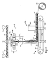
- Figures 1-6 show an illustrative apparatus for carrying out various embodiments of the disclosure as part of an exemplary apparatus for forming a patterned spunbond fibrous web.
- Figure 1 is a schematic overall side view of the apparatus.
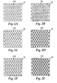
- Figures 2A-2F are top views of various exemplary perforated patterned collector surfaces useful in forming a patterned spunbond fibrous web according to certain illustrative embodiments of the present disclosure.
- Figures 3 and 4 are enlarged views of an optional filament attenuating portion of the apparatus of Figure 1 .
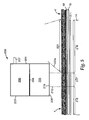
- Figures 5 and 6 are enlarged views of an optional filament bonding portion of the apparatus shown in Figure 1 .
- a spunbond nonwoven fibrous web 5 having a two- or three-dimensional patterned surface 4' may be formed by capturing melt spun filaments 15 on a patterned collector surface 19' and bonding the filaments without an adhesive while on the collector 19, for example, by thermally bonding the filaments on the collector 19 under a through-air bonder 200.
- the collector 19 is generally porous (e.g., perforated) and a gas-withdrawal device 14 can be positioned below the collector to assist deposition of filaments onto the collector.
- the spunbond web 5 having a pattern 4' maintained by the bonded filaments 15, may be wound up in a roll 23.
- a stream 15 of continuous melt spun filaments is prepared in filament-forming apparatus 2 and directed toward collection apparatus 3.
- the stream of continuous melt spun filaments 15 is collected in the form of a patterned fibrous melt spun web 5 having a patterned surface 4 on a patterned surface 19' of collector 19, which is illustrated as a continuous or endless belt collector.
- the patterned surface 4 of the patterned fibrous melt spun web 5 is shown opposite the a top surface distal from the patterned surface 19' of collector 19 in Figure 1 , it will be understood that in an alternative embodiment (not shown in the figures), the patterned surface of the patterned fibrous melt spun web may contact the patterned surface of the collector.
- Exemplary embodiments of the presently disclosed invention may be practiced by collecting the patterned fibrous web 5 on a continuous screen-type collector such as the belt-type collector 19 as shown in Figure 1 , on a perforated template or stencil (see Figure 2 ) bearing a surface pattern corresponding to the perforations and overlaying at least a portion of a porous or perforated collector (e.g. the screen-type collector of Figure 1 ), or on a screen-covered drum (not shown), or using alternative methods known in the art.
- a continuous screen-type collector such as the belt-type collector 19 as shown in Figure 1
- a perforated template or stencil see Figure 2
- a surface pattern corresponding to the perforations and overlaying at least a portion of a porous or perforated collector (e.g. the screen-type collector of Figure 1 ), or on a screen-covered drum (not shown), or using alternative methods known in the art.
- the filament-forming apparatus 2 in Figure 1 is one exemplary apparatus for use in practicing certain embodiments of the present disclosure.
- filament-forming material is brought to an extrusion head 10 in this illustrative apparatus, for example, by introducing a polymeric filament-forming material into a hopper 11, melting the material in an extruder 12, and pumping the molten material into the extrusion head 10 through a pump 13.
- solid polymeric material in pellet or other particulate form is most commonly used and melted to a liquid, pumpable state, other filament-forming liquids such as polymer solutions can also be used.
- the extrusion head 10 may be a conventional spinnerette or spin pack, generally including multiple orifices arranged in a regular pattern, e.g., straightline rows.
- Filaments 15 of filament-forming liquid are extruded from the extrusion head and conveyed to a processing chamber or optional attenuator 16.
- the distance 17 the extruded filaments 15 travel before reaching the optional attenuator 16 can vary, as can the conditions to which they are exposed.
- quenching streams 18 of air or other gas are presented to the extruded filaments to reduce the temperature of the extruded filaments 15.
- the streams of air or other gas may be heated to facilitate drawing of the filaments.
- there may be one or more streams of air or other fluid for example, a first air stream 18a blown transversely to the filament stream, which may remove undesired gaseous materials or fumes released during extrusion; and a second quenching air stream 18b that achieves a major desired temperature reduction.
- Additional quenching streams may be used; for example, the stream shown as 18b in Figure 1 could itself comprise more than one stream to achieve a desired level of quenching.
- the quenching air may be sufficient to solidify the extruded filaments 15 before they reach the optional attenuator 16.
- the extruded filaments are still in a softened or molten condition when they enter the optional attenuator.
- no quenching streams are used; in such a case ambient air or other fluid between the extrusion head 10 and the optional attenuator 16 may be a medium for any change in the extruded filaments before they enter the optional attenuator.
- the patterned collector surface 19' comprises a plurality of geometrically shaped perforations 100-105 extending through the collector 19, and capturing the population of filaments comprises drawing a vacuum through the perforated patterned collector surface.
- a perforated patterned surface is shown in Figure 1 , other implementations, for example, a perforated patterned stencil or template positioned on a porous or perforated screen or belt, may be used as well.
- the plurality of geometrically shaped perforations have a shape selected from the group consisting of circular ( Figure 2A ; 100), oval (not shown), polygonal ( Figures 2B-2C and 2E ; 101-102 and 104), V-shape ( Figure 2D ; 103), X-shape ( Figure 2F ; 105), and combinations thereof (not shown).
- the plurality of geometrically shaped perforations may have a polygonal shape selected from the group consisting of square ( Figure 2B ; 101), rectangular (not shown), triangular ( Figure 2C ; 102), diamond ( Figure 2E ; 104); trapezoidal (not shown), pentagonal (not shown), hexagonal (not shown), octagonal (not shown), and combinations thereof (not shown).
- the plurality of geometrically shaped perforations comprises a two-dimensional pattern on the patterned collector surface.
- the two-dimensional pattern of geometrically shaped perforations on the patterned collector surface is a two-dimensional array, as illustrated by Figures 2A-2F .
- the filaments 15 may pass through an optional attenuator 16, and eventually exit onto the collector 19 where they are collected as a patterned fibrous web 5, as discussed above.
- the distance 21 between the optional attenuator exit and the collector may be varied to obtain different effects.
- moving the attenuator relative to the collector, or changing the air flow rate through the attenuator may be advantageously used to increase or decrease the local basis weight of filaments in the patterned spunbond fibrous web.
- Operating the attenuator at a greater distance from the collector or at a lower air flow rate generally reduces the fraction of fibers collected in the perforations of the patterned collector surface, thereby reducing the local basis weight.
- the local basis weight of the patterned spunbond fibrous web may be varied in the machine direction (i.e. down-web) and/or in the traverse (i.e. cross-web) direction.
- FIG. 3 is an enlarged side view of a representative optional attenuator 16 for preparing spunbond filaments that are especially useful in webs of the present disclosure.
- the optional attenuator 16 comprises two movable halves or sides 16a and 16b separated so as to define between them the processing chamber 24: the facing surfaces of the sides 16a and 16b form the walls of the chamber.
- FIG 4 is a top and somewhat schematic view at a different scale showing the representative optional attenuator 16 and some of its mounting and support structure.
- the processing (attenuation) chamber 24 (as shown in Figure 3 ) is generally an elongated slot, having a transverse length 25 (transverse to the path of travel of filaments through the optional attenuator).
- the representative optional attenuator 16 includes slanted entry walls 27, which define an entrance space or throat 24a of the attenuation chamber 24.
- the entry walls 27 preferably are curved at the entry edge or surface 27a to smooth the entry of air streams carrying the extruded filaments 15 (not shown in Figures 3-4 ).
- the walls 27 are attached to a main body portion 28, and may be provided with a recessed area 29 to establish a gap 30 between the body portion 28 and wall 27.
- Air (represented by the arrows) may be introduced into the gaps 30 through conduits 31, creating air knives 32 that increase the velocity of the filaments traveling through the optional attenuator, and that also have a further quenching effect on the filaments.
- the optional attenuator body 28 is preferably curved at 28a to smooth the passage of air from the air knife 32 into the passage 24.
- the angle ( ⁇ ) of the surface 28b of the optional attenuator body can be selected to determine the desired angle at which the air knife impacts a stream of filaments passing through the optional attenuator.
- the air knives may be disposed further within the chamber.
- FIG. 3 illustrates one exemplary optional attenuation chamber that may be useful in practicing embodiments of the present disclosure; other configurations may be used.
- the optional attenuator 16 may comprise an attenuation chamber 24 that may have a uniform gap width (the horizontal distance 33 on the page of Figure 3 between the two optional attenuator sides is herein called the gap width) over its longitudinal length through the optional attenuator (the dimension along a longitudinal axis 26 through the attenuation chamber is called the axial length).
- the gap width may vary along the length of the optional attenuator chamber.
- the attenuation chamber is defined by straight or flat walls; in such embodiments the spacing between the walls may be constant over their length, or alternatively the walls may slightly diverge or converge (preferred because it tends to cause a widening of the microfilament stream) over the axial length of the attenuation chamber.
- the walls defining the attenuation chamber are regarded as parallel herein, because the deviation from exact parallelism is relatively slight.
- the walls defining the main portion of the longitudinal length of the passage 24 may take the form of plates 36 that are separate from, and attached to, the main body portion 28.
- the length of the attenuation chamber 24 can be varied to achieve different effects; variation is especially useful with the portion between the air knives 32 and the exit opening 34, sometimes called herein the chute length 35.
- the angle between the chamber walls and the axis 26 may be wider near the exit 34 to change the distribution of filaments onto the collector; or structure such as deflector surfaces, curved surfaces exhibiting the Coanda effect, and uneven wall lengths may be used at the exit to achieve a desired spreading or other distribution of filaments.
- the gap width, chute length, attenuation chamber shape, etc. are chosen in conjunction with the material being processed and the mode of treatment desired to achieve desired effects. For example, longer chute lengths may be useful to increase the crystallinity of prepared filaments. Conditions are chosen and can be widely varied to process the extruded filaments into a desired filament form.
- the two sides 16a and 16b of the representative optional attenuator 16 are each supported through mounting blocks 37 attached to linear bearings 38 that slide on rods 39.
- the bearing 38 has a low-friction travel on the rod through means such as axially extending rows of ball-bearings disposed radially around the rod, whereby the sides 16a and 16b can readily move toward and away from one another.
- air cylinders 43a and 43b are connected, respectively, to the optional attenuator sides 16a and 16b through connecting rods 44 and apply a clamping force pressing the optional attenuator sides 16a and 16b toward one another.
- Some useful modes of operation of the optional attenuator 16 are described in U.S. Patent No. 6,607,624 (Berrigan et al. ). For example, movement of the optional attenuator sides or chamber walls may occur when there is a perturbation of the system, such as when a filament being processed breaks or tangles with another filament or filament.
- the processing chamber does include side walls, though a single side wall at one transverse end of the chamber is not attached to both chamber sides 16a and 16b, because attachment to both chamber sides would prevent separation of the sides as discussed above. Instead, a sidewall(s) may be attached to one chamber side and move with that side when and if it moves in response to changes of pressure within the passage. In other embodiments, the side walls are divided, with one portion attached to one chamber side, and the other portion attached to the other chamber side, with the sidewall portions preferably overlapping if it is desired to confine the stream of processed filaments within the processing chamber.
- Various processes conventionally used as adjuncts to filament-forming processes may be used in connection with filaments as they enter or exit from the optional attenuator, such as spraying of finishes or other materials onto the filaments, application of an electrostatic charge to the filaments, application of water mists, etc.
- various materials may be added to a patterned collected web, including bonding agents, adhesives, finishes, and other webs or films.
- light autogenous bonding provided by through-air bonding may not provide the desired web strength for peel or shear performance
- a secondary or supplemental bonding step for example, point bonding calendering
- Other methods for achieving increased strength may include extrusion lamination or polycoating of a film layer onto the back (i.e., non-patterned) side of the patterned spunbond fibrous web, or bonding the patterned spunbond fibrous web to a support web (e.g., a conventional spunbond web, a nonporous film, a porous film, a printed film, or the like).
- Virtually any bonding technique may be used, for example, application of one or more adhesives to one or more surfaces to be bonded, ultrasonic welding, or other thermal bonding methods able to form localized bond patterns, as known to those skilled in the art. Such supplemental bonding may make the web more easily handled and better able to hold its shape.
- patterned spunbond nonwoven fibrous webs 5 having a two- or three-dimensional patterned surface 4 may be formed by capturing melt spun filaments on a patterned collector surface 19' and bonding the filaments without an adhesive while on the collector 19, for example, by thermally bonding the filaments without use of an adhesive while on the collector 19 under a through-air bonder 200.
- the presently preferred through-air bonding technique involves subjecting the collected patterned web of spunbond filaments to a controlled heating and quenching operation that includes a) forcefully passing through the web a gaseous stream heated to a temperature sufficient to soften the spunbond filaments sufficiently to cause the spunbond filaments to bond together at points of filament intersection (e.g., at sufficient points of intersection to form a coherent or bonded matrix), the heated stream being applied for a discrete time too short to wholly melt the filaments, and b) immediately forcefully passing through the web a gaseous stream at a temperature at least 50 °C less than the heated stream to quench the filaments (as defined in the above-mentioned U.S. Pat. Pub. No.
- a variation of the described method takes advantage of the presence of two different kinds of molecular phases within spunbond filaments - one kind called crystallite-characterized molecular phases because of a relatively large presence of chain-extended, or strain-induced, crystalline domains, and a second kind called amorphous-characterized phases because of a relatively large presence of domains of lower crystalline order (i.e., not chain-extended) and domains that are amorphous, though the latter may have some order or orientation of a degree insufficient for crystallinity.
- the first phase characterized by a larger presence of chain-extended crystalline domains melts at a temperature (e.g., the melting point of the chain-extended crystalline domain) that is higher than the temperature at which the second phase melts or softens (e.g., the glass transition temperature of the amorphous domain as modified by the melting points of the lower-order crystalline domains).
- a temperature e.g., the melting point of the chain-extended crystalline domain
- softens e.g., the glass transition temperature of the amorphous domain as modified by the melting points of the lower-order crystalline domains
- heating is at a temperature and for a time sufficient for the amorphous-characterized phase of the filaments to melt or soften while the crystallite-characterized phase remains unmelted.
- the heated gaseous stream is at a temperature greater than the onset melting temperature of the polymeric material of the filaments.
- the spunbond filaments Treatment of the collected web at such a temperature is found to cause the spunbond filaments to become morphologically refined, which is understood as follows (we do not wish to be bound by statements herein of our "understanding,” which generally involve some theoretical considerations).
- the amount of molecular material of the phase susceptible to undesirable (softening-impeding) crystal growth is not as great as it was before treatment.
- the amorphous-characterized phase is understood to have experienced a kind of cleansing or reduction of molecular structure that would lead to undesirable increases in crystallinity in conventional untreated filaments during a thermal bonding operation.
- Treated filaments of certain exemplary embodiments of the presently described invention may be capable of a kind of "repeatable softening,” meaning that the filaments, and particularly the amorphous-characterized phase of the filaments, will undergo to some degree a repeated cycle of softening and resolidifying as the filaments are exposed to a cycle of raised and lowered temperature within a temperature region lower than that which would cause melting of the whole filament.
- repeatable softening is indicated when a treated web (which already generally exhibits a useful bonding as a result of the heating and quenching treatment) can be heated to cause further autogenous bonding of the filaments.
- the cycling of softening and resolidifying may not continue indefinitely, but it is generally sufficient that the filaments may be initially bonded by exposure to heat, e.g., during a heat treatment according to certain exemplary embodiments of the presently described invention, and later heated again to cause re-softening and further bonding, or, if desired, other operations, such as calendering or re-shaping.
- a web may be calendered to a smooth surface or given a nonplanar shape, e.g., molded into a face mask, taking advantage of the improved bonding capability of the filaments (though in such cases the bonding is not limited to autogenous bonding).
- the crystallite-characterized phase of the filament also may have an important role, namely to reinforce the basic filament structure of the filaments.
- the crystallite-characterized phase generally can remain unmelted during a bonding or like operation because its melting point is higher than the melting/softening point of the amorphous-characterized phase, and it thus remains as an intact matrix that extends throughout the filament and supports the filament structure and filament dimensions.
- heating the web in an autogenous bonding operation may cause filaments to weld together by undergoing some flow and coalescence at points of filament intersection
- the basic discrete filament structure is substantially retained over the length of the filaments between intersections and bonds; preferably, the cross-section of the filaments remains unchanged over the length of the filaments between intersections or bonds formed during the operation.
- calendering of a web may cause filaments to be reconfigured by the pressure and heat of the calendering operation (thereby causing the filaments to permanently retain the shape pressed upon them during calendering and make the web more uniform in thickness)
- the filaments generally remain as discrete filaments with a consequent retention of desired web porosity, filtration, and insulating properties.
- a formed spunbond fibrous web 5 having a patterned surface 4 formed on the patterned collector surface 19' is carried by the moving collector 19 (see Figure 1 ) under a controlled-heating device 200 mounted above the collector 19 (see Figure 1 ).
- the exemplary heating device 200 comprises a housing 201 which is divided into an upper plenum 202 and a lower plenum 203. The upper and lower plenums are separated by a plate 204 perforated with a series of holes 205 that are typically uniform in size and spacing.
- a gas typically air
- the plate 204 functions as a flow-distribution means to cause air fed into the upper plenum to be rather uniformly distributed when passed through the plate into the lower plenum 203.
- Other useful flow-distribution means include fins, baffles, manifolds, air dams, screens or sintered plates, i.e., devices that even the distribution of air.
- the bottom wall 208 of the lower plenum 203 is formed with an elongated slot 209 through which an elongated or knife-like stream 210 of heated air from the lower plenum is blown onto the patterned surface 4 of the melt spun fibrous web 5 traveling on the collector 19 below the heating device 200 (the patterned spunbond fibrous web 5 and collector 19 are shown as a partial cut-away in Figure 6 ).
- the air-exhaust device 14 preferably extends sufficiently to lie under the slot 209 of the heating device 200 (as well as extending downweb a distance 218 beyond the heated stream 210 and through an area marked 220, as will be discussed below).
- Heated air in the plenum is thus under an internal pressure within the plenum 203, and at the slot 209 it is further under the exhaust vacuum of the air-exhaust device 14.
- a perforated plate 211 may be positioned under the collector 19 (see Figure 1 ) to impose a kind of back pressure or flow-restriction means that assures the stream 210 of heated air will spread to a desired extent over the width or heated area of the collected patterned spunbond fibrous web 5 and be inhibited in streaming through possible lower-density portions of the collected mass.
- Other useful flow-restriction means include screens or sintered plates.
- the number, size and density of openings in the plate 211 may be varied in different areas to achieve desired control. Large amounts of air pass through the microfilament-forming apparatus and must be disposed of as the filaments reach the collector in the region 215 (see Figure 1 ). Sufficient air passes through the web and collector in the region 216 to hold the web in place under the various streams of processing air. And sufficient openness is needed in the plate under the heat-treating region 217 to allow treating air to pass through the web, while sufficient resistance is provided to assure that the air is evenly distributed.
- the level of autogenous bonding between the filaments that form the patterned spunbond fibrous web may be controlled.
- the air flow and temperature are adjusted to allow the patterned spunbond fibrous web to be removed from the patterned collector surface without destroying the two-dimensional or three-dimensional surface pattern formed by contact with the patterned surface of the collector.
- the filaments may form a stable three-dimensional structure that may allow the patterned spunbond fibrous web to be more easily handled.
- the patterned spunbond fibrous web may exhibit higher extension (e.g. stretch), and may also be more readily thermally laminated to other layers without using temperatures exceeding the crystalline melting point of the material (e.g. a (co)polymer) making up the filaments.
- the material e.g. a (co)polymer
- the temperature and exposure time conditions of the patterned spunbond fibrous web are carefully controlled.
- the temperature-time conditions may be controlled over the whole heated area of the mass.
- the temperature of the stream 210 of heated air passing through the web is within a range of 5°C, and preferably within 2 or even 1°C, across the width of the mass being treated (the temperature of the heated air is often measured for convenient control of the operation at the entry point for the heated air into the housing 201, but it also can be measured adjacent the collected web with thermocouples).
- the heating apparatus is operated to maintain a steady temperature in the stream over time, e.g., by rapidly cycling the heater on and off to avoid over- or under-heating.
- the temperature is held within one degree Centigrade of the intended temperature when measured at one second intervals.
- the mass is subjected to quenching quickly after the application of the stream 210 of heated air.
- a quenching can generally be obtained by drawing ambient air over and through the patterned spunbond fibrous web 5 immediately after the mass leaves the controlled hot air stream 210.
- Numeral 220 in Figure 5 represents an area in which ambient air is drawn through the patterned web by the air-exhaust device after the web has passed through the hot air stream.
- air can be drawn under the base of the housing 201, e.g., in the area 220a marked on Figure 6 of the drawings, so that it reaches the web almost immediately after the web leaves the hot air stream 210.
- the air-exhaust device 14 extends along the collector for a distance 218 beyond the heating device 200 to assure thorough cooling and quenching of the whole patterned spunbond fibrous web 5.
- the combined heating and quenching apparatus is termed a quenched flow heater.
- One aim of the quenching is to withdraw heat before undesired changes occur in the spunbond filaments contained in the web.
- Another aim of the quenching is to rapidly remove heat from the web and the filaments and thereby limit the extent and nature of crystallization or molecular ordering that will subsequently occur in the filaments.
- rapid quenching from the molten/softened state to a solidified state the amorphous-characterized phase is understood to be frozen into a more purified crystalline form, with reduced molecular material that can interfere with softening, or repeatable softening, of the filaments.
- quenching may not be absolutely required though it is strongly preferred for most purposes.
- the mass is desirably cooled by a gas at a temperature at least 50°C less than the nominal melting point; also the quenching gas is desirably applied for a time on the order of at least one second (the nominal melting point is often stated by a polymer supplier; it can also be identified with differential scanning calorimetry, and for purposes herein, the "Nominal Melting Point" for a polymer is defined as the peak maximum of a second-heat, total-heat-flow DSC plot in the melting region of a polymer if there is only one maximum in that region; and, if there are more than one maximum indicating more than one melting point (e.g., because of the presence of two distinct crystalline phases), as the temperature at which the highest-amplitude melting peak occurs). In any event the quenching gas or other fluid has sufficient heat capacity to rapidly solidify the filaments.
- melt spun filaments may be collected on a patterned surface of a collector and one or more additional layer(s) of fibrous material capable of bonding to the filaments may be applied on, over or around the filaments, thereby bonding together the filaments before the filaments are removed from the collector surface.
- the additional layer(s) could be, for example, one or more meltblown layers, or one or more extrusion laminated film layer(s).
- the layer(s) would not need to be physically entangled, but would generally need some level of interlayer bonding along the interface between layer(s). In such embodiments, it may not be necessary to bond together the filaments using through-air bonding in order to retain the pattern on the surface of the patterned spunbond fibrous web.
- different filament-forming materials may be extruded through different orifices of a meltspinning extrusion head so as to prepare webs that comprise a mixture of filaments.
- Various procedures are also available for electrically charging a nonwoven fibrous web to enhance its filtration capacity: see, e.g., U.S. Pat. No. 5,496,507 (Angadjivand ).
- one or more of the following process steps may be carried out on the web once formed:
- the present disclosure is also directed to methods of using the patterned spunbond fibrous webs of the present disclosure in a variety of applications.
- the disclosure relates to articles comprising the composite nonwoven fibrous webs described above prepared according to the foregoing methods.
- Certain particular exemplary articles may be useful as a gas filtration article, a liquid filtration article, a sound absorption article, a thermal insulation article, a surface cleaning article, an abrasive article, a cellular growth support article, a drug delivery article, a personal hygiene article, and a wound dressing article.
- exemplary patterned spunbond fibrous webs of the present disclosure may be useful in providing a fluid distribution layer when used for gas or liquid filtration.
- Exemplary patterned spunbond fibrous webs of the present disclosure may provide additional surface area for thermal or acoustical dampening.
- Exemplary patterned spunbond fibrous webs of the present disclosure may provide a particularly effective textured surface for use in a wipe for surface cleaning, because the pattern may have the advantage of providing a reservoir for cleaning agents and high surface for trapping debris.
- Exemplary patterned spunbond fibrous webs of the present disclosure may be useful in providing a dust extraction layer in an abrasive article for use in a sanding operation.
- Exemplary patterned spunbond fibrous webs of the present disclosure may provide a scaffold for supporting cell growth, or an easily removable textured wound dressing material exhibiting less surface contact with the wound, and therefore being more readily removable and allowing the wound to breathe.
- the unique orientation of the filaments as determined by the pattern may lead to selective wicking of fluids.
- Exemplary patterned spunbond fibrous webs of the present disclosure may be particularly useful as a loop material for a hook-and-loop mechanical fastener or closure.
- a light bonding level obtained after through-air bonding may allow a hook to more easily penetrate the surface of a patterned spunbond fibrous web and engage with the loops formed by the filaments of the web.
- Patterned surface collectors in the form of flexible, adhesive backed rubber sandblasting stencils each stencil having a patterned surface in the form of a plurality of geometrically-shaped perforations as exemplified by Figures 2A-2F , were positioned on (and additionally taped to) the continuous belt screen 211 ( Figure 6 ) of the melt spinning apparatus exemplified by Figure 1 .
- the widths of the stencils were about 16 in (40.6 cm).
- the thicknesses of the sandblasting stencils, and depths of the perforations were about 1.3 mm.
- melt spun filaments were formed from Total 3868 polypropylene (Total Petrochemicals U.S.A., Inc.).
- the polymer melt temperature was 235°C.
- the filament quench zone temperature was 40°C with blower settings of 15 Hz in the upper zone and 8 Hz in the lower zone.
- the resulting filaments had a median diameter of 16 micrometers.
- the filaments were collected on the patterned surface collector to form a patterned melt spun fibrous web having a width of 15 in (38.1 cm).
- the attenuator was set with a 0.2 inch (0.51 cm) gap, and operated at an air blower setting of 60%.
- the attenuator was positioned 5 in (12.7 cm) above the collector surface.
- the through-air bonder was operated at 143°C and a blower setting of 60%, and was positioned 1.5 in (3.81 cm) above the surface of the patterned melt spun fibrous web. At this bonding temperature, the filaments formed sufficient bonds to permit removal of the patterned spunbond fibrous web from the collector surface as a self-supporting web after passing through the through-air bonder.
- Figure 7A shows an exemplary patterned spunbond fibrous web having an identifiable pattern in the form of an array of circles corresponding to the pattern on the collector surface, 0.25 in (0.64 cm) diameter circles with a pitch of 0.310 in (0.787 cm) and 60% perforated area.
- Figure 7B shows an exemplary patterned spunbond fibrous web having an identifiable pattern in the form of an array of squares corresponding to the pattern on the collector surface, 0.222 in (0.564 cm) squares (on side) having a pitch (offset) of 0.289 in (0.734 cm).
- Figure 7C shows an exemplary patterned spunbond fibrous web having an identifiable pattern in the form of an array of triangles corresponding to the pattern on the collector surface, equilateral triangles with a pitch of 0.438 in (1.113 cm).
- Figure 7D shows an exemplary patterned spunbond fibrous web having an identifiable pattern in the form of V-shaped "birds" as generally illustrated by Figure 2D .
- melt spun filaments were formed from Total 3868 polypropylene (Total Petrochemicals U.S.A., Inc.).
- the polymer melt temperature was 220°C, and the flow rate was 0.27 g/hole/min through a 648 hole die.
- the filament quench temperature was 40°C with blower settings of 26 Hz in the upper zone and 9 Hz in the lower zone.
- the filaments were collected on a patterned surface collector in the form of a 0.07 in (0.178 cm) thick metal plate having 0.375 in (0.953 cm) circular perforations arranged in a staggered array with a spacing between perforations of about 0.12 in (0.305 cm) to form a patterned melt spun fibrous web having a width of 21 in (53.34 cm).
- the perforated collector was positioned on the continuous belt screen 211 ( Figure 6 ) of the melt spinning apparatus exemplified by Figure 1 , and passed under the filament stream exiting the attenuator to collect the melt spun filaments as a patterned melt spun fibrous web on the patterned surface of the collector.
- the attenuator was set with a 0.02 inch (0.051 cm) gap, and operated at an air blower setting of 60% (yielding a restrictor pressure of 7 psig). The attenuator was positioned 7 in (16.8 cm) above the collector surface.
- the filaments on the collector were passed under a through-air bonder operating at 155°C.
- the through-air bonder had a slot length of 22 in (55.88 cm), a slot width of 2.75 in (6.99 cm), and was positioned 1.5 in (3.81 cm) above the surface of the patterned melt spun fibrous web. At this bonding temperature, the filaments formed sufficient bonds to permit removal of the patterned spunbond fibrous web from the collector surface as a self-supporting web after passing through the through-air bonder.
- Figure 7E shows the resulting patterned spunbond fibrous web having an identifiable pattern in the form of an array of circles corresponding to the pattern on the collector surface. Note in particular the high degree of filament orientation in a direction determined by the pattern.
Applications Claiming Priority (2)
| Application Number | Priority Date | Filing Date | Title |
|---|---|---|---|
| US14041208P | 2008-12-23 | 2008-12-23 | |
| PCT/US2009/067464 WO2010074982A1 (en) | 2008-12-23 | 2009-12-10 | Patterned spunbond fibrous webs and methods of making and using the same |
Publications (2)
| Publication Number | Publication Date |
|---|---|
| EP2376693A1 EP2376693A1 (en) | 2011-10-19 |
| EP2376693B1 true EP2376693B1 (en) | 2014-10-22 |
Family
ID=41694432
Family Applications (1)
| Application Number | Title | Priority Date | Filing Date |
|---|---|---|---|
| EP09795619.7A Revoked EP2376693B1 (en) | 2008-12-23 | 2009-12-10 | Patterned spunbond fibrous webs and methods of making and using the same |
Country Status (8)
| Country | Link |
|---|---|
| US (1) | US20110250378A1 (pt) |
| EP (1) | EP2376693B1 (pt) |
| JP (1) | JP5767113B2 (pt) |
| KR (1) | KR101597859B1 (pt) |
| CN (1) | CN102317526B (pt) |
| BR (1) | BRPI0923681A2 (pt) |
| IL (1) | IL213683A (pt) |
| WO (1) | WO2010074982A1 (pt) |
Cited By (2)
| Publication number | Priority date | Publication date | Assignee | Title |
|---|---|---|---|---|
| US10590577B2 (en) | 2016-08-02 | 2020-03-17 | Fitesa Germany Gmbh | System and process for preparing polylactic acid nonwoven fabrics |
| US11441251B2 (en) | 2016-08-16 | 2022-09-13 | Fitesa Germany Gmbh | Nonwoven fabrics comprising polylactic acid having improved strength and toughness |
Families Citing this family (46)
| Publication number | Priority date | Publication date | Assignee | Title |
|---|---|---|---|---|
| US8906275B2 (en) * | 2012-05-29 | 2014-12-09 | Nike, Inc. | Textured elements incorporating non-woven textile materials and methods for manufacturing the textured elements |
| US9682512B2 (en) | 2009-02-06 | 2017-06-20 | Nike, Inc. | Methods of joining textiles and other elements incorporating a thermoplastic polymer material |
| US20100199406A1 (en) | 2009-02-06 | 2010-08-12 | Nike, Inc. | Thermoplastic Non-Woven Textile Elements |
| US8911796B2 (en) | 2009-06-02 | 2014-12-16 | Akzo Nobel Chemicals International B.V. | Non-caking salt composition, preparation process and use thereof |
| CN103025941B (zh) * | 2010-07-07 | 2016-08-10 | 3M创新有限公司 | 图案化的气纺非织造纤维网及其制备和使用方法 |
| BR112013000010A2 (pt) * | 2010-07-07 | 2016-05-10 | 3M Innovative Properties Co | mantas fibrosas de eletreto não tecido e método para fabricação de uma manta fibrosa de eletreto não tecida |
| CN102260963A (zh) * | 2011-06-28 | 2011-11-30 | 西南交通大学 | 一种制备微纳米级图案化电纺纤维膜的方法 |
| CN102560895B (zh) * | 2011-11-22 | 2014-04-02 | 广州市三泰汽车内饰材料有限公司 | 一种无纺纤维织物生产设备 |
| US9913764B2 (en) * | 2013-12-18 | 2018-03-13 | Kimberly-Clark Worldwide, Inc. | Post-bonded grooved elastic materials |
| JP6793117B2 (ja) * | 2014-10-01 | 2020-12-02 | スリーエム イノベイティブ プロパティズ カンパニー | デブリードマンのための多孔質デバイス、キット、及び方法 |
| KR101732253B1 (ko) | 2015-05-12 | 2017-05-08 | 주식회사 불스원 | 유막 제거용 섬유 와이퍼 |
| WO2016196712A1 (en) | 2015-06-03 | 2016-12-08 | The Procter & Gamble Company | Article of manufacture making system |
| WO2016196711A1 (en) | 2015-06-03 | 2016-12-08 | The Procter & Gamble Company | Article of manufacture making system |
| US10543488B2 (en) | 2015-06-12 | 2020-01-28 | The Procter & Gamble Company | Discretizer and method of using same |
| EP3325714A1 (en) | 2015-07-24 | 2018-05-30 | The Procter and Gamble Company | Textured fibrous structures |
| RU2673772C1 (ru) | 2015-07-31 | 2018-11-29 | Дзе Проктер Энд Гэмбл Компани | Формирующий ленточный конвейер для формованного нетканого материала |
| BR112018002059B1 (pt) | 2015-07-31 | 2023-02-14 | The Procter & Gamble Company | Embalagem de artigos para cuidados pessoais |
| US10858768B2 (en) | 2015-07-31 | 2020-12-08 | The Procter & Gamble Company | Shaped nonwoven |
| DE102015217569B4 (de) * | 2015-09-15 | 2019-05-29 | Voith Patent Gmbh | Verfahren zur Herstellung von Spinnvliesbahnen |
| CN105251047B (zh) * | 2015-09-30 | 2018-04-27 | 温州生物材料与工程研究所 | 电纺多孔纳米纤维基质微图案印章支架材料及其制备方法和用途 |
| CA3006969C (en) * | 2015-12-17 | 2021-06-15 | The Procter & Gamble Company | Shaped nonwoven |
| PL3239378T3 (pl) | 2016-04-29 | 2019-07-31 | Reifenhäuser GmbH & Co. KG Maschinenfabrik | Urządzenie i sposób do wytwarzania włóknin z włókien ciągłych |
| US10801141B2 (en) | 2016-05-24 | 2020-10-13 | The Procter & Gamble Company | Fibrous nonwoven coform web structure with visible shaped particles, and method for manufacture |
| DE102016223571B4 (de) | 2016-11-28 | 2020-08-13 | Adidas Ag | Herstellung von Vliesstoffen einschließlich einer Komponente |
| US10888471B2 (en) | 2016-12-15 | 2021-01-12 | The Procter & Gamble Company | Shaped nonwoven |
| US10973699B2 (en) | 2016-12-20 | 2021-04-13 | The Procter & Gamble Company | Methods and apparatuses for making elastomeric laminates with elastic strands unwound from beams |
| JP6946441B2 (ja) | 2017-01-31 | 2021-10-06 | ザ プロクター アンド ギャンブル カンパニーThe Procter & Gamble Company | 成形不織布及び成形不織布を含む物品 |
| JP7440264B2 (ja) | 2017-01-31 | 2024-02-28 | ザ プロクター アンド ギャンブル カンパニー | 成形不織布 |
| EP3576700B1 (en) | 2017-01-31 | 2022-11-30 | The Procter & Gamble Company | Shaped nonwoven |
| WO2019005910A1 (en) | 2017-06-30 | 2019-01-03 | The Procter & Gamble Company | METHOD FOR MANUFACTURING NON-WOVEN FABRIC |
| CN110799161B (zh) | 2017-06-30 | 2022-08-26 | 宝洁公司 | 成型非织造布 |
| US11129753B2 (en) | 2017-09-01 | 2021-09-28 | The Procter & Gamble Company | Methods and apparatuses for making elastomeric laminates |
| US11925537B2 (en) | 2017-09-01 | 2024-03-12 | The Procter & Gamble Company | Beamed elastomeric laminate structure, fit, and texture |
| US11147718B2 (en) | 2017-09-01 | 2021-10-19 | The Procter & Gamble Company | Beamed elastomeric laminate structure, fit, and texture |
| CN111201004B (zh) | 2017-10-13 | 2022-10-28 | 宝洁公司 | 包含具有改善的热导率的非织造材料的吸收制品 |
| US11547613B2 (en) | 2017-12-05 | 2023-01-10 | The Procter & Gamble Company | Stretch laminate with beamed elastics and formed nonwoven layer |
| US10765565B2 (en) | 2018-01-25 | 2020-09-08 | The Procter & Gamble Company | Method for manufacturing topsheets for absorbent articles |
| CN112236114A (zh) | 2018-06-12 | 2021-01-15 | 宝洁公司 | 非织造织物以及具有成型的、柔软的和纹理化的非织造织物的吸收制品 |
| CA3108036A1 (en) | 2018-08-03 | 2020-02-06 | 3M Innovative Properties Company | Air-filter media comprising a relofted spunbonded web, and methods of making and using |
| US11850128B2 (en) | 2018-09-27 | 2023-12-26 | The Procter And Gamble Company | Garment-like absorbent articles |
| WO2020107422A1 (en) | 2018-11-30 | 2020-06-04 | The Procter & Gamble Company | Methods of creating soft and lofty nonwoven webs |
| CN113166994B (zh) | 2018-11-30 | 2022-09-30 | 宝洁公司 | 用于制备通流粘结的非织造纤维网的方法 |
| GB2596718A (en) | 2019-03-18 | 2022-01-05 | Procter & Gamble | Shaped nonwovens that exhibit high visual resolution |
| US11819393B2 (en) | 2019-06-19 | 2023-11-21 | The Procter & Gamble Company | Absorbent article with function-formed topsheet, and method for manufacturing |
| CN114981490A (zh) * | 2020-01-10 | 2022-08-30 | 金伯利-克拉克环球有限公司 | 制造均匀纺粘长丝非织造幅材的方法 |
| CN112680882B (zh) * | 2020-12-11 | 2022-07-05 | 厦门保瑞达环保科技有限公司 | 一种高精度直立型过滤毡制作方法 |
Family Cites Families (23)
| Publication number | Priority date | Publication date | Assignee | Title |
|---|---|---|---|---|
| US4103058A (en) | 1974-09-20 | 1978-07-25 | Minnesota Mining And Manufacturing Company | Pillowed web of blown microfibers |
| DE2530499C3 (de) * | 1975-07-09 | 1978-05-24 | Akzo Gmbh, 5600 Wuppertal | Mattenbahn und Verfahren zu ihrer Herstellung |
| US4729371A (en) | 1983-10-11 | 1988-03-08 | Minnesota Mining And Manufacturing Company | Respirator comprised of blown bicomponent fibers |
| US4741941A (en) * | 1985-11-04 | 1988-05-03 | Kimberly-Clark Corporation | Nonwoven web with projections |
| CA2105026C (en) | 1993-04-29 | 2003-12-16 | Henry Louis Griesbach Iii | Shaped nonwoven fabric and method for making the same |
| EP0714463B1 (en) | 1993-08-17 | 1999-03-10 | Minnesota Mining And Manufacturing Company | Method of charging electret filter media |
| US6093665A (en) | 1993-09-30 | 2000-07-25 | Kimberly-Clark Worldwide, Inc. | Pattern bonded nonwoven fabrics |
| JP3509178B2 (ja) * | 1994-03-23 | 2004-03-22 | 東洋紡績株式会社 | 塗膜防水補強材の製造方法 |
| US5545464A (en) * | 1995-03-22 | 1996-08-13 | Kimberly-Clark Corporation | Conjugate fiber nonwoven fabric |
| US5614281A (en) * | 1995-11-29 | 1997-03-25 | Kimberly-Clark Corporation | Creped nonwoven laminate loop fastening material for mechanical fastening systems |
| US5858515A (en) | 1995-12-29 | 1999-01-12 | Kimberly-Clark Worldwide, Inc. | Pattern-unbonded nonwoven web and process for making the same |
| US5810954A (en) * | 1996-02-20 | 1998-09-22 | Kimberly-Clark Worldwide, Inc. | Method of forming a fine fiber barrier fabric with improved drape and strength of making same |
| EP1157152A1 (en) * | 1998-11-17 | 2001-11-28 | Eldim, Inc. | Method and apparatus for manufacturing non-woven articles |
| JP4206570B2 (ja) * | 1999-04-23 | 2009-01-14 | チッソ株式会社 | 不織布およびそれを用いた吸収性物品 |
| IT1319160B1 (it) * | 2000-05-29 | 2003-09-26 | Italdreni S R L Ora Italdreni | Materassino in materiale termoplastico a bassa densita' ed alto indicedi vuoti, dispositivo e procedimento per la sua produzione. |
| US6607624B2 (en) | 2000-11-20 | 2003-08-19 | 3M Innovative Properties Company | Fiber-forming process |
| JP2002339221A (ja) * | 2001-03-13 | 2002-11-27 | Toyoda Spinning & Weaving Co Ltd | 立体不織布及びその製造方法 |
| US6921570B2 (en) * | 2001-12-21 | 2005-07-26 | Kimberly-Clark Worldwide, Inc. | Pattern unbonded nonwoven web and process for making same |
| EP1323857A3 (en) * | 2001-12-25 | 2005-02-02 | Toyoda Boshoku Corporation | Three-dimensional non-woven fabric, mold and method used therefore |
| US6916752B2 (en) | 2002-05-20 | 2005-07-12 | 3M Innovative Properties Company | Bondable, oriented, nonwoven fibrous webs and methods for making them |
| US9139940B2 (en) | 2006-07-31 | 2015-09-22 | 3M Innovative Properties Company | Bonded nonwoven fibrous webs comprising softenable oriented semicrystalline polymeric fibers and apparatus and methods for preparing such webs |
| US7807591B2 (en) | 2006-07-31 | 2010-10-05 | 3M Innovative Properties Company | Fibrous web comprising microfibers dispersed among bonded meltspun fibers |
| MX2009004110A (es) * | 2006-10-17 | 2009-05-05 | Fiberweb Simpsonville Inc | Tela no tejida con aberturas y procedimiento y aparato para producirla. |
-
2009
- 2009-12-10 JP JP2011543554A patent/JP5767113B2/ja not_active Expired - Fee Related
- 2009-12-10 WO PCT/US2009/067464 patent/WO2010074982A1/en active Application Filing
- 2009-12-10 EP EP09795619.7A patent/EP2376693B1/en not_active Revoked
- 2009-12-10 BR BRPI0923681A patent/BRPI0923681A2/pt not_active IP Right Cessation
- 2009-12-10 CN CN200980156830.0A patent/CN102317526B/zh not_active Expired - Fee Related
- 2009-12-10 KR KR1020117017169A patent/KR101597859B1/ko not_active IP Right Cessation
- 2009-12-10 US US13/140,448 patent/US20110250378A1/en not_active Abandoned
-
2011
- 2011-06-21 IL IL213683A patent/IL213683A/en not_active IP Right Cessation
Cited By (2)
| Publication number | Priority date | Publication date | Assignee | Title |
|---|---|---|---|---|
| US10590577B2 (en) | 2016-08-02 | 2020-03-17 | Fitesa Germany Gmbh | System and process for preparing polylactic acid nonwoven fabrics |
| US11441251B2 (en) | 2016-08-16 | 2022-09-13 | Fitesa Germany Gmbh | Nonwoven fabrics comprising polylactic acid having improved strength and toughness |
Also Published As
| Publication number | Publication date |
|---|---|
| CN102317526A (zh) | 2012-01-11 |
| IL213683A (en) | 2016-03-31 |
| CN102317526B (zh) | 2016-08-24 |
| KR20110117103A (ko) | 2011-10-26 |
| JP5767113B2 (ja) | 2015-08-19 |
| BRPI0923681A2 (pt) | 2016-01-19 |
| US20110250378A1 (en) | 2011-10-13 |
| EP2376693A1 (en) | 2011-10-19 |
| WO2010074982A1 (en) | 2010-07-01 |
| IL213683A0 (en) | 2011-07-31 |
| KR101597859B1 (ko) | 2016-02-25 |
| JP2012513547A (ja) | 2012-06-14 |
Similar Documents
| Publication | Publication Date | Title |
|---|---|---|
| EP2376693B1 (en) | Patterned spunbond fibrous webs and methods of making and using the same | |
| EP2231912B1 (en) | Composite nonwoven fibrous webs and methods of making and using the same | |
| US9382643B2 (en) | Apparatus, system, and method for forming nanofibers and nanofiber webs | |
| US9771675B2 (en) | Patterned air-laid nonwoven fibrous webs and methods of making and using same | |
| US20160206984A1 (en) | Melt-spinning process, melt-spun nonwoven fibrous webs and related filtration media | |
| US20130108831A1 (en) | Patterned air-laid nonwoven electret fibrous webs and methods of making and using same | |
| US20110256791A1 (en) | Elastic nonwoven fibrous webs and methods of making and using | |
| JPH11505892A (ja) | 非延伸、強靭、耐久的溶融接着可能なマクロデニール熱可塑性プラスチック多成分フィラメント | |
| CA2269883A1 (en) | Undrawn, tough, durably melt-bondable, macrodenier, thermoplastic, multicomponent filaments | |
| JP4092297B2 (ja) | 内燃機関エンジンのエアフィルタに用いるためのメルトブローンフィルタ媒体の製造方法 | |
| CA2827950A1 (en) | Highly uniform spunbonded nonwoven fabrics | |
| JP2007500629A (ja) | 三次元フィルムおよびその製造法 |
Legal Events
| Date | Code | Title | Description |
|---|---|---|---|
| PUAI | Public reference made under article 153(3) epc to a published international application that has entered the european phase |
Free format text: ORIGINAL CODE: 0009012 |
|
| 17P | Request for examination filed |
Effective date: 20110711 |
|
| AK | Designated contracting states |
Kind code of ref document: A1 Designated state(s): AT BE BG CH CY CZ DE DK EE ES FI FR GB GR HR HU IE IS IT LI LT LU LV MC MK MT NL NO PL PT RO SE SI SK SM TR |
|
| DAX | Request for extension of the european patent (deleted) | ||
| 17Q | First examination report despatched |
Effective date: 20120328 |
|
| GRAP | Despatch of communication of intention to grant a patent |
Free format text: ORIGINAL CODE: EPIDOSNIGR1 |
|
| INTG | Intention to grant announced |
Effective date: 20140711 |
|
| GRAS | Grant fee paid |
Free format text: ORIGINAL CODE: EPIDOSNIGR3 |
|
| GRAA | (expected) grant |
Free format text: ORIGINAL CODE: 0009210 |
|
| AK | Designated contracting states |
Kind code of ref document: B1 Designated state(s): AT BE BG CH CY CZ DE DK EE ES FI FR GB GR HR HU IE IS IT LI LT LU LV MC MK MT NL NO PL PT RO SE SI SK SM TR |
|
| REG | Reference to a national code |
Ref country code: GB Ref legal event code: FG4D |
|
| REG | Reference to a national code |
Ref country code: CH Ref legal event code: EP |
|
| REG | Reference to a national code |
Ref country code: AT Ref legal event code: REF Ref document number: 692726 Country of ref document: AT Kind code of ref document: T Effective date: 20141115 |
|
| REG | Reference to a national code |
Ref country code: IE Ref legal event code: FG4D |
|
| REG | Reference to a national code |
Ref country code: DE Ref legal event code: R096 Ref document number: 602009027357 Country of ref document: DE Effective date: 20141204 |
|
| REG | Reference to a national code |
Ref country code: NL Ref legal event code: VDEP Effective date: 20141022 |
|
| REG | Reference to a national code |
Ref country code: AT Ref legal event code: MK05 Ref document number: 692726 Country of ref document: AT Kind code of ref document: T Effective date: 20141022 |
|
| REG | Reference to a national code |
Ref country code: LT Ref legal event code: MG4D |
|
| PG25 | Lapsed in a contracting state [announced via postgrant information from national office to epo] |
Ref country code: NO Free format text: LAPSE BECAUSE OF FAILURE TO SUBMIT A TRANSLATION OF THE DESCRIPTION OR TO PAY THE FEE WITHIN THE PRESCRIBED TIME-LIMIT Effective date: 20150122 Ref country code: LT Free format text: LAPSE BECAUSE OF FAILURE TO SUBMIT A TRANSLATION OF THE DESCRIPTION OR TO PAY THE FEE WITHIN THE PRESCRIBED TIME-LIMIT Effective date: 20141022 Ref country code: PT Free format text: LAPSE BECAUSE OF FAILURE TO SUBMIT A TRANSLATION OF THE DESCRIPTION OR TO PAY THE FEE WITHIN THE PRESCRIBED TIME-LIMIT Effective date: 20150223 Ref country code: ES Free format text: LAPSE BECAUSE OF FAILURE TO SUBMIT A TRANSLATION OF THE DESCRIPTION OR TO PAY THE FEE WITHIN THE PRESCRIBED TIME-LIMIT Effective date: 20141022 Ref country code: IS Free format text: LAPSE BECAUSE OF FAILURE TO SUBMIT A TRANSLATION OF THE DESCRIPTION OR TO PAY THE FEE WITHIN THE PRESCRIBED TIME-LIMIT Effective date: 20150222 Ref country code: FI Free format text: LAPSE BECAUSE OF FAILURE TO SUBMIT A TRANSLATION OF THE DESCRIPTION OR TO PAY THE FEE WITHIN THE PRESCRIBED TIME-LIMIT Effective date: 20141022 Ref country code: NL Free format text: LAPSE BECAUSE OF FAILURE TO SUBMIT A TRANSLATION OF THE DESCRIPTION OR TO PAY THE FEE WITHIN THE PRESCRIBED TIME-LIMIT Effective date: 20141022 |
|
| PG25 | Lapsed in a contracting state [announced via postgrant information from national office to epo] |
Ref country code: PL Free format text: LAPSE BECAUSE OF FAILURE TO SUBMIT A TRANSLATION OF THE DESCRIPTION OR TO PAY THE FEE WITHIN THE PRESCRIBED TIME-LIMIT Effective date: 20141022 Ref country code: LV Free format text: LAPSE BECAUSE OF FAILURE TO SUBMIT A TRANSLATION OF THE DESCRIPTION OR TO PAY THE FEE WITHIN THE PRESCRIBED TIME-LIMIT Effective date: 20141022 Ref country code: GR Free format text: LAPSE BECAUSE OF FAILURE TO SUBMIT A TRANSLATION OF THE DESCRIPTION OR TO PAY THE FEE WITHIN THE PRESCRIBED TIME-LIMIT Effective date: 20150123 Ref country code: AT Free format text: LAPSE BECAUSE OF FAILURE TO SUBMIT A TRANSLATION OF THE DESCRIPTION OR TO PAY THE FEE WITHIN THE PRESCRIBED TIME-LIMIT Effective date: 20141022 Ref country code: HR Free format text: LAPSE BECAUSE OF FAILURE TO SUBMIT A TRANSLATION OF THE DESCRIPTION OR TO PAY THE FEE WITHIN THE PRESCRIBED TIME-LIMIT Effective date: 20141022 Ref country code: CY Free format text: LAPSE BECAUSE OF FAILURE TO SUBMIT A TRANSLATION OF THE DESCRIPTION OR TO PAY THE FEE WITHIN THE PRESCRIBED TIME-LIMIT Effective date: 20141022 Ref country code: SE Free format text: LAPSE BECAUSE OF FAILURE TO SUBMIT A TRANSLATION OF THE DESCRIPTION OR TO PAY THE FEE WITHIN THE PRESCRIBED TIME-LIMIT Effective date: 20141022 |
|
| PG25 | Lapsed in a contracting state [announced via postgrant information from national office to epo] |
Ref country code: BE Free format text: LAPSE BECAUSE OF NON-PAYMENT OF DUE FEES Effective date: 20141231 |
|
| REG | Reference to a national code |
Ref country code: DE Ref legal event code: R026 Ref document number: 602009027357 Country of ref document: DE |
|
| PLBI | Opposition filed |
Free format text: ORIGINAL CODE: 0009260 |
|
| PG25 | Lapsed in a contracting state [announced via postgrant information from national office to epo] |
Ref country code: CZ Free format text: LAPSE BECAUSE OF FAILURE TO SUBMIT A TRANSLATION OF THE DESCRIPTION OR TO PAY THE FEE WITHIN THE PRESCRIBED TIME-LIMIT Effective date: 20141022 Ref country code: EE Free format text: LAPSE BECAUSE OF FAILURE TO SUBMIT A TRANSLATION OF THE DESCRIPTION OR TO PAY THE FEE WITHIN THE PRESCRIBED TIME-LIMIT Effective date: 20141022 Ref country code: DK Free format text: LAPSE BECAUSE OF FAILURE TO SUBMIT A TRANSLATION OF THE DESCRIPTION OR TO PAY THE FEE WITHIN THE PRESCRIBED TIME-LIMIT Effective date: 20141022 Ref country code: LU Free format text: LAPSE BECAUSE OF FAILURE TO SUBMIT A TRANSLATION OF THE DESCRIPTION OR TO PAY THE FEE WITHIN THE PRESCRIBED TIME-LIMIT Effective date: 20141210 Ref country code: RO Free format text: LAPSE BECAUSE OF FAILURE TO SUBMIT A TRANSLATION OF THE DESCRIPTION OR TO PAY THE FEE WITHIN THE PRESCRIBED TIME-LIMIT Effective date: 20141022 Ref country code: SK Free format text: LAPSE BECAUSE OF FAILURE TO SUBMIT A TRANSLATION OF THE DESCRIPTION OR TO PAY THE FEE WITHIN THE PRESCRIBED TIME-LIMIT Effective date: 20141022 |
|
| REG | Reference to a national code |
Ref country code: CH Ref legal event code: PL |
|
| PLAX | Notice of opposition and request to file observation + time limit sent |
Free format text: ORIGINAL CODE: EPIDOSNOBS2 |
|
| 26 | Opposition filed |
Opponent name: THE PROCTER & GAMBLE COMPANY Effective date: 20150722 |
|
| PG25 | Lapsed in a contracting state [announced via postgrant information from national office to epo] |
Ref country code: IT Free format text: LAPSE BECAUSE OF FAILURE TO SUBMIT A TRANSLATION OF THE DESCRIPTION OR TO PAY THE FEE WITHIN THE PRESCRIBED TIME-LIMIT Effective date: 20141022 |
|
| GBPC | Gb: european patent ceased through non-payment of renewal fee |
Effective date: 20150122 |
|
| REG | Reference to a national code |
Ref country code: IE Ref legal event code: MM4A |
|
| REG | Reference to a national code |
Ref country code: FR Ref legal event code: ST Effective date: 20150831 |
|
| PG25 | Lapsed in a contracting state [announced via postgrant information from national office to epo] |
Ref country code: GB Free format text: LAPSE BECAUSE OF NON-PAYMENT OF DUE FEES Effective date: 20150122 Ref country code: CH Free format text: LAPSE BECAUSE OF NON-PAYMENT OF DUE FEES Effective date: 20141231 Ref country code: IE Free format text: LAPSE BECAUSE OF NON-PAYMENT OF DUE FEES Effective date: 20141210 Ref country code: LI Free format text: LAPSE BECAUSE OF NON-PAYMENT OF DUE FEES Effective date: 20141231 |
|
| PG25 | Lapsed in a contracting state [announced via postgrant information from national office to epo] |
Ref country code: FR Free format text: LAPSE BECAUSE OF NON-PAYMENT OF DUE FEES Effective date: 20141231 |
|
| PLAF | Information modified related to communication of a notice of opposition and request to file observations + time limit |
Free format text: ORIGINAL CODE: EPIDOSCOBS2 |
|
| PG25 | Lapsed in a contracting state [announced via postgrant information from national office to epo] |
Ref country code: SI Free format text: LAPSE BECAUSE OF FAILURE TO SUBMIT A TRANSLATION OF THE DESCRIPTION OR TO PAY THE FEE WITHIN THE PRESCRIBED TIME-LIMIT Effective date: 20141022 |
|
| PLBB | Reply of patent proprietor to notice(s) of opposition received |
Free format text: ORIGINAL CODE: EPIDOSNOBS3 |
|
| PG25 | Lapsed in a contracting state [announced via postgrant information from national office to epo] |
Ref country code: SM Free format text: LAPSE BECAUSE OF FAILURE TO SUBMIT A TRANSLATION OF THE DESCRIPTION OR TO PAY THE FEE WITHIN THE PRESCRIBED TIME-LIMIT Effective date: 20141022 |
|
| PG25 | Lapsed in a contracting state [announced via postgrant information from national office to epo] |
Ref country code: MC Free format text: LAPSE BECAUSE OF FAILURE TO SUBMIT A TRANSLATION OF THE DESCRIPTION OR TO PAY THE FEE WITHIN THE PRESCRIBED TIME-LIMIT Effective date: 20141022 |
|
| PG25 | Lapsed in a contracting state [announced via postgrant information from national office to epo] |
Ref country code: BG Free format text: LAPSE BECAUSE OF FAILURE TO SUBMIT A TRANSLATION OF THE DESCRIPTION OR TO PAY THE FEE WITHIN THE PRESCRIBED TIME-LIMIT Effective date: 20141022 |
|
| PG25 | Lapsed in a contracting state [announced via postgrant information from national office to epo] |
Ref country code: HU Free format text: LAPSE BECAUSE OF FAILURE TO SUBMIT A TRANSLATION OF THE DESCRIPTION OR TO PAY THE FEE WITHIN THE PRESCRIBED TIME-LIMIT; INVALID AB INITIO Effective date: 20091210 Ref country code: MT Free format text: LAPSE BECAUSE OF FAILURE TO SUBMIT A TRANSLATION OF THE DESCRIPTION OR TO PAY THE FEE WITHIN THE PRESCRIBED TIME-LIMIT Effective date: 20141022 Ref country code: TR Free format text: LAPSE BECAUSE OF FAILURE TO SUBMIT A TRANSLATION OF THE DESCRIPTION OR TO PAY THE FEE WITHIN THE PRESCRIBED TIME-LIMIT Effective date: 20141022 |
|
| PGFP | Annual fee paid to national office [announced via postgrant information from national office to epo] |
Ref country code: DE Payment date: 20161206 Year of fee payment: 8 |
|
| REG | Reference to a national code |
Ref country code: DE Ref legal event code: R064 Ref document number: 602009027357 Country of ref document: DE Ref country code: DE Ref legal event code: R103 Ref document number: 602009027357 Country of ref document: DE |
|
| RDAF | Communication despatched that patent is revoked |
Free format text: ORIGINAL CODE: EPIDOSNREV1 |
|
| STAA | Information on the status of an ep patent application or granted ep patent |
Free format text: STATUS: THE PATENT HAS BEEN GRANTED |
|
| RDAG | Patent revoked |
Free format text: ORIGINAL CODE: 0009271 |
|
| STAA | Information on the status of an ep patent application or granted ep patent |
Free format text: STATUS: PATENT REVOKED |
|
| 27W | Patent revoked |
Effective date: 20170519 |
|
| STAA | Information on the status of an ep patent application or granted ep patent |
Free format text: STATUS: PATENT REVOKED |