EP2376261B1 - Razor cartridge and mechanical razor comprising such a cartridge - Google Patents
Razor cartridge and mechanical razor comprising such a cartridge Download PDFInfo
- Publication number
- EP2376261B1 EP2376261B1 EP08875489.0A EP08875489A EP2376261B1 EP 2376261 B1 EP2376261 B1 EP 2376261B1 EP 08875489 A EP08875489 A EP 08875489A EP 2376261 B1 EP2376261 B1 EP 2376261B1
- Authority
- EP
- European Patent Office
- Prior art keywords
- blade
- support
- along
- strip
- station
- Prior art date
- Legal status (The legal status is an assumption and is not a legal conclusion. Google has not performed a legal analysis and makes no representation as to the accuracy of the status listed.)
- Active
Links
- 238000005520 cutting process Methods 0.000 claims description 24
- 238000005452 bending Methods 0.000 description 26
- 238000006073 displacement reaction Methods 0.000 description 15
- 239000000463 material Substances 0.000 description 13
- 238000000926 separation method Methods 0.000 description 10
- 238000004519 manufacturing process Methods 0.000 description 6
- 230000000295 complement effect Effects 0.000 description 3
- 238000000034 method Methods 0.000 description 3
- 230000001050 lubricating effect Effects 0.000 description 2
- 239000002184 metal Substances 0.000 description 2
- 238000012544 monitoring process Methods 0.000 description 2
- 239000004033 plastic Substances 0.000 description 2
- 238000003825 pressing Methods 0.000 description 2
- 230000033764 rhythmic process Effects 0.000 description 2
- 230000001360 synchronised effect Effects 0.000 description 2
- 239000004793 Polystyrene Substances 0.000 description 1
- 238000000137 annealing Methods 0.000 description 1
- 230000000712 assembly Effects 0.000 description 1
- 238000000429 assembly Methods 0.000 description 1
- 238000005097 cold rolling Methods 0.000 description 1
- 239000006185 dispersion Substances 0.000 description 1
- 238000002347 injection Methods 0.000 description 1
- 239000007924 injection Substances 0.000 description 1
- 238000003780 insertion Methods 0.000 description 1
- 230000037431 insertion Effects 0.000 description 1
- 238000007689 inspection Methods 0.000 description 1
- 238000009434 installation Methods 0.000 description 1
- 238000005304 joining Methods 0.000 description 1
- 230000014759 maintenance of location Effects 0.000 description 1
- 239000000203 mixture Substances 0.000 description 1
- 230000007935 neutral effect Effects 0.000 description 1
- 230000003287 optical effect Effects 0.000 description 1
- 229920002223 polystyrene Polymers 0.000 description 1
- 230000000284 resting effect Effects 0.000 description 1
- 229910001220 stainless steel Inorganic materials 0.000 description 1
- 239000010935 stainless steel Substances 0.000 description 1
- 229920002994 synthetic fiber Polymers 0.000 description 1
- 239000012815 thermoplastic material Substances 0.000 description 1
- 238000003466 welding Methods 0.000 description 1
- 238000004804 winding Methods 0.000 description 1
Images


Classifications
-
- B—PERFORMING OPERATIONS; TRANSPORTING
- B26—HAND CUTTING TOOLS; CUTTING; SEVERING
- B26B—HAND-HELD CUTTING TOOLS NOT OTHERWISE PROVIDED FOR
- B26B21/00—Razors of the open or knife type; Safety razors or other shaving implements of the planing type; Hair-trimming devices involving a razor-blade; Equipment therefor
- B26B21/08—Razors of the open or knife type; Safety razors or other shaving implements of the planing type; Hair-trimming devices involving a razor-blade; Equipment therefor involving changeable blades
- B26B21/14—Safety razors with one or more blades arranged transversely to the handle
- B26B21/22—Safety razors with one or more blades arranged transversely to the handle involving several blades to be used simultaneously
- B26B21/222—Safety razors with one or more blades arranged transversely to the handle involving several blades to be used simultaneously with the blades moulded into, or attached to, a changeable unit
- B26B21/227—Safety razors with one or more blades arranged transversely to the handle involving several blades to be used simultaneously with the blades moulded into, or attached to, a changeable unit with blades being resiliently mounted in the changeable unit
-
- B—PERFORMING OPERATIONS; TRANSPORTING
- B21—MECHANICAL METAL-WORKING WITHOUT ESSENTIALLY REMOVING MATERIAL; PUNCHING METAL
- B21B—ROLLING OF METAL
- B21B1/00—Metal-rolling methods or mills for making semi-finished products of solid or profiled cross-section; Sequence of operations in milling trains; Layout of rolling-mill plant, e.g. grouping of stands; Succession of passes or of sectional pass alternations
- B21B1/22—Metal-rolling methods or mills for making semi-finished products of solid or profiled cross-section; Sequence of operations in milling trains; Layout of rolling-mill plant, e.g. grouping of stands; Succession of passes or of sectional pass alternations for rolling plates, strips, bands or sheets of indefinite length
- B21B1/30—Metal-rolling methods or mills for making semi-finished products of solid or profiled cross-section; Sequence of operations in milling trains; Layout of rolling-mill plant, e.g. grouping of stands; Succession of passes or of sectional pass alternations for rolling plates, strips, bands or sheets of indefinite length in a non-continuous process
- B21B1/32—Metal-rolling methods or mills for making semi-finished products of solid or profiled cross-section; Sequence of operations in milling trains; Layout of rolling-mill plant, e.g. grouping of stands; Succession of passes or of sectional pass alternations for rolling plates, strips, bands or sheets of indefinite length in a non-continuous process in reversing single stand mills, e.g. with intermediate storage reels for accumulating work
- B21B1/36—Metal-rolling methods or mills for making semi-finished products of solid or profiled cross-section; Sequence of operations in milling trains; Layout of rolling-mill plant, e.g. grouping of stands; Succession of passes or of sectional pass alternations for rolling plates, strips, bands or sheets of indefinite length in a non-continuous process in reversing single stand mills, e.g. with intermediate storage reels for accumulating work by cold-rolling
-
- B—PERFORMING OPERATIONS; TRANSPORTING
- B21—MECHANICAL METAL-WORKING WITHOUT ESSENTIALLY REMOVING MATERIAL; PUNCHING METAL
- B21D—WORKING OR PROCESSING OF SHEET METAL OR METAL TUBES, RODS OR PROFILES WITHOUT ESSENTIALLY REMOVING MATERIAL; PUNCHING METAL
- B21D53/00—Making other particular articles
- B21D53/60—Making other particular articles cutlery wares; garden tools or the like
- B21D53/64—Making other particular articles cutlery wares; garden tools or the like knives; scissors; cutting blades
-
- B—PERFORMING OPERATIONS; TRANSPORTING
- B26—HAND CUTTING TOOLS; CUTTING; SEVERING
- B26B—HAND-HELD CUTTING TOOLS NOT OTHERWISE PROVIDED FOR
- B26B21/00—Razors of the open or knife type; Safety razors or other shaving implements of the planing type; Hair-trimming devices involving a razor-blade; Equipment therefor
- B26B21/08—Razors of the open or knife type; Safety razors or other shaving implements of the planing type; Hair-trimming devices involving a razor-blade; Equipment therefor involving changeable blades
- B26B21/14—Safety razors with one or more blades arranged transversely to the handle
-
- B—PERFORMING OPERATIONS; TRANSPORTING
- B26—HAND CUTTING TOOLS; CUTTING; SEVERING
- B26B—HAND-HELD CUTTING TOOLS NOT OTHERWISE PROVIDED FOR
- B26B21/00—Razors of the open or knife type; Safety razors or other shaving implements of the planing type; Hair-trimming devices involving a razor-blade; Equipment therefor
- B26B21/40—Details or accessories
- B26B21/4068—Mounting devices; Manufacture of razors or cartridges
- B26B21/4075—Mounting devices
-
- B—PERFORMING OPERATIONS; TRANSPORTING
- B26—HAND CUTTING TOOLS; CUTTING; SEVERING
- B26B—HAND-HELD CUTTING TOOLS NOT OTHERWISE PROVIDED FOR
- B26B21/00—Razors of the open or knife type; Safety razors or other shaving implements of the planing type; Hair-trimming devices involving a razor-blade; Equipment therefor
- B26B21/54—Razor-blades
- B26B21/56—Razor-blades characterised by the shape
- B26B21/565—Bent razor blades; Razor blades with bent carriers
Definitions
- the instant invention relates to razor cartridges and mechanical razors comprising such cartridges.
- the invention relates to a razor cartridge comprising:
- the second face of the support has a recess (179) elongated along the longitudinal direction (X) and extending at least in the bent portion that extends between a first and a second lateral side (141) along said longitudinal direction (X); and wherein the recess extends from the first lateral side (141) to the second lateral side (141).
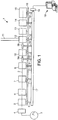
- Fig. 1 schematically shows a manufacturing apparatus 1 for the manufacture of an assembly of a blade and a blade support.
- Such an apparatus comprises a plurality of stations, which will be detailed thereafter, disposed along a path 2 materialized both by a straight line and dotted lines on Fig. 1 , in particular a linear, and more particularly a rectilinear path for a blade support material.
- the apparatus 1 comprises a delivery station 3 which delivers an elongated strip of blade support material, and, disposed along the path 2 in this order, the following stations :
- Most of these stations are disposed on a board 16 and are actuated by one or more respective actuators 5', 7', 8', 9a', 10', 9b', 12', 14', 15. For example, synchronization of the stations is ensured by connecting all these actuators to a common rotating shaft 17 driven by a servo-motor 18.
- inspection devices for example optical sensors or the like
- Such controls are connected to a remote monitoring station 19 such as for example, a micro computer, or the like, which also controls the operation of the motor 18.
- a remote monitoring station 19 such as for example, a micro computer, or the like, which also controls the operation of the motor 18.
- Some stations, such as for example, the bonding station, are not necessarily directly controlled by the shaft 17 but could be controlled directly by the monitoring station 19.
- the delivery station 3 for example comprises a reel rotatable about a rotation axis Y 3 , and delivering a strip of material which is to become a blade support for a razor blade head.
- the strip 34 is an elongated flat thin piece of rigid material, such as metal, in particular stainless steel.
- metal in particular stainless steel.
- it was obtained by cold rolling, annealing, and slitted to appropriate width from a base material of the following composition (in mass percentage) :
- Such material has a hardness of about 200-250 Hv1Kgf, and a tensile strength of about 760-960 N/mm 2 .
- its thickness t is about 0.27 mm (for example comprised between 0.22 and 0.32 mm, preferably between 0.275 and 0.285) and its height h of about 2.58 mm (for example comprised between 2.53 and 2.63).
- the frame of reference X-Y-Z is used to describe the geometry of the strip.
- X designates the length (the elongation direction) of the strip
- Y refers to the direction along which the strip is smallest (thickness direction)
- Z corresponds to the third direction of the strip, which is referred to as the height.
- the frame of reference X-Y-Z is a local frame of reference attached to the strip and can, for example, turn in the global room frame of reference (not shown) if the strip is rotated in the room for example in between two stations.
- the strip can arbitrarily be divided along its height (along direction Z) in an upper portion 39, a lower portion 35 and an intermediate portion 36 between the upper 39 and lower 35 portions.
- the upper portion 39 extends from a top side 46 downwards, and the lower portion 35 extends from the bottom side 47 upwards.
- a strip 34 has two opposite faces 48, 49, opposed with respect to direction Y, and which, at this stage of the process can, for example, be undifferentiated.
- the strip 34 is driven out of the delivery station 3 by continuous rotation of the reel, and by the stepwise movement of first displacement post 9a, as will be described in more details below.
- the strip passes through the loop control station 4, which is used to control the rotational speed of the reel 3.
- the strip 34 passes through a groove forming station 5, details of which are shown on Fig. 2 and 3 .
- the strip 34 is moved along longitudinal direction X between a groove forming roller 20 and a counter roller 21 which are disposed at the intermediate portion 36 of the strip and are controlled to rotate about the rotation axis Z 20 and Z 21 , both parallel to the axis Z.
- the outer surface 22 simply bears on the face 49 of the strip, without deforming it
- the outer surface 23 of the groove forming roller 20 is disposed so as to form a groove 50 in the face 48 of the strip 34 at the intermediate portion.
- the groove 50 is for example performed continuously and uninterruptedly in the strip 34 by material pressing. It can for example have a triangular cross-section, with symmetrical angled faces 50 1 and 50 2 with respect to a X-Y plane. Other geometries are possible. Material slitting is another groove-forming option.
- the geometry of the strip exiting from the groove forming station 5 is schematically shown on Fig. 19 , in section in the Y-Z plane.
- the actuator 5' controls the movement of the groove forming station 5, and in particular the rotation of the roller 20 about the axis Z 20 .
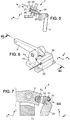
- the strip is then moved along the path 2 to the straightening station 6 which has been previously described and then to the notching station 7 shown on Fig. 4 .
- the actuator 7' is adapted to cause a notching device 24 to generate a notch through the strip 34 at a given rhythm. According to the present embodiment, this rhythm is selected so that a future individual blade support 134 will extend between two consecutive notches 51 in the strip.
- the notching device 24 will comprise a cylindrical seat 25 having an end 25' facing one of the faces 48, 49 of the strip (for example the face 48), and a piston 26 slidable with respect to the seat 25 along direction Y 7 in a back and forth movement actuated by the actuator 7'.
- the piston 26 comprises, at a notching head 26', a notching portion 27 adapted to perforate through the strip 34 where it is situated.
- the notch 51 will extend throughout the thickness of the strip 34 between the two faces 48 and 49. It extends from the top side 46 downward, but not reaching up to the bottom side 47. Further, the notch 51 will comprise a top short portion 52 extending from the top side 46 downward and a bottom long portion 53, longer than the short portion 52 along the axis X and extending from the top short portion 52 downward to the intermediate portion 36 of the strip 34.
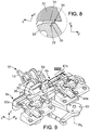
- the strip 34 is then moved to the bending station 8 shown in detail on Figs. 6 to 8 .
- the bending station 8 comprises a fixed receiving part 28 which comprises a slot 29 which receives the lower portion 35 of the strip 34 (see Fig. 8 ).
- the intermediate portion 36 and the upper portion 39 of the strip project outside of the slot 29.
- the bending station 8 further comprises a bending tool 30 which is rotatably mounted on the actuator 8' with respect to a rotation axis X 8 .
- the actuator 8' is mobile with respect to a support 79 about axis X 8 ' so as to cause the rotation of the bending tool 30 about the rotation axis X 8 between a neutral position (not shown) and a bending position, represented on Fig. 7 .
- the length of the bending tool 30 along the axis X (transverse to the plane of Fig. 7 ) is about the distance separating two notches 51.
- the bending tool 30 has a bending surface 31 which bears on the strip 34 so as to bend the strip between two successive notches 51 about axis X.
- the bending is performed so that the face 48 of the strip, which carries the groove 50 will be the inner face of the strip, whereas the outer face 49 will be the outer face.
- a bending could be performed with the groove 50 on the outer face of the strip.
- the bending is performed mainly at the intermediate portion 36 of the strip 34, so that the lower portion 35 remains substantially flat, and the upper portion 39 thereof also remains substantially flat, and angled with respect to the lower portion by an angle of about 60-76 degrees (about 68°).
- the resulting portion of the strip is shown on Fig. 22 .
- Fig. 22 shows a portion of the strip 34, which can be divided in three parts longitudinally along the axis X.
- the left hand side part 34 1 which is shown only partially, corresponds to a future blade support having not yet entered the bending station.
- the central part 34 2 is a future individual blade support located in the bending station, just after being submitted to the bending action of this station.
- the right hand side part 34 3 is a future individual blade support which has recently exited the bending station.
- the bending tool 30 could be subjected to a translative back and forth movement with respect to the receiving part 28.
- the longitudinal direction X remains the same as above.
- the direction U, or depth direction defines with direction X the plane of the upper surface 73 of the upper portion 39 of the bent strip 34.
- the direction V is the normal direction to the plane X-U.
- the notch 51 is also bent, the lowermost portion of the notch 71 remaining in the X-Z plane of the lower portion 35 of the strip, whereas the topmost portion of the notch 51 including the whole of portion 52, is located in the X-U plane of the upper portion 39.
- the longitudinal groove 50 is almost closed at this stage, its two angled surfaces 50 1 and 50 2 facing each other after bending.
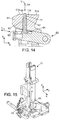
- Fig. 9 are schematically shown the first displacement post 9a, the separation station 10 and the second displacement post 9b.
- the first displacement post 9a comprises a grooved base 32a which comprises a groove 33 (see Fig. 11 ) in which the lower portion 35 of the strip is disposed, and aligned with the slot 29 of the receiving part 28 of the bending station (see Fig. 8 ), along axis X.
- the base 32 is made to move along the axis X 9a in a back-and-forth movement identified by arrow 37 on Fig. 10 on a receiving rail 38, which is fixed.
- the base 32 has longitudinal holes 40 extending along direction Y.
- a connection device 41a comprises a longitudinal body 42 and two side arms 43 (see Fig. 11 ) each extending in respective hole 40 of the base 32a.
- Each of these arms 43 has, at its end, an end pin 44 of a shape complementary with the notch 51 of the bent portion of the strip and in particular, with its bottom long portion 53.
- the connection device 41 is slidably mounted on the base 32a along direction Y 9a and can be submitted by an actuator to a back-and-forth movement along direction Y 9a between a position in which the end pin (guiding device) 44 extends in the notch (guided portion) 51 of the strip, thereby connecting together the base 32a and the strip 34, and a second position where the end pin 44 is removed from the notch 51 of the strip.
- the actuator 45a can comprise an actuating arm 54 which is adapted to perform a back-and-forth movement along direction Y 9a , as shown by arrow 55, for example actuated by a rotative arm 9a' rotative about the axis W 9a .
- the actuating arm will alternately press on the longitudinal body 42 to have the end of the arms 43 enter the notches 51, or release the body.
- the actuating arm 54 will be sufficiently long along direction X so as to impart the required movement along direction Y to the connection device 41a all along the displacement stroke of this device along direction X 9a .
- the end pin 44 Upon operation, the end pin 44 will be moved along direction Y 9a into two successive notches 51 of the strip 34.
- the base 32 will be moved along rail 38 along direction X 9a , thereby carrying the strip along direction X 9a by one stroke, corresponding to the spacing between two successive notches.
- the arms 43 of the connecting device 41a will be submitted to an opposite movement along direction Y 9a so as to free the strip from the base 32a, and the base 32a, will be moved in the opposite direction back to its initial position without carrying the strip 34.
- the strip is thus moved to the separation station 10 which comprises a grooved base 56 stationarily mounted on the rail 38, which comprises a groove 57 of similar shape, which receives therein the lower portion 35 of the strip, and a cutting device 58 which can be actuated by the actuator 10' so as to cut the strip when required.
- a separation portion 59 of the strip is defined, as shown on Fig. 23 by dotted lines between two supports, extending from the middle (along direction Z 10 ) of the bottom portion of the notch 51 downwards until the bottom side 47 of the strip.
- the cutting device 58 is thus synchronized with the apparatus to separate individual supports 134 from the strip 34 at the notch 51, by breaking the separation portion 59.
- the individual support 134 resulting from this cutting operation can be seen on Fig. 24 .
- Figure 24 shows a perspective view of an individual support.
- the individual bent support 134 comprises :
- the lower portion 135 of the bent support 134 extends longitudinally between two lateral portions 140.
- Each lateral portion includes a side edge 141 obtained at the separation station 10.
- the upper portion includes a side edge obtained at the notching station.
- the upper portion 139 of the bent support extends longitudinally between two lateral edges each including a rounded protrusion 142, which is constituted by a lateral wing with rounded angles protruding laterally from the upper portion 139.
- a rounded indent 143 separates the rounded protrusion 142 from the lateral edge 141 of the lower portion.
- the side edges 141 of the lower portion of the bent support protrude laterally from the rounded protrusions 142.
- the individual support 134 which is released from the strip of material 34 at the separation station 10 is, at this stage, handled alone by a second displacement post 9b, partly visible on Fig. 9 (see Fig. 12 ), which is similar to the first displacement post 9a. It thus also comprises a grooved base 32b similar to the grooved base 32a, having a groove which receives the lower portion 135 of the individual support and a similar mechanism of connecting device 41b and actuator 45b. Further, the first and second displacement posts can be synchronized by operation of a common disk 60 rotating about rotation axis W9.
- the base 32b displaces the individual support 134 along direction X to an assembly station 12 at which the individual support 134 is assembled to an individual corresponding razor blade 66, visible on Fig. 12 .
- the assembly station 12 comprises a grooved base 61 having a groove similar to the previously described grooves which receive the lower portion 135 of the individual support 134.
- individual razor blades 66 are provided from a blade delivery station 11 which for example comprises a stack of blades.
- the base 61 comprises a flat receiving surface 61a which extends parallel to the U-X plane, and thus receives the upper portion of the support 134.
- the grooved base 61 further comprises holes 62 which extend along the direction V and are suitable for receiving blade location pins 63.
- the blade location pins 63 can be actuated by an actuation mechanism 12' in a back-and-forth movement along direction V 12 , as shown by arrow 64 on Fig. 14 . As shown on Fig.
- the actuation mechanism 12' comprises an actuation arm 81 which is rotatable about axis W 12 to actuate a pin actuation device 82 which is slidable, with respect to the base 61 along a displacement axis T 12 in a back-and-forth movement, and has a connection surface 83 engaged with a complementary surface 84 of the blade locating pin to generate the movement of the blade locating pin 63 along axis V 12 .
- the blade location pin 63 is also rotated in a cam movement about axis V 12 during its movement up and down.
- the blade delivery station 11 comprises a pick-and-place apparatus 65 adapted to pick a razor blade 66 from a delivery station and to place it on the grooved base 61, for example using vacuum.
- vacuum can also be provided in the grooved base 61, through holes extending parallel to the holes 62 which receives the blade location pins 63, to maintain the blade 66 in position.
- the individual blade 66 comprises a front head portion 67 comprising a front edge 68, and a back handling portion 69.
- the back portion has parallel upper 69a and lower 69b faces.
- the lower face 69b is placed on the receiving surface 61a of the base 61.
- the back portion 69 is provided with two locating holes 70, which are for example located on both lateral sides of the blade 66.
- the geometry of the locating holes 70 is complementary to the geometry of the blade location pins 63. As shown on Fig.
- the blade 66 in operation, is precisely located with respect to the individual blade support 134 by the fact that the position of the groove 71 of the base 61, which receives the individual support 134, and the position of the blade location pins 63 are precisely relatively known.
- the blade 66 is precisely placed with its front portion 67 on the top surface of the platform portion of the support by the insertion of the locating holes 70 of the blade on the blade locating pins 63.
- the lower face 228 of the front portion 67 of the blade provides a fixation portion resting on the top face of the upper portion of the support 134.
- the blade and the blade support are located in the bonding station 13 which comprises means to permanently bind together the razor blade and the individual razor blade support 134.
- a laser 72 is used to assemble, by spot laser welding, the razor blade and the individual blade support 134 lying beneath at the bonding station 13.
- Fig. 25 is a cross sectional view of the assembly 80 of a blade 66 and a blade support 134 at this stage.
- the blade 66 has a front portion 67 which comprises a lower face 228 and a top face 227, substantially flat in a back portion, and which taper (comprising facets 231, 232), converging to a cutting edge 226.
- the lower face 228 of the blade is in contact with the upper face 73 of the upper portion 139 of the individual support 134 and is fixed thereto by a spot weld 74.
- the facets extend beyond the edge 146 of the support.
- the assembly 80 of the individual blade 66 and the individual support 134 is pushed along direction X to the next breaking station 14 by a next individual support moved to the bonding station 13 by the second displacement post 9b.
- the breaking station 14 is adapted to break the back portion 69 of the blade 66 so as to release a cutting member 124 consisting of the assembly of the individual support 134, and a cutting blade 125 sensibly corresponding to the front portion 67 of the blade 66.
- the breaking station 14 thus comprises a breaking tool 76 which can be submitted to a rotational movement about axis X14 by actuation of the actuator 14' so as to break the back portion 69 of the blade 66 away from the assembly.
- An aspiration device 77 can be provided to aspire these back portions 69 to scrap.
- the resulting cutting member 124 is shown on perspective on Fig. 26 and 27 . It comprises the individual support 134 having a lower portion 135, an upper portion 139 bent with respect to this lower portion at an intermediate portion (not visible) which comprises a longitudinal notch on its inner face. It further comprises a razor blade 125.
- the blade 125 is, in its flat portion, about 0.1 mm thick (for example between 0.04 (preferably 0.09) and 0.11 mm thick) and about 1.3 mm long along axis U from its cutting edge 126 to its opposite back edge (for example between 1.1 and 1.5 mm).
- the part, along axis U, of the blade, which is in contact with the top surface of the upper portion 139 of the blade support is about 0.9 mm +/-0.15 mm long.
- the cutting edge 126 is at least 0.35 mm away from the front edge 146 of the support, so that the support does not hinder the shaving performance of the neighbouring razor blades.
- the upper and lower faces 127, 128 of the blade include respectively the two parallel main surfaces 129, 130 and two tapered facets 131, 132 which taper towards the cutting edge 126.
- the upper portion 139 of the bent support extends longitudinally between two lateral edges each including the rounded protrusion 142 which is constituted by a lateral wing with rounded angles protruding laterally from the upper portion 139 and from a corresponding lateral end 133 of the blade.
- the rounded indent 143 cut out from the sheet metal forming the blade support separates the rounded protrusion 142 from the lateral edge 141 of the lower portion.
- the side edges 141 of the lower portion of the bent support protrude laterally from the lateral ends 133 of the blade and from the rounded protrusions 142.
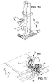
- the resulting cutting members 124 are displaced to a stacking station 15 (see Fig. 17 ) where they are stacked in a bayonet 78 for use in a razor head assembly process, for the manufacture of a razor head.
- the separation station 10 could be provided after the bonding station 13, or after the breaking station 14, before the stacking station 15.
- one or more of the stations are not necessarily provided in line with the rest of the apparatus.
- a first part of the process could be performed on a strip which is delivered by a delivery station such as a delivery station 3 of Fig. 1 , and rewound to a winding station.
- the reel carrying the partly formed strip could be then moved to a second apparatus for performing the other steps of the manufacturing process. This could, for example, be the case of the groove forming step.
- the blade support 134 differs from the previously described support in that it might comprise a recess 179 on the external face 49 in the intermediate bent portion 36.
- This recess could have a concave shape.
- This recess could be provided in addition to the groove 50 formed in the inner face 48.
- the recess 179 might for example be manufactured at the groove-forming station 6, by forming a groove similar to the groove 51 on the other side 49 of the strip, either by material slitting or pressing, either simultaneously or with rollers shifted along the X axis.
- Figure 29 shows a second embodiment for a blade support 134 according to the invention.
- the intermediate portion 36 is performed as a hinge between the top portion 139 of the support and the lower portion 135 of the support.
- the inner face 48, at the intermediate bent portion 136 has a radius of curvature of about 0.2 mm and the outer face 49 has a convex radius of curvature of about 0.38 mm.
- the hinge could be performed at the groove-forming station as described above in relation to the embodiment of Fig. 28 .
- the recess on the outer face 49 has a U-shaped cross-section, having a base 180 from each end of which extends a wing 181a, 181b, respectively connected to the outer face 49 of the top portion 139 and the bottom portion 135 of the support.
- a similar geometry 280, 281a, 281b, with a convex base, can be found on the inner face 49.
- Figure 30 shows a blade unit 105 for a safety razor (also called wet shaver), i.e. a shaver the blades of which are not driven by a motor relative to the blade unit.
- a safety razor also called wet shaver
- Such shavers typically include a handle extending in a longitudinal direction between a proximal portion and a distal portion bearing the blade unit 105 or shaving head.
- the longitudinal direction L may be curved or include one or several straight portions.
- the blade unit 105 includes an upper face equipped with one or several cutting members 124 and a lower face which is connected to the distal portion of the handle by a connection mechanism.
- the connection mechanism may for instance enable the blade unit 105 to pivot relative to a pivot axis which is substantially perpendicular to the longitudinal direction L. Said connection mechanism may further enable to selectively release the blade unit for the purpose of exchanging blade units.
- connection mechanism usable in the present invention is described in document WO-A-2006/027018 , which is hereby incorporated by reference in its entirety for all purposes.
- the blade unit 105 includes a frame 110 which is made solely of synthetic materials, i.e. thermoplastic materials (polystyrene or ABS, for example) and elastomeric materials.
- the frame 110 includes a plastic platform member 111 connected to the handle by the connection mechanism and having:
- the guard 112 is covered by an elastomeric layer 116 forming a plurality of fins 117 extending parallel to the pivot axis.
- the underside of the platform member 111 includes two shell bearings 118 which belong to the connection mechanism and which may be for example as described in the above-mentioned document WO-A-2006/027018 .
- the frame 110 further includes a plastic cover 119.
- the cover 119 exhibits a general U shape, with a cap portion 120 partially covering the cap portion 114 of the platform and two side members 121 covering the two side members 115 of the platform. In this embodiment, the cover 119 does not cover the guard 112 of the platform.
- the cap portion 120 of the cover 119 may include a lubricating strip 123 which is oriented upward and comes into contact with the skin of the user during shaving. This lubricating strip may be formed for instance by co-injection with the rest of the cover.
- At least one cutting member 124 is movably mounted in the blade receiving section 113 of the platform.
- the blade receiving section 113 may include several cutting members 124, for instance four cutting members as in the example shown in the drawings.
- Each cutting member 124 includes a blade 125 with its cutting edge 126 oriented forward in the direction of shaving.
- Each blade 125 has its upper face 127 oriented towards the skin to be shaved and a lower face 128 oriented toward the handle.
- Each blade 125 extends longitudinally, parallel to the pivot axis, between its two lateral ends 133.
- Each blade 125 is borne by a respective bent support 134.
- the bent support 134 comprises :
- the angle ⁇ of the upper portion 139 and of the blade 125 with respect to the shaving plane may be around 22°.
- the lower portion 135 of the bent support 134 extends longitudinally, parallel to the pivot axis, between the two lateral portions 140.
- each cutting member 134 is borne by two elastic fingers 144 which are molded as a single piece with the platform 111 and which extend towards each other and upwardly from both side members 115 of the platform.
- the end portions 140 of the bent supports are slidingly guided in vertical slots 145 (i.e. slots which are substantially perpendicular to the shaving plane) provided in the inner face of each side member 115 of the platform.
- the blade members 124 are elastically biased by the elastical arms 144 toward a rest position. In this rest position, the upper faces 127 of the blades, at each lateral end of the blades, bear against corresponding upper stop portions which are provided on the bottom face of each side member 121 of the cover, said side member 121 covering the slots 145 (not visible).
- the rest position of the blade members 124 is well defined, therefore enabling a high shaving precision.
Landscapes
- Engineering & Computer Science (AREA)
- Mechanical Engineering (AREA)
- Life Sciences & Earth Sciences (AREA)
- Forests & Forestry (AREA)
- Dry Shavers And Clippers (AREA)
- Packaging Of Annular Or Rod-Shaped Articles, Wearing Apparel, Cassettes, Or The Like (AREA)
- Knives (AREA)
- Nonmetal Cutting Devices (AREA)
- Treatment Of Fiber Materials (AREA)
Applications Claiming Priority (1)
| Application Number | Priority Date | Filing Date | Title |
|---|---|---|---|
| PCT/EP2008/067989 WO2010069388A1 (en) | 2008-12-19 | 2008-12-19 | Razor cartridge and mechanical razor comprising such a cartridge |
Publications (2)
| Publication Number | Publication Date |
|---|---|
| EP2376261A1 EP2376261A1 (en) | 2011-10-19 |
| EP2376261B1 true EP2376261B1 (en) | 2020-04-15 |
Family
ID=41210782
Family Applications (1)
| Application Number | Title | Priority Date | Filing Date |
|---|---|---|---|
| EP08875489.0A Active EP2376261B1 (en) | 2008-12-19 | 2008-12-19 | Razor cartridge and mechanical razor comprising such a cartridge |
Country Status (9)
| Country | Link |
|---|---|
| US (1) | US9156174B2 (ja) |
| EP (1) | EP2376261B1 (ja) |
| JP (1) | JP5815409B2 (ja) |
| KR (1) | KR101534791B1 (ja) |
| CN (1) | CN102300683B (ja) |
| BR (1) | BRPI0823367B1 (ja) |
| CA (1) | CA2745350C (ja) |
| MX (1) | MX338630B (ja) |
| WO (1) | WO2010069388A1 (ja) |
Families Citing this family (12)
| Publication number | Priority date | Publication date | Assignee | Title |
|---|---|---|---|---|
| US8011104B2 (en) * | 2006-04-10 | 2011-09-06 | The Gillette Company | Cutting members for shaving razors |
| US8336212B2 (en) * | 2006-06-20 | 2012-12-25 | Bic-Violex Sa | Razor blade unit |
| US7823272B2 (en) * | 2006-11-14 | 2010-11-02 | The Gillette Company | Systems for producing assemblies |
| PL2307188T5 (pl) * | 2008-07-18 | 2019-02-28 | Bic-Violex S.A. | Proces wytwarzania bezpiecznego wkładu do maszynki do golenia oraz bezpieczny wkład do maszynki do golenia |
| KR20100091622A (ko) * | 2009-02-11 | 2010-08-19 | 주식회사 도루코 | 일체형 카트리지 |
| CN102421572B (zh) * | 2009-04-15 | 2015-10-14 | 比克-维尔莱克 | 剃须刀刀架和包括该刀架的机械剃须刀 |
| EP2707180B1 (en) * | 2011-05-13 | 2016-12-14 | Edgewell Personal Care Brands, LLC | Razor blade supports |
| US9687893B2 (en) * | 2013-04-01 | 2017-06-27 | Hitachi Metals, Ltd. | Manufacturing method of martensite-based stainless steel for edged tools |
| US9762676B2 (en) * | 2014-09-26 | 2017-09-12 | Intel Corporation | Hardware resource access systems and techniques |
| WO2017103879A1 (en) * | 2015-12-17 | 2017-06-22 | Bic Violex S.A. | Shaving head |
| EP3357653B1 (en) | 2017-02-03 | 2021-11-10 | BIC-Violex S.A. | Blade support, cutting member comprising such a blade support, razor head comprising such a cutting member and mechanical shaving razor comprising such a razor head |
| EP3663033A1 (en) * | 2018-12-06 | 2020-06-10 | BIC-Violex S.A. | Laser welded razor blades |
Family Cites Families (35)
| Publication number | Priority date | Publication date | Assignee | Title |
|---|---|---|---|---|
| US4146958A (en) | 1976-10-15 | 1979-04-03 | Warner-Lambert Company | Safety razor |
| US5010646A (en) * | 1990-01-26 | 1991-04-30 | The Gillette Company | Shaving system |
| US5416974A (en) * | 1990-03-27 | 1995-05-23 | The Gillette Company | Safety razors and blade units therefor |
| GB9006782D0 (en) * | 1990-03-27 | 1990-05-23 | Gillette Co | Safety razors and blade units therefor |
| JPH0468768A (ja) | 1990-07-04 | 1992-03-04 | Ricoh Co Ltd | デジタル原稿読取装置 |
| US5067238A (en) | 1990-09-28 | 1991-11-26 | The Gillette Company | Shaving system |
| US5983499A (en) | 1995-06-07 | 1999-11-16 | Andrews; Edward A. | Cavity shaving device with curved razor blade strip |
| GB9320058D0 (en) | 1993-09-29 | 1993-11-17 | Gillette Co | Savety razors |
| US5661907A (en) | 1996-04-10 | 1997-09-02 | The Gillette Company | Razor blade assembly |
| GB9616402D0 (en) | 1996-08-05 | 1996-09-25 | Gillette Co | Safety razors |
| JPH11123458A (ja) * | 1997-10-27 | 1999-05-11 | Meiji Natl Ind Co Ltd | 金属板の折り曲げ構造 |
| US6629475B1 (en) | 2000-07-18 | 2003-10-07 | The Gillette Company | Razor blade |
| WO2004073939A1 (en) * | 2003-02-19 | 2004-09-02 | Eveready Battery Company, Inc. | Multiple blade razor cartridge |
| KR101123162B1 (ko) | 2003-06-26 | 2012-03-19 | 코닌클리케 필립스 일렉트로닉스 엔.브이. | 구부러진 면도기 날과 이러한 면도기 날의 제조 |
| JP2005052850A (ja) * | 2003-08-07 | 2005-03-03 | Toyo Kitchen & Living Co Ltd | 金属板の曲げ加工方法及び曲げ構造 |
| US7272991B2 (en) * | 2004-02-09 | 2007-09-25 | The Gillette Company | Shaving razors, and blade subassemblies therefor and methods of manufacture |
| US20050198837A1 (en) | 2004-03-11 | 2005-09-15 | Stephen Rawle | Shaving razors with multiple blades |
| US7669335B2 (en) | 2004-03-11 | 2010-03-02 | The Gillette Company | Shaving razors and shaving cartridges |
| US7131202B2 (en) | 2004-03-11 | 2006-11-07 | The Gillette Company | Cutting members for shaving razors with multiple blades |
| US7673541B2 (en) | 2004-06-03 | 2010-03-09 | The Gillette Company | Colored razor blades |
| PL1802428T3 (pl) * | 2004-09-24 | 2010-01-29 | Eveready Battery Inc | Urządzenie do golenia wyposażone w oddzielne segmenty wkładu z ostrzami |
| US7748121B2 (en) | 2005-05-06 | 2010-07-06 | Eveready Battery Company, Inc. | Razor blade and support assembly |
| JP4950507B2 (ja) * | 2006-02-14 | 2012-06-13 | 株式会社貝印刃物開発センター | 剃刀 |
| US8011104B2 (en) | 2006-04-10 | 2011-09-06 | The Gillette Company | Cutting members for shaving razors |
| US8499462B2 (en) | 2006-04-10 | 2013-08-06 | The Gillette Company | Cutting members for shaving razors |
| US8336212B2 (en) * | 2006-06-20 | 2012-12-25 | Bic-Violex Sa | Razor blade unit |
| KR100749925B1 (ko) | 2006-06-29 | 2007-08-16 | 주식회사 도루코 | 면도기 |
| US8443519B2 (en) | 2006-09-15 | 2013-05-21 | The Gillette Company | Blade supports for use in shaving systems |
| US7823272B2 (en) | 2006-11-14 | 2010-11-02 | The Gillette Company | Systems for producing assemblies |
| EP2114637A1 (de) | 2007-02-01 | 2009-11-11 | Braun GmbH | Haarentfernungsgerät |
| KR20100083161A (ko) * | 2007-11-02 | 2010-07-21 | 더 질레트 컴퍼니 | 습식 면도기 |
| AU2009244489B2 (en) | 2008-05-05 | 2015-05-07 | Edgewell Personal Care Brands, Llc | Razor blade and method of manufacture |
| AU2009296283A1 (en) | 2008-09-29 | 2010-04-01 | The Gillette Company | Razor cartridges with perforated blade assemblies |
| RU2008150012A (ru) | 2008-12-10 | 2010-06-20 | Александр Тарасович Володин (RU) | Лезвийный блок безопасной бритвы |
| KR101055684B1 (ko) | 2009-02-11 | 2011-08-09 | 주식회사 도루코 | 일체형 면도날 및 이를 이용한 면도기 카트리지 |
-
2008
- 2008-12-19 JP JP2011541104A patent/JP5815409B2/ja active Active
- 2008-12-19 EP EP08875489.0A patent/EP2376261B1/en active Active
- 2008-12-19 CA CA2745350A patent/CA2745350C/en active Active
- 2008-12-19 WO PCT/EP2008/067989 patent/WO2010069388A1/en active Application Filing
- 2008-12-19 US US13/139,191 patent/US9156174B2/en active Active
- 2008-12-19 MX MX2011006662A patent/MX338630B/es active IP Right Grant
- 2008-12-19 BR BRPI0823367A patent/BRPI0823367B1/pt active IP Right Grant
- 2008-12-19 CN CN200880132758.3A patent/CN102300683B/zh active Active
- 2008-12-19 KR KR1020117016449A patent/KR101534791B1/ko active IP Right Grant
Non-Patent Citations (1)
| Title |
|---|
| None * |
Also Published As
| Publication number | Publication date |
|---|---|
| CN102300683A (zh) | 2011-12-28 |
| US9156174B2 (en) | 2015-10-13 |
| BRPI0823367A2 (pt) | 2015-06-16 |
| CA2745350A1 (en) | 2010-06-24 |
| KR20110114576A (ko) | 2011-10-19 |
| CN102300683B (zh) | 2014-10-22 |
| MX338630B (es) | 2016-04-26 |
| EP2376261A1 (en) | 2011-10-19 |
| BRPI0823367B1 (pt) | 2020-04-07 |
| US20120011725A1 (en) | 2012-01-19 |
| JP2012511973A (ja) | 2012-05-31 |
| JP5815409B2 (ja) | 2015-11-17 |
| MX2011006662A (es) | 2011-08-03 |
| WO2010069388A1 (en) | 2010-06-24 |
| CA2745350C (en) | 2017-05-30 |
| KR101534791B1 (ko) | 2015-07-07 |
Similar Documents
| Publication | Publication Date | Title |
|---|---|---|
| EP2376261B1 (en) | Razor cartridge and mechanical razor comprising such a cartridge | |
| EP2419247B1 (en) | Method of manufacturing a razor head component, support obtained thereby and razor cartridge and razor comprising said support | |
| EP2373444B1 (en) | Method and apparatus for the manufacture of razor head component | |
| US20180194025A1 (en) | Razor blade, razor head, and method of manufacture | |
| EP3378614B1 (en) | Razor blade, razor head, and method of manufacture |
Legal Events
| Date | Code | Title | Description |
|---|---|---|---|
| PUAI | Public reference made under article 153(3) epc to a published international application that has entered the european phase |
Free format text: ORIGINAL CODE: 0009012 |
|
| 17P | Request for examination filed |
Effective date: 20110601 |
|
| AK | Designated contracting states |
Kind code of ref document: A1 Designated state(s): AT BE BG CH CY CZ DE DK EE ES FI FR GB GR HR HU IE IS IT LI LT LU LV MC MT NL NO PL PT RO SE SI SK TR |
|
| DAX | Request for extension of the european patent (deleted) | ||
| STAA | Information on the status of an ep patent application or granted ep patent |
Free format text: STATUS: EXAMINATION IS IN PROGRESS |
|
| 17Q | First examination report despatched |
Effective date: 20171017 |
|
| RIC1 | Information provided on ipc code assigned before grant |
Ipc: B26B 21/22 20060101AFI20190923BHEP Ipc: B26B 21/56 20060101ALI20190923BHEP Ipc: B26B 21/40 20060101ALI20190923BHEP |
|
| GRAP | Despatch of communication of intention to grant a patent |
Free format text: ORIGINAL CODE: EPIDOSNIGR1 |
|
| STAA | Information on the status of an ep patent application or granted ep patent |
Free format text: STATUS: GRANT OF PATENT IS INTENDED |
|
| INTG | Intention to grant announced |
Effective date: 20191113 |
|
| GRAS | Grant fee paid |
Free format text: ORIGINAL CODE: EPIDOSNIGR3 |
|
| GRAA | (expected) grant |
Free format text: ORIGINAL CODE: 0009210 |
|
| STAA | Information on the status of an ep patent application or granted ep patent |
Free format text: STATUS: THE PATENT HAS BEEN GRANTED |
|
| AK | Designated contracting states |
Kind code of ref document: B1 Designated state(s): AT BE BG CH CY CZ DE DK EE ES FI FR GB GR HR HU IE IS IT LI LT LU LV MC MT NL NO PL PT RO SE SI SK TR |
|
| REG | Reference to a national code |
Ref country code: GB Ref legal event code: FG4D Ref country code: CH Ref legal event code: EP |
|
| REG | Reference to a national code |
Ref country code: DE Ref legal event code: R096 Ref document number: 602008062526 Country of ref document: DE |
|
| REG | Reference to a national code |
Ref country code: IE Ref legal event code: FG4D |
|
| REG | Reference to a national code |
Ref country code: AT Ref legal event code: REF Ref document number: 1256716 Country of ref document: AT Kind code of ref document: T Effective date: 20200515 |
|
| REG | Reference to a national code |
Ref country code: NL Ref legal event code: MP Effective date: 20200415 |
|
| REG | Reference to a national code |
Ref country code: LT Ref legal event code: MG4D |
|
| PG25 | Lapsed in a contracting state [announced via postgrant information from national office to epo] |
Ref country code: FI Free format text: LAPSE BECAUSE OF FAILURE TO SUBMIT A TRANSLATION OF THE DESCRIPTION OR TO PAY THE FEE WITHIN THE PRESCRIBED TIME-LIMIT Effective date: 20200415 Ref country code: SE Free format text: LAPSE BECAUSE OF FAILURE TO SUBMIT A TRANSLATION OF THE DESCRIPTION OR TO PAY THE FEE WITHIN THE PRESCRIBED TIME-LIMIT Effective date: 20200415 Ref country code: NO Free format text: LAPSE BECAUSE OF FAILURE TO SUBMIT A TRANSLATION OF THE DESCRIPTION OR TO PAY THE FEE WITHIN THE PRESCRIBED TIME-LIMIT Effective date: 20200715 Ref country code: GR Free format text: LAPSE BECAUSE OF FAILURE TO SUBMIT A TRANSLATION OF THE DESCRIPTION OR TO PAY THE FEE WITHIN THE PRESCRIBED TIME-LIMIT Effective date: 20200716 Ref country code: PT Free format text: LAPSE BECAUSE OF FAILURE TO SUBMIT A TRANSLATION OF THE DESCRIPTION OR TO PAY THE FEE WITHIN THE PRESCRIBED TIME-LIMIT Effective date: 20200817 Ref country code: LT Free format text: LAPSE BECAUSE OF FAILURE TO SUBMIT A TRANSLATION OF THE DESCRIPTION OR TO PAY THE FEE WITHIN THE PRESCRIBED TIME-LIMIT Effective date: 20200415 Ref country code: NL Free format text: LAPSE BECAUSE OF FAILURE TO SUBMIT A TRANSLATION OF THE DESCRIPTION OR TO PAY THE FEE WITHIN THE PRESCRIBED TIME-LIMIT Effective date: 20200415 Ref country code: IS Free format text: LAPSE BECAUSE OF FAILURE TO SUBMIT A TRANSLATION OF THE DESCRIPTION OR TO PAY THE FEE WITHIN THE PRESCRIBED TIME-LIMIT Effective date: 20200815 |
|
| REG | Reference to a national code |
Ref country code: AT Ref legal event code: MK05 Ref document number: 1256716 Country of ref document: AT Kind code of ref document: T Effective date: 20200415 |
|
| PG25 | Lapsed in a contracting state [announced via postgrant information from national office to epo] |
Ref country code: BG Free format text: LAPSE BECAUSE OF FAILURE TO SUBMIT A TRANSLATION OF THE DESCRIPTION OR TO PAY THE FEE WITHIN THE PRESCRIBED TIME-LIMIT Effective date: 20200715 Ref country code: LV Free format text: LAPSE BECAUSE OF FAILURE TO SUBMIT A TRANSLATION OF THE DESCRIPTION OR TO PAY THE FEE WITHIN THE PRESCRIBED TIME-LIMIT Effective date: 20200415 Ref country code: HR Free format text: LAPSE BECAUSE OF FAILURE TO SUBMIT A TRANSLATION OF THE DESCRIPTION OR TO PAY THE FEE WITHIN THE PRESCRIBED TIME-LIMIT Effective date: 20200415 |
|
| REG | Reference to a national code |
Ref country code: DE Ref legal event code: R097 Ref document number: 602008062526 Country of ref document: DE |
|
| PG25 | Lapsed in a contracting state [announced via postgrant information from national office to epo] |
Ref country code: IT Free format text: LAPSE BECAUSE OF FAILURE TO SUBMIT A TRANSLATION OF THE DESCRIPTION OR TO PAY THE FEE WITHIN THE PRESCRIBED TIME-LIMIT Effective date: 20200415 Ref country code: DK Free format text: LAPSE BECAUSE OF FAILURE TO SUBMIT A TRANSLATION OF THE DESCRIPTION OR TO PAY THE FEE WITHIN THE PRESCRIBED TIME-LIMIT Effective date: 20200415 Ref country code: AT Free format text: LAPSE BECAUSE OF FAILURE TO SUBMIT A TRANSLATION OF THE DESCRIPTION OR TO PAY THE FEE WITHIN THE PRESCRIBED TIME-LIMIT Effective date: 20200415 Ref country code: RO Free format text: LAPSE BECAUSE OF FAILURE TO SUBMIT A TRANSLATION OF THE DESCRIPTION OR TO PAY THE FEE WITHIN THE PRESCRIBED TIME-LIMIT Effective date: 20200415 Ref country code: CZ Free format text: LAPSE BECAUSE OF FAILURE TO SUBMIT A TRANSLATION OF THE DESCRIPTION OR TO PAY THE FEE WITHIN THE PRESCRIBED TIME-LIMIT Effective date: 20200415 Ref country code: ES Free format text: LAPSE BECAUSE OF FAILURE TO SUBMIT A TRANSLATION OF THE DESCRIPTION OR TO PAY THE FEE WITHIN THE PRESCRIBED TIME-LIMIT Effective date: 20200415 Ref country code: EE Free format text: LAPSE BECAUSE OF FAILURE TO SUBMIT A TRANSLATION OF THE DESCRIPTION OR TO PAY THE FEE WITHIN THE PRESCRIBED TIME-LIMIT Effective date: 20200415 |
|
| PLBE | No opposition filed within time limit |
Free format text: ORIGINAL CODE: 0009261 |
|
| STAA | Information on the status of an ep patent application or granted ep patent |
Free format text: STATUS: NO OPPOSITION FILED WITHIN TIME LIMIT |
|
| PG25 | Lapsed in a contracting state [announced via postgrant information from national office to epo] |
Ref country code: SK Free format text: LAPSE BECAUSE OF FAILURE TO SUBMIT A TRANSLATION OF THE DESCRIPTION OR TO PAY THE FEE WITHIN THE PRESCRIBED TIME-LIMIT Effective date: 20200415 Ref country code: PL Free format text: LAPSE BECAUSE OF FAILURE TO SUBMIT A TRANSLATION OF THE DESCRIPTION OR TO PAY THE FEE WITHIN THE PRESCRIBED TIME-LIMIT Effective date: 20200415 |
|
| 26N | No opposition filed |
Effective date: 20210118 |
|
| PG25 | Lapsed in a contracting state [announced via postgrant information from national office to epo] |
Ref country code: SI Free format text: LAPSE BECAUSE OF FAILURE TO SUBMIT A TRANSLATION OF THE DESCRIPTION OR TO PAY THE FEE WITHIN THE PRESCRIBED TIME-LIMIT Effective date: 20200415 |
|
| REG | Reference to a national code |
Ref country code: CH Ref legal event code: PL |
|
| PG25 | Lapsed in a contracting state [announced via postgrant information from national office to epo] |
Ref country code: MC Free format text: LAPSE BECAUSE OF FAILURE TO SUBMIT A TRANSLATION OF THE DESCRIPTION OR TO PAY THE FEE WITHIN THE PRESCRIBED TIME-LIMIT Effective date: 20200415 |
|
| REG | Reference to a national code |
Ref country code: BE Ref legal event code: MM Effective date: 20201231 |
|
| PG25 | Lapsed in a contracting state [announced via postgrant information from national office to epo] |
Ref country code: IE Free format text: LAPSE BECAUSE OF NON-PAYMENT OF DUE FEES Effective date: 20201219 Ref country code: LU Free format text: LAPSE BECAUSE OF NON-PAYMENT OF DUE FEES Effective date: 20201219 |
|
| PG25 | Lapsed in a contracting state [announced via postgrant information from national office to epo] |
Ref country code: LI Free format text: LAPSE BECAUSE OF NON-PAYMENT OF DUE FEES Effective date: 20201231 Ref country code: CH Free format text: LAPSE BECAUSE OF NON-PAYMENT OF DUE FEES Effective date: 20201231 |
|
| PG25 | Lapsed in a contracting state [announced via postgrant information from national office to epo] |
Ref country code: TR Free format text: LAPSE BECAUSE OF FAILURE TO SUBMIT A TRANSLATION OF THE DESCRIPTION OR TO PAY THE FEE WITHIN THE PRESCRIBED TIME-LIMIT Effective date: 20200415 Ref country code: MT Free format text: LAPSE BECAUSE OF FAILURE TO SUBMIT A TRANSLATION OF THE DESCRIPTION OR TO PAY THE FEE WITHIN THE PRESCRIBED TIME-LIMIT Effective date: 20200415 Ref country code: CY Free format text: LAPSE BECAUSE OF FAILURE TO SUBMIT A TRANSLATION OF THE DESCRIPTION OR TO PAY THE FEE WITHIN THE PRESCRIBED TIME-LIMIT Effective date: 20200415 |
|
| PG25 | Lapsed in a contracting state [announced via postgrant information from national office to epo] |
Ref country code: BE Free format text: LAPSE BECAUSE OF NON-PAYMENT OF DUE FEES Effective date: 20201231 |
|
| PGFP | Annual fee paid to national office [announced via postgrant information from national office to epo] |
Ref country code: GB Payment date: 20231124 Year of fee payment: 16 |
|
| PGFP | Annual fee paid to national office [announced via postgrant information from national office to epo] |
Ref country code: FR Payment date: 20231122 Year of fee payment: 16 Ref country code: DE Payment date: 20231121 Year of fee payment: 16 |