EP2375871A2 - Verfahren zur Lichtsteuerung und Lichtsteuersystem - Google Patents
Verfahren zur Lichtsteuerung und Lichtsteuersystem Download PDFInfo
- Publication number
- EP2375871A2 EP2375871A2 EP11161523A EP11161523A EP2375871A2 EP 2375871 A2 EP2375871 A2 EP 2375871A2 EP 11161523 A EP11161523 A EP 11161523A EP 11161523 A EP11161523 A EP 11161523A EP 2375871 A2 EP2375871 A2 EP 2375871A2
- Authority
- EP
- European Patent Office
- Prior art keywords
- values
- control
- luminaires
- calculated
- brightness
- Prior art date
- Legal status (The legal status is an assumption and is not a legal conclusion. Google has not performed a legal analysis and makes no representation as to the accuracy of the status listed.)
- Granted
Links
Images


Classifications
-
- H—ELECTRICITY
- H05—ELECTRIC TECHNIQUES NOT OTHERWISE PROVIDED FOR
- H05B—ELECTRIC HEATING; ELECTRIC LIGHT SOURCES NOT OTHERWISE PROVIDED FOR; CIRCUIT ARRANGEMENTS FOR ELECTRIC LIGHT SOURCES, IN GENERAL
- H05B47/00—Circuit arrangements for operating light sources in general, i.e. where the type of light source is not relevant
- H05B47/10—Controlling the light source
- H05B47/105—Controlling the light source in response to determined parameters
- H05B47/11—Controlling the light source in response to determined parameters by determining the brightness or colour temperature of ambient light
-
- Y—GENERAL TAGGING OF NEW TECHNOLOGICAL DEVELOPMENTS; GENERAL TAGGING OF CROSS-SECTIONAL TECHNOLOGIES SPANNING OVER SEVERAL SECTIONS OF THE IPC; TECHNICAL SUBJECTS COVERED BY FORMER USPC CROSS-REFERENCE ART COLLECTIONS [XRACs] AND DIGESTS
- Y02—TECHNOLOGIES OR APPLICATIONS FOR MITIGATION OR ADAPTATION AGAINST CLIMATE CHANGE
- Y02B—CLIMATE CHANGE MITIGATION TECHNOLOGIES RELATED TO BUILDINGS, e.g. HOUSING, HOUSE APPLIANCES OR RELATED END-USER APPLICATIONS
- Y02B20/00—Energy efficient lighting technologies, e.g. halogen lamps or gas discharge lamps
- Y02B20/40—Control techniques providing energy savings, e.g. smart controller or presence detection
Definitions
- the present invention relates to a method for light control, in which a plurality of luminaires are to be controlled in order to achieve predetermined brightness values in a plurality of areas to be illuminated. Furthermore, the present invention relates to a corresponding system for carrying out the method according to the invention.
- the present invention has for its object to provide a novel possibility for light control, which solves the above problem, while suppressing the occurrence of brightness variations as possible.
- the solution according to the invention is based on the idea of not making a classical regulation of the brightnesses. Instead, suitable control values for the luminaire are calculated and transmitted to the luminaires only after the calculations have been completed. As will be explained in more detail below, this can be avoided as the unpleasant transient response.
- the aforementioned steps b) and c) can be repeated if the deviations of the actually resulting brightness values from the desired values exceed a certain threshold or limit.
- the calculation of the manipulated variables in the abovementioned step b) is preferably carried out in two sub-steps, wherein in a first sub-step the manipulated values are calculated in such a way that the calculated or theoretical brightness values respectively lie between an upper and a lower desired value. In a second step then the manipulated variables are modified in such a way that the calculated brightness values approach each other as well as possible to the lower setpoint values. In the first step, care is taken to ensure that the lighting requirements are met as a whole. With the second step of approaching the lower setpoints, an energetic optimization is achieved, ie the total power consumption is reduced.
- the control values are preferably calculated in the context of an iteration method, wherein the control values are transmitted to the luminaires only after completion of the iteration process.
- the individual iteration steps are carried out on the basis of a simulation calculation of the system, for which purpose it is possible, for example, to resort to data obtained in an initialization process of the system. However, this information may be updated at any time as the system continues to operate. If, for example, it should turn out that there are deviations from the setpoints after the control values have been transmitted to the luminaires, these can be taken into account when simulating the system at a later time.
- the process is further optimized in a self-learning process. Also, changes in the light output of the lights, which are due to thermal fluctuations, but especially due to aging, can be considered and compensated in this way.
- suitable setting values for the luminaire can be determined in a fast and reliable manner without unwanted light fluctuations occurring when the luminaires are activated.
- FIG. 1 Shown is a room 100 from two different views, in which three lights 107, 108 and 109 are arranged to illuminate different areas. External light can also fall into the room 100 through a window 101.
- a table 105 Within the space 100 is a table 105 with a work surface 106.
- Different areas of the room 100 should now be illuminated in different ways with the aid of the lights 107 to 109.
- a first area A which forms the working surface 106 of the table 105
- a second area B located near an entrance door 102 should be illuminated at a lower brightness.
- a region C on the wall in a targeted manner with a very high brightness in order, for example, to illuminate an object arranged in this region of the wall.
- Three different areas A, B and C of the room 100 should therefore be illuminated in different ways with the aid of the three lights 107 to 109.
- suitable control values for the luminaires 107 to 109 must be found in order to solve this problem.
- the present invention is not limited to those systems in which the number of different areas to be illuminated corresponds exactly to the number of luminaires.
- the number m of the different surfaces or areas may well also be of the number n of the lights, the number of lights can be both larger and smaller than the number of areas to be illuminated.
- a sensor 120 which will be described in more detail below, is arranged on the ceiling of the room and generates suitable control information.
- the sensor 120 detects the brightness actual values in the three areas A, B, C. These are transmitted to a control unit 110, which then performs a suitable control of the lights 107 to 109.
- a first step the method illustrated is to determine the brightness actual values in the areas A, B and C with the aid of the aforementioned sensor or a plurality of sensors 120.
- this first step 10 therefore, the current state of the system is detected.
- the central step 11 of the method follows, in which suitable setting values for the luminaires are calculated on the basis of the actual brightness values such that the totality of the deviations of the calculated brightness values for the areas from the set values reaches a minimum.
- the control values are transmitted to the lights in step 12.
- step 13 a check can take place, in which case the brightness actual values are again detected and compared with the desired values. If it turns out that the deviations exceed a certain threshold or limit, the steps 11 and 12 can be repeated, ie at the time t 2 corrected control values are transmitted to the lights, so that now the brightness value H 2 results. If, during the subsequent check 13, it is determined that the brightness actual values now match the setpoints sufficiently well, the method is ended.
- the calculation of the control values in step 11 is preferably carried out by using an iterative optimization algorithm. It is provided in particular that the behavior of the system is predicted by a simulation calculation after each iteration step. Only when the system has settled in this mathematical simulation, the control values are transferred to the lights. This procedure leads very effectively to the desired results. When carrying out the simulation calculation, it is possible in particular to resort to earlier findings of the behavior of the system. These findings or information can be obtained, for example, in the context of an initialization of the system. The control unit controls the various lights at different control values and records and analyzes the resulting changes in the lighting in the various areas. Furthermore, the findings in the context of the review step 13 can also be taken into account.
- the simulation model can be suitably adapted in order to obtain better results when the method is carried out at a later time. In this way, a self-learning system is virtually formed, which is suitable for effectively calculating the required control values.
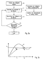
- a development of the method, in particular the calculation step 11 is schematically in FIG. 4 shown.
- the calculation of the manipulated variables is subdivided into temporally two consecutive phases.
- a calculation of the control values takes place in such a way that the calculated brightness values proceed from the actual state (represented by x) to a first calculated value. Care is taken that this first calculated value (represented by o) is within a setpoint corridor defined by an upper setpoint S o and a lower setpoint S u .
- the manipulated variables are calculated in such a way that all predicted brightness values lie between the two setpoints. In this way, it should first be ensured that the light quality, ie the lighting achieved, corresponds to the requirements defined by the setpoints.
- control values are then further optimized so that the final calculated or predicted brightness values (represented by annäh) approximate to the lower setpoint value, in particular come as close as possible to this setpoint value. This ultimately means that the individual brightness values are reduced as much as possible within the allowable range, which ultimately results in reduced energy consumption. Also in this case, of course, a transmission of the control values to the lights is made only after completion of the second phase.
- control values for anti-glare devices in particular the blind located on the window 101, could also be determined in this context.
- the influence of this blind can also be taken into account in the simulation calculation.
- FIG. 5 a particularly preferred embodiment of a light control system is shown schematically, which is used to carry out the method.
- the peculiarity consists in particular in the design of the sensor 120, which is able to detect the brightness actual values of several areas.
- the sensor 120 has an imaging digital sensor 10 with an associated optical system 11. That is, the sensor 120 ideally captures an image of the entire space (which, for example, is shown in FIG. 2 corresponds) and analyzes the corresponding image data to obtain the desired actual values.
- the digital image data can in this case first be processed by a further unit 12 in a suitable manner. Subsequently, an image data processing unit 13 then analyzes those data which are assigned to the areas A, B and C to be evaluated.
- a single sensor unit 120 can be used to obtain the required information regarding the current state of the system.
- This control information is then transmitted to the control unit 110, which calculates in the manner described above based on these data set values for the lights and blinds or generally for the actuators and transmitted to this.
- the setpoint values for the individual regions can be predetermined, for example, by manual input devices 111, which are likewise connected to the control unit 110.
- individual sensors instead of the multifunctional sensor unit described above. The operation of the control unit would not be affected thereby, as it is irrelevant for them, whether the control information or the actual values for the brightnesses in the individual areas are supplied by a single unit or multiple sensors.
Landscapes
- Circuit Arrangement For Electric Light Sources In General (AREA)
Applications Claiming Priority (1)
| Application Number | Priority Date | Filing Date | Title |
|---|---|---|---|
| DE102010003803A DE102010003803A1 (de) | 2010-04-09 | 2010-04-09 | Verfahren zur Lichtsteuerung und Lichtsteuersystem |
Publications (3)
| Publication Number | Publication Date |
|---|---|
| EP2375871A2 true EP2375871A2 (de) | 2011-10-12 |
| EP2375871A3 EP2375871A3 (de) | 2016-08-31 |
| EP2375871B1 EP2375871B1 (de) | 2017-09-13 |
Family
ID=44343748
Family Applications (1)
| Application Number | Title | Priority Date | Filing Date |
|---|---|---|---|
| EP11161523.3A Active EP2375871B1 (de) | 2010-04-09 | 2011-04-07 | Verfahren zur Lichtsteuerung und Lichtsteuersystem |
Country Status (2)
| Country | Link |
|---|---|
| EP (1) | EP2375871B1 (it) |
| DE (1) | DE102010003803A1 (it) |
Cited By (2)
| Publication number | Priority date | Publication date | Assignee | Title |
|---|---|---|---|---|
| CN106982505A (zh) * | 2017-05-19 | 2017-07-25 | 北京同步科技有限公司 | 灯光的智能开环调试系统及其调试方法 |
| AT518823A1 (de) * | 2016-07-04 | 2018-01-15 | Bernecker + Rainer Industrie-Elektronik Ges M B H | Beleuchtungsanordnung für die industrielle Bildverarbeitung |
Citations (2)
| Publication number | Priority date | Publication date | Assignee | Title |
|---|---|---|---|---|
| EP0652690A1 (fr) * | 1993-11-09 | 1995-05-10 | Laboratoires D'electronique Philips S.A.S. | Dispositif de commande automatique d'éclairage |
| WO2008001259A2 (en) * | 2006-06-28 | 2008-01-03 | Philips Intellectual Property & Standards Gmbh | Method of controlling a lighting system based on a target light distribution |
Family Cites Families (3)
| Publication number | Priority date | Publication date | Assignee | Title |
|---|---|---|---|---|
| DE19619281A1 (de) * | 1996-05-13 | 1997-11-20 | Zumtobel Licht | System und Steuereinrichtung zum Steuern der Helligkeit eines Raumes |
| DE19842465A1 (de) * | 1998-09-16 | 2000-03-23 | Siemens Ag | Verfahren zur Konstantlichtregelung |
| DE102004047962A1 (de) * | 2004-10-01 | 2006-04-06 | Patent-Treuhand-Gesellschaft für elektrische Glühlampen mbH | Sensorsystem |
-
2010
- 2010-04-09 DE DE102010003803A patent/DE102010003803A1/de not_active Withdrawn
-
2011
- 2011-04-07 EP EP11161523.3A patent/EP2375871B1/de active Active
Patent Citations (2)
| Publication number | Priority date | Publication date | Assignee | Title |
|---|---|---|---|---|
| EP0652690A1 (fr) * | 1993-11-09 | 1995-05-10 | Laboratoires D'electronique Philips S.A.S. | Dispositif de commande automatique d'éclairage |
| WO2008001259A2 (en) * | 2006-06-28 | 2008-01-03 | Philips Intellectual Property & Standards Gmbh | Method of controlling a lighting system based on a target light distribution |
Cited By (3)
| Publication number | Priority date | Publication date | Assignee | Title |
|---|---|---|---|---|
| AT518823A1 (de) * | 2016-07-04 | 2018-01-15 | Bernecker + Rainer Industrie-Elektronik Ges M B H | Beleuchtungsanordnung für die industrielle Bildverarbeitung |
| US10390412B2 (en) | 2016-07-04 | 2019-08-20 | B&R Industrial Automation GmbH | Lighting arrangement for industrial image processing |
| CN106982505A (zh) * | 2017-05-19 | 2017-07-25 | 北京同步科技有限公司 | 灯光的智能开环调试系统及其调试方法 |
Also Published As
| Publication number | Publication date |
|---|---|
| EP2375871B1 (de) | 2017-09-13 |
| DE102010003803A1 (de) | 2011-10-13 |
| EP2375871A3 (de) | 2016-08-31 |
Similar Documents
| Publication | Publication Date | Title |
|---|---|---|
| EP2560464A1 (de) | Verfahren zur Steuerung und Regelung eines Lichtsystems | |
| DE19619281A1 (de) | System und Steuereinrichtung zum Steuern der Helligkeit eines Raumes | |
| EP2835037B1 (de) | Verfahren und vorrichtung zum regeln einer beleuchtungsstärke, mit adaptivem regelkreis-faktor | |
| DE102010003804A1 (de) | Multifunktionale Sensoreinheit zum Ermitteln von Kontrollinformationen für die Lichtsteuerung | |
| EP3142464B1 (de) | Beleuchtungssystem | |
| EP2375871B1 (de) | Verfahren zur Lichtsteuerung und Lichtsteuersystem | |
| EP3251469B1 (de) | Verfahren zum betreiben von geräten in einem beleuchtungssystem | |
| EP2202596B1 (de) | Anordnung bestehend aus einer programmgesteuerten Einheit und einem mit dieser verbundenen Power-Baustein | |
| EP2288969B1 (de) | Leitsystem einer anlage mit mehrstufiger modelloptimierung | |
| DE102013212789A1 (de) | Beleuchtungssystem und Leuchte mit Notlichtfunktion | |
| EP2732541B1 (de) | Anordnung mit potenzialgetrennter stromversorgungseinrichtung | |
| EP2475227B1 (de) | Beleuchtungssytem mit mehreren Leuchten und Gerät zur Umsetzung von Stellwerten | |
| DE102012210959A1 (de) | Steuerungssystem für verteilt angeordnete Verbraucher und Verfahren zur Inbetriebnahme des Systems | |
| EP2375870B1 (de) | Verfahren und System zur Lichtsteuerung | |
| DE4343017A1 (de) | Verfahren zum Einstellen des Summenlichts in einem Raum und Vorrichtung zur Durchführung des Verfahrens | |
| EP3217765A1 (de) | Vereinfachtes inbetriebnahmekonzept zum ansteuern von aktoren einer gebäudeinstallation | |
| EP2984904B1 (de) | Verfahren zum ansteuern einer leuchte mit mehreren teileinheiten | |
| DE3221873C2 (de) | Verfahren und Anordnung zur Reduzierung des Energieverbrauchs einer Bühnenstellanlage | |
| DE102015216362A1 (de) | Kommunizierende Scheinwerfer mehrerer Fahrzeuge | |
| WO2016050599A1 (de) | Verfahren zum ermitteln des energiebedarfs einer produktionsmaschine oder eines aus mehreren produktionsmaschinen bestehenden produktionssystems sowie zur durchführung des verfahrens geeignetes messgerät | |
| DE10359412B4 (de) | Verfahren zum Berechnen einer Übergangskurve zum Überführen einer Regelgröße von einem Anfangswert in einen Endwert | |
| WO2021058502A1 (de) | Regelung eines robotermanipulators | |
| DE4216699A1 (de) | Verfahren und Einrichtung zum automatischen Schutz einer Anlage, insbesondere eines Kernkraftwerks | |
| AT16014U1 (de) | Betriebsgerät zum Betreiben von Leuchtmitteln | |
| EP3138369B1 (de) | Verfahren zum betreiben einer leuchte mit mehreren hintereinander angeordneten leuchtmittel-einheiten |
Legal Events
| Date | Code | Title | Description |
|---|---|---|---|
| PUAI | Public reference made under article 153(3) epc to a published international application that has entered the european phase |
Free format text: ORIGINAL CODE: 0009012 |
|
| AK | Designated contracting states |
Kind code of ref document: A2 Designated state(s): AL AT BE BG CH CY CZ DE DK EE ES FI FR GB GR HR HU IE IS IT LI LT LU LV MC MK MT NL NO PL PT RO RS SE SI SK SM TR |
|
| AX | Request for extension of the european patent |
Extension state: BA ME |
|
| PUAL | Search report despatched |
Free format text: ORIGINAL CODE: 0009013 |
|
| AK | Designated contracting states |
Kind code of ref document: A3 Designated state(s): AL AT BE BG CH CY CZ DE DK EE ES FI FR GB GR HR HU IE IS IT LI LT LU LV MC MK MT NL NO PL PT RO RS SE SI SK SM TR |
|
| AX | Request for extension of the european patent |
Extension state: BA ME |
|
| RIC1 | Information provided on ipc code assigned before grant |
Ipc: H05B 37/02 20060101AFI20160722BHEP |
|
| STAA | Information on the status of an ep patent application or granted ep patent |
Free format text: STATUS: REQUEST FOR EXAMINATION WAS MADE |
|
| 17P | Request for examination filed |
Effective date: 20170221 |
|
| RBV | Designated contracting states (corrected) |
Designated state(s): AL AT BE BG CH CY CZ DE DK EE ES FI FR GB GR HR HU IE IS IT LI LT LU LV MC MK MT NL NO PL PT RO RS SE SI SK SM TR |
|
| GRAP | Despatch of communication of intention to grant a patent |
Free format text: ORIGINAL CODE: EPIDOSNIGR1 |
|
| STAA | Information on the status of an ep patent application or granted ep patent |
Free format text: STATUS: GRANT OF PATENT IS INTENDED |
|
| INTG | Intention to grant announced |
Effective date: 20170418 |
|
| GRAS | Grant fee paid |
Free format text: ORIGINAL CODE: EPIDOSNIGR3 |
|
| GRAA | (expected) grant |
Free format text: ORIGINAL CODE: 0009210 |
|
| STAA | Information on the status of an ep patent application or granted ep patent |
Free format text: STATUS: THE PATENT HAS BEEN GRANTED |
|
| AK | Designated contracting states |
Kind code of ref document: B1 Designated state(s): AL AT BE BG CH CY CZ DE DK EE ES FI FR GB GR HR HU IE IS IT LI LT LU LV MC MK MT NL NO PL PT RO RS SE SI SK SM TR |
|
| REG | Reference to a national code |
Ref country code: GB Ref legal event code: FG4D Free format text: NOT ENGLISH |
|
| REG | Reference to a national code |
Ref country code: CH Ref legal event code: EP Ref country code: CH Ref legal event code: NV Representative=s name: FELBER UND PARTNER AG, CH |
|
| REG | Reference to a national code |
Ref country code: IE Ref legal event code: FG4D Free format text: LANGUAGE OF EP DOCUMENT: GERMAN |
|
| REG | Reference to a national code |
Ref country code: AT Ref legal event code: REF Ref document number: 929394 Country of ref document: AT Kind code of ref document: T Effective date: 20171015 |
|
| REG | Reference to a national code |
Ref country code: DE Ref legal event code: R096 Ref document number: 502011012978 Country of ref document: DE |
|
| REG | Reference to a national code |
Ref country code: NL Ref legal event code: MP Effective date: 20170913 |
|
| REG | Reference to a national code |
Ref country code: LT Ref legal event code: MG4D |
|
| PG25 | Lapsed in a contracting state [announced via postgrant information from national office to epo] |
Ref country code: FI Free format text: LAPSE BECAUSE OF FAILURE TO SUBMIT A TRANSLATION OF THE DESCRIPTION OR TO PAY THE FEE WITHIN THE PRESCRIBED TIME-LIMIT Effective date: 20170913 Ref country code: LT Free format text: LAPSE BECAUSE OF FAILURE TO SUBMIT A TRANSLATION OF THE DESCRIPTION OR TO PAY THE FEE WITHIN THE PRESCRIBED TIME-LIMIT Effective date: 20170913 Ref country code: SE Free format text: LAPSE BECAUSE OF FAILURE TO SUBMIT A TRANSLATION OF THE DESCRIPTION OR TO PAY THE FEE WITHIN THE PRESCRIBED TIME-LIMIT Effective date: 20170913 Ref country code: HR Free format text: LAPSE BECAUSE OF FAILURE TO SUBMIT A TRANSLATION OF THE DESCRIPTION OR TO PAY THE FEE WITHIN THE PRESCRIBED TIME-LIMIT Effective date: 20170913 Ref country code: NO Free format text: LAPSE BECAUSE OF FAILURE TO SUBMIT A TRANSLATION OF THE DESCRIPTION OR TO PAY THE FEE WITHIN THE PRESCRIBED TIME-LIMIT Effective date: 20171213 |
|
| PG25 | Lapsed in a contracting state [announced via postgrant information from national office to epo] |
Ref country code: ES Free format text: LAPSE BECAUSE OF FAILURE TO SUBMIT A TRANSLATION OF THE DESCRIPTION OR TO PAY THE FEE WITHIN THE PRESCRIBED TIME-LIMIT Effective date: 20170913 Ref country code: LV Free format text: LAPSE BECAUSE OF FAILURE TO SUBMIT A TRANSLATION OF THE DESCRIPTION OR TO PAY THE FEE WITHIN THE PRESCRIBED TIME-LIMIT Effective date: 20170913 Ref country code: RS Free format text: LAPSE BECAUSE OF FAILURE TO SUBMIT A TRANSLATION OF THE DESCRIPTION OR TO PAY THE FEE WITHIN THE PRESCRIBED TIME-LIMIT Effective date: 20170913 Ref country code: BG Free format text: LAPSE BECAUSE OF FAILURE TO SUBMIT A TRANSLATION OF THE DESCRIPTION OR TO PAY THE FEE WITHIN THE PRESCRIBED TIME-LIMIT Effective date: 20171213 Ref country code: GR Free format text: LAPSE BECAUSE OF FAILURE TO SUBMIT A TRANSLATION OF THE DESCRIPTION OR TO PAY THE FEE WITHIN THE PRESCRIBED TIME-LIMIT Effective date: 20171214 |
|
| PG25 | Lapsed in a contracting state [announced via postgrant information from national office to epo] |
Ref country code: NL Free format text: LAPSE BECAUSE OF FAILURE TO SUBMIT A TRANSLATION OF THE DESCRIPTION OR TO PAY THE FEE WITHIN THE PRESCRIBED TIME-LIMIT Effective date: 20170913 |
|
| REG | Reference to a national code |
Ref country code: FR Ref legal event code: PLFP Year of fee payment: 8 |
|
| PG25 | Lapsed in a contracting state [announced via postgrant information from national office to epo] |
Ref country code: CZ Free format text: LAPSE BECAUSE OF FAILURE TO SUBMIT A TRANSLATION OF THE DESCRIPTION OR TO PAY THE FEE WITHIN THE PRESCRIBED TIME-LIMIT Effective date: 20170913 Ref country code: RO Free format text: LAPSE BECAUSE OF FAILURE TO SUBMIT A TRANSLATION OF THE DESCRIPTION OR TO PAY THE FEE WITHIN THE PRESCRIBED TIME-LIMIT Effective date: 20170913 Ref country code: PL Free format text: LAPSE BECAUSE OF FAILURE TO SUBMIT A TRANSLATION OF THE DESCRIPTION OR TO PAY THE FEE WITHIN THE PRESCRIBED TIME-LIMIT Effective date: 20170913 |
|
| PG25 | Lapsed in a contracting state [announced via postgrant information from national office to epo] |
Ref country code: EE Free format text: LAPSE BECAUSE OF FAILURE TO SUBMIT A TRANSLATION OF THE DESCRIPTION OR TO PAY THE FEE WITHIN THE PRESCRIBED TIME-LIMIT Effective date: 20170913 Ref country code: SK Free format text: LAPSE BECAUSE OF FAILURE TO SUBMIT A TRANSLATION OF THE DESCRIPTION OR TO PAY THE FEE WITHIN THE PRESCRIBED TIME-LIMIT Effective date: 20170913 Ref country code: IT Free format text: LAPSE BECAUSE OF FAILURE TO SUBMIT A TRANSLATION OF THE DESCRIPTION OR TO PAY THE FEE WITHIN THE PRESCRIBED TIME-LIMIT Effective date: 20170913 Ref country code: IS Free format text: LAPSE BECAUSE OF FAILURE TO SUBMIT A TRANSLATION OF THE DESCRIPTION OR TO PAY THE FEE WITHIN THE PRESCRIBED TIME-LIMIT Effective date: 20180113 Ref country code: SM Free format text: LAPSE BECAUSE OF FAILURE TO SUBMIT A TRANSLATION OF THE DESCRIPTION OR TO PAY THE FEE WITHIN THE PRESCRIBED TIME-LIMIT Effective date: 20170913 |
|
| REG | Reference to a national code |
Ref country code: DE Ref legal event code: R097 Ref document number: 502011012978 Country of ref document: DE |
|
| PLBE | No opposition filed within time limit |
Free format text: ORIGINAL CODE: 0009261 |
|
| STAA | Information on the status of an ep patent application or granted ep patent |
Free format text: STATUS: NO OPPOSITION FILED WITHIN TIME LIMIT |
|
| PG25 | Lapsed in a contracting state [announced via postgrant information from national office to epo] |
Ref country code: DK Free format text: LAPSE BECAUSE OF FAILURE TO SUBMIT A TRANSLATION OF THE DESCRIPTION OR TO PAY THE FEE WITHIN THE PRESCRIBED TIME-LIMIT Effective date: 20170913 |
|
| 26N | No opposition filed |
Effective date: 20180614 |
|
| PG25 | Lapsed in a contracting state [announced via postgrant information from national office to epo] |
Ref country code: MT Free format text: LAPSE BECAUSE OF FAILURE TO SUBMIT A TRANSLATION OF THE DESCRIPTION OR TO PAY THE FEE WITHIN THE PRESCRIBED TIME-LIMIT Effective date: 20170913 |
|
| PG25 | Lapsed in a contracting state [announced via postgrant information from national office to epo] |
Ref country code: SI Free format text: LAPSE BECAUSE OF FAILURE TO SUBMIT A TRANSLATION OF THE DESCRIPTION OR TO PAY THE FEE WITHIN THE PRESCRIBED TIME-LIMIT Effective date: 20170913 Ref country code: MC Free format text: LAPSE BECAUSE OF FAILURE TO SUBMIT A TRANSLATION OF THE DESCRIPTION OR TO PAY THE FEE WITHIN THE PRESCRIBED TIME-LIMIT Effective date: 20170913 |
|
| REG | Reference to a national code |
Ref country code: BE Ref legal event code: MM Effective date: 20180430 |
|
| REG | Reference to a national code |
Ref country code: IE Ref legal event code: MM4A |
|
| PG25 | Lapsed in a contracting state [announced via postgrant information from national office to epo] |
Ref country code: LU Free format text: LAPSE BECAUSE OF NON-PAYMENT OF DUE FEES Effective date: 20180407 |
|
| PG25 | Lapsed in a contracting state [announced via postgrant information from national office to epo] |
Ref country code: BE Free format text: LAPSE BECAUSE OF NON-PAYMENT OF DUE FEES Effective date: 20180430 |
|
| PG25 | Lapsed in a contracting state [announced via postgrant information from national office to epo] |
Ref country code: IE Free format text: LAPSE BECAUSE OF NON-PAYMENT OF DUE FEES Effective date: 20180407 |
|
| PGFP | Annual fee paid to national office [announced via postgrant information from national office to epo] |
Ref country code: AT Payment date: 20190425 Year of fee payment: 9 |
|
| PG25 | Lapsed in a contracting state [announced via postgrant information from national office to epo] |
Ref country code: TR Free format text: LAPSE BECAUSE OF FAILURE TO SUBMIT A TRANSLATION OF THE DESCRIPTION OR TO PAY THE FEE WITHIN THE PRESCRIBED TIME-LIMIT Effective date: 20170913 |
|
| PG25 | Lapsed in a contracting state [announced via postgrant information from national office to epo] |
Ref country code: HU Free format text: LAPSE BECAUSE OF FAILURE TO SUBMIT A TRANSLATION OF THE DESCRIPTION OR TO PAY THE FEE WITHIN THE PRESCRIBED TIME-LIMIT; INVALID AB INITIO Effective date: 20110407 Ref country code: PT Free format text: LAPSE BECAUSE OF FAILURE TO SUBMIT A TRANSLATION OF THE DESCRIPTION OR TO PAY THE FEE WITHIN THE PRESCRIBED TIME-LIMIT Effective date: 20170913 |
|
| PG25 | Lapsed in a contracting state [announced via postgrant information from national office to epo] |
Ref country code: CY Free format text: LAPSE BECAUSE OF FAILURE TO SUBMIT A TRANSLATION OF THE DESCRIPTION OR TO PAY THE FEE WITHIN THE PRESCRIBED TIME-LIMIT Effective date: 20170913 Ref country code: MK Free format text: LAPSE BECAUSE OF NON-PAYMENT OF DUE FEES Effective date: 20170913 |
|
| PG25 | Lapsed in a contracting state [announced via postgrant information from national office to epo] |
Ref country code: AL Free format text: LAPSE BECAUSE OF FAILURE TO SUBMIT A TRANSLATION OF THE DESCRIPTION OR TO PAY THE FEE WITHIN THE PRESCRIBED TIME-LIMIT Effective date: 20170913 |
|
| REG | Reference to a national code |
Ref country code: AT Ref legal event code: MM01 Ref document number: 929394 Country of ref document: AT Kind code of ref document: T Effective date: 20200407 |
|
| PG25 | Lapsed in a contracting state [announced via postgrant information from national office to epo] |
Ref country code: AT Free format text: LAPSE BECAUSE OF NON-PAYMENT OF DUE FEES Effective date: 20200407 |
|
| REG | Reference to a national code |
Ref country code: DE Ref legal event code: R084 Ref document number: 502011012978 Country of ref document: DE |
|
| P01 | Opt-out of the competence of the unified patent court (upc) registered |
Effective date: 20230530 |
|
| PGFP | Annual fee paid to national office [announced via postgrant information from national office to epo] |
Ref country code: FR Payment date: 20230421 Year of fee payment: 13 Ref country code: DE Payment date: 20230427 Year of fee payment: 13 Ref country code: CH Payment date: 20230502 Year of fee payment: 13 |
|
| PGFP | Annual fee paid to national office [announced via postgrant information from national office to epo] |
Ref country code: GB Payment date: 20230418 Year of fee payment: 13 |