EP2375871A2 - Light control method and system - Google Patents
Light control method and system Download PDFInfo
- Publication number
- EP2375871A2 EP2375871A2 EP11161523A EP11161523A EP2375871A2 EP 2375871 A2 EP2375871 A2 EP 2375871A2 EP 11161523 A EP11161523 A EP 11161523A EP 11161523 A EP11161523 A EP 11161523A EP 2375871 A2 EP2375871 A2 EP 2375871A2
- Authority
- EP
- European Patent Office
- Prior art keywords
- values
- control
- luminaires
- calculated
- brightness
- Prior art date
- Legal status (The legal status is an assumption and is not a legal conclusion. Google has not performed a legal analysis and makes no representation as to the accuracy of the status listed.)
- Granted
Links
Images


Classifications
-
- H—ELECTRICITY
- H05—ELECTRIC TECHNIQUES NOT OTHERWISE PROVIDED FOR
- H05B—ELECTRIC HEATING; ELECTRIC LIGHT SOURCES NOT OTHERWISE PROVIDED FOR; CIRCUIT ARRANGEMENTS FOR ELECTRIC LIGHT SOURCES, IN GENERAL
- H05B47/00—Circuit arrangements for operating light sources in general, i.e. where the type of light source is not relevant
- H05B47/10—Controlling the light source
- H05B47/105—Controlling the light source in response to determined parameters
- H05B47/11—Controlling the light source in response to determined parameters by determining the brightness or colour temperature of ambient light
-
- Y—GENERAL TAGGING OF NEW TECHNOLOGICAL DEVELOPMENTS; GENERAL TAGGING OF CROSS-SECTIONAL TECHNOLOGIES SPANNING OVER SEVERAL SECTIONS OF THE IPC; TECHNICAL SUBJECTS COVERED BY FORMER USPC CROSS-REFERENCE ART COLLECTIONS [XRACs] AND DIGESTS
- Y02—TECHNOLOGIES OR APPLICATIONS FOR MITIGATION OR ADAPTATION AGAINST CLIMATE CHANGE
- Y02B—CLIMATE CHANGE MITIGATION TECHNOLOGIES RELATED TO BUILDINGS, e.g. HOUSING, HOUSE APPLIANCES OR RELATED END-USER APPLICATIONS
- Y02B20/00—Energy efficient lighting technologies, e.g. halogen lamps or gas discharge lamps
- Y02B20/40—Control techniques providing energy savings, e.g. smart controller or presence detection
Definitions
- the present invention relates to a method for light control, in which a plurality of luminaires are to be controlled in order to achieve predetermined brightness values in a plurality of areas to be illuminated. Furthermore, the present invention relates to a corresponding system for carrying out the method according to the invention.
- the present invention has for its object to provide a novel possibility for light control, which solves the above problem, while suppressing the occurrence of brightness variations as possible.
- the solution according to the invention is based on the idea of not making a classical regulation of the brightnesses. Instead, suitable control values for the luminaire are calculated and transmitted to the luminaires only after the calculations have been completed. As will be explained in more detail below, this can be avoided as the unpleasant transient response.
- the aforementioned steps b) and c) can be repeated if the deviations of the actually resulting brightness values from the desired values exceed a certain threshold or limit.
- the calculation of the manipulated variables in the abovementioned step b) is preferably carried out in two sub-steps, wherein in a first sub-step the manipulated values are calculated in such a way that the calculated or theoretical brightness values respectively lie between an upper and a lower desired value. In a second step then the manipulated variables are modified in such a way that the calculated brightness values approach each other as well as possible to the lower setpoint values. In the first step, care is taken to ensure that the lighting requirements are met as a whole. With the second step of approaching the lower setpoints, an energetic optimization is achieved, ie the total power consumption is reduced.
- the control values are preferably calculated in the context of an iteration method, wherein the control values are transmitted to the luminaires only after completion of the iteration process.
- the individual iteration steps are carried out on the basis of a simulation calculation of the system, for which purpose it is possible, for example, to resort to data obtained in an initialization process of the system. However, this information may be updated at any time as the system continues to operate. If, for example, it should turn out that there are deviations from the setpoints after the control values have been transmitted to the luminaires, these can be taken into account when simulating the system at a later time.
- the process is further optimized in a self-learning process. Also, changes in the light output of the lights, which are due to thermal fluctuations, but especially due to aging, can be considered and compensated in this way.
- suitable setting values for the luminaire can be determined in a fast and reliable manner without unwanted light fluctuations occurring when the luminaires are activated.
- FIG. 1 Shown is a room 100 from two different views, in which three lights 107, 108 and 109 are arranged to illuminate different areas. External light can also fall into the room 100 through a window 101.
- a table 105 Within the space 100 is a table 105 with a work surface 106.
- Different areas of the room 100 should now be illuminated in different ways with the aid of the lights 107 to 109.
- a first area A which forms the working surface 106 of the table 105
- a second area B located near an entrance door 102 should be illuminated at a lower brightness.
- a region C on the wall in a targeted manner with a very high brightness in order, for example, to illuminate an object arranged in this region of the wall.
- Three different areas A, B and C of the room 100 should therefore be illuminated in different ways with the aid of the three lights 107 to 109.
- suitable control values for the luminaires 107 to 109 must be found in order to solve this problem.
- the present invention is not limited to those systems in which the number of different areas to be illuminated corresponds exactly to the number of luminaires.
- the number m of the different surfaces or areas may well also be of the number n of the lights, the number of lights can be both larger and smaller than the number of areas to be illuminated.
- a sensor 120 which will be described in more detail below, is arranged on the ceiling of the room and generates suitable control information.
- the sensor 120 detects the brightness actual values in the three areas A, B, C. These are transmitted to a control unit 110, which then performs a suitable control of the lights 107 to 109.
- a first step the method illustrated is to determine the brightness actual values in the areas A, B and C with the aid of the aforementioned sensor or a plurality of sensors 120.
- this first step 10 therefore, the current state of the system is detected.
- the central step 11 of the method follows, in which suitable setting values for the luminaires are calculated on the basis of the actual brightness values such that the totality of the deviations of the calculated brightness values for the areas from the set values reaches a minimum.
- the control values are transmitted to the lights in step 12.
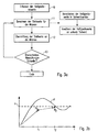
- step 13 a check can take place, in which case the brightness actual values are again detected and compared with the desired values. If it turns out that the deviations exceed a certain threshold or limit, the steps 11 and 12 can be repeated, ie at the time t 2 corrected control values are transmitted to the lights, so that now the brightness value H 2 results. If, during the subsequent check 13, it is determined that the brightness actual values now match the setpoints sufficiently well, the method is ended.
- the calculation of the control values in step 11 is preferably carried out by using an iterative optimization algorithm. It is provided in particular that the behavior of the system is predicted by a simulation calculation after each iteration step. Only when the system has settled in this mathematical simulation, the control values are transferred to the lights. This procedure leads very effectively to the desired results. When carrying out the simulation calculation, it is possible in particular to resort to earlier findings of the behavior of the system. These findings or information can be obtained, for example, in the context of an initialization of the system. The control unit controls the various lights at different control values and records and analyzes the resulting changes in the lighting in the various areas. Furthermore, the findings in the context of the review step 13 can also be taken into account.
- the simulation model can be suitably adapted in order to obtain better results when the method is carried out at a later time. In this way, a self-learning system is virtually formed, which is suitable for effectively calculating the required control values.
- a development of the method, in particular the calculation step 11 is schematically in FIG. 4 shown.
- the calculation of the manipulated variables is subdivided into temporally two consecutive phases.
- a calculation of the control values takes place in such a way that the calculated brightness values proceed from the actual state (represented by x) to a first calculated value. Care is taken that this first calculated value (represented by o) is within a setpoint corridor defined by an upper setpoint S o and a lower setpoint S u .
- the manipulated variables are calculated in such a way that all predicted brightness values lie between the two setpoints. In this way, it should first be ensured that the light quality, ie the lighting achieved, corresponds to the requirements defined by the setpoints.
- control values are then further optimized so that the final calculated or predicted brightness values (represented by annäh) approximate to the lower setpoint value, in particular come as close as possible to this setpoint value. This ultimately means that the individual brightness values are reduced as much as possible within the allowable range, which ultimately results in reduced energy consumption. Also in this case, of course, a transmission of the control values to the lights is made only after completion of the second phase.
- control values for anti-glare devices in particular the blind located on the window 101, could also be determined in this context.
- the influence of this blind can also be taken into account in the simulation calculation.
- FIG. 5 a particularly preferred embodiment of a light control system is shown schematically, which is used to carry out the method.
- the peculiarity consists in particular in the design of the sensor 120, which is able to detect the brightness actual values of several areas.
- the sensor 120 has an imaging digital sensor 10 with an associated optical system 11. That is, the sensor 120 ideally captures an image of the entire space (which, for example, is shown in FIG. 2 corresponds) and analyzes the corresponding image data to obtain the desired actual values.
- the digital image data can in this case first be processed by a further unit 12 in a suitable manner. Subsequently, an image data processing unit 13 then analyzes those data which are assigned to the areas A, B and C to be evaluated.
- a single sensor unit 120 can be used to obtain the required information regarding the current state of the system.
- This control information is then transmitted to the control unit 110, which calculates in the manner described above based on these data set values for the lights and blinds or generally for the actuators and transmitted to this.
- the setpoint values for the individual regions can be predetermined, for example, by manual input devices 111, which are likewise connected to the control unit 110.
- individual sensors instead of the multifunctional sensor unit described above. The operation of the control unit would not be affected thereby, as it is irrelevant for them, whether the control information or the actual values for the brightnesses in the individual areas are supplied by a single unit or multiple sensors.
Abstract
Description
Die vorliegende Erfindung betrifft ein Verfahren zur Lichtsteuerung, bei dem mehrere Leuchten angesteuert werden sollen, um in mehreren zu beleuchtenden Bereichen vorgegebene Helligkeitswerte zu erzielen. Ferner betrifft die vorliegende Erfindung ein entsprechendes System zur Durchführung des erfindungsgemäßen Verfahrens.The present invention relates to a method for light control, in which a plurality of luminaires are to be controlled in order to achieve predetermined brightness values in a plurality of areas to be illuminated. Furthermore, the present invention relates to a corresponding system for carrying out the method according to the invention.
Die Anforderungen an Beleuchtungseinrichtungen zur Beleuchtung von Räumen oder dergleichen werden immer umfangreicher. Während es in der Vergangenheit ausreichend war, einen Raum mit ausreichender Helligkeit auszuleuchten, besteht nunmehr oftmals das Bedürfnis, einzelne Bereiche des Raums individuell zu beleuchten. Beispielsweise kann gewünscht sein, einen Arbeitsbereich eines Raums mit einer verhältnismäßig hohen Helligkeit zu beleuchten, um hier optimale Arbeitsbedingungen zu schaffen. Ein anderer Bereich wiederum sollte weniger stark ausgeleuchtet werden. Ferner kann gewünscht sein, dass einzelne Objekte, die sich in dem Raum bzw. an dessen Wänden befinden, gezielt ausgeleuchtet werden.The requirements for lighting equipment for lighting rooms or the like are becoming more extensive. While it has been sufficient in the past to illuminate a room with sufficient brightness, there is now often the need to individually illuminate individual areas of the room. For example, it may be desirable to illuminate a working area of a room having a relatively high brightness to provide optimum working conditions. Another area, in turn, should be less illuminated. Furthermore, it may be desired that individual objects that are located in the room or on its walls are specifically illuminated.
Zum Erfüllen dieser verschiedenen Aufgaben stehen in der Regel mehrere Leuchten zur Verfügung, welche in geeigneter Weise angesteuert werden und insbesondere in ihrer Lichtabgabe beeinflusst werden können. Sollen nunmehr mit einer bestimmten Anzahl von Leuchten mehrere der oben genannten Aufgaben erfüllt werden, so ist zu berücksichtigen, dass die verschiedenen Bereiche, in denen eine gewünschte Helligkeit erzielt werden soll, nicht isoliert betrachtet werden können. Oftmals sind diese Bereiche benachbart oder weisen sogar eine geringfügige Überlappung auf, was zur Folge hat, dass die Beleuchtung eines Bereichs oder Objekts zwangsläufig auch Auswirkungen auf die Beleuchtung des anderen Bereichs hat. Dementsprechend müssen geeignete Stellwerte für die Leuchten gefunden werden, mit denen alle Aufgaben gleichzeitig möglichst gut erfüllt werden können.To fulfill these various tasks are usually several lights available, which are controlled in a suitable manner and can be influenced in particular in their light output. If now several of the above-mentioned tasks are to be fulfilled with a certain number of luminaires, it must be considered that the various areas in which a desired brightness is to be achieved can not be considered in isolation. Often, these areas are adjacent or even slightly overlapped, with the result that the illumination of one area or object will inevitably affect the lighting of the other area. Accordingly, suitable control values for the luminaires must be found, with which all tasks can be fulfilled as well as possible at the same time.
Die übliche Vorgehensweise hierzu wäre, eine entsprechende Regelung durchzuführen. Die Istwerte der Beleuchtung in den verschiedenen Bereichen werden hierbei erfasst und dann an eine Steuereinheit übermittelt, welche wiederum Änderungen an den Stellwerten für die Leuchten vornimmt, um Abweichungen von den gewünschten Helligkeits-Sollwerten zu reduzieren. Prinzipiell kann mit einer derartigen Vorgehensweise letztendlich das gewünschte Ergebnis erzielt werden. Es ergibt sich allerdings das Problem, dass im Falle einer derartigen Regelung vor Erreichen des Endzustands starke Schwankungen auftreten können. Dieses sogenannte Einschwingverhalten, welches vorübergehend zu periodischen Veränderungen der Helligkeiten führt, wird als unangenehm empfunden und sollte dementsprechend vermieden werden.The usual procedure would be to implement a corresponding regulation. The actual values of the lighting in the various areas are detected here and then transmitted to a control unit, which in turn makes changes to the control values for the lights to reduce deviations from the desired brightness setpoints. In principle, the desired result can ultimately be achieved with such a procedure. It However, there is the problem that in the case of such a regulation before reaching the final state, large fluctuations may occur. This so-called transient behavior, which temporarily leads to periodic changes in the brightness, is perceived as unpleasant and should accordingly be avoided.
Dementsprechend liegt der vorliegenden Erfindung die Aufgabe zugrunde, eine neuartige Möglichkeit zur Lichtsteuerung anzugeben, welche das oben genannte Problem löst, gleichzeitig allerdings das Auftreten von Helligkeitsschwankungen möglichst unterdrückt.Accordingly, the present invention has for its object to provide a novel possibility for light control, which solves the above problem, while suppressing the occurrence of brightness variations as possible.
Die Aufgabe wird durch ein Verfahren zur Lichtsteuerung mit den Merkmalen des Anspruchs 1 sowie durch ein Lichtsteuersystem gemäß Anspruch 8 gelöst. Vorteilhafte Weiterbildungen der Erfindung sind Gegenstand der abhängigen Ansprüche.The object is achieved by a method for light control with the features of claim 1 and by a light control system according to claim 8. Advantageous developments of the invention are the subject of the dependent claims.
Die erfindungsgemäße Lösung beruht auf dem Gedanken, keine klassische Regelung der Helligkeiten vorzunehmen. Stattdessen werden geeignete Stellwerte für die Leuchte rechnerisch ermittelt und erst nach Abschluss der Berechnungen an die Leuchten übermittelt. Wie nachfolgend näher erläutert wird, kann hierdurch das als unangenehm empfundene Einschwingverhalten vermieden werden.The solution according to the invention is based on the idea of not making a classical regulation of the brightnesses. Instead, suitable control values for the luminaire are calculated and transmitted to the luminaires only after the calculations have been completed. As will be explained in more detail below, this can be avoided as the unpleasant transient response.
Erfindungsgemäß wird dementsprechend ein Lichtsteuerverfahren zum Ansteuern mehrerer Leuchten vorgeschlagen, wobei das Verfahren dazu vorgesehen ist, in mehreren Bereichen vorgegebene Helligkeitswerte zu erzielen. Das Verfahren weist dabei folgende Schritte auf:
- a) Ermitteln der Helligkeits-Istwerte in den zu beleuchtenden Bereichen,
- b) Berechnen von Stellwerten für die Leuchten derart, dass die Gesamtheit der Abweichungen der berechneten Helligkeitswerte von den Sollwerten ein Minimum erreicht, und
- c) Übermitteln der Stellwerte an die Leuchten.
- a) determining the brightness actual values in the areas to be illuminated,
- b) calculating set values for the luminaires such that the totality of the deviations of the calculated brightness values from the set values reaches a minimum, and
- c) transmission of the control values to the luminaires.
Die zuvor genannten Schritte b) und c) können dabei wiederholt werden, falls die Abweichungen der sich tatsächlich ergebenden Helligkeitswerte von den Sollwerten eine bestimmte Schwelle oder Grenze überschreiten.The aforementioned steps b) and c) can be repeated if the deviations of the actually resulting brightness values from the desired values exceed a certain threshold or limit.
Das Berechnen der Stellwerte in dem oben genannten Schritt b) erfolgt vorzugsweise in zwei Teilschritten, wobei in einem ersten Teilschritt die Stellwerte derart berechnet werden, dass die berechneten bzw. theoretischen Helligkeitswerte jeweils zwischen einem oberen und einem unteren Sollwert liegen. In einem zweiten Teilschritt werden dann die Stellwerte derart modifiziert, dass sich die berechneten Helligkeitswerte jeweils möglichst gut den unteren Sollwerten annähern. Im ersten Schritt wird also darauf geachtet, dass die Anforderungen an die Beleuchtung insgesamt erfüllt werden. Mit dem zweiten Schritt der Annäherung an die unteren Sollwerte wird eine energetische Optimierung erreicht, d.h. der Stromverbrauch insgesamt wird reduziert.The calculation of the manipulated variables in the abovementioned step b) is preferably carried out in two sub-steps, wherein in a first sub-step the manipulated values are calculated in such a way that the calculated or theoretical brightness values respectively lie between an upper and a lower desired value. In a second step then the manipulated variables are modified in such a way that the calculated brightness values approach each other as well as possible to the lower setpoint values. In the first step, care is taken to ensure that the lighting requirements are met as a whole. With the second step of approaching the lower setpoints, an energetic optimization is achieved, ie the total power consumption is reduced.
Das Berechnen der Stellwerte erfolgt vorzugsweise im Rahmen eines Iterationsverfahrens, wobei die Stellwerte an die Leuchten erst nach Abschluss des Iterationsverfahrens übermittelt werden. Die einzelnen Iterationsschritte werden dabei auf Basis einer Simulationsberechnung des Systems durchgeführt, wobei hierzu beispielsweise auf Daten zurückgegriffen werden kann, welche in einem Initialisierungsprozess des Systems erhalten wurden. Diese Informationen können allerdings während des weiteren Betriebs des Systems jederzeit aktualisiert werden. Sollte sich beispielsweise herausstellen, dass nach Übermittlung der Stellwerte an die Leuchten Abweichungen von den Sollwerten vorliegen, so können diese bei der Simulation des Systems zu einem späteren Zeitpunkt berücksichtigt werden. Hierdurch wird das Verfahren in einem selbstlernenden Prozess fortgehend optimiert. Auch Veränderungen in der Lichtabgabe der Leuchten, die auf thermische Schwankungen, insbesondere jedoch auf Alterserscheinungen zurückzuführen sind, können auf diesem Wege berücksichtigt und ausgeglichen werden.The control values are preferably calculated in the context of an iteration method, wherein the control values are transmitted to the luminaires only after completion of the iteration process. The individual iteration steps are carried out on the basis of a simulation calculation of the system, for which purpose it is possible, for example, to resort to data obtained in an initialization process of the system. However, this information may be updated at any time as the system continues to operate. If, for example, it should turn out that there are deviations from the setpoints after the control values have been transmitted to the luminaires, these can be taken into account when simulating the system at a later time. As a result, the process is further optimized in a self-learning process. Also, changes in the light output of the lights, which are due to thermal fluctuations, but especially due to aging, can be considered and compensated in this way.
Letztendlich können mit dem erfindungsgemäßen Verfahren geeignete Stellwerte für die Leuchte in schneller und zuverlässiger Weise ermittelt werden, ohne dass beim Ansteuern der Leuchten unerwünschte Lichtschwankungen auftreten.Finally, with the method according to the invention, suitable setting values for the luminaire can be determined in a fast and reliable manner without unwanted light fluctuations occurring when the luminaires are activated.
Nachfolgend soll die Erfindung anhand der beiliegenden Zeichnung näher erläutert werden. Es zeigen:
- Figuren 1 und 2
- Ansichten eines zu beleuchtenden Raums zur Verdeutlichung des der Erfindung zugrunde liegenden Problems;
- Figur 3a
- schematisch den Ablauf des erfindungsgemäßen Verfahrens;
- Figur 3b
- den Vergleich der erfindungsgemäßen Vorgehensweise zu einem klassischen Regelungsverfahren;
- Figur 4
- ein Schema zur Verdeutlichung der Vorgehensweise beim zweistufigen Berechnen der Stellwerte und
- Figur 5
- die Komponenten eines zur Durchführung des erfindungsgemäßen Verfahrens geeigneten Lichtsteuersystems.
- Figures 1 and 2
- Views of a room to be illuminated to illustrate the problem underlying the invention;
- FIG. 3a
- schematically the course of the method according to the invention;
- FIG. 3b
- the comparison of the procedure according to the invention to a classic control method;
- FIG. 4
- a scheme to illustrate the procedure for the two-stage calculation of the control values and
- FIG. 5
- the components of a suitable for carrying out the method according to the invention light control system.
Anhand der
Verschiedene Bereiche des Raums 100 sollen nun mit Hilfe der Leuchten 107 bis 109 in unterschiedlicher Weise ausgeleuchtet werden. So ist beispielsweise gewünscht, einen ersten Bereich A, der die Arbeitsfläche 106 des Tisches 105 bildet, mit sehr hoher Helligkeit auszuleuchten, um hier optimale Arbeitsbedingungen zu schaffen. Ein zweiter Bereich B hingegen, der sich in der Nähe einer Eingangstür 102 befindet, sollte mit einer niedrigeren Helligkeit ausgeleuchtet werden. Schließlich ist es gewünscht, einen Bereich C an der Wand gezielt mit einer sehr hohen Helligkeit auszuleuchten, um beispielsweise ein in diesem Bereich der Wand angeordnetes Objekt zu beleuchten.Different areas of the
Drei verschiedene Bereiche A, B und C des Raums 100 sollen also mit Hilfe der drei Leuchten 107 bis 109 in unterschiedlicher Weise ausgeleuchtet werden. Hierfür müssen geeignete Stellwerte für die Leuchten 107 bis 109 gefunden werden, um diese Problemstellung zu lösen. Bereits an dieser Stelle sei darauf hingewiesen, dass die vorliegende Erfindung nicht auf solche Systeme beschränkt ist, bei denen die Anzahl der verschiedenen zu beleuchtenden Bereiche genau der Anzahl der Leuchten entspricht. Die Anzahl m der verschiedenen Flächen bzw. Bereiche kann durchaus auch von der Anzahl n der Leuchten abweisen, wobei die Anzahl der Leuchten sowohl größer als auch kleiner der Anzahl der zu beleuchtenden Bereiche sein kann.Three different areas A, B and C of the
Ein entsprechendes Einstellen der Leuchten 107 bis 109 in sinnvoller Weise ist nur dann möglich, wenn Informationen über den aktuellen Zustand der Beleuchtung in den verschiedenen Bereichen erhalten werden. Hierfür ist an der Decke des Raums ein nachfolgend noch näher beschriebener Sensor 120 angeordnet, der geeignete Kontrollinformationen erstellt. Insbesondere erfasst der Sensor 120 die Helligkeits-Istwerte in den drei Bereichen A, B, C. Diese werden an eine Steuereinheit 110 übermittelt, welche dann eine geeignete Ansteuerung der Leuchten 107 bis 109 vornimmt.An appropriate setting of the
In Kenntnis der Helligkeits-Istwerte für die drei Bereiche wäre es möglich, die Stellwerte für die Leuchten 107 bis 109 im Rahmen einer Regelung kontinuierlich zu verändern und die sich hierbei ergebenden Änderungen der Helligkeits-Istwerte zu erfassen. Diese Anpassung der Stellwerte wird so lange durchgeführt, bis letztendlich die Bereiche in der gewünschten Weise beleuchtet werden.With knowledge of the brightness actual values for the three ranges, it would be possible to continuously change the manipulated values for the
Bei dieser dem Stand der Technik entsprechenden Vorgehensweise ergibt sich allerdings dann üblicherweise ein zeitliches Verhalten des Systems, welches in
Das schematisch in
In
Aufgrund von äußeren Einflüssen und/oder Alterungserscheinungen der Leuchten oder Lichtquellen kann allerdings nicht ausgeschlossen werden, dass noch eine Abweichung der letztendlich erzielten Helligkeitswerte von den Sollwerten vorliegt. In dem nachfolgenden Schritt 13 kann dementsprechend eine Überprüfung stattfinden, wobei wiederum die Helligkeits-Istwerte erfasst und mit den Sollwerten verglichen werden. Stellt sich heraus, dass die Abweichungen eine gewisse Schwelle oder Grenze überschreiten, können die Schritte 11 und 12 wiederholt werden, d.h. zum Zeitpunkt t2 werden korrigierte Stellwerte an die Leuchten übermittelt, sodass sich nunmehr der Helligkeitswert H2 ergibt. Wird bei der nachfolgenden Überprüfung 13 festgestellt, dass nunmehr die Helligkeits-Istwerte hinreichend gut mit den Sollwerten übereinstimmen, wird das Verfahren beendet.However, due to external influences and / or aging phenomena of the luminaires or light sources, it can not be ruled out that there is still a deviation of the finally achieved brightness values from the desired values. Accordingly, in the following
Die zuvor erwähnte Schleife könnte im Prinzip mehrfach durchlaufen werden, allerdings dürften bereits nach ein oder zwei Durchgängen die Abweichungen derart gering sein, dass keine weitere Anpassung erforderlich ist. Ein Vergleich zu Kurve II zeigt unmittelbar, dass bei der Durchführung des Verfahrens kein Einschwingverhalten vorliegt, sondern stattdessen in wenigen Schritten die Helligkeiten auf die gewünschten Werte eingestellt werden.The previously mentioned loop could in principle be run through several times, but after only one or two passes the deviations should be so small that no further adaptation is required. A comparison to curve II shows directly that there is no transient response in the implementation of the method, but instead the brightnesses are set to the desired values in a few steps.
Das Berechnen der Stellwerte in Schritt 11 erfolgt vorzugsweise durch Verwendung eines iterativen Optimierungsalgorithmus. Dabei ist insbesondere vorgesehen, dass das Verhalten des Systems durch eine Simulationsrechnung nach jedem Iterationsschritt prognostiziert wird. Erst wenn das System in dieser rechnerischen Simulation eingeschwungen ist, werden die Stellwerte an die Leuchten übergeben. Diese Vorgehensweise führt sehr effektiv zu den gewünschten Ergebnissen. Bei der Durchführung der Simulationsrechnung kann dabei insbesondere auf frühere Erkenntnisse des Verhaltens des Systems zurückgegriffen werden. Diese Erkenntnisse bzw. Informationen können beispielsweise im Rahmen einer Initialisierung des Systems gewonnen werden. Dabei werden durch die Steuereinheit die verschiedenen Leuchten bei verschiedenen Stellwerten angesteuert und die sich hierbei ergebenden Veränderungen der Beleuchtung in den verschiedenen Bereichen erfasst und analysiert. Ferner können hierbei auch die Erkenntnisse im Rahmen des Überprüfungsschritts 13 berücksichtigt werden. Wird beispielsweise festgestellt, dass bei Durchführung der Simulation grundsätzlich in einem Bereich die Helligkeit zu niedrig ist, so kann das Simulationsmodell in geeigneter Weise angepasst werden, um bei einer Durchführung des Verfahrens zu einem späteren Zeitpunkt bessere Ergebnisse zu erhalten. Auf diesem Wege wird quasi ein selbstlernendes System gebildet, welches zum effektiven Berechnen der erforderlichen Stellwerte geeignet ist.The calculation of the control values in
Eine Weiterbildung des Verfahrens, insbesondere des Berechnungsschritts 11 ist schematisch in
In einem zweiten Schritt, dargestellt durch die gestrichelten Pfeile, werden dann die Stellwerte weiter dahingehend optimiert, dass sich die endgültigen berechneten bzw. prognostizierten Helligkeitswerte (dargestellt durch •) an den unteren Sollwert annähern, insbesondere möglichst nah an diesen Sollwert kommen. Dies bedeutet letztendlich, dass die einzelnen Helligkeitswerte soweit wie möglich innerhalb des zulässigen Bereichs reduziert werden, was letztendlich einen reduzierten Energieverbrauch nach sich zieht. Auch in diesem Fall wird selbstverständlich erst nach Beendigung der zweiten Phase eine Übermittlung der Stellwerte an die Leuchten vorgenommen.In a second step, represented by the dashed arrows, the control values are then further optimized so that the final calculated or predicted brightness values (represented by annäh) approximate to the lower setpoint value, in particular come as close as possible to this setpoint value. This ultimately means that the individual brightness values are reduced as much as possible within the allowable range, which ultimately results in reduced energy consumption. Also in this case, of course, a transmission of the control values to the lights is made only after completion of the second phase.
Anzumerken ist, dass das Verfahren nicht auf die ausschließliche Ansteuerung von Leuchten beschränkt ist. Beispielsweise könnten in diesem Zusammenhang auch Stellwerte für Blendschutzeinrichtungen, insbesondere die an dem Fenster 101 befindliche Jalousie ermittelt werden. Auch der Einfluss dieser Jalousie kann im Rahmen der Simulationsrechnung berücksichtigt werden.It should be noted that the method is not limited to the exclusive control of luminaires. For example, control values for anti-glare devices, in particular the blind located on the
In
Anstelle einer Vielzahl einzelner Sensoren, welche jeweils auf die Bereiche A, B und C gerichtet sind, kann also lediglich eine einzelne Sensoreinheit 120 verwenden werden, um die erforderlichen Informationen hinsichtlich des Istzustands des Systems zu erhalten. Diese Kontrollinformationen werden dann an die Steuereinheit 110 übermittelt, welche in der oben beschriebenen Weise auf Basis dieser Daten Stellwerte für die Leuchten und Jalousien bzw. allgemein für die Aktoren berechnet und an diese übermittelt. Die Sollwerte für die einzelnen Bereiche können beispielsweise durch manuelle Eingabegeräte 111 vorgegeben werden, welche ebenfalls mit der Steuereinheit 110 verbunden sind. Selbstverständlich wäre es auch möglich, anstelle der zuvor beschriebenen multifunktionalen Sensoreinheit jeweils einzelne Sensoren einzusetzen. Die Funktionsweise der Steuereinheit würde hierdurch nicht beeinflusst werden, da es für diese unerheblich ist, ob die Kontrollinformationen bzw. die Istwerte für die Helligkeiten in den einzelnen Bereichen von einer einzigen Einheit oder mehreren Sensoren geliefert werden.Instead of a plurality of individual sensors, which are respectively directed to the areas A, B and C, so only a
Claims (8)
dadurch gekennzeichnet,
dass die Schritte b) und c) wiederholt werden, wenn die Abweichung der sich tatsächlich ergebenden Helligkeitswerte von den Sollwerten eine Schwelle überschreitet.Light control method according to claim 1,
characterized,
that steps b) and c) are repeated if the deviation of the actually resulting brightness values from the desired values exceeds a threshold.
dadurch gekennzeichnet,
dass das Berechnen der Stellwerte in Schritt b) in zwei Teilschritten erfolgt, wobei
characterized,
that the calculation of the control values in step b) takes place in two substeps, wherein
dadurch gekennzeichnet,
dass die Berechnung der Stellwerte im Rahmen eines Iterationsverfahrens erfolgt, wobei die Stellwerte an die Leuchten (107, 108, 109) erst nach Abschluss des Iterationsverfahrens übermittelt werden.Method according to one of the preceding claims,
characterized,
in that the calculation of the control values takes place within the framework of an iterative process, wherein the control values are transmitted to the luminaires (107, 108, 109) only after completion of the iteration process.
dadurch gekennzeichnet,
dass die einzelnen Iterationsschritte im Rahmen einer Simulationsberechnung des Systems erfolgen.Method according to claim 4,
characterized,
that the individual iteration steps take place within the framework of a simulation calculation of the system.
dadurch gekennzeichnet,
dass der Simulationsberechnung in einem Initialisierungsprozeß erfasste Daten zugrunde gelegt werden.Method according to claim 5,
characterized,
that the simulation calculation is based on data acquired in an initialization process.
dadurch gekennzeichnet,
dass nach Übermittlung der Stellwerte an die Leuchten (107, 108, 109) vorliegende Abweichungen von den Sollwerten erfaßt und bei der Simulationsberechnung berücksichtigt werden.Method according to claim 5 or 6,
characterized,
that after transmission of the manipulated variables to the luminaires (107, 108, 109) deviations from the desired values are recorded and taken into account in the simulation calculation.
Applications Claiming Priority (1)
| Application Number | Priority Date | Filing Date | Title |
|---|---|---|---|
| DE102010003803A DE102010003803A1 (en) | 2010-04-09 | 2010-04-09 | Method for lighting control and lighting control system |
Publications (3)
| Publication Number | Publication Date |
|---|---|
| EP2375871A2 true EP2375871A2 (en) | 2011-10-12 |
| EP2375871A3 EP2375871A3 (en) | 2016-08-31 |
| EP2375871B1 EP2375871B1 (en) | 2017-09-13 |
Family
ID=44343748
Family Applications (1)
| Application Number | Title | Priority Date | Filing Date |
|---|---|---|---|
| EP11161523.3A Active EP2375871B1 (en) | 2010-04-09 | 2011-04-07 | Light control method and system |
Country Status (2)
| Country | Link |
|---|---|
| EP (1) | EP2375871B1 (en) |
| DE (1) | DE102010003803A1 (en) |
Cited By (2)
| Publication number | Priority date | Publication date | Assignee | Title |
|---|---|---|---|---|
| CN106982505A (en) * | 2017-05-19 | 2017-07-25 | 北京同步科技有限公司 | The intelligent open loop debugging system and its adjustment method of light |
| AT518823A1 (en) * | 2016-07-04 | 2018-01-15 | Bernecker + Rainer Industrie-Elektronik Ges M B H | Illumination arrangement for industrial image processing |
Citations (2)
| Publication number | Priority date | Publication date | Assignee | Title |
|---|---|---|---|---|
| EP0652690A1 (en) * | 1993-11-09 | 1995-05-10 | Laboratoires D'electronique Philips S.A.S. | Automatic control device for lighting |
| WO2008001259A2 (en) * | 2006-06-28 | 2008-01-03 | Philips Intellectual Property & Standards Gmbh | Method of controlling a lighting system based on a target light distribution |
Family Cites Families (3)
| Publication number | Priority date | Publication date | Assignee | Title |
|---|---|---|---|---|
| DE19619281A1 (en) * | 1996-05-13 | 1997-11-20 | Zumtobel Licht | System and control device for controlling the brightness of a room |
| DE19842465A1 (en) * | 1998-09-16 | 2000-03-23 | Siemens Ag | Constant light control method |
| DE102004047962A1 (en) * | 2004-10-01 | 2006-04-06 | Patent-Treuhand-Gesellschaft für elektrische Glühlampen mbH | sensor system |
-
2010
- 2010-04-09 DE DE102010003803A patent/DE102010003803A1/en not_active Withdrawn
-
2011
- 2011-04-07 EP EP11161523.3A patent/EP2375871B1/en active Active
Patent Citations (2)
| Publication number | Priority date | Publication date | Assignee | Title |
|---|---|---|---|---|
| EP0652690A1 (en) * | 1993-11-09 | 1995-05-10 | Laboratoires D'electronique Philips S.A.S. | Automatic control device for lighting |
| WO2008001259A2 (en) * | 2006-06-28 | 2008-01-03 | Philips Intellectual Property & Standards Gmbh | Method of controlling a lighting system based on a target light distribution |
Cited By (3)
| Publication number | Priority date | Publication date | Assignee | Title |
|---|---|---|---|---|
| AT518823A1 (en) * | 2016-07-04 | 2018-01-15 | Bernecker + Rainer Industrie-Elektronik Ges M B H | Illumination arrangement for industrial image processing |
| US10390412B2 (en) | 2016-07-04 | 2019-08-20 | B&R Industrial Automation GmbH | Lighting arrangement for industrial image processing |
| CN106982505A (en) * | 2017-05-19 | 2017-07-25 | 北京同步科技有限公司 | The intelligent open loop debugging system and its adjustment method of light |
Also Published As
| Publication number | Publication date |
|---|---|
| DE102010003803A1 (en) | 2011-10-13 |
| EP2375871B1 (en) | 2017-09-13 |
| EP2375871A3 (en) | 2016-08-31 |
Similar Documents
| Publication | Publication Date | Title |
|---|---|---|
| EP2560464B1 (en) | Method for controlling and regulating a light system | |
| DE19619281A1 (en) | System and control device for controlling the brightness of a room | |
| EP2835037B1 (en) | Method and device for regulating an illuminance using an adaptive control loop factor | |
| DE102010003804A1 (en) | Multifunctional sensor unit for determining control information for the light control | |
| EP3142464B1 (en) | Lighting system | |
| EP2375871B1 (en) | Light control method and system | |
| EP3251469B1 (en) | Method for operating devices in a lighting system | |
| EP2202596B1 (en) | Assembly consisting of a programmable unit and a power block connected thereto | |
| EP2288969B1 (en) | Control system of a plant having multi-stage model optimization | |
| DE102013212789A1 (en) | Lighting system and luminaire with emergency light function | |
| EP2732541B1 (en) | Assembly having a potential-isolated electrical power supply device | |
| EP2475227B1 (en) | Lighting system with multiple lights and device for implementing positioning values | |
| DE102012210959A1 (en) | Distributed consumer control system and system commissioning process | |
| EP2375870B1 (en) | Light control method and system | |
| DE4343017A1 (en) | Method for adjusting the total light in a room and device for carrying out the method | |
| EP3217765A1 (en) | Simplified commissioning concept for controlling actuators of an installation in a building | |
| EP2984904B1 (en) | Method for controlling a lamp having a plurality of sub-units | |
| DE3221873C2 (en) | Method and arrangement for reducing the energy consumption of a stage control system | |
| DE102015216362A1 (en) | Communicating headlights of several vehicles | |
| WO2016050599A1 (en) | Method for determining the energy requirement of a production machine or of a production system comprising a plurality of production machines, and measuring device suitable for performing the method | |
| WO2021058502A1 (en) | Controlling a robot manipulator | |
| DE4216699A1 (en) | Automatic computer-controlled protection of plant esp. of nuclear power station - uses computer network for redundant collection and processing of plant input signals and for delivery output signals e.g. adjustment commands to systems | |
| AT16014U1 (en) | Operating device for operating light bulbs | |
| EP3138369B1 (en) | Method for operating a light having a plurality of lighting units which are arranged behind each other | |
| DE102022122754A1 (en) | SYSTEMS AND METHODS FOR MONITORING THE CONDITION OF A CHAIN |
Legal Events
| Date | Code | Title | Description |
|---|---|---|---|
| PUAI | Public reference made under article 153(3) epc to a published international application that has entered the european phase |
Free format text: ORIGINAL CODE: 0009012 |
|
| AK | Designated contracting states |
Kind code of ref document: A2 Designated state(s): AL AT BE BG CH CY CZ DE DK EE ES FI FR GB GR HR HU IE IS IT LI LT LU LV MC MK MT NL NO PL PT RO RS SE SI SK SM TR |
|
| AX | Request for extension of the european patent |
Extension state: BA ME |
|
| PUAL | Search report despatched |
Free format text: ORIGINAL CODE: 0009013 |
|
| AK | Designated contracting states |
Kind code of ref document: A3 Designated state(s): AL AT BE BG CH CY CZ DE DK EE ES FI FR GB GR HR HU IE IS IT LI LT LU LV MC MK MT NL NO PL PT RO RS SE SI SK SM TR |
|
| AX | Request for extension of the european patent |
Extension state: BA ME |
|
| RIC1 | Information provided on ipc code assigned before grant |
Ipc: H05B 37/02 20060101AFI20160722BHEP |
|
| STAA | Information on the status of an ep patent application or granted ep patent |
Free format text: STATUS: REQUEST FOR EXAMINATION WAS MADE |
|
| 17P | Request for examination filed |
Effective date: 20170221 |
|
| RBV | Designated contracting states (corrected) |
Designated state(s): AL AT BE BG CH CY CZ DE DK EE ES FI FR GB GR HR HU IE IS IT LI LT LU LV MC MK MT NL NO PL PT RO RS SE SI SK SM TR |
|
| GRAP | Despatch of communication of intention to grant a patent |
Free format text: ORIGINAL CODE: EPIDOSNIGR1 |
|
| STAA | Information on the status of an ep patent application or granted ep patent |
Free format text: STATUS: GRANT OF PATENT IS INTENDED |
|
| INTG | Intention to grant announced |
Effective date: 20170418 |
|
| GRAS | Grant fee paid |
Free format text: ORIGINAL CODE: EPIDOSNIGR3 |
|
| GRAA | (expected) grant |
Free format text: ORIGINAL CODE: 0009210 |
|
| STAA | Information on the status of an ep patent application or granted ep patent |
Free format text: STATUS: THE PATENT HAS BEEN GRANTED |
|
| AK | Designated contracting states |
Kind code of ref document: B1 Designated state(s): AL AT BE BG CH CY CZ DE DK EE ES FI FR GB GR HR HU IE IS IT LI LT LU LV MC MK MT NL NO PL PT RO RS SE SI SK SM TR |
|
| REG | Reference to a national code |
Ref country code: GB Ref legal event code: FG4D Free format text: NOT ENGLISH |
|
| REG | Reference to a national code |
Ref country code: CH Ref legal event code: EP Ref country code: CH Ref legal event code: NV Representative=s name: FELBER UND PARTNER AG, CH |
|
| REG | Reference to a national code |
Ref country code: IE Ref legal event code: FG4D Free format text: LANGUAGE OF EP DOCUMENT: GERMAN |
|
| REG | Reference to a national code |
Ref country code: AT Ref legal event code: REF Ref document number: 929394 Country of ref document: AT Kind code of ref document: T Effective date: 20171015 |
|
| REG | Reference to a national code |
Ref country code: DE Ref legal event code: R096 Ref document number: 502011012978 Country of ref document: DE |
|
| REG | Reference to a national code |
Ref country code: NL Ref legal event code: MP Effective date: 20170913 |
|
| REG | Reference to a national code |
Ref country code: LT Ref legal event code: MG4D |
|
| PG25 | Lapsed in a contracting state [announced via postgrant information from national office to epo] |
Ref country code: FI Free format text: LAPSE BECAUSE OF FAILURE TO SUBMIT A TRANSLATION OF THE DESCRIPTION OR TO PAY THE FEE WITHIN THE PRESCRIBED TIME-LIMIT Effective date: 20170913 Ref country code: LT Free format text: LAPSE BECAUSE OF FAILURE TO SUBMIT A TRANSLATION OF THE DESCRIPTION OR TO PAY THE FEE WITHIN THE PRESCRIBED TIME-LIMIT Effective date: 20170913 Ref country code: SE Free format text: LAPSE BECAUSE OF FAILURE TO SUBMIT A TRANSLATION OF THE DESCRIPTION OR TO PAY THE FEE WITHIN THE PRESCRIBED TIME-LIMIT Effective date: 20170913 Ref country code: HR Free format text: LAPSE BECAUSE OF FAILURE TO SUBMIT A TRANSLATION OF THE DESCRIPTION OR TO PAY THE FEE WITHIN THE PRESCRIBED TIME-LIMIT Effective date: 20170913 Ref country code: NO Free format text: LAPSE BECAUSE OF FAILURE TO SUBMIT A TRANSLATION OF THE DESCRIPTION OR TO PAY THE FEE WITHIN THE PRESCRIBED TIME-LIMIT Effective date: 20171213 |
|
| PG25 | Lapsed in a contracting state [announced via postgrant information from national office to epo] |
Ref country code: ES Free format text: LAPSE BECAUSE OF FAILURE TO SUBMIT A TRANSLATION OF THE DESCRIPTION OR TO PAY THE FEE WITHIN THE PRESCRIBED TIME-LIMIT Effective date: 20170913 Ref country code: LV Free format text: LAPSE BECAUSE OF FAILURE TO SUBMIT A TRANSLATION OF THE DESCRIPTION OR TO PAY THE FEE WITHIN THE PRESCRIBED TIME-LIMIT Effective date: 20170913 Ref country code: RS Free format text: LAPSE BECAUSE OF FAILURE TO SUBMIT A TRANSLATION OF THE DESCRIPTION OR TO PAY THE FEE WITHIN THE PRESCRIBED TIME-LIMIT Effective date: 20170913 Ref country code: BG Free format text: LAPSE BECAUSE OF FAILURE TO SUBMIT A TRANSLATION OF THE DESCRIPTION OR TO PAY THE FEE WITHIN THE PRESCRIBED TIME-LIMIT Effective date: 20171213 Ref country code: GR Free format text: LAPSE BECAUSE OF FAILURE TO SUBMIT A TRANSLATION OF THE DESCRIPTION OR TO PAY THE FEE WITHIN THE PRESCRIBED TIME-LIMIT Effective date: 20171214 |
|
| PG25 | Lapsed in a contracting state [announced via postgrant information from national office to epo] |
Ref country code: NL Free format text: LAPSE BECAUSE OF FAILURE TO SUBMIT A TRANSLATION OF THE DESCRIPTION OR TO PAY THE FEE WITHIN THE PRESCRIBED TIME-LIMIT Effective date: 20170913 |
|
| REG | Reference to a national code |
Ref country code: FR Ref legal event code: PLFP Year of fee payment: 8 |
|
| PG25 | Lapsed in a contracting state [announced via postgrant information from national office to epo] |
Ref country code: CZ Free format text: LAPSE BECAUSE OF FAILURE TO SUBMIT A TRANSLATION OF THE DESCRIPTION OR TO PAY THE FEE WITHIN THE PRESCRIBED TIME-LIMIT Effective date: 20170913 Ref country code: RO Free format text: LAPSE BECAUSE OF FAILURE TO SUBMIT A TRANSLATION OF THE DESCRIPTION OR TO PAY THE FEE WITHIN THE PRESCRIBED TIME-LIMIT Effective date: 20170913 Ref country code: PL Free format text: LAPSE BECAUSE OF FAILURE TO SUBMIT A TRANSLATION OF THE DESCRIPTION OR TO PAY THE FEE WITHIN THE PRESCRIBED TIME-LIMIT Effective date: 20170913 |
|
| PG25 | Lapsed in a contracting state [announced via postgrant information from national office to epo] |
Ref country code: EE Free format text: LAPSE BECAUSE OF FAILURE TO SUBMIT A TRANSLATION OF THE DESCRIPTION OR TO PAY THE FEE WITHIN THE PRESCRIBED TIME-LIMIT Effective date: 20170913 Ref country code: SK Free format text: LAPSE BECAUSE OF FAILURE TO SUBMIT A TRANSLATION OF THE DESCRIPTION OR TO PAY THE FEE WITHIN THE PRESCRIBED TIME-LIMIT Effective date: 20170913 Ref country code: IT Free format text: LAPSE BECAUSE OF FAILURE TO SUBMIT A TRANSLATION OF THE DESCRIPTION OR TO PAY THE FEE WITHIN THE PRESCRIBED TIME-LIMIT Effective date: 20170913 Ref country code: IS Free format text: LAPSE BECAUSE OF FAILURE TO SUBMIT A TRANSLATION OF THE DESCRIPTION OR TO PAY THE FEE WITHIN THE PRESCRIBED TIME-LIMIT Effective date: 20180113 Ref country code: SM Free format text: LAPSE BECAUSE OF FAILURE TO SUBMIT A TRANSLATION OF THE DESCRIPTION OR TO PAY THE FEE WITHIN THE PRESCRIBED TIME-LIMIT Effective date: 20170913 |
|
| REG | Reference to a national code |
Ref country code: DE Ref legal event code: R097 Ref document number: 502011012978 Country of ref document: DE |
|
| PLBE | No opposition filed within time limit |
Free format text: ORIGINAL CODE: 0009261 |
|
| STAA | Information on the status of an ep patent application or granted ep patent |
Free format text: STATUS: NO OPPOSITION FILED WITHIN TIME LIMIT |
|
| PG25 | Lapsed in a contracting state [announced via postgrant information from national office to epo] |
Ref country code: DK Free format text: LAPSE BECAUSE OF FAILURE TO SUBMIT A TRANSLATION OF THE DESCRIPTION OR TO PAY THE FEE WITHIN THE PRESCRIBED TIME-LIMIT Effective date: 20170913 |
|
| 26N | No opposition filed |
Effective date: 20180614 |
|
| PG25 | Lapsed in a contracting state [announced via postgrant information from national office to epo] |
Ref country code: MT Free format text: LAPSE BECAUSE OF FAILURE TO SUBMIT A TRANSLATION OF THE DESCRIPTION OR TO PAY THE FEE WITHIN THE PRESCRIBED TIME-LIMIT Effective date: 20170913 |
|
| PG25 | Lapsed in a contracting state [announced via postgrant information from national office to epo] |
Ref country code: SI Free format text: LAPSE BECAUSE OF FAILURE TO SUBMIT A TRANSLATION OF THE DESCRIPTION OR TO PAY THE FEE WITHIN THE PRESCRIBED TIME-LIMIT Effective date: 20170913 Ref country code: MC Free format text: LAPSE BECAUSE OF FAILURE TO SUBMIT A TRANSLATION OF THE DESCRIPTION OR TO PAY THE FEE WITHIN THE PRESCRIBED TIME-LIMIT Effective date: 20170913 |
|
| REG | Reference to a national code |
Ref country code: BE Ref legal event code: MM Effective date: 20180430 |
|
| REG | Reference to a national code |
Ref country code: IE Ref legal event code: MM4A |
|
| PG25 | Lapsed in a contracting state [announced via postgrant information from national office to epo] |
Ref country code: LU Free format text: LAPSE BECAUSE OF NON-PAYMENT OF DUE FEES Effective date: 20180407 |
|
| PG25 | Lapsed in a contracting state [announced via postgrant information from national office to epo] |
Ref country code: BE Free format text: LAPSE BECAUSE OF NON-PAYMENT OF DUE FEES Effective date: 20180430 |
|
| PG25 | Lapsed in a contracting state [announced via postgrant information from national office to epo] |
Ref country code: IE Free format text: LAPSE BECAUSE OF NON-PAYMENT OF DUE FEES Effective date: 20180407 |
|
| PGFP | Annual fee paid to national office [announced via postgrant information from national office to epo] |
Ref country code: AT Payment date: 20190425 Year of fee payment: 9 |
|
| PG25 | Lapsed in a contracting state [announced via postgrant information from national office to epo] |
Ref country code: TR Free format text: LAPSE BECAUSE OF FAILURE TO SUBMIT A TRANSLATION OF THE DESCRIPTION OR TO PAY THE FEE WITHIN THE PRESCRIBED TIME-LIMIT Effective date: 20170913 |
|
| PG25 | Lapsed in a contracting state [announced via postgrant information from national office to epo] |
Ref country code: HU Free format text: LAPSE BECAUSE OF FAILURE TO SUBMIT A TRANSLATION OF THE DESCRIPTION OR TO PAY THE FEE WITHIN THE PRESCRIBED TIME-LIMIT; INVALID AB INITIO Effective date: 20110407 Ref country code: PT Free format text: LAPSE BECAUSE OF FAILURE TO SUBMIT A TRANSLATION OF THE DESCRIPTION OR TO PAY THE FEE WITHIN THE PRESCRIBED TIME-LIMIT Effective date: 20170913 |
|
| PG25 | Lapsed in a contracting state [announced via postgrant information from national office to epo] |
Ref country code: CY Free format text: LAPSE BECAUSE OF FAILURE TO SUBMIT A TRANSLATION OF THE DESCRIPTION OR TO PAY THE FEE WITHIN THE PRESCRIBED TIME-LIMIT Effective date: 20170913 Ref country code: MK Free format text: LAPSE BECAUSE OF NON-PAYMENT OF DUE FEES Effective date: 20170913 |
|
| PG25 | Lapsed in a contracting state [announced via postgrant information from national office to epo] |
Ref country code: AL Free format text: LAPSE BECAUSE OF FAILURE TO SUBMIT A TRANSLATION OF THE DESCRIPTION OR TO PAY THE FEE WITHIN THE PRESCRIBED TIME-LIMIT Effective date: 20170913 |
|
| REG | Reference to a national code |
Ref country code: AT Ref legal event code: MM01 Ref document number: 929394 Country of ref document: AT Kind code of ref document: T Effective date: 20200407 |
|
| PG25 | Lapsed in a contracting state [announced via postgrant information from national office to epo] |
Ref country code: AT Free format text: LAPSE BECAUSE OF NON-PAYMENT OF DUE FEES Effective date: 20200407 |
|
| REG | Reference to a national code |
Ref country code: DE Ref legal event code: R084 Ref document number: 502011012978 Country of ref document: DE |
|
| P01 | Opt-out of the competence of the unified patent court (upc) registered |
Effective date: 20230530 |
|
| PGFP | Annual fee paid to national office [announced via postgrant information from national office to epo] |
Ref country code: FR Payment date: 20230421 Year of fee payment: 13 Ref country code: DE Payment date: 20230427 Year of fee payment: 13 Ref country code: CH Payment date: 20230502 Year of fee payment: 13 |
|
| PGFP | Annual fee paid to national office [announced via postgrant information from national office to epo] |
Ref country code: GB Payment date: 20230418 Year of fee payment: 13 |