EP2375234B1 - System and Method for Online Monitoring of Corrosion - Google Patents
System and Method for Online Monitoring of Corrosion Download PDFInfo
- Publication number
- EP2375234B1 EP2375234B1 EP11161625.6A EP11161625A EP2375234B1 EP 2375234 B1 EP2375234 B1 EP 2375234B1 EP 11161625 A EP11161625 A EP 11161625A EP 2375234 B1 EP2375234 B1 EP 2375234B1
- Authority
- EP
- European Patent Office
- Prior art keywords
- electrode
- pressure vessel
- corrosion
- electrodes
- gasifier
- Prior art date
- Legal status (The legal status is an assumption and is not a legal conclusion. Google has not performed a legal analysis and makes no representation as to the accuracy of the status listed.)
- Not-in-force
Links
- 230000007797 corrosion Effects 0.000 title claims description 143
- 238000005260 corrosion Methods 0.000 title claims description 143
- 238000000034 method Methods 0.000 title claims description 29
- 238000012544 monitoring process Methods 0.000 title claims description 14
- 230000009471 action Effects 0.000 claims description 35
- 238000012806 monitoring device Methods 0.000 claims description 31
- 239000000463 material Substances 0.000 claims description 19
- 150000003839 salts Chemical class 0.000 claims description 13
- 238000005259 measurement Methods 0.000 claims description 12
- 239000011810 insulating material Substances 0.000 claims description 10
- 231100001010 corrosive Toxicity 0.000 description 17
- 239000010953 base metal Substances 0.000 description 15
- 230000008569 process Effects 0.000 description 13
- 239000007789 gas Substances 0.000 description 11
- 238000002309 gasification Methods 0.000 description 11
- 238000006243 chemical reaction Methods 0.000 description 8
- QVGXLLKOCUKJST-UHFFFAOYSA-N atomic oxygen Chemical compound [O] QVGXLLKOCUKJST-UHFFFAOYSA-N 0.000 description 7
- 239000002184 metal Substances 0.000 description 7
- 229910052751 metal Inorganic materials 0.000 description 7
- 239000001301 oxygen Substances 0.000 description 7
- 229910052760 oxygen Inorganic materials 0.000 description 7
- 238000009413 insulation Methods 0.000 description 6
- 238000012545 processing Methods 0.000 description 6
- 239000004215 Carbon black (E152) Substances 0.000 description 5
- 239000003245 coal Substances 0.000 description 5
- 229930195733 hydrocarbon Natural products 0.000 description 5
- 150000002430 hydrocarbons Chemical class 0.000 description 5
- XLYOFNOQVPJJNP-UHFFFAOYSA-N water Substances O XLYOFNOQVPJJNP-UHFFFAOYSA-N 0.000 description 5
- NLXLAEXVIDQMFP-UHFFFAOYSA-N Ammonia chloride Chemical compound [NH4+].[Cl-] NLXLAEXVIDQMFP-UHFFFAOYSA-N 0.000 description 4
- 239000011449 brick Substances 0.000 description 4
- 239000003518 caustics Substances 0.000 description 4
- 239000003250 coal slurry Substances 0.000 description 4
- 238000007689 inspection Methods 0.000 description 4
- UGFAIRIUMAVXCW-UHFFFAOYSA-N Carbon monoxide Chemical compound [O+]#[C-] UGFAIRIUMAVXCW-UHFFFAOYSA-N 0.000 description 3
- UFHFLCQGNIYNRP-UHFFFAOYSA-N Hydrogen Chemical compound [H][H] UFHFLCQGNIYNRP-UHFFFAOYSA-N 0.000 description 3
- 229910002091 carbon monoxide Inorganic materials 0.000 description 3
- 238000004891 communication Methods 0.000 description 3
- 239000001257 hydrogen Substances 0.000 description 3
- 229910052739 hydrogen Inorganic materials 0.000 description 3
- 238000012423 maintenance Methods 0.000 description 3
- 239000002893 slag Substances 0.000 description 3
- 239000000126 substance Substances 0.000 description 3
- 238000012546 transfer Methods 0.000 description 3
- RWSOTUBLDIXVET-UHFFFAOYSA-N Dihydrogen sulfide Chemical compound S RWSOTUBLDIXVET-UHFFFAOYSA-N 0.000 description 2
- VEXZGXHMUGYJMC-UHFFFAOYSA-N Hydrochloric acid Chemical compound Cl VEXZGXHMUGYJMC-UHFFFAOYSA-N 0.000 description 2
- 235000019270 ammonium chloride Nutrition 0.000 description 2
- 239000000919 ceramic Substances 0.000 description 2
- 229910000041 hydrogen chloride Inorganic materials 0.000 description 2
- IXCSERBJSXMMFS-UHFFFAOYSA-N hydrogen chloride Substances Cl.Cl IXCSERBJSXMMFS-UHFFFAOYSA-N 0.000 description 2
- 229910000037 hydrogen sulfide Inorganic materials 0.000 description 2
- 229910044991 metal oxide Inorganic materials 0.000 description 2
- 150000004706 metal oxides Chemical class 0.000 description 2
- 238000012986 modification Methods 0.000 description 2
- 230000004048 modification Effects 0.000 description 2
- 239000007800 oxidant agent Substances 0.000 description 2
- 230000003647 oxidation Effects 0.000 description 2
- 238000007254 oxidation reaction Methods 0.000 description 2
- 230000000007 visual effect Effects 0.000 description 2
- 229910000851 Alloy steel Inorganic materials 0.000 description 1
- 239000006227 byproduct Substances 0.000 description 1
- 238000004140 cleaning Methods 0.000 description 1
- 230000006835 compression Effects 0.000 description 1
- 238000007906 compression Methods 0.000 description 1
- 238000005336 cracking Methods 0.000 description 1
- 238000013461 design Methods 0.000 description 1
- 238000001514 detection method Methods 0.000 description 1
- 238000011161 development Methods 0.000 description 1
- 230000005611 electricity Effects 0.000 description 1
- 238000003487 electrochemical reaction Methods 0.000 description 1
- 239000007772 electrode material Substances 0.000 description 1
- 238000006056 electrooxidation reaction Methods 0.000 description 1
- 238000005516 engineering process Methods 0.000 description 1
- 239000012774 insulation material Substances 0.000 description 1
- 238000011835 investigation Methods 0.000 description 1
- 230000000116 mitigating effect Effects 0.000 description 1
- 239000000203 mixture Substances 0.000 description 1
- 239000000615 nonconductor Substances 0.000 description 1
- 230000004044 response Effects 0.000 description 1
- 239000002344 surface layer Substances 0.000 description 1
- 238000003466 welding Methods 0.000 description 1
Images

Classifications
-
- G—PHYSICS
- G01—MEASURING; TESTING
- G01N—INVESTIGATING OR ANALYSING MATERIALS BY DETERMINING THEIR CHEMICAL OR PHYSICAL PROPERTIES
- G01N17/00—Investigating resistance of materials to the weather, to corrosion, or to light
- G01N17/02—Electrochemical measuring systems for weathering, corrosion or corrosion-protection measurement
-
- Y—GENERAL TAGGING OF NEW TECHNOLOGICAL DEVELOPMENTS; GENERAL TAGGING OF CROSS-SECTIONAL TECHNOLOGIES SPANNING OVER SEVERAL SECTIONS OF THE IPC; TECHNICAL SUBJECTS COVERED BY FORMER USPC CROSS-REFERENCE ART COLLECTIONS [XRACs] AND DIGESTS
- Y02—TECHNOLOGIES OR APPLICATIONS FOR MITIGATION OR ADAPTATION AGAINST CLIMATE CHANGE
- Y02E—REDUCTION OF GREENHOUSE GAS [GHG] EMISSIONS, RELATED TO ENERGY GENERATION, TRANSMISSION OR DISTRIBUTION
- Y02E20/00—Combustion technologies with mitigation potential
- Y02E20/16—Combined cycle power plant [CCPP], or combined cycle gas turbine [CCGT]
- Y02E20/18—Integrated gasification combined cycle [IGCC], e.g. combined with carbon capture and storage [CCS]
Definitions
- the present subject matter relates generally to corrosion monitoring and particularly to a system and method for online monitoring of corrosion of a pressure vessel.
- Electrochemical corrosion is a process in which a metal atom oxidizes and loses electrons.
- the location at which metal atoms lose electrons is called the anode and the location where the electrons are transferred is called the cathode.
- Localized corrosion within a base metal involves the creation of actively corroding anode areas separated from the non-corroding cathode areas.
- the base metal oxidizes at the anode, forming a pit in the anodic area, the electrons left behind flow to the cathode.
- This flow of electrons forms essentially an electrical circuit. As such, when the circuit is closed and an electrical potential difference exists between the anode and the cathode, an electrical current flows between the anode and the cathode.
- Gasification is a partial oxidation process that transforms a hydrocarbon feedstock, such as coal, into synthetic gas (syngas), which may then be used as a cleaner, more environmentally friendly means of generating power.
- a hydrocarbon feedstock such as coal
- gasification unit often referred to as a gasification unit.
- a chemical reaction occurs when the hydrocarbon feedstock is mixed with oxygen and steam under high pressure and heat.
- the feedstock such as coal
- This syngas may then be cleaned and supplied to a turbine system, such as the combined cycle turbine system of an integrated gasification combined cycle (IGCC) power plant, to generate electricity.
- IGCC integrated gasification combined cycle
- a system and method for online monitoring of corrosion of a metal component such as a pressure vessel, would be welcome in the technology.
- the present subject matter discloses a system and method for online monitoring of corrosion.
- a system is disclosed that utilizes a corrosion sensing device and a corrosion monitoring device to detect and monitor corrosion in the condensing salt environment of a pressure vessel.
- the pressure vessel is part of a gasifier.
- the disclosed system and method may provide gasifier operators with real-time information regarding corrosion rates of the gasifier vessel to permit proactive or reactive corrective actions to be performed on the gasifier so as to prevent damage to the pressure vessel.
- Corrosion generally occurs within a gasifier when high temperature, corrosive gaseous salts condense on the relatively cool pressure vessel walls of the gasifier, removing and/or dissolving away any metal oxide surface layer and exposing the base metal of the pressure vessel to oxidants, such as oxygen. When exposed to such oxidants, the base metal is converted to a metal oxide, leaving behind electrons that flow to other parts of the base metal (i.e. the cathodic areas). At the locations at which the corrosion or oxidation is occurring (i.e. the anodic areas), cavities or pits form in the base metal depending on the corrosion characteristics of the base metal.
- corrosion characteristics generally refers to how a metal typically responds to corrosion, such as the pitting rates or the pitting depths due to corrosion. Generally, pits formed by corrosion continue to grow over time and can destroy the structural integrity of a pressure vessel, which can to cracking and even failure of the vessel.
- a corrosion sensing device is installed in the pressure vessel.
- the corrosion sensing device is configured to simulate the base metal of the corroding pressure vessel, such as by simulating the anodic and cathodic areas of the base metal and by having corrosion characteristics similar to those of the pressure vessel.
- the corrosion sensing device comprises a coupled multi-electrode array sensor, specifically adapted for used within a high temperature pressure vessel, that utilizes an array of electrodes to simulate the anodic and cathodic regions of a corroding metal.
- the electrodes are coupled together such that, when an electrical potential difference exists between the electrodes, an electrical current flows between the anode electrodes and the cathode electrodes.
- This electrical potential difference and/or electrical current is then measured and analyzed by the corrosion monitoring device of the present subject matter to predict the corrosion characteristics, such as pitting rates and pitting depths, of the pressure vessel and thereby determine when a corrective action should be performed on the pressure vessel or, in one embodiment, on the gasifier itself.
- the system of the present subject matter permits corrosion of a pressure vessel to be continuously monitored so as to provide real-time information on the status of the pressure vessel, without the need for frequent shutdowns for inspection.
- the system provides the necessary input for determining when and what corrective actions are required to be performed on the pressure vessel such that the need for corrective actions can be more accurately predicted.
- a gasifier operator is provided with one or more recommended or required corrective actions based on the extent of corrosion occurring on the gasifier vessel.
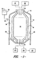
- FIG. 1 illustrates a simplified depiction of a gasifier 10 used to convert hydrocarbon feedstock into syngas.
- the gasifier 10 includes a pressure vessel 12 and an inner reaction chamber 14 defined by a brick insulation liner 16.
- the pressure vessel 12 generally defines the outer shell of the gasifier 10 and is configured to withstand the high pressures of the gasification process. Additionally, the pressure vessel 12 is configured to maintain the gases produced during the gasification process.
- the pressure vessel 12 is formed from a material, such as a steel alloy, that is not designed to withstand the high temperature reactions occurring within the reaction chamber 14.
- the brick insulation liner 16 of the gasifier 10 is generally configured to shield the pressure vessel 12 from the high temperatures produced during the process.
- brick insulation liner 16 generally comprises a high temperature insulation material, such as a high temperature ceramic, in order to ensure that the temperature at or near the pressure vessel 12 remains at a level that can be withstood by the vessel material.
- the gasifier 10 may include one or more inlets 18 for receiving a hydrocarbon feedstock, water (or stream), and oxygen and one or more outlets 20 for expelling the syngas produced by the gasification process as well as any by-products of the process, such as ash or slag (i.e. a water/ash mixture).
- coal from a coal source 21 is typically ground and combined with water to form a coal slurry.
- the coal slurry, as well as oxygen from an oxygen source 22, is directed into the gasifier 10 through the one or more inlets 18. Due at least in part to the heat and high pressure levels within the gasifier 10, the coal slurry and oxygen react to form hydrogen and carbon monoxide, the primary components of syngas.
- This high temperature syngas, along with the ash or slag produced during the process, may be expelled through the one or more outlets 20 of the gasifier 10.
- the slag or ash may be directed to a holding vessel 23.
- the syngas may be directed downstream to a syngas cooler 24 configured to cool the high temperature syngas so that it can be directed, for example, to downstream components 25 of an IGCC power plant, such as downstream piping, syngas cleaning devices and the like.
- corrosive gases such as ammonium chloride, hydrogen sulfide, hydrogen chloride and the like, may be produced. These gases may diffuse through the brick insulation liner 16 of the gasifier 10 and fill the space 26 defined between the pressure vessel 12 and the insulation liner 16. As indicated above, due to design constraints on the pressure vessel 12, the temperature at or near the pressure vessel 12 is maintained at a temperature significantly less than the temperature within the reaction chamber 14. Thus, the surface temperature of inner vessel wall(s) 28 may often be below the dew point of many of the corrosive gases contained within the pressure vessel 12. As such, the corrosive gases may condense as they come into contact with the relatively cool vessel wall 28.
- FIG. 1 also illustrates an embodiment of a system for online monitoring of corrosion of pressure vessel 12.
- the system generally includes a corrosion sensing device 30 at least partially disposed in the pressure vessel 12 and a corrosion monitoring device 32 coupled to the corrosion sensing device 30.
- the monitoring device 32 is configured to measure and analyze outputs from the sensing device 30 to predict the corrosion characteristics of the metal in which the sensing device 30 is installed. Based on the predicted corrosion characteristics, the monitoring device 32 then indicates when a corrective action is recommended or required to be performed on the gasifier 10 or the pressure vessel 12 in order to prevent damage due to excessive corrosion.
- the corrosion sensing device 30 is generally be disposed in the wall 28 of the pressure vessel 12 in order to predict the corrosion characteristics of the pressure vessel 12. Additionally, as illustrated, the corrosion sensing device 30 may be coupled to the corrosion monitoring device 32 by a wire. However, in alternative embodiments, the corrosion sensing device 30 may be in communication with the corrosion monitoring device 32 through a wireless transmitter, such as a radio-frequency transmitter. It should also be appreciated that multiple corrosion sensing devices 30 may be disposed within the gasifier 10, such as in the pressure vessel 12, to detect corrosion at various locations within the gasifier 10.
- FIG. 2 illustrates a cross-sectional view of a corrosion sensing device 30 disposed generally within the pressure vessel 12 of a gasifier 10.
- the corrosion sensing device 30 is installed or mounted within the vessel 12 such that one end of the sensing device 30 is exposed to the corrosive, condensing gaseous salt environment of the gasifier 10 during operation. The opposing end extends to the exterior of the pressure vessel 12.
- the corrosion sensing device 30 may be mounted within the pressure vessel 12 using any suitable means.
- the sensing device 30 is secured in the pressure vessel 12 by a swagelock-type compression fitting. In alternative embodiments, however, the corrosion sensing device 30 may be mounted within the vessel 12 utilizing a threaded fitting, by welding or by any other means known in the art.
- the corrosion sensing device 30 of the present subject matter may generally comprise a coupled multi-electrode array sensor for detecting corrosion and may be configured as such.
- the corrosion sensing device 30 may include an insulating material 38 and a plurality of electrodes 40.
- the insulating material 38 is generally made of any material that resists the flow of electrical current so as to electrically isolate the electrodes 40 within the sensing device 30.
- the insulating material 38 comprises a high temperature material.
- the insulating material 38 comprises a high temperature ceramic or some other suitable electrical insulator coated with a high temperature material.
- the electrodes 40 of the corrosion sensing device 30 may generally comprise small pieces of metal or wire. Generally, the electrodes 40 are disposed within the corrosion sensing device 30 such that each electrode 40 is isolated from other electrodes 40 by the insulating material 38. Additionally, although a single row of electrodes 40 is illustrated in FIG. 2 , it should be appreciated that the electrodes 40 may be arranged within the corrosion sensing device 30 as a two-dimensional array. Further, the spacing between adjacent electrodes 40 may generally vary. However, it should be appreciated that optimal spacing may be ascertainable through routine experimentation.
- the electrodes 40 are arranged in the corrosion sensing device 30 such that a portion of each electrode 40 is exposed to the corrosive, high temperature salts condensing within the pressure vessel 12, such as on the vessel wall 28.
- an end face 42 of each of the electrodes is exposed to the corrosive environment and is substantially aligned with the inner wall 28 of the pressure vessel 12.
- the end faces 42 are directly exposed to the corrosive agents contained within the pressure vessel 12 and, in particular, are directly exposed to the corrosive, high temperature gaseous salts condensing on the vessel wall 28.
- the corrosion sensing device 30 is configured to detect corrosion occurring in a pressure vessel 12.
- the corrosion sensing device 30 detects localized corrosion based on the electrochemical reactions occurring at the exposed faces 42 of the electrodes 40.
- the electrodes 40 are exposed to the corrosive salts condensing on the vessel wall 28 and, thus, undergo corrosion similar to that of the pressure vessel 12.
- some of the electrodes 40 within the corrosion sensing device 30 will have properties like the anodic sites in the base metal of the pressure vessel 12 and some of the electrodes will have properties like the cathodic sites of the base metal.
- the electrodes 40 when the electrodes 40 are electrically isolated from each other within the insulating material 38 but coupled together external to the insulating material 38, such as within the corrosion monitoring device 32, the electrodes 40 operable as anodes simulate the anodic areas and the electrodes 40 operable as cathodes simulate the cathodic areas of the base metal.
- the electrodes 40 operable as anodes when an electrical potential difference exists between the electrodes, due to corrosion occurring at one or more of the anode electrodes 40, an electrical current flows between the electrodes 40. Accordingly, the electrodes 40 operable as anodes release electrons that flow to the electrodes 40 operable as cathodes.
- the resulting electrical potential difference and/or electrical current between the anode electrodes 40 and the cathode electrodes 40 is then measured and analyzed by the corrosion monitoring device 32 to predict the extent of corrosion occurring on the pressure vessel 12 and thereby determine when a corrective action, if any, is required to be performed on the pressure vessel 12 or within the gasifier 12.
- the electrodes 40 are formed from a material having corrosion characteristics similar to those of the material used to form the pressure vessel 12.
- the electrodes 40 may be formed from a material having corrosion characteristics substantially similar to those of the pressure vessel 12.
- the electrodes 40 exhibit a corrosion behavior substantially similar to that of the pressure vessel 12 and, more particularly, exhibit a similar response to the corrosive gaseous salts responsible for much of the corrosion within a gasifier 10.
- the electrodes 40 are formed from the same material as the pressure vessel 12.
- the measurements taken from the corrosion sensing device 30 not only indicate the corrosion characteristics of the electrodes 40, but, by appropriately choosing the electrode material, are also used to accurately predict the extent of corrosion occurring at the vessel wall(s) 28 of the pressure vessel 12.
- the actual electrodes 40 may be formed from substantially different materials to permit the taking of corrosion measurements for multiple components using a single corrosion sensing device 30 and/or to allow additional information to be gathered relating to the corrosion occurring on the pressure vessel 12.
- a first set of electrodes 40 of the corrosion sensing device 30 is formed from the same material as the pressure vessel 12, while a second set is formed from the same material as a different component. As such, the electrical potential differences across and/or the electrical currents flowing between the first and second sets of electrodes 40 are measured in order to predict the extent of corrosion occurring on both components without necessitating the use of more than one sensing device 30.
- two or more sensing devices 30 are disposed in the pressure vessel 12, with at least one sensing device 30 including electrodes 40 formed from a material substantially similar to that of the pressure vessel 12 and at least one other sensing device 30 including electrodes 40 made of differing materials.
- the corrosion monitoring device 32 of the present subject matter is generally configured to measure and analyze the outputs from the corrosion sensing device (e.g. the electrical potential differences across and/or the electrical currents flowing between the electrodes 40).
- the corrosion monitoring device 32 is utilized to predict the corrosion characteristics of a pressure vessel 12 and thereby indicate when a corrective action(s) is recommended or required to be performed.
- the electrodes 40 of the corrosion sensing device 30 are electrically coupled within the corrosion monitoring device 32 such that the monitoring device 32 is capable of measuring the electrical potential difference and/or the electrical current flowing between any two electrodes 40 or the electrical potential difference and and/or the electrical current flowing between a plurality of electrodes 40 disposed within the corrosion sensing device 30.
- the corrosion monitoring device 32 comprises any device or combination of devices capable of measuring and analyzing the potential difference across and/or the electrical current flowing between the electrodes 40.
- the corrosion monitoring device 32 may comprise a voltmeter, ammeter or any other suitable electrical measuring instrument in communication with the gasifier controller of the gasifier control system, the IGCC controller of an IGCC power plant control system, a computer or any other suitable processing equipment.
- each of the electrodes 40 is electrically connected to a common lead (not illustrated), with a small resistor (not illustrated) connected between each electrode and the common lead.
- the output from each electrode 40 is delivered to a multi-channel voltmeter to permit the electrical potential difference or voltage drop across the resistor to be measured.
- the corrosion monitoring device 32 includes a multi-electrode corrosion monitor in communication with suitable processing equipment such that the potential difference and/or electrical current between electrodes 40 may be measured and analyzed.
- a suitable commercially available multi-electrode corrosion monitor comprises a NANOCORR from CORR INSTRUMENTS (San Antonio, Texas).
- the corrosion sensing device 30 is directly coupled to processing equipment that is capable of both measuring and analyzing outputs from the sensing device 30 in order to predict the corrosion characteristics of the pressure vessel 12. It should be appreciated that any processing equipment utilized with the system of the present subject matter, such as any computer-related equipment, may be configured to run any suitable set of software instructions for analyzing the potential differences and/or the electrical current between the electrodes 40.
- the corrosion sensing device 30 is generally configured to simulate the corroding base metal of a pressure vessel 12.
- the corrosion monitoring device 32 is employed to predict the corrosion characteristics of the pressure vessel 12, such as pitting rates and depths, by analyzing the current flow between and/or the electrical potential difference across the electrodes 40.
- a suitable transfer function may be developed and programmed into the corrosion monitoring device 32 to relate the electrical potential difference, the electrical current flowing between the electrodes 40 or both to the corrosion characteristics of the pressure vessel 12. The development of such transfer functions is within the capability of those skilled in the art, and therefore will not be discussed in any detail herein.
- average corrosion or pitting rates of the pressure vessel 12 may be predicted based on the average of the currents between the anodic and cathodic electrodes 40 and localized corrosion rates may be predicted based on the fastest corroding electrode 40 (i.e. the most anodic electrode from which electrons are lost at the highest rate). Additionally, corrosion or pitting depth may be predicted by reverse-calculating base metal loss at the anodic electrodes 40 via measuring current.
- the corrosion monitoring device 32 may also be capable of manipulating, storing and/or displaying the predicted corrosion characteristics and/or corrosion measurements so that such data may be accessed and understood by an operator or a maintenance worker.
- the corrosion monitoring device 32 includes a display device 33, such as a computer screen, display panel or other suitable visual display, which provides the operator with a visual indication of the extent of corrosion occurring on the pressure vessel 12.
- the corrosion monitoring device 32 is configured to display on the display device 33 a table or chart depicting the predicted pitting depth and/or pitting rate over time for the pressure vessel 12, for another monitored component, or for multiple monitored components. In such an embodiment, an operator may then determine what corrective action, if any, is necessary to respond to the displayed pitting rates and/or pitting depths.
- the corrosion monitoring device 32 may be programmed with suitable software instructions so as to automatically determine whether a corrective action is necessary based on, for example, predetermined limits for pitting depths and/or pitting rates for a particular component(s). As such, the corrosion monitoring device 32 may notify an operator or maintenance worker, via the display device 33, automatically of any recommended or required corrective actions to permit the operator or worker to take any necessary actions.
- the corrosion monitoring device 32 is utilized to indicate when a corrective action should be preformed on the pressure vessel 12 of the gasifier 10. This allows for both predictive/proactive maintenance of the pressure vessel 12 or gasifier 10, as well as the performance of reactive corrective actions based on, for example, a sudden or unexpected increase in corrosion levels.
- the corrective action taken may generally be any action directed towards preventing or reducing the amount of corrosion occurring on the pressure vessel 12 or any action directed to monitoring and/or inspecting the status of the pressure vessel 12.
- the corrective action may comprise shut down and inspection of the components of the gasifier 10.
- the corrective action may comprise altering one or more operating parameters of the gasifier 10, such as adjusting one or more of the following: the feed rate of the hydrocarbon feedstock, the feed rate of the oxygen, the pressure within the gasifier 10 and/or the amount of water supplied to the gasifier 10 (such as by adjusting the water content of the coal slurry).
- the gasifier 10 may be altered by adjusting one or more of the following: the feed rate of the hydrocarbon feedstock, the feed rate of the oxygen, the pressure within the gasifier 10 and/or the amount of water supplied to the gasifier 10 (such as by adjusting the water content of the coal slurry).
- the particular corrective action taken may depend on the type and/or extent of corrosion predicted for the pressure vessel 12. For example, it may be desirable to relate and/or assign certain corrective actions or a combination of corrective actions to a particular corrosion condition/rate/status to enable an operator (or the corrosion monitoring device 32) to determine when and what action should be taken.
- the corrective action may comprise the implementation of any available mitigation strategies, such as altering certain operating parameters of the gasifier 10.
- the gasifier 10 may be shut down and inspected to prevent additional pitting/damage to the pressure vessel 12.
- the corrective action may include investigation by the operator of any special causes for such an increase.
- the operating life of the pressure vessel 12 is predicted.
- a suitable transfer function may be developed to accurately predict the vessel life based, at least in part, on the corrosion measurements provided by the corrosion monitoring device 32.
Landscapes
- Life Sciences & Earth Sciences (AREA)
- Biodiversity & Conservation Biology (AREA)
- Ecology (AREA)
- Environmental & Geological Engineering (AREA)
- Environmental Sciences (AREA)
- Physics & Mathematics (AREA)
- Health & Medical Sciences (AREA)
- Chemical & Material Sciences (AREA)
- Analytical Chemistry (AREA)
- Biochemistry (AREA)
- General Health & Medical Sciences (AREA)
- General Physics & Mathematics (AREA)
- Immunology (AREA)
- Pathology (AREA)
- Testing Resistance To Weather, Investigating Materials By Mechanical Methods (AREA)
- Investigating Or Analyzing Materials By The Use Of Electric Means (AREA)
Applications Claiming Priority (1)
| Application Number | Priority Date | Filing Date | Title |
|---|---|---|---|
| US12/757,659 US7982474B1 (en) | 2010-04-09 | 2010-04-09 | System and method for online monitoring of corrosion |
Publications (3)
| Publication Number | Publication Date |
|---|---|
| EP2375234A2 EP2375234A2 (en) | 2011-10-12 |
| EP2375234A3 EP2375234A3 (en) | 2013-01-09 |
| EP2375234B1 true EP2375234B1 (en) | 2015-11-04 |
Family
ID=44146269
Family Applications (1)
| Application Number | Title | Priority Date | Filing Date |
|---|---|---|---|
| EP11161625.6A Not-in-force EP2375234B1 (en) | 2010-04-09 | 2011-04-08 | System and Method for Online Monitoring of Corrosion |
Country Status (4)
| Country | Link |
|---|---|
| US (1) | US7982474B1 (enExample) |
| EP (1) | EP2375234B1 (enExample) |
| JP (1) | JP5780792B2 (enExample) |
| CN (1) | CN102262045B (enExample) |
Families Citing this family (8)
| Publication number | Priority date | Publication date | Assignee | Title |
|---|---|---|---|---|
| US8224595B2 (en) * | 2010-04-09 | 2012-07-17 | General Electric Company | System and method for online monitoring of molten salt corrosion |
| US8390306B2 (en) | 2010-08-11 | 2013-03-05 | International Business Machines Corporation | Corrosion sensors |
| US20120053861A1 (en) * | 2010-08-26 | 2012-03-01 | Baker Hughes Incorporated | On-line monitoring and prediction of corrosion in overhead systems |
| CN102645514A (zh) * | 2012-03-15 | 2012-08-22 | 浙江大学 | 煤粉锅炉水冷壁烟气组分分布矩阵式检测装置及方法 |
| US9310288B2 (en) | 2013-01-28 | 2016-04-12 | Fisher-Rosemount Systems, Inc. | Systems and methods to monitor operating processes |
| CN107063984A (zh) * | 2017-03-13 | 2017-08-18 | 李铁骑 | 腐蚀传感器及腐蚀监测系统 |
| ES2907193T3 (es) | 2018-10-11 | 2022-04-22 | Dreve Prodimed Gmbh | Material para la producción aditiva de objetos tridimensionales, así como procedimiento para la producción y empleo |
| CN114964380B (zh) * | 2022-06-02 | 2023-06-13 | 上海发电设备成套设计研究院有限责任公司 | 一种管材高温腐蚀状态监测方法、装置及系统 |
Citations (1)
| Publication number | Priority date | Publication date | Assignee | Title |
|---|---|---|---|---|
| US5208162A (en) * | 1990-05-08 | 1993-05-04 | Purafil, Inc. | Method and apparatus for monitoring corrosion |
Family Cites Families (14)
| Publication number | Priority date | Publication date | Assignee | Title |
|---|---|---|---|---|
| EP0084404B1 (en) * | 1982-01-05 | 1989-05-31 | University Of Manchester Institute Of Science And Technology | Corrosion monitoring |
| EP0643825A1 (en) * | 1992-11-20 | 1995-03-22 | Westinghouse Electric Corporation | Apparatus and method for real time corrosion monitoring in high temperature systems |
| US5323429A (en) * | 1993-01-15 | 1994-06-21 | Westinghouse Electric Corporation | Electrochemical monitoring of vessel penetrations |
| JP3534373B2 (ja) * | 1996-11-15 | 2004-06-07 | 三菱化学株式会社 | 応力腐食割れ診断装置 |
| JPH1196843A (ja) * | 1997-09-19 | 1999-04-09 | Alps Electric Co Ltd | スイッチ |
| US6015484A (en) * | 1997-11-26 | 2000-01-18 | Gamry Instruments, Inc. | Detection of pitting corrosion |
| US6683463B2 (en) | 2001-03-27 | 2004-01-27 | Southwest Research Institute | Sensor array for electrochemical corrosion monitoring |
| JP2004028452A (ja) * | 2002-06-26 | 2004-01-29 | Mitsubishi Chemicals Corp | ボイラーチューブ管理システムを有するボイラー装置 |
| JP2005221381A (ja) * | 2004-02-05 | 2005-08-18 | Mitsubishi Chemicals Corp | 腐食監視方法 |
| JP2007532887A (ja) * | 2004-04-09 | 2007-11-15 | サウスウエスト リサーチ インスティテュート | 複数電極アレイ・センサを用いた局所腐食度を測定する改良された方法 |
| US8623185B2 (en) | 2005-10-12 | 2014-01-07 | Southwest Research Institute | Planar multi-electrode array sensor for localized electrochemical corrosion detection |
| JP4724649B2 (ja) * | 2006-12-21 | 2011-07-13 | 東京電力株式会社 | Acmセンサによる構造物の腐食速度推定方法 |
| EP2124034A1 (en) * | 2008-05-20 | 2009-11-25 | BAE Systems PLC | Corrosion sensors |
| US8224595B2 (en) * | 2010-04-09 | 2012-07-17 | General Electric Company | System and method for online monitoring of molten salt corrosion |
-
2010
- 2010-04-09 US US12/757,659 patent/US7982474B1/en not_active Expired - Fee Related
-
2011
- 2011-03-24 JP JP2011065320A patent/JP5780792B2/ja active Active
- 2011-04-08 EP EP11161625.6A patent/EP2375234B1/en not_active Not-in-force
- 2011-04-08 CN CN201110093302.4A patent/CN102262045B/zh not_active Expired - Fee Related
Patent Citations (1)
| Publication number | Priority date | Publication date | Assignee | Title |
|---|---|---|---|---|
| US5208162A (en) * | 1990-05-08 | 1993-05-04 | Purafil, Inc. | Method and apparatus for monitoring corrosion |
Non-Patent Citations (2)
| Title |
|---|
| BANYUK G F ET AL: "The capacities of a corrosion-fatigue monitoring system in managing the service life of steam generators operating at nuclear power stations equipped with a VVER-1000M reactor", THERMAL ENGINEERING, NAUKA/INTERPERIODICA, MO, vol. 54, no. 2, 1 February 2007 (2007-02-01), pages 99 - 103, XP019486640, ISSN: 1555-6301, DOI: 10.1134/S0040601507020036 * |
| SYRETT ET AL: "Corrosion control in electric power plants-success stories", CORROSION SCIENCE, OXFORD, GB, vol. 35, no. 5-8, 1 January 1993 (1993-01-01), pages 1189 - 1198, XP024047458, ISSN: 0010-938X, [retrieved on 19930101], DOI: 10.1016/0010-938X(93)90339-I * |
Also Published As
| Publication number | Publication date |
|---|---|
| CN102262045A (zh) | 2011-11-30 |
| CN102262045B (zh) | 2016-01-13 |
| US7982474B1 (en) | 2011-07-19 |
| EP2375234A3 (en) | 2013-01-09 |
| JP5780792B2 (ja) | 2015-09-16 |
| EP2375234A2 (en) | 2011-10-12 |
| JP2011219173A (ja) | 2011-11-04 |
Similar Documents
| Publication | Publication Date | Title |
|---|---|---|
| EP2375234B1 (en) | System and Method for Online Monitoring of Corrosion | |
| EP2280265B1 (en) | System and method for online monitoring of corrosion of gas turbine components | |
| US8224595B2 (en) | System and method for online monitoring of molten salt corrosion | |
| US10962505B2 (en) | Methods and systems for measuring corrosion in-situ | |
| CZ156294A3 (en) | Corrosion and a part material disintegration velocity in jet operation monitoring method and apparatus for making the same | |
| JP2011219173A5 (enExample) | ||
| JP4876011B2 (ja) | プラント運転方法 | |
| De Bruyn | Current corrosion monitoring trends in the petrochemical industry | |
| Marx et al. | Analysis and quantification of high-temperature corrosion in lignite fired boilers using an online monitoring system | |
| EP3314235A1 (en) | Corrosion rate measurement with multivariable sensor | |
| Eden et al. | Real-Time Corrosion Monitoring for Improved Process Control: A Real and Timely Alternative to Upgrading of Materials of Construction | |
| Hakimian et al. | Effect of temperature on the crevice corrosion propagation on flange faces | |
| Matthes et al. | Field test of high-temperature corrosion sensors in a waste-to-energy plant | |
| Zehra et al. | Corrosion Monitoring and Inspection Techniques in Industrial Environments | |
| Saluja et al. | Non-intrusive online corrosion monitoring | |
| Hernandez et al. | Real-time, online corrosion monitoring & process optimization through the chemical plant control system | |
| CN120232003A (zh) | 基于氧化还原电位法预测锅炉再热器氧化皮生成的系统 | |
| CN120994935A (zh) | 基于数字孪生的石墨换热器腐蚀速率预测系统及方法 | |
| Ashiru et al. | Corrosion Monitoring by Electrochemical Noise Probes in a Purified Teraphthalic Acid Production Plant | |
| Hofstötter et al. | In-service monitoring and fractographic inspection of ultrasonic indications on a feed water suction pipe of the Gundremmingen nuclear power plant | |
| Peatfield | Developments in real-time corrosion monitoring; recent advances in techniques and the management, display and correlation of data | |
| Nazef et al. | Critique Of Corrosion Monitoring Methods Used In Oil And Gas Production And Transportation Facilities |
Legal Events
| Date | Code | Title | Description |
|---|---|---|---|
| PUAI | Public reference made under article 153(3) epc to a published international application that has entered the european phase |
Free format text: ORIGINAL CODE: 0009012 |
|
| AK | Designated contracting states |
Kind code of ref document: A2 Designated state(s): AL AT BE BG CH CY CZ DE DK EE ES FI FR GB GR HR HU IE IS IT LI LT LU LV MC MK MT NL NO PL PT RO RS SE SI SK SM TR |
|
| AX | Request for extension of the european patent |
Extension state: BA ME |
|
| PUAL | Search report despatched |
Free format text: ORIGINAL CODE: 0009013 |
|
| AK | Designated contracting states |
Kind code of ref document: A3 Designated state(s): AL AT BE BG CH CY CZ DE DK EE ES FI FR GB GR HR HU IE IS IT LI LT LU LV MC MK MT NL NO PL PT RO RS SE SI SK SM TR |
|
| AX | Request for extension of the european patent |
Extension state: BA ME |
|
| RIC1 | Information provided on ipc code assigned before grant |
Ipc: G01N 17/02 20060101AFI20121130BHEP Ipc: B01J 3/04 20060101ALI20121130BHEP |
|
| 17P | Request for examination filed |
Effective date: 20130709 |
|
| RBV | Designated contracting states (corrected) |
Designated state(s): AL AT BE BG CH CY CZ DE DK EE ES FI FR GB GR HR HU IE IS IT LI LT LU LV MC MK MT NL NO PL PT RO RS SE SI SK SM TR |
|
| 17Q | First examination report despatched |
Effective date: 20131029 |
|
| GRAP | Despatch of communication of intention to grant a patent |
Free format text: ORIGINAL CODE: EPIDOSNIGR1 |
|
| INTG | Intention to grant announced |
Effective date: 20150709 |
|
| GRAS | Grant fee paid |
Free format text: ORIGINAL CODE: EPIDOSNIGR3 |
|
| GRAA | (expected) grant |
Free format text: ORIGINAL CODE: 0009210 |
|
| AK | Designated contracting states |
Kind code of ref document: B1 Designated state(s): AL AT BE BG CH CY CZ DE DK EE ES FI FR GB GR HR HU IE IS IT LI LT LU LV MC MK MT NL NO PL PT RO RS SE SI SK SM TR |
|
| REG | Reference to a national code |
Ref country code: GB Ref legal event code: FG4D |
|
| REG | Reference to a national code |
Ref country code: CH Ref legal event code: EP |
|
| REG | Reference to a national code |
Ref country code: AT Ref legal event code: REF Ref document number: 759533 Country of ref document: AT Kind code of ref document: T Effective date: 20151115 |
|
| REG | Reference to a national code |
Ref country code: IE Ref legal event code: FG4D |
|
| REG | Reference to a national code |
Ref country code: DE Ref legal event code: R096 Ref document number: 602011021094 Country of ref document: DE |
|
| REG | Reference to a national code |
Ref country code: NL Ref legal event code: MP Effective date: 20151104 |
|
| REG | Reference to a national code |
Ref country code: LT Ref legal event code: MG4D |
|
| REG | Reference to a national code |
Ref country code: AT Ref legal event code: MK05 Ref document number: 759533 Country of ref document: AT Kind code of ref document: T Effective date: 20151104 |
|
| PG25 | Lapsed in a contracting state [announced via postgrant information from national office to epo] |
Ref country code: HR Free format text: LAPSE BECAUSE OF FAILURE TO SUBMIT A TRANSLATION OF THE DESCRIPTION OR TO PAY THE FEE WITHIN THE PRESCRIBED TIME-LIMIT Effective date: 20151104 Ref country code: NO Free format text: LAPSE BECAUSE OF FAILURE TO SUBMIT A TRANSLATION OF THE DESCRIPTION OR TO PAY THE FEE WITHIN THE PRESCRIBED TIME-LIMIT Effective date: 20160204 Ref country code: NL Free format text: LAPSE BECAUSE OF FAILURE TO SUBMIT A TRANSLATION OF THE DESCRIPTION OR TO PAY THE FEE WITHIN THE PRESCRIBED TIME-LIMIT Effective date: 20151104 Ref country code: ES Free format text: LAPSE BECAUSE OF FAILURE TO SUBMIT A TRANSLATION OF THE DESCRIPTION OR TO PAY THE FEE WITHIN THE PRESCRIBED TIME-LIMIT Effective date: 20151104 Ref country code: LT Free format text: LAPSE BECAUSE OF FAILURE TO SUBMIT A TRANSLATION OF THE DESCRIPTION OR TO PAY THE FEE WITHIN THE PRESCRIBED TIME-LIMIT Effective date: 20151104 Ref country code: IS Free format text: LAPSE BECAUSE OF FAILURE TO SUBMIT A TRANSLATION OF THE DESCRIPTION OR TO PAY THE FEE WITHIN THE PRESCRIBED TIME-LIMIT Effective date: 20160304 |
|
| PG25 | Lapsed in a contracting state [announced via postgrant information from national office to epo] |
Ref country code: PL Free format text: LAPSE BECAUSE OF FAILURE TO SUBMIT A TRANSLATION OF THE DESCRIPTION OR TO PAY THE FEE WITHIN THE PRESCRIBED TIME-LIMIT Effective date: 20151104 Ref country code: GR Free format text: LAPSE BECAUSE OF FAILURE TO SUBMIT A TRANSLATION OF THE DESCRIPTION OR TO PAY THE FEE WITHIN THE PRESCRIBED TIME-LIMIT Effective date: 20160205 Ref country code: AT Free format text: LAPSE BECAUSE OF FAILURE TO SUBMIT A TRANSLATION OF THE DESCRIPTION OR TO PAY THE FEE WITHIN THE PRESCRIBED TIME-LIMIT Effective date: 20151104 Ref country code: LV Free format text: LAPSE BECAUSE OF FAILURE TO SUBMIT A TRANSLATION OF THE DESCRIPTION OR TO PAY THE FEE WITHIN THE PRESCRIBED TIME-LIMIT Effective date: 20151104 Ref country code: RS Free format text: LAPSE BECAUSE OF FAILURE TO SUBMIT A TRANSLATION OF THE DESCRIPTION OR TO PAY THE FEE WITHIN THE PRESCRIBED TIME-LIMIT Effective date: 20151104 Ref country code: FI Free format text: LAPSE BECAUSE OF FAILURE TO SUBMIT A TRANSLATION OF THE DESCRIPTION OR TO PAY THE FEE WITHIN THE PRESCRIBED TIME-LIMIT Effective date: 20151104 Ref country code: PT Free format text: LAPSE BECAUSE OF FAILURE TO SUBMIT A TRANSLATION OF THE DESCRIPTION OR TO PAY THE FEE WITHIN THE PRESCRIBED TIME-LIMIT Effective date: 20160304 Ref country code: SE Free format text: LAPSE BECAUSE OF FAILURE TO SUBMIT A TRANSLATION OF THE DESCRIPTION OR TO PAY THE FEE WITHIN THE PRESCRIBED TIME-LIMIT Effective date: 20151104 |
|
| PG25 | Lapsed in a contracting state [announced via postgrant information from national office to epo] |
Ref country code: CZ Free format text: LAPSE BECAUSE OF FAILURE TO SUBMIT A TRANSLATION OF THE DESCRIPTION OR TO PAY THE FEE WITHIN THE PRESCRIBED TIME-LIMIT Effective date: 20151104 |
|
| REG | Reference to a national code |
Ref country code: DE Ref legal event code: R097 Ref document number: 602011021094 Country of ref document: DE |
|
| PG25 | Lapsed in a contracting state [announced via postgrant information from national office to epo] |
Ref country code: SM Free format text: LAPSE BECAUSE OF FAILURE TO SUBMIT A TRANSLATION OF THE DESCRIPTION OR TO PAY THE FEE WITHIN THE PRESCRIBED TIME-LIMIT Effective date: 20151104 Ref country code: BE Free format text: LAPSE BECAUSE OF NON-PAYMENT OF DUE FEES Effective date: 20160430 Ref country code: EE Free format text: LAPSE BECAUSE OF FAILURE TO SUBMIT A TRANSLATION OF THE DESCRIPTION OR TO PAY THE FEE WITHIN THE PRESCRIBED TIME-LIMIT Effective date: 20151104 Ref country code: RO Free format text: LAPSE BECAUSE OF FAILURE TO SUBMIT A TRANSLATION OF THE DESCRIPTION OR TO PAY THE FEE WITHIN THE PRESCRIBED TIME-LIMIT Effective date: 20151104 Ref country code: DK Free format text: LAPSE BECAUSE OF FAILURE TO SUBMIT A TRANSLATION OF THE DESCRIPTION OR TO PAY THE FEE WITHIN THE PRESCRIBED TIME-LIMIT Effective date: 20151104 Ref country code: SK Free format text: LAPSE BECAUSE OF FAILURE TO SUBMIT A TRANSLATION OF THE DESCRIPTION OR TO PAY THE FEE WITHIN THE PRESCRIBED TIME-LIMIT Effective date: 20151104 |
|
| PLBE | No opposition filed within time limit |
Free format text: ORIGINAL CODE: 0009261 |
|
| STAA | Information on the status of an ep patent application or granted ep patent |
Free format text: STATUS: NO OPPOSITION FILED WITHIN TIME LIMIT |
|
| 26N | No opposition filed |
Effective date: 20160805 |
|
| PG25 | Lapsed in a contracting state [announced via postgrant information from national office to epo] |
Ref country code: SI Free format text: LAPSE BECAUSE OF FAILURE TO SUBMIT A TRANSLATION OF THE DESCRIPTION OR TO PAY THE FEE WITHIN THE PRESCRIBED TIME-LIMIT Effective date: 20151104 |
|
| REG | Reference to a national code |
Ref country code: CH Ref legal event code: PL |
|
| GBPC | Gb: european patent ceased through non-payment of renewal fee |
Effective date: 20160408 |
|
| PG25 | Lapsed in a contracting state [announced via postgrant information from national office to epo] |
Ref country code: BE Free format text: LAPSE BECAUSE OF FAILURE TO SUBMIT A TRANSLATION OF THE DESCRIPTION OR TO PAY THE FEE WITHIN THE PRESCRIBED TIME-LIMIT Effective date: 20151104 Ref country code: LU Free format text: LAPSE BECAUSE OF FAILURE TO SUBMIT A TRANSLATION OF THE DESCRIPTION OR TO PAY THE FEE WITHIN THE PRESCRIBED TIME-LIMIT Effective date: 20160408 |
|
| REG | Reference to a national code |
Ref country code: IE Ref legal event code: MM4A |
|
| REG | Reference to a national code |
Ref country code: FR Ref legal event code: ST Effective date: 20161230 |
|
| PG25 | Lapsed in a contracting state [announced via postgrant information from national office to epo] |
Ref country code: LI Free format text: LAPSE BECAUSE OF NON-PAYMENT OF DUE FEES Effective date: 20160430 Ref country code: FR Free format text: LAPSE BECAUSE OF NON-PAYMENT OF DUE FEES Effective date: 20160502 Ref country code: CH Free format text: LAPSE BECAUSE OF NON-PAYMENT OF DUE FEES Effective date: 20160430 Ref country code: GB Free format text: LAPSE BECAUSE OF NON-PAYMENT OF DUE FEES Effective date: 20160408 |
|
| PG25 | Lapsed in a contracting state [announced via postgrant information from national office to epo] |
Ref country code: IE Free format text: LAPSE BECAUSE OF NON-PAYMENT OF DUE FEES Effective date: 20160408 |
|
| PG25 | Lapsed in a contracting state [announced via postgrant information from national office to epo] |
Ref country code: HU Free format text: LAPSE BECAUSE OF FAILURE TO SUBMIT A TRANSLATION OF THE DESCRIPTION OR TO PAY THE FEE WITHIN THE PRESCRIBED TIME-LIMIT; INVALID AB INITIO Effective date: 20110408 Ref country code: CY Free format text: LAPSE BECAUSE OF FAILURE TO SUBMIT A TRANSLATION OF THE DESCRIPTION OR TO PAY THE FEE WITHIN THE PRESCRIBED TIME-LIMIT Effective date: 20151104 |
|
| PG25 | Lapsed in a contracting state [announced via postgrant information from national office to epo] |
Ref country code: TR Free format text: LAPSE BECAUSE OF FAILURE TO SUBMIT A TRANSLATION OF THE DESCRIPTION OR TO PAY THE FEE WITHIN THE PRESCRIBED TIME-LIMIT Effective date: 20151104 Ref country code: MC Free format text: LAPSE BECAUSE OF FAILURE TO SUBMIT A TRANSLATION OF THE DESCRIPTION OR TO PAY THE FEE WITHIN THE PRESCRIBED TIME-LIMIT Effective date: 20151104 Ref country code: MT Free format text: LAPSE BECAUSE OF NON-PAYMENT OF DUE FEES Effective date: 20160430 Ref country code: MK Free format text: LAPSE BECAUSE OF FAILURE TO SUBMIT A TRANSLATION OF THE DESCRIPTION OR TO PAY THE FEE WITHIN THE PRESCRIBED TIME-LIMIT Effective date: 20151104 |
|
| PG25 | Lapsed in a contracting state [announced via postgrant information from national office to epo] |
Ref country code: BG Free format text: LAPSE BECAUSE OF FAILURE TO SUBMIT A TRANSLATION OF THE DESCRIPTION OR TO PAY THE FEE WITHIN THE PRESCRIBED TIME-LIMIT Effective date: 20151104 |
|
| PGFP | Annual fee paid to national office [announced via postgrant information from national office to epo] |
Ref country code: DE Payment date: 20180427 Year of fee payment: 8 |
|
| PGFP | Annual fee paid to national office [announced via postgrant information from national office to epo] |
Ref country code: IT Payment date: 20180423 Year of fee payment: 8 |
|
| PG25 | Lapsed in a contracting state [announced via postgrant information from national office to epo] |
Ref country code: AL Free format text: LAPSE BECAUSE OF FAILURE TO SUBMIT A TRANSLATION OF THE DESCRIPTION OR TO PAY THE FEE WITHIN THE PRESCRIBED TIME-LIMIT Effective date: 20151104 |
|
| REG | Reference to a national code |
Ref country code: DE Ref legal event code: R119 Ref document number: 602011021094 Country of ref document: DE |
|
| PG25 | Lapsed in a contracting state [announced via postgrant information from national office to epo] |
Ref country code: DE Free format text: LAPSE BECAUSE OF NON-PAYMENT OF DUE FEES Effective date: 20191101 |
|
| PG25 | Lapsed in a contracting state [announced via postgrant information from national office to epo] |
Ref country code: IT Free format text: LAPSE BECAUSE OF NON-PAYMENT OF DUE FEES Effective date: 20190408 |