EP2374936B2 - Fräswalze für eine Bodenfräsmaschine und Bodenfräsmaschine - Google Patents
Fräswalze für eine Bodenfräsmaschine und Bodenfräsmaschine Download PDFInfo
- Publication number
- EP2374936B2 EP2374936B2 EP11002790.1A EP11002790A EP2374936B2 EP 2374936 B2 EP2374936 B2 EP 2374936B2 EP 11002790 A EP11002790 A EP 11002790A EP 2374936 B2 EP2374936 B2 EP 2374936B2
- Authority
- EP
- European Patent Office
- Prior art keywords
- milling
- drum
- face
- circumferential surface
- hollow
- Prior art date
- Legal status (The legal status is an assumption and is not a legal conclusion. Google has not performed a legal analysis and makes no representation as to the accuracy of the status listed.)
- Active
Links
Images

Classifications
-
- E—FIXED CONSTRUCTIONS
- E01—CONSTRUCTION OF ROADS, RAILWAYS, OR BRIDGES
- E01C—CONSTRUCTION OF, OR SURFACES FOR, ROADS, SPORTS GROUNDS, OR THE LIKE; MACHINES OR AUXILIARY TOOLS FOR CONSTRUCTION OR REPAIR
- E01C23/00—Auxiliary devices or arrangements for constructing, repairing, reconditioning, or taking-up road or like surfaces
- E01C23/06—Devices or arrangements for working the finished surface; Devices for repairing or reconditioning the surface of damaged paving; Recycling in place or on the road
- E01C23/08—Devices or arrangements for working the finished surface; Devices for repairing or reconditioning the surface of damaged paving; Recycling in place or on the road for roughening or patterning; for removing the surface down to a predetermined depth high spots or material bonded to the surface, e.g. markings; for maintaining earth roads, clay courts or like surfaces by means of surface working tools, e.g. scarifiers, levelling blades
- E01C23/085—Devices or arrangements for working the finished surface; Devices for repairing or reconditioning the surface of damaged paving; Recycling in place or on the road for roughening or patterning; for removing the surface down to a predetermined depth high spots or material bonded to the surface, e.g. markings; for maintaining earth roads, clay courts or like surfaces by means of surface working tools, e.g. scarifiers, levelling blades using power-driven tools, e.g. vibratory tools
- E01C23/088—Rotary tools, e.g. milling drums
-
- B—PERFORMING OPERATIONS; TRANSPORTING
- B28—WORKING CEMENT, CLAY, OR STONE
- B28D—WORKING STONE OR STONE-LIKE MATERIALS
- B28D1/00—Working stone or stone-like materials, e.g. brick, concrete or glass, not provided for elsewhere; Machines, devices, tools therefor
- B28D1/18—Working stone or stone-like materials, e.g. brick, concrete or glass, not provided for elsewhere; Machines, devices, tools therefor by milling, e.g. channelling by means of milling tools
-
- B—PERFORMING OPERATIONS; TRANSPORTING
- B65—CONVEYING; PACKING; STORING; HANDLING THIN OR FILAMENTARY MATERIAL
- B65H—HANDLING THIN OR FILAMENTARY MATERIAL, e.g. SHEETS, WEBS, CABLES
- B65H23/00—Registering, tensioning, smoothing or guiding webs
- B65H23/02—Registering, tensioning, smoothing or guiding webs transversely
- B65H23/022—Registering, tensioning, smoothing or guiding webs transversely by tentering devices
- B65H23/025—Registering, tensioning, smoothing or guiding webs transversely by tentering devices by rollers
- B65H23/0251—Registering, tensioning, smoothing or guiding webs transversely by tentering devices by rollers with a straight axis
-
- B—PERFORMING OPERATIONS; TRANSPORTING
- B65—CONVEYING; PACKING; STORING; HANDLING THIN OR FILAMENTARY MATERIAL
- B65H—HANDLING THIN OR FILAMENTARY MATERIAL, e.g. SHEETS, WEBS, CABLES
- B65H2404/00—Parts for transporting or guiding the handled material
- B65H2404/10—Rollers
- B65H2404/11—Details of cross-section or profile
- B65H2404/115—Details of cross-section or profile other
- B65H2404/1151—Details of cross-section or profile other brush
Definitions
- the invention relates to a milling drum according to the type specified by the preamble of claim 1.
- the invention also relates to a soil milling machine with at least one such milling drum.
- Milling drums of the type in question are used to crush and/or remove soil material, in particular compacted or solid soil material, such as a concrete or tar surface. Such milling drums are often used to remove or partially remove a road surface (or the like). Such milling drums are known, for example, from the DE 698 24 340 T2 , the US 5,775,781 B and the DE 296 13 658 U known.
- a disadvantage of the milling drums of the type in question known from the state of the art is that they are exposed to severe wear during milling operation, especially on the front sides of the drum base body (also known as the drum). Particularly when cornering with a relatively small curve radii (e.g. milling free manhole covers), there is severe abrasion on the front side of the drum on the inside of the curve due to the milling edge formed in the ground material. The abrasion is increased by an undercut in the ground material (so-called undercut) in relation to the milling edge. Attempts are currently being made to protect the front sides of the drum from excessive wear by attaching wear plates. However, this is only partially satisfactory.
- a further disadvantage of the milling drums of the type in question known from the state of the art is that more milled material adheres to the milling drum box.
- the invention is therefore based on the object of further developing a milling drum of the type in question in such a way that the frontal wear on the drum is reduced.
- the milling drum according to the invention comprises a hollow cylindrical and axially extending drum base body, the so-called drum, which is defined with respect to its longitudinal axis by an inner drum radius and an outer drum radius.
- Several milling chisels are attached to the outer peripheral surface or the lateral surface of the hollow cylindrical drum for Crushing and/or removing soil material.
- two front-side milling chisels are arranged in the area of at least one circular end face of the hollow cylindrical bandage, which protrude from the relevant end face or protrude outwards from this end face and which, during milling operation, protect the relevant end face from direct abrasive contact with the soil material to be processed by the contact area or collision area between this end face of the hollow cylindrical bandage and the soil material being virtually cleared or cut free by these two front-side milling chisels.
- the relevant end face of the hollow cylindrical bandage is thereby at least partially protected from abrasion, whereby excessive wear on the relevant end face, as well as on any chisel holders and weld seams on the relevant end face, is avoided or at least significantly reduced.
- An essential aspect of the invention is the direct protection of the relevant front side of the hollow cylindrical drum by two front-side milling cutters, which is why the milling drum according to the invention is particularly suitable for cornering with a relatively small curve radius (e.g. milling free of manhole covers), despite the undercut on the milling edge.
- a relatively small curve radius e.g. milling free of manhole covers
- the two front-side milling cutters are arranged at equal intervals in a circumferential direction.
- the first front-side milling chisel is arranged on at least one front side of the hollow cylindrical bandage in the radial direction (with respect to the longitudinal axis or the axis of rotation of the hollow cylindrical bandage) approximately centrally between the inner radius of the bandage and the outer radius of the bandage or between the inner circumferential surface and the outer circumferential surface of the hollow cylindrical bandage.
- the cutting circle produced by this front-side milling chisel is located approximately centrally on the circular ring-shaped front side of the hollow cylindrical bandage.
- the two front-side milling cutters are arranged directly in the bandage on the front side of the hollow cylindrical bandage.
- the hollow cylindrical bandage is designed accordingly on the front side in question and has pockets, as explained in more detail below in connection with the figures.
- the two front-side milling chisels arranged on the front side of the hollow cylindrical bandage are designed as replaceable milling chisels.
- chisel change holders are arranged on the hollow cylindrical bandage, to which the replaceable front-side milling chisels are attached.
- the axial longitudinal extension of the milling drum is greater than the (maximum) diameter of this milling drum.
- the axial longitudinal extension is several times greater.
- the axial longitudinal extension of the milling drum is smaller than the (maximum) diameter of this milling drum.
- a milling drum can also be referred to as a milling rotor.
- the solution to the problem also extends to a ground milling machine with a driver's platform (large milling machine), comprising at least one milling drum according to the invention.
- a ground milling machine with a driver's platform large milling machine
- This is in particular a road milling machine.
- the solution to the problem also extends to a hand-held ground milling machine (compact milling machine), comprising at least one milling drum according to the invention.
- a hand-held ground milling machine comprising at least one milling drum according to the invention.
- This is in particular a road milling machine.
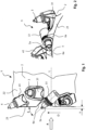
- Fig. 1 shows a milling drum according to the invention, designated overall by 1.
- the milling drum 1 includes a drum base body which is designed as a hollow cylindrical drum 2 and on whose outer circumferential surface or lateral surface 22 several milling chisels 3 and 4 are arranged for crushing and/or removing soil material.
- the milling chisels 3 and 4 are, for example, replaceable milling chisels which are attached to the drum 2 by means of chisel change holders 31 and 41.
- the chisel change holders 31 and 41 are in turn welded to the drum 2, for example.
- the longitudinal axis of the milling drum 1 and the drum 2 is indicated by L.
- the longitudinal axis L coincides with the axis of rotation.
- the direction of rotation (or direction of revolution or milling direction) of the milling drum 1 for milling operation is indicated by D.
- the milling chisels 3 are aligned with their milling chisel longitudinal axes essentially in the direction of rotation D, for example.
- the milling chisels 3 can also be angled with respect to the direction of rotation D.
- the left front side of the drum 2 is designated with 21.
- the angled milling chisels 4, which protrude beyond the front side 21, serve to create a defined milling edge in the soil material to be worked. However, no protection for the front side 21 can be achieved using these milling chisels 4.
- two front milling chisels 5a and 5b are arranged in the front area.
- the front-side milling chisels 5a and 5b protrude beyond the left front side 21 by a defined amount x (e.g. several millimeters) and are intended to at least partially cut or clear the collision area between this front side 21 and the soil material to be processed during milling operation in order to prevent direct contact between the front side 21 and the soil material remaining during milling. essentially to avoid.
- x e.g. several millimeters
- the relevant collision area on the front side 21 is indicated as radial section T (which essentially corresponds to the thickness of the drum 2).
- the front-side milling cutters 5a and 5b can cut free an area that exceeds this radial section T radially inwards and/or radially outwards.
- the front milling cutters 5a and 5b are also designed as exchangeable milling cutters, which are attached to the drum 2 by means of cutter change holders 51.
- the cutter change holders 51 are arranged in pockets 6a and 6b, as described below in connection with the Fig. 4
- the front milling cutters 5a and 5b are angled at an angle ⁇ relative to the direction of rotation D or are inclined outwards relative to the plane of the left front side 21, as can be clearly seen from the illustration of the Fig. 1
- the angle of attack ⁇ can be the same or different for both front-side milling cutters 5a and 5b. For milling drums with a large diameter or for milling drums with thick drums, more than the two front-side milling cutters may be required to clear the collision area.
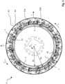
- Fig. 3 shows a plan view of the left front side 21 of the milling drum 1, according to the Fig. 1 viewing direction indicated by A.
- the bandage 2 is defined by an inner circumferential surface with a bandage inner radius Ri and an outer circumferential surface 22 with a bandage outer radius Ra.
- one drive disk 7 is present, which connects the bandage 2 to a rotary drive and/or to a suspension.
Landscapes
- Engineering & Computer Science (AREA)
- Mining & Mineral Resources (AREA)
- Mechanical Engineering (AREA)
- Architecture (AREA)
- Civil Engineering (AREA)
- Structural Engineering (AREA)
- Road Repair (AREA)
- Milling Processes (AREA)
- Shovels (AREA)
Description
- Die Erfindung betrifft eine Fräswalze gemäß der durch den Oberbegriff des Anspruchs 1 angegebenen Art. Die Erfindung betrifft ferner auch eine Bodenfräsmaschine mit wenigstens einer solchen Fräswalze.
- Fräswalzen der betreffenden Art dienen zum Zerkleinern und/oder Abtragen eines Bodenmaterials, insbesondere eines verdichteten oder festen Bodenmaterials, wie z. B. einer Beton- oder Teerdecke. Häufig werden solche Fräswalzen zur Entfernung oder teilweisen Entfernung eines Straßenbelags (oder dergleichen) eingesetzt. Solche Fräswalzen sind z. B. aus der
DE 698 24 340 T2 , derUS 5,775,781 B und derDE 296 13 658 U bekannt. - Nachteilig an den aus dem Stand der Technik bekannten Fräswalzen der betreffenden Art ist, dass diese im Fräsbetrieb vor allem an den Stirnseiten des Walzengrundkörpers (auch als Bandage bezeichnet) einem starken Verschleiß ausgesetzt sind. Vor allem bei Kurvenfahrten mit verhältnismäßig kleinem Kurvenradius (bspw. Freifräsen von Kanaldeckeln) kommt es zu einer starken Abrasion an der kurveninneren Stirnseite der Bandage durch die gebildete Fräskante im Bodenmaterial. Die Abrasion wird durch eine sich im Bodenmaterial einstellende Unterschneidung (sog. Hinterschnitt) bezüglich der Fräskante verstärkt. Gegenwärtig wird versucht, die Stirnseiten der Bandage durch das Anbringen von Verschleißblechen vor einem übermäßigen Verschleiß zu schützen. Dies ist jedoch nur bedingt zufriedenstellend. Nachteilig an den aus dem Stand der Technik bekannten Fräswalzen der betreffenden Art ist ferner, dass mehr Fräsgut im Fräswalzenkasten anhaftet.
- Der Erfindung liegt daher die Aufgabe zugrunde, eine Fräswalze der betreffenden Art derart weiter zu entwickeln, dass der stirnseitige Verschleiß an der Bandage verringert wird.
- Diese Aufgabe wird bei einer Fräswalze der betreffenden Art erfindungsgemäß durch die Merkmale des Anspruchs 1 gelöst. Hiernach ist u.a. vorgesehen, dass an der hohlzylindrischen Bandage im Bereich wenigstens einer Stirnseite zwei stirnseitige Fräsmeißel angeordnet sind, die bezüglich dieser Stirnseite überstehen und die dazu vorgesehen sind, im Fräsbetrieb den Kollisionsbereich zwischen dieser Stirnseite und dem zu bearbeitenden Bodenmaterial zumindest teilweise frei zu schneiden.
- Die erfindungsgemäße Fräswalze umfasst einen hohlzylindrischen und sich axial längserstreckenden Walzengrundkörper, die sog. Bandage, die bezüglich ihrer Längsachse durch einen Bandageninnenradius und durch einen Bandagenaußenradius definiert ist. An der Außenumfangsfläche bzw. der Mantelfläche der hohlzylindrischen Bandage sind mehrere Fräsmeißel zum Zerkleinern und/oder Abtragen von Bodenmaterial angeordnet. Ferner sind erfindungsgemäß im Bereich wenigstens einer kreisringförmigen Stirnseite der hohlzylindrischen Bandage zwei stirnseitige Fräsmeißel angeordnet, die von der betreffenden Stirnseite abragen bzw. von dieser Stirnseite nach außen überstehen und die im Fräsbetrieb die betreffende Stirnseite vor einem direkten abrasiven Kontakt mit dem zu bearbeitenden Bodenmaterial schützen, indem der Kontaktbereich bzw. Kollisionsbereich zwischen dieser Stirnseite der hohlzylindrischen Bandage und dem Bodenmaterial durch diese zwei stirnseitigen Fräsmeißel quasi freigeräumt bzw. freigeschnitten werden. Hierdurch wird je nach Anordnung und Ausbildung solcher stirnseitigen Fräsmeißel die betreffende Stirnseite der hohlzylindrischen Bandage zumindest teilweise vor Abrasion geschützt, wodurch ein übermäßiger Verschleiß an der betreffenden Stirnseite, sowie an etwaigen Meißelhaltern und Schweißnähten an der betreffenden Stirnseite, vermieden oder zumindest deutlich verringert wird.
- Ein wesentlicher Aspekt der Erfindung ist der direkte Schutz der betreffenden Stirnseite der hohlzylindrischen Bandage durch zwei stirnseitige Fräsmeißel, weshalb sich die erfindungsgemäße Fräswalze insbesondere auch für Kurvenfahrten mit verhältnismäßig kleinem Kurvenradius (bspw. Freifräsen von Kanaldeckeln) eignet, trotz der gegebenen Hinterschneidung an der Fräskante.
- Nach einer bevorzugten Weiterbildung ist vorgesehen, dass die zwei stirnseitigen Fräsmeißel in einer Umfangsrichtung in gleichmäßigen Abständen verteilt angeordnet sind.
- Die Längsachse der hohlzylindrischen Bandage entspricht der Rotationsachse. Mit einem radialen Abstand ist der Wirkabstand eines stirnseitigen Fräsmeißels, d. h. der Abstand der Frässpitze bzw. des Wirkpunkts des Fräsmeißels von der Längsachse bzw. der Rotationsachse gemeint, der mit einem bestimmten Schnittkreis einhergeht. Durch einen unterschiedlichen radialen Abstand der stirnseitigen Fräsmeißel bewegen sich diese im Fräsbetrieb auf verschiedenen Umfangsbahnen, wodurch unterschiedliche Schnittkreise erzeugt werden. Dies kann insbesondere bei dickeren hohlzylindrischen Bandagen von Vorteil sein. Die Bandagendicke ist der radiale Abstand zwischen dem Bandageninnenradius und dem Bandagenaußenradius.
- Erfindungsgemäß ist vorgesehen, dass an wenigstens einer Stirnseite der hohlzylindrischen Bandage der erste stirnseitige Fräsmeißel in radialer Richtung (bezüglich der Längsachse bzw. der Rotationsachse der hohlzylindrischen Bandage) in etwa mittig zwischen dem Bandageninnenradius und dem Bandagenaußenradius bzw. zwischen der Innenumfangsfläche und der Außenumfangsfläche der hohlzylindrischen Bandage angeordnet ist. Der von diesem stirnseitigen Fräsmeißel erzeugte Schnittkreis liegt in etwa mittig der kreisringförmigen Stirnseite der hohlzylindrischen Bandage.
- Es ist erfindungsgemäß vorgesehen, dass an der Stirnseite der hohlzylindrischen Bandage der zweite stirnseitige Fräsmeißel in radialer Richtung (bezüglich der Längsachse bzw. der Rotationsachse der hohlzylindrischen Bandage) über den Bandagenaußenradius bzw. über die Außenumfangsfläche nach radial außen übersteht. Durch diesen radialen Überstand ist die betreffende Stirnseite noch besser gegen Abrasion geschützt. Der radiale Überstand liegt erfindungsgemäß im Bereich von 5 bis 15 mm und beträgt insbesondere in etwa 10 mm. Diese Angaben betreffen einen durch die Frässpitze des stirnseitigen Fräsmeißels bewirkten Wirkabstand.
- Nach einer bevorzugten Weiterbildung ist vorgesehen, dass an wenigstens einer Stirnseite der hohlzylindrischen Bandage wenigstens einer der stirnseitigen Fräsmeißel mit einem Anstellwinkel angeordnet ist. Der Anstellwinkel kann z. B. als Neigungswinkel der Fräsmeißellängsachse bezüglich einer Umfangsrichtung bzw. Umdrehungsrichtung der hohlzylindrischen Bandage im Fräsbetrieb definiert werden.
- Erfindungsgemäß ist vorgesehen, dass an der Stirnseite der hohlzylindrischen Bandage die zwei stirnseitigen Fräsmeißel direkt in der Bandage an der betreffenden Stirnseite angeordnet sind. Hierzu ist die hohlzylindrische Bandage an der betreffenden Stirnseite entsprechend ausgebildet und weist Taschen auf, wie nachfolgend im Zusammenhang mit den Figuren noch näher erläutert.
- Erfindungsgemäß ist es vorgesehen, dass die zwei an der Stirnseite der hohlzylindrischen Bandage angeordneten stirnseitigen Fräsmeißel als auswechselbare Fräsmeißel ausgebildet sind. Es sind hierzu an der hohlzylindrischen Bandage Meißelwechselhalter angeordnet, an denen die auswechselbaren stirnseitigen Fräsmeißel befestigt wird.
- Nach einer bevorzugten Weiterbildung ist vorgesehen, dass die axiale Längserstreckung der Fräswalze größer als der (maximale) Durchmesser dieser Fräswalze ist. Bevorzugt ist die axiale Längserstreckung um ein mehrzahliges Vielfaches größer.
- Nach einer anderen bevorzugten Weiterbildung ist vorgesehen, dass die axiale Längserstreckung der Fräswalze kleiner als der (maximale) Durchmesser dieser Fräswalze ist. Eine solche Fräswalze kann auch als Fräsrotor bezeichnet werden.
- Die Lösung der Aufgabe erstreckt sich auch auf eine Bodenfräsmaschine mit einem Fahrstand (Großfräse), umfassend wenigstens eine erfindungsgemäße Fräswalze. Hierbei handelt es sich insbesondere um eine Straßenfräsmaschine.
- Die Lösung der Aufgabe erstreckt sich ferner auch auf eine handgeführte Bodenfräsmaschine (Kompaktfräse), umfassend wenigstens eine erfindungsgemäße Fräswalze. Hierbei handelt es sich insbesondere um eine Straßenfräsmaschine.
- Nachfolgend wird die Erfindung beispielhaft anhand der Figuren näher beschrieben. Es zeigen:
-
Fig. 1 den Stirnseitenbereich einer erfindungsgemäßen Fräswalze in einer Seitenansicht; -
Fig. 2 eine perspektivische Teilansicht der linken Stirnseite der Fräswalze aus derFig. 1 , gemäß der in derFig. 1 angegebenen Blickrichtung (A); -
Fig. 3 eine Draufsicht auf die linke Stirnseite der Fräswalze aus derFig. 1 , gemäß der in derFig. 1 angegebenen Blickrichtung (A); und -
Fig. 4 eine perspektivische Ansicht auf die linke Stirnseite der Fräswalze aus derFig. 1 . -
Fig. 1 zeigt eine insgesamt mit 1 bezeichnete erfindungsgemäße Fräswalze. Zur Fräswalze 1 gehört ein Walzengrundkörper der als hohlzylindrische Bandage 2 ausgebildet ist und an dessen Außenumfangsfläche bzw. Mantelfläche 22 mehrere Fräsmeißel 3 und 4 zum Zerkleinern und/oder Abtragen eines Bodenmaterials angeordnet sind. Bei den Fräsmeißeln 3 und 4 handelt es sich beispielhaft um auswechselbare Fräsmeißel, die mittels von Meißelwechselhaltern 31 und 41 an der Bandage 2 befestigt sind. Die Meißelwechselhalter 31 und 41 sind ihrerseits z. B. an der Bandage 2 festgeschweißt. Die Längsachse der Fräswalze 1 und der Bandage 2 ist mit L angegeben. Die Längsachse L fällt mit der Rotationsachse zusammen. Die Rotationsrichtung (bzw. Umdrehungsrichtung oder Fräsrichtung) der Fräswalze 1 für den Fräsbetrieb ist mit D angegeben. Die Fräsmeißel 3 sind mit ihren Fräsmeißellängsachsen beispielhaft im Wesentlichen in der Umdrehungsrichtung D ausgerichtet. Alternativ können die Fräsmeißel 3 auch bezüglich der Umdrehungsrichtung D angewinkelt sein. Mit 21 ist die linke Stirnseite der Bandage 2 bezeichnet. Die angewinkelten und über die Stirnseite 21 hinausragenden Fräsmeißel 4 dienen zur Erzeugung einer definierten Fräskante im zu bearbeitenden Bodenmaterial. Mittels dieser Fräsmeißel 4 kann jedoch kein Schutz für die Stirnseite 21 erzielt werden. - Zum Schutz der Stirnseite 21 der Bandage 2 im Fräsbetrieb sind im stirnseitigen Bereich zwei stirnseitige Fräsmeißel 5a und 5b angeordnet. In der in
Fig. 1 gezeigten Darstellung ist nur der stirnseitige Fräsmeißel 5a sichtbar. Die stirnseitigen Fräsmeißel 5a und 5b überragen die linke Stirnseite 21 um einen definierten Betrag x (bspw. mehrere Millimeter) und sind dazu vorgesehen, im Fräsbetrieb den Kollisionsbereich zwischen dieser Stirnseite 21 und dem zu bearbeitenden Bodenmaterial zumindest teilweise frei zu schneiden bzw. frei zu räumen, um einen direkten Kontakt zwischen der Stirnseite 21 und dem bei der Fräsbearbeitung stehen bleibenden Bodenmaterial im Wesentlichen zu vermeiden. In derFig. 2 ist der relevante Kollisionsbereich an der Stirnseite 21 als Radialabschnitt T (entspricht im Wesentlichen der Dicke der Bandage 2) angegeben. Die stirnseitigen Fräsmeißel 5a und 5b können je nach Ausführung einen Bereich freischneiden, der diesen Radialabschnitt T nach radial innen und/oder nach radial außen überschreitet. - Die stirnseitigen Fräsmeißel 5a und 5b sind ebenfalls als auswechselbare Fräsmeißel ausgeführt, die mittels von Meißelwechselhaltern 51 an der Bandage 2 befestigt sind. Die Meißelwechselhalter 51 sind in Taschen 6a und 6b angeordnet, wie nachfolgend im Zusammenhang mit der
Fig. 4 noch näher erläutert. Die stirnseitigen Fräsmeißel 5a und 5b sind mit einem Anstellwinkel β gegenüber der Umdrehungsrichtung D angewinkelt bzw. gegenüber der Ebene der linken Stirnseite 21 nach außen geneigt, wie sehr gut aus der Darstellung derFig. 1 ersichtlich. Der Anstellwinkel β kann für beide stirnseitige Fräsmeißel 5a und 5b gleich oder unterschiedlich sein. Bei Fräswalzen mit großem Durchmesser oder bei Fräswalzen mit dicken Bandagen können ggf. mehr als die zwei stirnseitigen Fräsmeißel erforderlich sein, um den Kollisionsbereich frei zu schneiden. -
Fig. 3 zeigt eine Draufsicht auf die linke Stirnseite 21 der Fräswalze 1, gemäß der in derFig. 1 mit A angegebenen Blickrichtung. In dieser Darstellung ist sehr gut der kreisringförmige Querschnitt der Bandage 2 zu erkennen. Die Bandage 2 ist durch eine Innenumfangsfläche mit einem Bandageninnenradius Ri und eine Außenumfangsfläche 22 mit einem Bandagenaußenradius Ra definiert. Ferner ist (wenigstens) eine Triebscheibe 7 vorhanden, welche die Verbindung der Bandage 2 mit einem Rotationsantrieb und/oder mit einer Aufhängung bewerkstelligt. - In
Fig. 3 ist mit K3 ein äußerer Fräs- bzw. Schnittkreis bezeichnet, der im Fräsbetrieb durch die an der Außenumfangsfläche 22 der Bandage 2 angeordneten Fräsmeißel 3 erzeugt wird. Mit K4 ist ein seitlicher Fräs- bzw. Schnittkreis bezeichnet, der im Fräsbetrieb durch die bezüglich der linken Stirnseite 21 leicht nach außen geneigten Fräsmeißel 4 erzeugt wird, was zu einer sauberen Fräskante im Bodenmaterial führen soll. - Mit den Fräsmeißeln 4 kann die Stirnseite 21 der Bandage 2 jedoch nicht vor Abrasion geschützt werden. Hierzu sind die stirnseitigen Fräsmeißel 5a und 5b vorgesehen. Wie aus der Darstellung der
Fig. 3 ersichtlich, sind die stirnseitigen Fräsmeißel 5a und 5b um etwa 180° versetzt im stirnseitigen Bereich der Bandage 2 angeordnet. - Mit K5b ist der Fräs- bzw. Schnittkreis des stirnseitigen Fräsmeißels 5b bezeichnet, der um wenige Millimeter radial außerhalb der Außenumfangsfläche 22 der Bandage 2 liegt. Mit K5a ist der Fräs- bzw. Schnittkreis des anderen stirnseitigen Fräsmeißels 5a bezeichnet, der sich in etwa mittig zwischen der Innenumfangsfläche und der Außenumfangsfläche 22 der Bandage 2 befindet. In gleicher Weise könnte ein weiterer stirnseitiger Fräsmeißel auch so angeordnet sein, dass sich der im Fräsbetrieb ergebende Fräs- bzw. Schnittkreis Kx radial innerhalb der Innenumfangsfläche der Bandage 2 befindet. Die Frässpitzen und damit die Wirkpunkte der stirnseitigen Fräsmeißel 5a und 5b befinden sich somit in unterschiedlichen radialen Abständen zur Längsachse bzw. Rotationsachse L. Durch die stirnseitigen Fräsmeißel 5a und 5b ist die betreffende linke Stirnseite 21 der Bandage 2 vor Abrasion im Fräsbetrieb geschützt, wodurch ein übermäßiger Verschleiß an dieser Stirnseite und an etwaigen Meißelhaltern bzw. Meißelwechselhaltern 31 und 41 sowie Schweißnähten im Bereich dieser Stirnseite 21 vermieden oder zumindest stark vermindert wird. Bevorzugt sind entsprechende stirnseitige Fräsmeißel auch an der anderen Stirnseite der Fräswalze 1 vorgesehen.
- Wie ferner sehr gut aus der
Fig. 3 ersichtlich ist, sind die Fräsmeißel 3 und 4 bezüglich einer radialen Richtung r geneigt, wobei die seitlich nach außen geneigten Fräsmeißel 4 stärker als die Fräsmeißel 3 geneigt sind und wobei die Frässpitzen jeweils in die Umdrehungsrichtung U bzw. in die Umfangsrichtung u weisen. Die stirnseitigen Fräsmeißel 5a und 5b sind im Wesentlichen gegenüber der radialen Richtung r maximal geneigt und weisen in der gezeigten Darstellung bezüglich der Bandage 2 in etwa eine tangentiale Orientierung auf, wobei die Frässpitzen in Umfangsrichtung u weisen. - In der in
Fig. 4 gezeigten Darstellung ist sehr gut zu erkennen, dass der stirnseitige Fräsmeißel 5a zusammen mit seinem zugehörigen Meißelwechselhalter 51 direkt in der Bandage 2 angeordnet ist. In die Bandage 2 ist hierzu eine korrespondierende Tasche bzw. Ausnehmung 6a eingearbeitet, in welche der Meißelwechselhalter 51 z. B. eingeschweißt ist. Gleiches gilt für den zweiten stirnseitigen Fräsmeißel 5b, wobei hier die Tasche 6b nicht die gesamte Dicke der Bandage 2 durchdringt.
Claims (2)
- Fräswalze (1) für eine Bodenfräsmaschine zum Zerkleinern und/oder Abtragen eines Bodenmaterials, mit einer hohlzylindrischen, sich axial längserstreckenden Bandage (2), an deren Außenumfangsfläche (22) mehrere auswechselbare Fräsmeißel (3, 4) zum Zerkleinern und/oder Abtragen des Bodenmaterials angeordnet sind, die mittels von Meißelwechselhaltern (31, 41) an der Bandage (2) befestigt sind, wobei an der hohlzylindrischen Bandage (2) im Bereich wenigstens einer Stirnseite (21) der hohlzylindrischen Bandage (2) zwei stirnseitige Fräsmeißel (5a; 5b) bezüglich dieser Stirnseite (21) überstehen (x),wobei die zwei stirnseitigen Fräsmeißel (5a; 5b) direkt in der Bandage (2) an der betreffenden Stirnseite (21) in jeweils einer Tasche (6a, 6b) angeordnet und dazu vorgesehen sind, im Fräsbetrieb den Kollisionsbereich (T) zwischen dieser Stirnseite (21) und dem zu bearbeitenden Bodenmaterial zumindest teilweise frei zu schneiden, wobei die zwei stirnseitigen Fräsmeißel (5a, 5b) als auswechselbare Fräsmeißel ausgeführt sind, die mittels Meißelwechselhaltern (51) an der Bandage (2) befestigt sind, wobei der erste der zwei stirnseitigen Fräsmeißel (5a) in radialer Richtung (r) in etwa mittig zwischen der Innenumfangsfläche und der Außenumfangsfläche (22) der hohlzylindrischen Bandage (2) angeordnet ist, wobei der von diesem ersten stirnseitigen Fräsmeißel erzeugte Schnittkreis (K5a) in etwa mittig der kreisringförmigen Stirnseite der hohlzylindrischen Bandage (2) liegt,dadurch gekennzeichnet,dass der erste stirnseitige Fräsmeißel (5a) zusammen mit seinem zugehörigen Meißelwechselhalter (51) direkt in der Bandage (2) angeordnet ist, wozu in die Bandage (2) eine korrespondierende Tasche (6a) eingearbeitet ist, in welche der Meißelwechselhalter (51) eingeschweißt ist, wobei die Tasche (6a) die gesamte Dicke der Bandage (2) durchdringt, dass der zweite der zwei stirnseitigen Fräsmeißel (5b) zusammen mit seinem zugehörigen Meißelwechselhalter (51) direkt in der Bandage (2) angeordnet ist, wozu in die Bandage (2) eine korrespondierende Tasche (6b) eingearbeitet ist, in welche der Meißelwechselhalter (51) eingeschweißt ist, wobei diese Tasche (6b) nicht die gesamte Dicke der Bandage (2) durchdringt, und wobei sich der von diesem zweiten Fräsmeißel (5b) erzeugte Schnittkreis (K5kb) um 5 bis 15 mm radial außerhalb der Außenumfangsfläche (22) der Bandage (2) befindet.
- Bodenfräsmaschine mit einem Fahrstand oder handgeführte Bodenfräsmaschine, umfassend wenigstens eine Fräswalze (1) gemäß dem vorausgehenden Anspruch.
Applications Claiming Priority (1)
| Application Number | Priority Date | Filing Date | Title |
|---|---|---|---|
| DE102010013983.1A DE102010013983B4 (de) | 2010-04-06 | 2010-04-06 | Fräswalze für eine Bodenfräsmaschine und Bodenfräsmaschine |
Publications (4)
| Publication Number | Publication Date |
|---|---|
| EP2374936A2 EP2374936A2 (de) | 2011-10-12 |
| EP2374936A3 EP2374936A3 (de) | 2014-08-20 |
| EP2374936B1 EP2374936B1 (de) | 2018-10-17 |
| EP2374936B2 true EP2374936B2 (de) | 2025-01-01 |
Family
ID=44260408
Family Applications (1)
| Application Number | Title | Priority Date | Filing Date |
|---|---|---|---|
| EP11002790.1A Active EP2374936B2 (de) | 2010-04-06 | 2011-04-04 | Fräswalze für eine Bodenfräsmaschine und Bodenfräsmaschine |
Country Status (5)
| Country | Link |
|---|---|
| US (1) | US8672416B2 (de) |
| EP (1) | EP2374936B2 (de) |
| CN (1) | CN102286913B (de) |
| DE (2) | DE102010013983B4 (de) |
| ES (1) | ES2706390T5 (de) |
Families Citing this family (10)
| Publication number | Priority date | Publication date | Assignee | Title |
|---|---|---|---|---|
| DE102012203649A1 (de) * | 2012-03-08 | 2013-09-12 | Wirtgen Gmbh | Selbstfahrende Straßenfräsmaschine zum Bearbeiten von Straßenoberflächen, insbesondere Großfräse |
| DE102014001921B4 (de) | 2013-02-22 | 2024-08-22 | Bomag Gmbh | Fräswalze mit einer, insbesondere austauschbaren, Materialleiteinrichtung |
| CN103276658A (zh) * | 2013-05-24 | 2013-09-04 | 广西玉柴重工有限公司 | 一种铣刨装置 |
| CN105899339B (zh) | 2013-11-15 | 2019-01-11 | 维米尔制造公司 | 切割齿部系统 |
| DE102014015584B4 (de) * | 2014-10-21 | 2018-10-25 | Bomag Gmbh | Fräswalze und Bodenfräsmaschine mit derartiger Fräswalze |
| WO2016077363A1 (en) * | 2014-11-10 | 2016-05-19 | Vermeer Manufacturing Company | Edge cutting element for rotatable cutting drum |
| USD896289S1 (en) * | 2018-07-10 | 2020-09-15 | Bomag Gmbh | Quick-change toolholder |
| CN110952428A (zh) * | 2019-12-02 | 2020-04-03 | 上海道基环保科技有限公司 | 一种用于重型机械刀鼓的刀头及其磨损状态报警系统 |
| DE102019135867A1 (de) | 2019-12-30 | 2021-07-01 | Wirtgen Gmbh | Abtragendes Bodenbearbeitungsverfahren mit bezüglich der Vortriebsrichtung schräg angestelltem abtragendem Werkzeug und zur Ausführung des Verfahrens ausgebildete Bodenbearbeitungsmaschine |
| CN114737456B (zh) * | 2022-05-06 | 2023-08-01 | 江苏徐工工程机械研究院有限公司 | 铣刨转子和铣刨机 |
Family Cites Families (17)
| Publication number | Priority date | Publication date | Assignee | Title |
|---|---|---|---|---|
| DE1164450B (de) | 1959-04-10 | 1964-03-05 | Henry Neuenburg | Strassenfraesmaschine zum Herstellen von Ausnehmungen fuer Markierungsstreifen |
| US5775781A (en) * | 1996-01-26 | 1998-07-07 | Randy R. Sawtelle | Pavement marking removal tool and method |
| DE29613658U1 (de) | 1996-08-07 | 1996-10-02 | Bacher, Manfred, 88276 Berg | Maschine zum Abfräsen von Bodenflächen aus Beton und Fräswalze hierfür |
| US5884979A (en) * | 1997-04-17 | 1999-03-23 | Keystone Engineering & Manufacturing Corporation | Cutting bit holder and support surface |
| IT1292984B1 (it) | 1997-04-28 | 1999-02-11 | Bitelli Spa | Tamburo fresante di tipo perfezionato per macchine scarificatrici. |
| FI107629B (fi) * | 1997-10-02 | 2001-09-14 | Ideachip Oy | Menetelmä maa-ainesten sekoittamiseksi |
| AUPP764598A0 (en) * | 1998-12-11 | 1999-01-14 | R N Cribb Pty Limited | Rotary drum cutting head |
| DE10132608B4 (de) * | 2001-07-05 | 2006-02-02 | Firma Klaus Ertmer Maschinenbautechnologie | Aktivierungsgerät und Aktivierungssystem zur Bereitstellung eines Schlagimpulses für Schneidköpfe hydraulischer Trägergeräte |
| ITBO20010632A1 (it) * | 2001-10-16 | 2003-04-16 | Simex Engineering S R L | Fresatrice oleodinamica per macchine escavatrici |
| DE10202536A1 (de) * | 2002-01-24 | 2003-08-21 | Juergen Schenk | Fräseinrichtung für Boden, Fels, Aushub oder anderes Material |
| US7066555B2 (en) * | 2003-08-26 | 2006-06-27 | Asphalt Zipper, Inc. | Reinforced concrete milling/cutting mandrel |
| US7204442B2 (en) * | 2004-01-13 | 2007-04-17 | Vermeer Manufacturing Company | Apparatus and method for supporting and retaining a hammer and cutter |
| AT8148U1 (de) * | 2004-05-10 | 2006-02-15 | Voest Alpine Bergtechnik | Schräm- oder schneidwalze |
| US7475949B2 (en) * | 2006-11-13 | 2009-01-13 | Kennametal Inc. | Edge cutter assembly for use with a rotatable drum |
| US7976238B2 (en) * | 2006-12-01 | 2011-07-12 | Hall David R | End of a moldboard positioned proximate a milling drum |
| US7604301B1 (en) * | 2006-12-07 | 2009-10-20 | Lang William J | Dual axis grinder blender |
| DE102008016673B4 (de) * | 2008-03-26 | 2014-05-15 | Allu Deutschland Gmbh | Vorrichtung zum Fräsen und Mischen von Böden |
-
2010
- 2010-04-06 DE DE102010013983.1A patent/DE102010013983B4/de active Active
- 2010-04-06 DE DE202010018288.3U patent/DE202010018288U1/de not_active Expired - Lifetime
-
2011
- 2011-04-04 EP EP11002790.1A patent/EP2374936B2/de active Active
- 2011-04-04 ES ES11002790T patent/ES2706390T5/es active Active
- 2011-04-04 US US13/079,407 patent/US8672416B2/en active Active
- 2011-04-06 CN CN201110162940.7A patent/CN102286913B/zh active Active
Non-Patent Citations (3)
| Title |
|---|
| offenkundige Vörbehützühg OVB1 † |
| OV-B1 1 bis OVB1-6 technische Zeichnungen † |
| OVB1-11 OVB1-12 Fotos † |
Also Published As
| Publication number | Publication date |
|---|---|
| ES2706390T5 (en) | 2025-04-24 |
| EP2374936A3 (de) | 2014-08-20 |
| US8672416B2 (en) | 2014-03-18 |
| ES2706390T3 (es) | 2019-03-28 |
| DE202010018288U1 (de) | 2015-08-03 |
| DE102010013983B4 (de) | 2016-01-21 |
| EP2374936A2 (de) | 2011-10-12 |
| CN102286913A (zh) | 2011-12-21 |
| DE102010013983A1 (de) | 2011-10-06 |
| CN102286913B (zh) | 2015-11-25 |
| EP2374936B1 (de) | 2018-10-17 |
| US20110241408A1 (en) | 2011-10-06 |
Similar Documents
| Publication | Publication Date | Title |
|---|---|---|
| EP2374936B2 (de) | Fräswalze für eine Bodenfräsmaschine und Bodenfräsmaschine | |
| EP2685007B1 (de) | Fräsrad für eine Schlitzwandfräse | |
| EP0281997B1 (de) | Gesteinsbohrer | |
| EP3346057B1 (de) | Bodenbearbeitungswalze | |
| DE102017208014A1 (de) | Walzenmühle und Verfahren zum Betreiben einer Walzenmühle | |
| EP2479344A1 (de) | Rotorkasten für eine Bodenfräsmaschine mit Führungseinrichtung für Fräsgut und Bodenfräsmaschine mit einem solchen Rotorkasten | |
| EP1780375B1 (de) | Fräszahn für ein Bodenbearbeitungsgerät | |
| DE2629284C3 (de) | Fräsmaschine zur Bankett-, Graben- und Böschungsreinigung | |
| EP2374544B1 (de) | Vorrichtung zum Zerkleinern von kompostierbarem Material | |
| AT510656A1 (de) | Vollschnittstreckenvortriebsmaschine | |
| DE10336616B4 (de) | Auswechselbarer Schneideeinsatz und mit dem Schneideeinsatz ausgestattetes Drehschneidewerkzeug | |
| EP3159086A1 (de) | Bohrwerkzeug | |
| DE102010064589A1 (de) | Fräswalze für eine Bodenfräsmaschine und Bodenfräsmaschine | |
| EP3339568A1 (de) | Abbruchwerkzeug und verfahren zum abbruch von gestein | |
| EP2374543A2 (de) | Schneidplatte für eine Vorrichtung zum Zerkleinern von kompostierbarem Material | |
| EP0607958A1 (de) | Gesteinsbohrer | |
| EP2789418B1 (de) | Schneidenteil für einen Bohrer | |
| DE2821248B2 (de) | Gesteinsbohrkrone zum Drehschlagbohren | |
| EP2043817B1 (de) | Schleifscheibe | |
| EP1722186B1 (de) | Minenfräse für ein Minenräumfahrzeug | |
| DE202011051765U1 (de) | Verschleißwerkzeug für eine Zerkleinerungsmaschine | |
| DE102011054820A1 (de) | Verschleißwerkzeug für eine Zerkleinerungsmaschine | |
| EP4409073A1 (de) | Fräsrad | |
| DE102018127983A1 (de) | Aufbereitungswalze mit austauschbaren rechteckigen und v-förmigen ablenkschaufeln | |
| DE102017119913A1 (de) | Abbruchwerkzeug und Verfahren zum Abbruch von Gestein |
Legal Events
| Date | Code | Title | Description |
|---|---|---|---|
| PUAI | Public reference made under article 153(3) epc to a published international application that has entered the european phase |
Free format text: ORIGINAL CODE: 0009012 |
|
| AK | Designated contracting states |
Kind code of ref document: A2 Designated state(s): AL AT BE BG CH CY CZ DE DK EE ES FI FR GB GR HR HU IE IS IT LI LT LU LV MC MK MT NL NO PL PT RO RS SE SI SK SM TR |
|
| AX | Request for extension of the european patent |
Extension state: BA ME |
|
| PUAL | Search report despatched |
Free format text: ORIGINAL CODE: 0009013 |
|
| AK | Designated contracting states |
Kind code of ref document: A3 Designated state(s): AL AT BE BG CH CY CZ DE DK EE ES FI FR GB GR HR HU IE IS IT LI LT LU LV MC MK MT NL NO PL PT RO RS SE SI SK SM TR |
|
| AX | Request for extension of the european patent |
Extension state: BA ME |
|
| RIC1 | Information provided on ipc code assigned before grant |
Ipc: E01C 23/088 20060101AFI20140714BHEP Ipc: B28D 1/18 20060101ALI20140714BHEP |
|
| 17P | Request for examination filed |
Effective date: 20141028 |
|
| RBV | Designated contracting states (corrected) |
Designated state(s): AL AT BE BG CH CY CZ DE DK EE ES FI FR GB GR HR HU IE IS IT LI LT LU LV MC MK MT NL NO PL PT RO RS SE SI SK SM TR |
|
| 17Q | First examination report despatched |
Effective date: 20160105 |
|
| TPAC | Observations filed by third parties |
Free format text: ORIGINAL CODE: EPIDOSNTIPA |
|
| STAA | Information on the status of an ep patent application or granted ep patent |
Free format text: STATUS: EXAMINATION IS IN PROGRESS |
|
| TPAC | Observations filed by third parties |
Free format text: ORIGINAL CODE: EPIDOSNTIPA |
|
| GRAP | Despatch of communication of intention to grant a patent |
Free format text: ORIGINAL CODE: EPIDOSNIGR1 |
|
| STAA | Information on the status of an ep patent application or granted ep patent |
Free format text: STATUS: GRANT OF PATENT IS INTENDED |
|
| INTG | Intention to grant announced |
Effective date: 20180626 |
|
| GRAS | Grant fee paid |
Free format text: ORIGINAL CODE: EPIDOSNIGR3 |
|
| GRAA | (expected) grant |
Free format text: ORIGINAL CODE: 0009210 |
|
| STAA | Information on the status of an ep patent application or granted ep patent |
Free format text: STATUS: THE PATENT HAS BEEN GRANTED |
|
| AK | Designated contracting states |
Kind code of ref document: B1 Designated state(s): AL AT BE BG CH CY CZ DE DK EE ES FI FR GB GR HR HU IE IS IT LI LT LU LV MC MK MT NL NO PL PT RO RS SE SI SK SM TR |
|
| REG | Reference to a national code |
Ref country code: GB Ref legal event code: FG4D Free format text: NOT ENGLISH |
|
| REG | Reference to a national code |
Ref country code: CH Ref legal event code: EP |
|
| REG | Reference to a national code |
Ref country code: IE Ref legal event code: FG4D Free format text: LANGUAGE OF EP DOCUMENT: GERMAN |
|
| REG | Reference to a national code |
Ref country code: DE Ref legal event code: R096 Ref document number: 502011014852 Country of ref document: DE Ref country code: AT Ref legal event code: REF Ref document number: 1054193 Country of ref document: AT Kind code of ref document: T Effective date: 20181115 |
|
| REG | Reference to a national code |
Ref country code: NL Ref legal event code: MP Effective date: 20181017 |
|
| REG | Reference to a national code |
Ref country code: LT Ref legal event code: MG4D |
|
| REG | Reference to a national code |
Ref country code: ES Ref legal event code: FG2A Ref document number: 2706390 Country of ref document: ES Kind code of ref document: T3 Effective date: 20190328 |
|
| PG25 | Lapsed in a contracting state [announced via postgrant information from national office to epo] |
Ref country code: NL Free format text: LAPSE BECAUSE OF FAILURE TO SUBMIT A TRANSLATION OF THE DESCRIPTION OR TO PAY THE FEE WITHIN THE PRESCRIBED TIME-LIMIT Effective date: 20181017 |
|
| PG25 | Lapsed in a contracting state [announced via postgrant information from national office to epo] |
Ref country code: IS Free format text: LAPSE BECAUSE OF FAILURE TO SUBMIT A TRANSLATION OF THE DESCRIPTION OR TO PAY THE FEE WITHIN THE PRESCRIBED TIME-LIMIT Effective date: 20190217 Ref country code: NO Free format text: LAPSE BECAUSE OF FAILURE TO SUBMIT A TRANSLATION OF THE DESCRIPTION OR TO PAY THE FEE WITHIN THE PRESCRIBED TIME-LIMIT Effective date: 20190117 Ref country code: PL Free format text: LAPSE BECAUSE OF FAILURE TO SUBMIT A TRANSLATION OF THE DESCRIPTION OR TO PAY THE FEE WITHIN THE PRESCRIBED TIME-LIMIT Effective date: 20181017 Ref country code: BG Free format text: LAPSE BECAUSE OF FAILURE TO SUBMIT A TRANSLATION OF THE DESCRIPTION OR TO PAY THE FEE WITHIN THE PRESCRIBED TIME-LIMIT Effective date: 20190117 Ref country code: LT Free format text: LAPSE BECAUSE OF FAILURE TO SUBMIT A TRANSLATION OF THE DESCRIPTION OR TO PAY THE FEE WITHIN THE PRESCRIBED TIME-LIMIT Effective date: 20181017 Ref country code: FI Free format text: LAPSE BECAUSE OF FAILURE TO SUBMIT A TRANSLATION OF THE DESCRIPTION OR TO PAY THE FEE WITHIN THE PRESCRIBED TIME-LIMIT Effective date: 20181017 Ref country code: LV Free format text: LAPSE BECAUSE OF FAILURE TO SUBMIT A TRANSLATION OF THE DESCRIPTION OR TO PAY THE FEE WITHIN THE PRESCRIBED TIME-LIMIT Effective date: 20181017 Ref country code: HR Free format text: LAPSE BECAUSE OF FAILURE TO SUBMIT A TRANSLATION OF THE DESCRIPTION OR TO PAY THE FEE WITHIN THE PRESCRIBED TIME-LIMIT Effective date: 20181017 |
|
| PG25 | Lapsed in a contracting state [announced via postgrant information from national office to epo] |
Ref country code: SE Free format text: LAPSE BECAUSE OF FAILURE TO SUBMIT A TRANSLATION OF THE DESCRIPTION OR TO PAY THE FEE WITHIN THE PRESCRIBED TIME-LIMIT Effective date: 20181017 Ref country code: AL Free format text: LAPSE BECAUSE OF FAILURE TO SUBMIT A TRANSLATION OF THE DESCRIPTION OR TO PAY THE FEE WITHIN THE PRESCRIBED TIME-LIMIT Effective date: 20181017 Ref country code: PT Free format text: LAPSE BECAUSE OF FAILURE TO SUBMIT A TRANSLATION OF THE DESCRIPTION OR TO PAY THE FEE WITHIN THE PRESCRIBED TIME-LIMIT Effective date: 20190217 Ref country code: GR Free format text: LAPSE BECAUSE OF FAILURE TO SUBMIT A TRANSLATION OF THE DESCRIPTION OR TO PAY THE FEE WITHIN THE PRESCRIBED TIME-LIMIT Effective date: 20190118 Ref country code: RS Free format text: LAPSE BECAUSE OF FAILURE TO SUBMIT A TRANSLATION OF THE DESCRIPTION OR TO PAY THE FEE WITHIN THE PRESCRIBED TIME-LIMIT Effective date: 20181017 |
|
| REG | Reference to a national code |
Ref country code: DE Ref legal event code: R026 Ref document number: 502011014852 Country of ref document: DE |
|
| PLBI | Opposition filed |
Free format text: ORIGINAL CODE: 0009260 |
|
| PLAX | Notice of opposition and request to file observation + time limit sent |
Free format text: ORIGINAL CODE: EPIDOSNOBS2 |
|
| PG25 | Lapsed in a contracting state [announced via postgrant information from national office to epo] |
Ref country code: CZ Free format text: LAPSE BECAUSE OF FAILURE TO SUBMIT A TRANSLATION OF THE DESCRIPTION OR TO PAY THE FEE WITHIN THE PRESCRIBED TIME-LIMIT Effective date: 20181017 Ref country code: IT Free format text: LAPSE BECAUSE OF FAILURE TO SUBMIT A TRANSLATION OF THE DESCRIPTION OR TO PAY THE FEE WITHIN THE PRESCRIBED TIME-LIMIT Effective date: 20181017 Ref country code: DK Free format text: LAPSE BECAUSE OF FAILURE TO SUBMIT A TRANSLATION OF THE DESCRIPTION OR TO PAY THE FEE WITHIN THE PRESCRIBED TIME-LIMIT Effective date: 20181017 |
|
| 26 | Opposition filed |
Opponent name: WIRTGEN GMBH Effective date: 20190716 |
|
| PG25 | Lapsed in a contracting state [announced via postgrant information from national office to epo] |
Ref country code: SM Free format text: LAPSE BECAUSE OF FAILURE TO SUBMIT A TRANSLATION OF THE DESCRIPTION OR TO PAY THE FEE WITHIN THE PRESCRIBED TIME-LIMIT Effective date: 20181017 Ref country code: RO Free format text: LAPSE BECAUSE OF FAILURE TO SUBMIT A TRANSLATION OF THE DESCRIPTION OR TO PAY THE FEE WITHIN THE PRESCRIBED TIME-LIMIT Effective date: 20181017 Ref country code: EE Free format text: LAPSE BECAUSE OF FAILURE TO SUBMIT A TRANSLATION OF THE DESCRIPTION OR TO PAY THE FEE WITHIN THE PRESCRIBED TIME-LIMIT Effective date: 20181017 Ref country code: SK Free format text: LAPSE BECAUSE OF FAILURE TO SUBMIT A TRANSLATION OF THE DESCRIPTION OR TO PAY THE FEE WITHIN THE PRESCRIBED TIME-LIMIT Effective date: 20181017 |
|
| PG25 | Lapsed in a contracting state [announced via postgrant information from national office to epo] |
Ref country code: SI Free format text: LAPSE BECAUSE OF FAILURE TO SUBMIT A TRANSLATION OF THE DESCRIPTION OR TO PAY THE FEE WITHIN THE PRESCRIBED TIME-LIMIT Effective date: 20181017 |
|
| REG | Reference to a national code |
Ref country code: CH Ref legal event code: PL |
|
| PLBB | Reply of patent proprietor to notice(s) of opposition received |
Free format text: ORIGINAL CODE: EPIDOSNOBS3 |
|
| REG | Reference to a national code |
Ref country code: BE Ref legal event code: MM Effective date: 20190430 |
|
| PG25 | Lapsed in a contracting state [announced via postgrant information from national office to epo] |
Ref country code: LU Free format text: LAPSE BECAUSE OF NON-PAYMENT OF DUE FEES Effective date: 20190404 Ref country code: MC Free format text: LAPSE BECAUSE OF FAILURE TO SUBMIT A TRANSLATION OF THE DESCRIPTION OR TO PAY THE FEE WITHIN THE PRESCRIBED TIME-LIMIT Effective date: 20181017 |
|
| PG25 | Lapsed in a contracting state [announced via postgrant information from national office to epo] |
Ref country code: LI Free format text: LAPSE BECAUSE OF NON-PAYMENT OF DUE FEES Effective date: 20190430 Ref country code: CH Free format text: LAPSE BECAUSE OF NON-PAYMENT OF DUE FEES Effective date: 20190430 |
|
| PG25 | Lapsed in a contracting state [announced via postgrant information from national office to epo] |
Ref country code: BE Free format text: LAPSE BECAUSE OF NON-PAYMENT OF DUE FEES Effective date: 20190430 |
|
| PG25 | Lapsed in a contracting state [announced via postgrant information from national office to epo] |
Ref country code: TR Free format text: LAPSE BECAUSE OF FAILURE TO SUBMIT A TRANSLATION OF THE DESCRIPTION OR TO PAY THE FEE WITHIN THE PRESCRIBED TIME-LIMIT Effective date: 20181017 |
|
| PG25 | Lapsed in a contracting state [announced via postgrant information from national office to epo] |
Ref country code: IE Free format text: LAPSE BECAUSE OF NON-PAYMENT OF DUE FEES Effective date: 20190404 |
|
| REG | Reference to a national code |
Ref country code: AT Ref legal event code: MM01 Ref document number: 1054193 Country of ref document: AT Kind code of ref document: T Effective date: 20190404 |
|
| PG25 | Lapsed in a contracting state [announced via postgrant information from national office to epo] |
Ref country code: AT Free format text: LAPSE BECAUSE OF NON-PAYMENT OF DUE FEES Effective date: 20190404 |
|
| PG25 | Lapsed in a contracting state [announced via postgrant information from national office to epo] |
Ref country code: CY Free format text: LAPSE BECAUSE OF FAILURE TO SUBMIT A TRANSLATION OF THE DESCRIPTION OR TO PAY THE FEE WITHIN THE PRESCRIBED TIME-LIMIT Effective date: 20181017 |
|
| PG25 | Lapsed in a contracting state [announced via postgrant information from national office to epo] |
Ref country code: MT Free format text: LAPSE BECAUSE OF FAILURE TO SUBMIT A TRANSLATION OF THE DESCRIPTION OR TO PAY THE FEE WITHIN THE PRESCRIBED TIME-LIMIT Effective date: 20181017 Ref country code: HU Free format text: LAPSE BECAUSE OF FAILURE TO SUBMIT A TRANSLATION OF THE DESCRIPTION OR TO PAY THE FEE WITHIN THE PRESCRIBED TIME-LIMIT; INVALID AB INITIO Effective date: 20110404 |
|
| APBM | Appeal reference recorded |
Free format text: ORIGINAL CODE: EPIDOSNREFNO |
|
| APBP | Date of receipt of notice of appeal recorded |
Free format text: ORIGINAL CODE: EPIDOSNNOA2O |
|
| APAH | Appeal reference modified |
Free format text: ORIGINAL CODE: EPIDOSCREFNO |
|
| APBQ | Date of receipt of statement of grounds of appeal recorded |
Free format text: ORIGINAL CODE: EPIDOSNNOA3O |
|
| PG25 | Lapsed in a contracting state [announced via postgrant information from national office to epo] |
Ref country code: MK Free format text: LAPSE BECAUSE OF FAILURE TO SUBMIT A TRANSLATION OF THE DESCRIPTION OR TO PAY THE FEE WITHIN THE PRESCRIBED TIME-LIMIT Effective date: 20181017 |
|
| APAH | Appeal reference modified |
Free format text: ORIGINAL CODE: EPIDOSCREFNO |
|
| P01 | Opt-out of the competence of the unified patent court (upc) registered |
Effective date: 20230527 |
|
| REG | Reference to a national code |
Ref country code: DE Ref legal event code: R082 Ref document number: 502011014852 Country of ref document: DE Representative=s name: ZIMMERMANN & PARTNER PATENTANWAELTE MBB, DE |
|
| APBU | Appeal procedure closed |
Free format text: ORIGINAL CODE: EPIDOSNNOA9O |
|
| PUAH | Patent maintained in amended form |
Free format text: ORIGINAL CODE: 0009272 |
|
| STAA | Information on the status of an ep patent application or granted ep patent |
Free format text: STATUS: PATENT MAINTAINED AS AMENDED |
|
| 27A | Patent maintained in amended form |
Effective date: 20250101 |
|
| AK | Designated contracting states |
Kind code of ref document: B2 Designated state(s): AL AT BE BG CH CY CZ DE DK EE ES FI FR GB GR HR HU IE IS IT LI LT LU LV MC MK MT NL NO PL PT RO RS SE SI SK SM TR |
|
| REG | Reference to a national code |
Ref country code: DE Ref legal event code: R102 Ref document number: 502011014852 Country of ref document: DE |
|
| REG | Reference to a national code |
Ref country code: ES Ref legal event code: DC2A Ref document number: 2706390 Country of ref document: ES Kind code of ref document: T5 Effective date: 20250424 |
|
| PGFP | Annual fee paid to national office [announced via postgrant information from national office to epo] |
Ref country code: DE Payment date: 20250417 Year of fee payment: 15 |
|
| PGFP | Annual fee paid to national office [announced via postgrant information from national office to epo] |
Ref country code: GB Payment date: 20250423 Year of fee payment: 15 Ref country code: ES Payment date: 20250519 Year of fee payment: 15 |
|
| PGFP | Annual fee paid to national office [announced via postgrant information from national office to epo] |
Ref country code: FR Payment date: 20250422 Year of fee payment: 15 |