EP2374748A1 - Multi-stage trolley for a crane and a crane therewith - Google Patents
Multi-stage trolley for a crane and a crane therewith Download PDFInfo
- Publication number
- EP2374748A1 EP2374748A1 EP10194823A EP10194823A EP2374748A1 EP 2374748 A1 EP2374748 A1 EP 2374748A1 EP 10194823 A EP10194823 A EP 10194823A EP 10194823 A EP10194823 A EP 10194823A EP 2374748 A1 EP2374748 A1 EP 2374748A1
- Authority
- EP
- European Patent Office
- Prior art keywords
- trolley
- hoisting wire
- stage
- spreader
- crane
- Prior art date
- Legal status (The legal status is an assumption and is not a legal conclusion. Google has not performed a legal analysis and makes no representation as to the accuracy of the status listed.)
- Granted
Links
- 238000010276 construction Methods 0.000 description 4
- 238000007667 floating Methods 0.000 description 4
- 238000005096 rolling process Methods 0.000 description 4
- 238000000034 method Methods 0.000 description 2
- 238000004804 winding Methods 0.000 description 2
- 238000005452 bending Methods 0.000 description 1
- 230000007547 defect Effects 0.000 description 1
- 238000012986 modification Methods 0.000 description 1
- 230000004048 modification Effects 0.000 description 1
- 238000011017 operating method Methods 0.000 description 1
- 238000011160 research Methods 0.000 description 1
- XLYOFNOQVPJJNP-UHFFFAOYSA-N water Substances O XLYOFNOQVPJJNP-UHFFFAOYSA-N 0.000 description 1
Images



Classifications
-
- B—PERFORMING OPERATIONS; TRANSPORTING
- B66—HOISTING; LIFTING; HAULING
- B66C—CRANES; LOAD-ENGAGING ELEMENTS OR DEVICES FOR CRANES, CAPSTANS, WINCHES, OR TACKLES
- B66C19/00—Cranes comprising trolleys or crabs running on fixed or movable bridges or gantries
- B66C19/002—Container cranes
Definitions
- the present invention relates to a trolley and a crane for loading and unloading a cargo.
- a marine transportation using ships as a goods movement means to a remote area consumes less energy compared with other transportation and incurs a low transportation cost, so it takes a large portion of global trade.
- a marine transportation such as a container carrier uses a large ship in order to improve the efficiency of transportation, and the use of the large ship increases the volume of traffic of ships to secure economic efficiency of transportation.
- more harbors having mooring facilities for allowing a large ship to come alongside the pier and loading and unloading facilities are increasingly required.
- Fig. 1 is a schematic view showing that a container C handling operation with respect to a container carrier S is performed by a crane 1 installed in a ship 50 serving as a mobile harbor.
- a widthwise direction of a boom 10 (or a lengthwise direction of the ship 50) is defined as a lateral direction (X direction in the figure)
- a lengthwise direction of the boom 10 (or a widthwise direction of the ship 50) is defined as a longitudinal direction (Y direction in the figure).
- the crane 10 comprises a spreader 30 gripping a container C and moved in the vertical direction, a trolley 20 supporting the spreader 30 and moved in the longitudinal direction and the boom 10 guiding the trolley 20 to enable the trolley to be moved.
- Fig. 2 is a view showing schematically a method for tying a hoist wire of a conventional crane.
- a spreader is moved in the vertical direction by using a hoist wire system provided on a boom B.
- the hoist wire system includes a wire drum B1 winding/unwinding a hoist wire W and a various kinds of sheave blocks B2, B3, T1 and S1 for changing a direction of the hoist wire W.
- a spreader is coupled to the sheave block S1.
- the hoist wire W is tied such that a vertical level of the spreader is not changed even though a trolley T is moved.
- a pitching and a rolling of the ship on the sea are indispensably occurred due to a wind, wave or tidal current, and the like.
- the trolley 20 moved on the crane boom 10 and the spreader 30 mounted to the trolley can be moved only the longitudinal direction. Accordingly, when a relative location between the crane 1 or the ship 50 and the container ship S is not maintained due to a pitching and rolling of the ship, it is difficult to couple or decouple the spreader 30 with or from the container. To correct the above defect, the crane 1 itself or the ship 50 itself should be moved, so that it is not easy to control the crane or the ship and power is excessively consumed.
- the present invention provides a multi-stage trolley for a crane in which a spreader can be moved in the lateral direction as well as the longitudinal direction, and a vertical level of the spreader can be maintained constant in spite of the above movement.
- a multi-stage trolley for a crane comprising: a first trolley movable in a longitudinal direction along a boom of the crane; a second trolley movable in a lateral direction on the first trolley; a hoisting wire provided in the longitudinal direction along the boom; a spreader connected to the hoisting wire through the first trolley and the second trolley and supported by the hoisting wire, the spreader being movable in a vertical direction according to a movement of the hoisting wire; and a sheave block unit for changing a direction of the hoisting wire to maintain a vertical level of the spreader constant when the first trolley and/or the second trolley is moved.
- a crane including the multi-stage trolley.
- a multi-stage trolley for a crane according to one embodiment of the present invention is illustrated with reference to Fig. 3 to Fig. 5
- Fig. 3 is a view showing schematically a multi-stage trolley and a hoisting wire system employed in a crane according to one embodiment of the present invention
- Fig. 4 is a view showing schematically a structure of the multi-stage trolley according to one embodiment of the present invention
- Fig. 5 is a view showing schematically structure of the hoisting wire system with a sheave block unit according to one embodiment of the present invention.
- the crane according to one embodiment of the present invention is provided with a hoisting wire system which have a multi-stage trolley structure by which a spreader can be moved in the lateral and/or the longitudinal directions and vertical level of the spreader can be maintained regardless of the above movement.
- the multi-stage trolley comprises a first trolley 112, a second trolley 122, a third trolley 132, a spreader 140, a hoisting wire W, a wire driving drum 110a and a sheave block unit.
- FIG. 3 A structure and function of a multi-stage trolley is illustrated with reference to Fig. 3 and Fig. 4 .
- the first trolley 112 may be moved in the longitudinal direction along a boom 110.
- the second trolley 122 may be moved on the first trolley 112 in the lateral direction.
- the third trolley 132 may be moved on the second trolley 122 in the longitudinal direction.
- the first trolley 112 In order to move the spreader 140 in the lateral direction for transporting the container, the first trolley 112 is utilized, and the third trolley 132 can be moved in the lateral direction to correct a change of location caused by a pitching/rolling of the ship of the ship. Therefore, it is possible to operate rapidly and economically the spreader 140.
- the spreader 140 is connected to the hoisting wire W through the first, second and third trolleys 112, 122 and 132 and then supported by the hoisting wire W.
- the spreader 140 can be moved in the vertical direction according to a movement of the hosting wire W.
- the hosting wires W are provided at both lateral end portions of the boom 110 and arranged in the longitudinal direction so that the hoisting wire may be connected to spreader 140.
- the hosting wire W is passed through boom end sheave blocks 110b and 110c and extended from the wire driving drum 110a to the spreader 140 through the first, second and third trolleys 112, 122 and 132.
- the wire driving drum 110a winds or unwinds the hoisting wire W to adjust a vertical level of the spreader 140.
- a vertical movement of the spreader 140 is independently controlled by the wire driving drum 110a regardless of a movement of the trolley.
- the sheave blocks change a direction of the hoisting wire to allow a vertical level of the spreader 140 to be kept unchanged when the second trolley 122 is moved in the lateral direction. Also, the sheave blocks can compel the level of the spreader 140 to be unchanged when the third trolley 132 is moved in the longitudinal direction.
- a connection relation among the sheave blocks, the multi-stage trolley and the hoisting wire is illustrated in more detail with reference to Fig. 4 and Fig. 5 .
- the sheave block unit may include direction changing sheave blocks 112a and 112b, direction reversing sheave blocks 112c, direction restoring sheave blocks 122a, spreader sheave blocks 132a and 140a.
- Direction changing sheave blocks 112a and 112b change direction of the hoisting wire W provided in the longitudinal direction into the lateral direction. 2 or 4 pairs of direction changing sheave blocks 112a and 112b may be provided at longitudinal ends of the first trolley 112. Pairs of direction changing sheave blocks 112a and 112b diagonally disposed are coupled to each other by the hoisting wire.
- Direction reversing sheave blocks 112c change direction of the hoisting wire W by 180 degree, which is provided to the first trolley 112 in the lateral direction, by bending the hoisting wire into a U shape to connect the hoisting wire to the second trolley 122.
- 2 or 4 pairs of direction reversing sheave blocks 112c may be provided at lateral and longitudinal ends of the first trolley 112. Pairs of direction reversing sheave blocks 112c diagonally disposed are coupled to each other by the hoisting wire.
- Direction restoring sheave blocks 122a change direction of the hoisting wire W, which is provided to the second trolley 122 in the lateral direction, into the longitudinal direction to connect the hoisting wire to the third trolley 132. 2 or 4 pairs of direction restoring sheave blocks 122a may be provided. Pairs of direction restoring sheave blocks 122a diagonally disposed are coupled to each other by the hoisting wire.
- Spreader sheave blocks 132a change direction of the hoisting wire W, which is provided to the third trolley 132 in the longitudinal direction, into the vertical direction to connect the hoisting wire to spreader sheave blocks 140a provided on the spreader 140. 1 or 2 pairs of) third trolley sheave blocks 132a may be provided.
- the sheave blocks 112a, 112b, 112c, 122a located on the diagonal position are connected each other through the hoisting wire W via the spreader sheave blocks 140a.
- the third trolley 132 may not be provided in another embodiment of the present invention. Although the above structure in which the third trolley is not provided is not shown in the drawings, instead of the third trolley sheave blocks 132a, direction of the hoisting wire W may be changed into the vertical direction by sheave blocks provided on the second trolley 122, and so the hoisting wire can be connected to the spreader 140.
- Fig. 6 is a view showing a shape of the multi-stage trolley in a case where the first trolley is moved along the boom;
- Fig. 7 is a view showing a shape of the multi-stage trolley in a case where the second trolley is moved
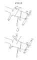
- Fig. 8 is a view showing a shape of the hoisting wire in a case where the second trolley is moved.
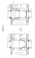
- Fig. 9 is a view showing a shape of the multi-stage in a case where the third trolley is moved
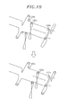
- Fig. 10 is a view showing a shape of the hoisting wire in a case where the third trolley is moved.
- the third trolley 132 is moved, the hoisting wire W out of the second trolley sheave blocks 122a is fixed.
- the third trolley 132 is moved in the lateral direction and a height of the spreader 140 is constantly maintained without a change of the length of the hoisting wire W in the third trolley sheave blocks 132a.
- Fig. 11 is a view showing a shape of the hoisting wire in a case where the spreader is moved.
- the hoisting wire W is wound or unwound by the wire driving drum 110a, and the spreader 140 is moved upward and downward according a winding or unwinding of the hoisting wire W.
- the crane with a multi-stage trolley may be provided on a floating body floated on the sea.
- the floating body may be a ship which is equipped with a self-power generating means and can be sailed, or a floating construction to be moored on the sea.
- the floating body can act as a mobile harbor which is floated on the sea and transfers a container between the container ships instead of a harbor of the land or together with a harbor of the land and stores temporarily the containers.
- the mobile harbor may include a platform having a space in which the container is loaded, a location determining device for acquiring information regarding the location of the platform, a mooring device for maintaining a connected state without colliding with the container carrier while a container is loaded or unloaded, and a balancing device for adjusting the platform such that the platform can be maintained in a vertical location correspondingly to a change in the weight based on the loading and unloading of the container.
- the spreader is moved in the longitudinal direction as well as the lateral direction on the trolley having the multi-stage trolley structure, and a vertical level of the spreader can be maintained or easily controlled.
Landscapes
- Engineering & Computer Science (AREA)
- Mechanical Engineering (AREA)
- Control And Safety Of Cranes (AREA)
- Carriers, Traveling Bodies, And Overhead Traveling Cranes (AREA)
Abstract
Description
- The present invention relates to a trolley and a crane for loading and unloading a cargo.
- A marine transportation using ships as a goods movement means to a remote area consumes less energy compared with other transportation and incurs a low transportation cost, so it takes a large portion of global trade.
- Recently, a marine transportation such as a container carrier uses a large ship in order to improve the efficiency of transportation, and the use of the large ship increases the volume of traffic of ships to secure economic efficiency of transportation. Thus, more harbors having mooring facilities for allowing a large ship to come alongside the pier and loading and unloading facilities are increasingly required.
- However, harbors allowing a large container ship to come alongside the pier are limited around the world, and construction of such a harbor incurs much cost due to dredging or the like for maintaining the depth of water in the harbor and requires a spacious area. In addition, the construction of a big harbor causes traffic congestion nearby or greatly affects the surrounding environment such as damage to a coastal environment, leaving a variety of restrictions to the construction of a big harbor.
- Thus, research into a mobile harbor allowing a large ship to anchor in the sea away from the land and ship and load cargo, rather than making a large ship to come alongside the pier in the harbor, is under way.
-
Fig. 1 is a schematic view showing that a container C handling operation with respect to a container carrier S is performed by a crane 1 installed in aship 50 serving as a mobile harbor. Here, a widthwise direction of a boom 10 (or a lengthwise direction of the ship 50) is defined as a lateral direction (X direction in the figure), and a lengthwise direction of the boom 10 (or a widthwise direction of the ship 50) is defined as a longitudinal direction (Y direction in the figure). - In general, the
crane 10 comprises aspreader 30 gripping a container C and moved in the vertical direction, atrolley 20 supporting thespreader 30 and moved in the longitudinal direction and theboom 10 guiding thetrolley 20 to enable the trolley to be moved. -
Fig. 2 is a view showing schematically a method for tying a hoist wire of a conventional crane. A spreader is moved in the vertical direction by using a hoist wire system provided on a boom B. The hoist wire system includes a wire drum B1 winding/unwinding a hoist wire W and a various kinds of sheave blocks B2, B3, T1 and S1 for changing a direction of the hoist wire W. A spreader is coupled to the sheave block S1. The hoist wire W is tied such that a vertical level of the spreader is not changed even though a trolley T is moved. - In the meantime, a pitching and a rolling of the ship on the sea are indispensably occurred due to a wind, wave or tidal current, and the like. Referring to
Fig. 1 , in the conventional crane 1, thetrolley 20 moved on thecrane boom 10 and thespreader 30 mounted to the trolley can be moved only the longitudinal direction. Accordingly, when a relative location between the crane 1 or theship 50 and the container ship S is not maintained due to a pitching and rolling of the ship, it is difficult to couple or decouple thespreader 30 with or from the container. To correct the above defect, the crane 1 itself or theship 50 itself should be moved, so that it is not easy to control the crane or the ship and power is excessively consumed. - The present invention provides a multi-stage trolley for a crane in which a spreader can be moved in the lateral direction as well as the longitudinal direction, and a vertical level of the spreader can be maintained constant in spite of the above movement.
- In accordance with an aspect of the present invention, there is provided a multi-stage trolley for a crane, comprising: a first trolley movable in a longitudinal direction along a boom of the crane; a second trolley movable in a lateral direction on the first trolley; a hoisting wire provided in the longitudinal direction along the boom; a spreader connected to the hoisting wire through the first trolley and the second trolley and supported by the hoisting wire, the spreader being movable in a vertical direction according to a movement of the hoisting wire; and a sheave block unit for changing a direction of the hoisting wire to maintain a vertical level of the spreader constant when the first trolley and/or the second trolley is moved.
- In accordance with another aspect of the present invention, there is provided a crane including the multi-stage trolley.
- The objects and features of the present invention will become apparent from the following description of embodiments given in conjunction with the accompanying drawings, in which:
-
Fig. 1 is a schematic view showing that a cargo handling operation with respect to a container carrier is performed by a crane installed in a ship; -
Fig. 2 is a view showing schematically a method for tying a hoist wire of a conventional crane; -
Fig. 3 is a view showing schematically a multi-stage trolley and a hoisting wire system employed in a crane according to one embodiment of the present invention; -
Fig. 4 is a view showing schematically a structure of the multi-stage trolley according to one embodiment of the present invention; -
Fig. 5 is a view showing schematically structure of the hoisting wire system with a sheave block unit according to one embodiment of the present invention; -
Fig. 6 is a view showing a shape of the multi-stage trolley in a case where a first trolley is moved along a boom; -
Fig. 7 is a view showing a shape of the multi-stage trolley in a case where a second trolley is moved; -
Fig. 8 is a view showing a shape of the hoisting wire in a case where the second trolley is moved; -
Fig. 9 is a view showing a shape of the multi-stage in a case where a third trolley is moved; -
Fig. 10 is a view showing a shape of the hoisting wire in a case where the third trolley is moved; and -
Fig. 11 is a view showing a shape of the hoisting wire in a case where a spreader is moved. - Hereinafter, embodiments of the present invention will be described in detail with reference to the accompanying drawings. Same reference numeral is given to the same or corresponding element, and a duplicated explanation thereon will be omitted.
- A multi-stage trolley for a crane according to one embodiment of the present invention is illustrated with reference to
Fig. 3 to Fig. 5 -
Fig. 3 is a view showing schematically a multi-stage trolley and a hoisting wire system employed in a crane according to one embodiment of the present invention,Fig. 4 is a view showing schematically a structure of the multi-stage trolley according to one embodiment of the present invention, andFig. 5 is a view showing schematically structure of the hoisting wire system with a sheave block unit according to one embodiment of the present invention. - The crane according to one embodiment of the present invention is provided with a hoisting wire system which have a multi-stage trolley structure by which a spreader can be moved in the lateral and/or the longitudinal directions and vertical level of the spreader can be maintained regardless of the above movement.
- The multi-stage trolley comprises a
first trolley 112, asecond trolley 122, athird trolley 132, aspreader 140, a hoisting wire W, awire driving drum 110a and a sheave block unit. - A structure and function of a multi-stage trolley is illustrated with reference to
Fig. 3 andFig. 4 . - The
first trolley 112 may be moved in the longitudinal direction along aboom 110. Thesecond trolley 122 may be moved on thefirst trolley 112 in the lateral direction. Thethird trolley 132 may be moved on thesecond trolley 122 in the longitudinal direction. By moving the first, second andthird trolleys spreader 140 can be also moved in both directions. - Although a longitudinal location of a cargo such as a container to be unloaded is changed, e. g., by a pitching and rolling of the ship, it is possible to operate rapidly and economically the crane by moving the
second trolley 122, without need to move the crane or the ship to which the crane is installed. - In order to move the
spreader 140 in the lateral direction for transporting the container, thefirst trolley 112 is utilized, and thethird trolley 132 can be moved in the lateral direction to correct a change of location caused by a pitching/rolling of the ship of the ship. Therefore, it is possible to operate rapidly and economically thespreader 140. - A structure and function of the hoisting wire system are described with reference to
Fig. 3 andFig. 5 . - The
spreader 140 is connected to the hoisting wire W through the first, second andthird trolleys spreader 140 can be moved in the vertical direction according to a movement of the hosting wire W. - The hosting wires W are provided at both lateral end portions of the
boom 110 and arranged in the longitudinal direction so that the hoisting wire may be connected tospreader 140. The hosting wire W is passed through boomend sheave blocks wire driving drum 110a to thespreader 140 through the first, second andthird trolleys - The
wire driving drum 110a winds or unwinds the hoisting wire W to adjust a vertical level of thespreader 140. A vertical movement of thespreader 140 is independently controlled by thewire driving drum 110a regardless of a movement of the trolley. - The sheave blocks change a direction of the hoisting wire to allow a vertical level of the
spreader 140 to be kept unchanged when thesecond trolley 122 is moved in the lateral direction. Also, the sheave blocks can compel the level of thespreader 140 to be unchanged when thethird trolley 132 is moved in the longitudinal direction. - A connection relation among the sheave blocks, the multi-stage trolley and the hoisting wire is illustrated in more detail with reference to
Fig. 4 andFig. 5 . - The sheave block unit may include direction changing
sheave blocks sheave blocks 112c, direction restoringsheave blocks 122a,spreader sheave blocks - Direction changing sheave blocks 112a and 112b change direction of the hoisting wire W provided in the longitudinal direction into the lateral direction. 2 or 4 pairs of direction changing
sheave blocks first trolley 112. Pairs of direction changingsheave blocks - Direction reversing
sheave blocks 112c change direction of the hoisting wire W by 180 degree, which is provided to thefirst trolley 112 in the lateral direction, by bending the hoisting wire into a U shape to connect the hoisting wire to thesecond trolley 122. 2 or 4 pairs of direction reversingsheave blocks 112c may be provided at lateral and longitudinal ends of thefirst trolley 112. Pairs of direction reversingsheave blocks 112c diagonally disposed are coupled to each other by the hoisting wire. - Direction restoring
sheave blocks 122a change direction of the hoisting wire W, which is provided to thesecond trolley 122 in the lateral direction, into the longitudinal direction to connect the hoisting wire to thethird trolley 132. 2 or 4 pairs of direction restoringsheave blocks 122a may be provided. Pairs of direction restoringsheave blocks 122a diagonally disposed are coupled to each other by the hoisting wire. -
Spreader sheave blocks 132a change direction of the hoisting wire W, which is provided to thethird trolley 132 in the longitudinal direction, into the vertical direction to connect the hoisting wire tospreader sheave blocks 140a provided on thespreader 140. 1 or 2 pairs of) thirdtrolley sheave blocks 132a may be provided. The sheave blocks 112a, 112b, 112c, 122a located on the diagonal position are connected each other through the hoisting wire W via thespreader sheave blocks 140a. - The
third trolley 132 may not be provided in another embodiment of the present invention. Although the above structure in which the third trolley is not provided is not shown in the drawings, instead of the thirdtrolley sheave blocks 132a, direction of the hoisting wire W may be changed into the vertical direction by sheave blocks provided on thesecond trolley 122, and so the hoisting wire can be connected to thespreader 140. - Below, an operating method of the multi-stage trolley and the crane according to one embodiment of the present invention is illustrated with reference to
Fig. 6 to Fig. 11 . -
Fig. 6 is a view showing a shape of the multi-stage trolley in a case where the first trolley is moved along the boom; - Even if the
first trolley 112 is moved along theboom 110, since a length of the hoisting wire W in thefirst trolley 112 is not changed, a vertical location of thespreader 140 is constantly maintained while thefirst trolley 112 is moved. -
Fig. 7 is a view showing a shape of the multi-stage trolley in a case where the second trolley is moved, andFig. 8 is a view showing a shape of the hoisting wire in a case where the second trolley is moved. - Since the direction reversing
sheave blocks 112c located on the diagonal position are connected each other through the hoisting wire W, even if thesecond trolley 122 is moved, the hoisting wire W out of the firsttrolley sheave blocks 112c is fixed. Thesecond trolley 122 is moved in the longitudinal direction and a height of thespreader 140 is constantly maintained without a change of the length of the hoisting wire W in the secondtrolley sheave blocks 122a. -
Fig. 9 is a view showing a shape of the multi-stage in a case where the third trolley is moved, andFig. 10 is a view showing a shape of the hoisting wire in a case where the third trolley is moved. - Although the
third trolley 132 is moved, the hoisting wire W out of the secondtrolley sheave blocks 122a is fixed. Thethird trolley 132 is moved in the lateral direction and a height of thespreader 140 is constantly maintained without a change of the length of the hoisting wire W in the thirdtrolley sheave blocks 132a. -
Fig. 11 is a view showing a shape of the hoisting wire in a case where the spreader is moved. - The hoisting wire W is wound or unwound by the
wire driving drum 110a, and thespreader 140 is moved upward and downward according a winding or unwinding of the hoisting wire W. - The crane with a multi-stage trolley according to one embodiment of the present invention may be provided on a floating body floated on the sea.
- The floating body may be a ship which is equipped with a self-power generating means and can be sailed, or a floating construction to be moored on the sea. The floating body can act as a mobile harbor which is floated on the sea and transfers a container between the container ships instead of a harbor of the land or together with a harbor of the land and stores temporarily the containers.
- The mobile harbor, may include a platform having a space in which the container is loaded, a location determining device for acquiring information regarding the location of the platform, a mooring device for maintaining a connected state without colliding with the container carrier while a container is loaded or unloaded, and a balancing device for adjusting the platform such that the platform can be maintained in a vertical location correspondingly to a change in the weight based on the loading and unloading of the container.
- According to the embodiment of the present invention, the spreader is moved in the longitudinal direction as well as the lateral direction on the trolley having the multi-stage trolley structure, and a vertical level of the spreader can be maintained or easily controlled.
- While the invention has been shown and described with respect to the preferred embodiments, it will be understood by those skilled in the art that various changes and modifications may be made without departing from the scope of the invention as defined in the following claims.
Claims (10)
- A multi-stage trolley for a crane, comprising:a first trolley movable in a longitudinal direction along a boom of the crane;a second trolley movable in a lateral direction on the first trolley;a hoisting wire provided in the longitudinal direction along the boom;a spreader connected to the hoisting wire through the first trolley and the second trolley and supported by the hoisting wire, the spreader being movable in a vertical direction according to a movement of the hoisting wire; anda sheave block unit for changing a direction of the hoisting wire to maintain a vertical level of the spreader constant when the first trolley and/or the second trolley is moved.
- The multi-stage trolley of claim 1, wherein the sheave block unit includes direction changing sheave blocks,
at least one thereof changing a direction of the hoisting wire provided thereto in the longitudinal direction into the lateral direction. - The multi-stage trolley of claim 2, wherein the direction changing sheave blocks include pairs of direction changing sheave blocks diagonally disposed at the first trolley, and
at least one pair of the direction changing sheave blocks are coupled to each other by the hoisting wire. - The multi-stage trolley of claim 2 or 3, wherein at least one of the direction changing sheave blocks changes the direction of the hoisting wire provided thereto in the longitudinal direction into the vertical direction and then into the lateral direction.
- The multi-stage trolley of one of claims 1 to 4, wherein the sheave block unit includes direction reversing sheave blocks,
at least one thereof changing a direction of the hoisting wire provided thereto in the lateral direction by 180 degree to connect same to the second trolley. - The multi-stage trolley of claim 5, wherein the direction reversing sheave blocks include pairs of direction reversing sheave blocks diagonally disposed at the first trolley, and
at least one pair of the direction reversing sheave blocks are coupled to each other by the hoisting wire. - The multi-stage trolley of claim 6, wherein the pairs of the direction reversing sheave blocks are disposed at lateral ends of the first trolley.
- The multi-stage trolley of one of claims 1 to 7, further comprising a third trolley movable in the longitudinal direction on the second trolley,
wherein the sheave block unit maintains constant the vertical level of the spreader when the third trolley is moved. - The multi-stage trolley of claim 8, wherein the sheave block unit includes direction restoring sheave blocks provided on the second trolley,
at least one thereof changing a direction of the hoisting wire provided thereto in the lateral direction into the longitudinal direction to connect same to the third trolley. - A crane comprising the multi-stage trolley of one of claims 1 to 9.
Applications Claiming Priority (1)
| Application Number | Priority Date | Filing Date | Title |
|---|---|---|---|
| KR1020100032270A KR101112156B1 (en) | 2010-04-08 | 2010-04-08 | Container crane with multi-stage trolley |
Publications (2)
| Publication Number | Publication Date |
|---|---|
| EP2374748A1 true EP2374748A1 (en) | 2011-10-12 |
| EP2374748B1 EP2374748B1 (en) | 2012-11-21 |
Family
ID=44212204
Family Applications (1)
| Application Number | Title | Priority Date | Filing Date |
|---|---|---|---|
| EP10194823A Not-in-force EP2374748B1 (en) | 2010-04-08 | 2010-12-14 | Multi-stage trolley for a crane and a crane therewith |
Country Status (5)
| Country | Link |
|---|---|
| US (1) | US8708172B2 (en) |
| EP (1) | EP2374748B1 (en) |
| KR (1) | KR101112156B1 (en) |
| CN (1) | CN102211740A (en) |
| WO (1) | WO2011126201A1 (en) |
Families Citing this family (12)
| Publication number | Priority date | Publication date | Assignee | Title |
|---|---|---|---|---|
| FI124474B (en) * | 2013-03-01 | 2014-09-15 | Konecranes Oyj | Lift repair arrangement in a hoist lift truck |
| US8905702B1 (en) * | 2013-03-05 | 2014-12-09 | Inland Pipe Rehabilitation, Llc | Cable-driven trailer loading system for liner |
| WO2018179369A1 (en) * | 2017-03-31 | 2018-10-04 | 平田機工株式会社 | Conveying device |
| KR102220458B1 (en) * | 2019-04-01 | 2021-02-26 | (주)엔키아 | Wire diagnostics apparatus for lifting device |
| CN110407087B (en) * | 2019-08-26 | 2024-12-17 | 上海振华重工(集团)股份有限公司 | Lengthening device and lengthening method for girder of shore container crane |
| KR102385064B1 (en) | 2020-07-16 | 2022-04-11 | 현대삼호중공업 주식회사 | Hoist device for crane |
| KR102437147B1 (en) | 2020-07-24 | 2022-08-26 | 현대인프라솔루션 주식회사 | Container crane |
| CN112061985A (en) * | 2020-09-30 | 2020-12-11 | 上海振华重工(集团)股份有限公司 | A double drum anti-sway gantry trolley system |
| KR20230144433A (en) | 2022-04-07 | 2023-10-16 | 노갑문 | A smart and energy-saving container Crane system |
| KR20230158811A (en) | 2022-05-12 | 2023-11-21 | 남해호이스트 주식회사 | Hoist device for crane |
| US20240417985A1 (en) * | 2023-06-19 | 2024-12-19 | Obshchestvo s ogranichennoi otvetstvennostiu «Diginavis» | Device and method for erecting structures using building blocks |
| US12398532B2 (en) * | 2024-01-19 | 2025-08-26 | Wing Marine Llc | Marine vessels and methods of using same |
Citations (4)
| Publication number | Priority date | Publication date | Assignee | Title |
|---|---|---|---|---|
| US20080213073A1 (en) * | 2007-03-01 | 2008-09-04 | Tesseract International, Inc. | Port storage and distribution system for international shipping containers |
| WO2011034260A1 (en) * | 2009-09-16 | 2011-03-24 | 한국과학기술원 | Dual boom structure, dual boom crane and ship mounted with same |
| WO2011043516A1 (en) * | 2009-10-08 | 2011-04-14 | 한국과학기술원 | Dual boom structure, dual boom crane and ship mounted with the same |
| WO2011049268A1 (en) * | 2009-10-22 | 2011-04-28 | 한국과학기술원 | Dual guide crane, shipping furnished with the same and a container-landing method |
Family Cites Families (28)
| Publication number | Priority date | Publication date | Assignee | Title |
|---|---|---|---|---|
| US3081884A (en) * | 1961-06-09 | 1963-03-19 | Manning Maxwell & Moore Inc | Crane with anti-sway mechanism |
| US3207329A (en) * | 1962-12-03 | 1965-09-21 | Lake Shore Inc | Cargo handling apparatus |
| GB1162878A (en) * | 1967-06-09 | 1969-08-27 | John Stevenson Thomson | Improvements relating to Cranes for Handling Containers |
| US3536351A (en) * | 1967-11-13 | 1970-10-27 | Fruehauf Corp | Apparatus for simultaneously lifting and spacing cargo containers |
| US3671069A (en) * | 1970-07-15 | 1972-06-20 | Fruehaul Corp | Cargo container lifting and spacing apparatus |
| US3945503A (en) * | 1970-10-02 | 1976-03-23 | Fruehauf Corporation | Crane with a variable center rope suspension system |
| US3899083A (en) * | 1972-03-24 | 1975-08-12 | Krupp Gmbh | Device ofr damping pendulum movements |
| US3779395A (en) * | 1972-11-15 | 1973-12-18 | Heyl & Patterson | Clamshell bucket unloader with rope operated trolley |
| AU471953B2 (en) * | 1972-12-29 | 1976-05-06 | Ishikawajima-Harima Jukogyo K.K. | Device for preventing the swaying ofthe suspending means ina crane |
| US3887080A (en) * | 1973-06-29 | 1975-06-03 | Ray Wilson | Crane structure |
| US3944272A (en) * | 1974-08-12 | 1976-03-16 | Midland-Ross Corporation | Cargo container spreader with articulated structure for skewing and tilting |
| NL7614540A (en) * | 1976-12-29 | 1978-07-03 | Figee Maschf | CRANE WITH TOP SYSTEM SUITABLE FOR TREATING BOTH PARTS AND CONTAINERS. |
| JPS6038318B2 (en) * | 1977-09-20 | 1985-08-31 | 石川島播磨重工業株式会社 | Quay cargo handling crane |
| FR2443996A1 (en) * | 1978-12-15 | 1980-07-11 | Potain Sa | LIFTING EQUIPMENT SUCH AS A CRANE OR GANTRY FOR THE HANDLING OF CONTAINERS |
| US5186342A (en) * | 1990-11-07 | 1993-02-16 | Paceco Corp. | Integrated passive sway arrest system for cargo container handling cranes |
| US5538382A (en) * | 1994-06-03 | 1996-07-23 | Paceco Corp. | Variable level lifting platform for a cargo container handling crane |
| US5713477A (en) * | 1995-10-12 | 1998-02-03 | Wallace, Jr.; Walter J. | Method and apparatus for controlling and operating a container crane or other similar cranes |
| CA2234489A1 (en) * | 1997-04-11 | 1998-10-11 | Dave Staats | Logging carriage apparatus |
| KR19980085896A (en) * | 1997-05-30 | 1998-12-05 | 김정국 | Anti-shake device of container crane |
| FI104816B (en) * | 1997-09-24 | 2000-04-14 | Kci Kone Cranes Int Oy | Arrangement for damping the overload and thrust movement energy directed against the lifting tackle of a lifting crane |
| TW542227U (en) * | 1997-12-03 | 2003-07-11 | Mitsubishi Heavy Ind Ltd | Crane apparatus |
| KR100255882B1 (en) * | 1998-06-01 | 2000-05-01 | 추호석 | Sheave operating system to reduce the by hydro cylinder control |
| US6439407B1 (en) * | 1998-07-13 | 2002-08-27 | The United States Of America As Represented By The Secretary Of Commerce | System for stabilizing and controlling a hoisted load |
| US6250486B1 (en) * | 1999-09-13 | 2001-06-26 | Masamitsu Enoki | Integrated balanced wire rope reeving system for cargo container handling cranes |
| KR100567466B1 (en) * | 1999-12-22 | 2006-04-03 | 현대삼호중공업 주식회사 | Container shake control |
| CN1255314C (en) * | 2003-02-12 | 2006-05-10 | 上海振华港口机械(集团)股份有限公司 | Deviation correcting technology for a steel cable winding type sling |
| KR100649728B1 (en) * | 2006-02-10 | 2006-11-28 | 두산중공업 주식회사 | Anti sway device in trolley |
| CN2918355Y (en) * | 2006-07-14 | 2007-07-04 | 中国华电工程(集团)有限公司 | Eight-rope shaking-proof lifting mechanism of container crane |
-
2010
- 2010-04-08 KR KR1020100032270A patent/KR101112156B1/en not_active Expired - Fee Related
- 2010-12-14 EP EP10194823A patent/EP2374748B1/en not_active Not-in-force
- 2010-12-16 WO PCT/KR2010/008997 patent/WO2011126201A1/en not_active Ceased
- 2010-12-16 US US12/969,775 patent/US8708172B2/en not_active Expired - Fee Related
- 2010-12-31 CN CN2010106201561A patent/CN102211740A/en active Pending
Patent Citations (4)
| Publication number | Priority date | Publication date | Assignee | Title |
|---|---|---|---|---|
| US20080213073A1 (en) * | 2007-03-01 | 2008-09-04 | Tesseract International, Inc. | Port storage and distribution system for international shipping containers |
| WO2011034260A1 (en) * | 2009-09-16 | 2011-03-24 | 한국과학기술원 | Dual boom structure, dual boom crane and ship mounted with same |
| WO2011043516A1 (en) * | 2009-10-08 | 2011-04-14 | 한국과학기술원 | Dual boom structure, dual boom crane and ship mounted with the same |
| WO2011049268A1 (en) * | 2009-10-22 | 2011-04-28 | 한국과학기술원 | Dual guide crane, shipping furnished with the same and a container-landing method |
Also Published As
| Publication number | Publication date |
|---|---|
| US20110247991A1 (en) | 2011-10-13 |
| WO2011126201A1 (en) | 2011-10-13 |
| KR20110112987A (en) | 2011-10-14 |
| CN102211740A (en) | 2011-10-12 |
| EP2374748B1 (en) | 2012-11-21 |
| US8708172B2 (en) | 2014-04-29 |
| KR101112156B1 (en) | 2012-02-22 |
Similar Documents
| Publication | Publication Date | Title |
|---|---|---|
| EP2374748B1 (en) | Multi-stage trolley for a crane and a crane therewith | |
| CN103492294B (en) | The combination of loading and unloading crane equipment and loading and unloading crane equipment that two or more are adjacent | |
| US8118534B2 (en) | Container cargo transfer system | |
| Bartošek et al. | Quay cranes in container terminals | |
| EP2927110B1 (en) | Vessel comprising cargo transloading system | |
| US6932326B1 (en) | Method for lifting and transporting a heavy load using a fly-jib | |
| WO2009138043A1 (en) | Ship-to-shore goods loading/unloading machine with supports on ship and quay | |
| US3945508A (en) | Devices for transferring heavy loads at sea | |
| CN203461562U (en) | Transferring platform | |
| US6964552B1 (en) | Method for lifting and transporting a heavy load using a deep water deployment system | |
| KR101511048B1 (en) | Jib crane | |
| KR101166718B1 (en) | Stabilized Container Crane With Improved Legs | |
| KR100827462B1 (en) | Removable floating quay | |
| KR101166717B1 (en) | Mobile Harbor With Container Crane | |
| KR101383860B1 (en) | Trolly driving apparatus of crane system for mobile harbor | |
| KR20240022037A (en) | Floating jig and method for installing support structure of offshore wind power generator using the same | |
| KR20110079443A (en) | Container Unloading Method Using Mobile Harbor | |
| KR101112158B1 (en) | Mobile portal crane and vessel with the crane | |
| KR20110073185A (en) | Container Cranes | |
| KR101125044B1 (en) | Container Crane With Downward Housed Boom | |
| KR20110124960A (en) | Offshore Float with Container Crane | |
| Jordan | Future-Proof Your Crane | |
| CN214648893U (en) | Floating base for logistics support | |
| KR20110069441A (en) | Multistage crane system | |
| KR20150000890U (en) | Carrier equipment for cargo-working of pier mooring ship |
Legal Events
| Date | Code | Title | Description |
|---|---|---|---|
| PUAI | Public reference made under article 153(3) epc to a published international application that has entered the european phase |
Free format text: ORIGINAL CODE: 0009012 |
|
| AK | Designated contracting states |
Kind code of ref document: A1 Designated state(s): AL AT BE BG CH CY CZ DE DK EE ES FI FR GB GR HR HU IE IS IT LI LT LU LV MC MK MT NL NO PL PT RO RS SE SI SK SM TR |
|
| AX | Request for extension of the european patent |
Extension state: BA ME |
|
| 17P | Request for examination filed |
Effective date: 20120412 |
|
| RIC1 | Information provided on ipc code assigned before grant |
Ipc: B66C 19/00 20060101AFI20120523BHEP |
|
| GRAP | Despatch of communication of intention to grant a patent |
Free format text: ORIGINAL CODE: EPIDOSNIGR1 |
|
| GRAS | Grant fee paid |
Free format text: ORIGINAL CODE: EPIDOSNIGR3 |
|
| GRAA | (expected) grant |
Free format text: ORIGINAL CODE: 0009210 |
|
| AK | Designated contracting states |
Kind code of ref document: B1 Designated state(s): AL AT BE BG CH CY CZ DE DK EE ES FI FR GB GR HR HU IE IS IT LI LT LU LV MC MK MT NL NO PL PT RO RS SE SI SK SM TR |
|
| RAP1 | Party data changed (applicant data changed or rights of an application transferred) |
Owner name: KOREA ADVANCED INSTITUTE OF SCIENCE AND TECHNOLOGY |
|
| REG | Reference to a national code |
Ref country code: GB Ref legal event code: FG4D |
|
| REG | Reference to a national code |
Ref country code: CH Ref legal event code: EP |
|
| REG | Reference to a national code |
Ref country code: AT Ref legal event code: REF Ref document number: 584971 Country of ref document: AT Kind code of ref document: T Effective date: 20121215 |
|
| REG | Reference to a national code |
Ref country code: IE Ref legal event code: FG4D |
|
| REG | Reference to a national code |
Ref country code: DE Ref legal event code: R096 Ref document number: 602010003713 Country of ref document: DE Effective date: 20130117 |
|
| REG | Reference to a national code |
Ref country code: NO Ref legal event code: T2 Effective date: 20121121 |
|
| REG | Reference to a national code |
Ref country code: NL Ref legal event code: VDEP Effective date: 20121121 |
|
| REG | Reference to a national code |
Ref country code: AT Ref legal event code: MK05 Ref document number: 584971 Country of ref document: AT Kind code of ref document: T Effective date: 20121121 |
|
| REG | Reference to a national code |
Ref country code: LT Ref legal event code: MG4D |
|
| PG25 | Lapsed in a contracting state [announced via postgrant information from national office to epo] |
Ref country code: FI Free format text: LAPSE BECAUSE OF FAILURE TO SUBMIT A TRANSLATION OF THE DESCRIPTION OR TO PAY THE FEE WITHIN THE PRESCRIBED TIME-LIMIT Effective date: 20121121 Ref country code: SE Free format text: LAPSE BECAUSE OF FAILURE TO SUBMIT A TRANSLATION OF THE DESCRIPTION OR TO PAY THE FEE WITHIN THE PRESCRIBED TIME-LIMIT Effective date: 20121121 Ref country code: ES Free format text: LAPSE BECAUSE OF FAILURE TO SUBMIT A TRANSLATION OF THE DESCRIPTION OR TO PAY THE FEE WITHIN THE PRESCRIBED TIME-LIMIT Effective date: 20130304 Ref country code: LT Free format text: LAPSE BECAUSE OF FAILURE TO SUBMIT A TRANSLATION OF THE DESCRIPTION OR TO PAY THE FEE WITHIN THE PRESCRIBED TIME-LIMIT Effective date: 20121121 |
|
| PG25 | Lapsed in a contracting state [announced via postgrant information from national office to epo] |
Ref country code: BE Free format text: LAPSE BECAUSE OF FAILURE TO SUBMIT A TRANSLATION OF THE DESCRIPTION OR TO PAY THE FEE WITHIN THE PRESCRIBED TIME-LIMIT Effective date: 20121121 Ref country code: PT Free format text: LAPSE BECAUSE OF FAILURE TO SUBMIT A TRANSLATION OF THE DESCRIPTION OR TO PAY THE FEE WITHIN THE PRESCRIBED TIME-LIMIT Effective date: 20130321 Ref country code: GR Free format text: LAPSE BECAUSE OF FAILURE TO SUBMIT A TRANSLATION OF THE DESCRIPTION OR TO PAY THE FEE WITHIN THE PRESCRIBED TIME-LIMIT Effective date: 20130222 Ref country code: SI Free format text: LAPSE BECAUSE OF FAILURE TO SUBMIT A TRANSLATION OF THE DESCRIPTION OR TO PAY THE FEE WITHIN THE PRESCRIBED TIME-LIMIT Effective date: 20121121 Ref country code: PL Free format text: LAPSE BECAUSE OF FAILURE TO SUBMIT A TRANSLATION OF THE DESCRIPTION OR TO PAY THE FEE WITHIN THE PRESCRIBED TIME-LIMIT Effective date: 20121121 Ref country code: LV Free format text: LAPSE BECAUSE OF FAILURE TO SUBMIT A TRANSLATION OF THE DESCRIPTION OR TO PAY THE FEE WITHIN THE PRESCRIBED TIME-LIMIT Effective date: 20121121 |
|
| PG25 | Lapsed in a contracting state [announced via postgrant information from national office to epo] |
Ref country code: AT Free format text: LAPSE BECAUSE OF FAILURE TO SUBMIT A TRANSLATION OF THE DESCRIPTION OR TO PAY THE FEE WITHIN THE PRESCRIBED TIME-LIMIT Effective date: 20121121 |
|
| PG25 | Lapsed in a contracting state [announced via postgrant information from national office to epo] |
Ref country code: EE Free format text: LAPSE BECAUSE OF FAILURE TO SUBMIT A TRANSLATION OF THE DESCRIPTION OR TO PAY THE FEE WITHIN THE PRESCRIBED TIME-LIMIT Effective date: 20121121 Ref country code: CZ Free format text: LAPSE BECAUSE OF FAILURE TO SUBMIT A TRANSLATION OF THE DESCRIPTION OR TO PAY THE FEE WITHIN THE PRESCRIBED TIME-LIMIT Effective date: 20121121 Ref country code: RS Free format text: LAPSE BECAUSE OF FAILURE TO SUBMIT A TRANSLATION OF THE DESCRIPTION OR TO PAY THE FEE WITHIN THE PRESCRIBED TIME-LIMIT Effective date: 20121121 Ref country code: DK Free format text: LAPSE BECAUSE OF FAILURE TO SUBMIT A TRANSLATION OF THE DESCRIPTION OR TO PAY THE FEE WITHIN THE PRESCRIBED TIME-LIMIT Effective date: 20121121 Ref country code: MC Free format text: LAPSE BECAUSE OF NON-PAYMENT OF DUE FEES Effective date: 20121231 Ref country code: SK Free format text: LAPSE BECAUSE OF FAILURE TO SUBMIT A TRANSLATION OF THE DESCRIPTION OR TO PAY THE FEE WITHIN THE PRESCRIBED TIME-LIMIT Effective date: 20121121 Ref country code: BG Free format text: LAPSE BECAUSE OF FAILURE TO SUBMIT A TRANSLATION OF THE DESCRIPTION OR TO PAY THE FEE WITHIN THE PRESCRIBED TIME-LIMIT Effective date: 20130221 |
|
| PG25 | Lapsed in a contracting state [announced via postgrant information from national office to epo] |
Ref country code: NL Free format text: LAPSE BECAUSE OF FAILURE TO SUBMIT A TRANSLATION OF THE DESCRIPTION OR TO PAY THE FEE WITHIN THE PRESCRIBED TIME-LIMIT Effective date: 20121121 Ref country code: RO Free format text: LAPSE BECAUSE OF FAILURE TO SUBMIT A TRANSLATION OF THE DESCRIPTION OR TO PAY THE FEE WITHIN THE PRESCRIBED TIME-LIMIT Effective date: 20121121 Ref country code: IT Free format text: LAPSE BECAUSE OF FAILURE TO SUBMIT A TRANSLATION OF THE DESCRIPTION OR TO PAY THE FEE WITHIN THE PRESCRIBED TIME-LIMIT Effective date: 20121121 |
|
| REG | Reference to a national code |
Ref country code: IE Ref legal event code: MM4A |
|
| PLBE | No opposition filed within time limit |
Free format text: ORIGINAL CODE: 0009261 |
|
| REG | Reference to a national code |
Ref country code: FR Ref legal event code: ST Effective date: 20130830 |
|
| STAA | Information on the status of an ep patent application or granted ep patent |
Free format text: STATUS: NO OPPOSITION FILED WITHIN TIME LIMIT |
|
| 26N | No opposition filed |
Effective date: 20130822 |
|
| PG25 | Lapsed in a contracting state [announced via postgrant information from national office to epo] |
Ref country code: IE Free format text: LAPSE BECAUSE OF NON-PAYMENT OF DUE FEES Effective date: 20121214 Ref country code: DE Free format text: LAPSE BECAUSE OF NON-PAYMENT OF DUE FEES Effective date: 20130702 |
|
| REG | Reference to a national code |
Ref country code: DE Ref legal event code: R119 Ref document number: 602010003713 Country of ref document: DE Effective date: 20130702 |
|
| PG25 | Lapsed in a contracting state [announced via postgrant information from national office to epo] |
Ref country code: MT Free format text: LAPSE BECAUSE OF FAILURE TO SUBMIT A TRANSLATION OF THE DESCRIPTION OR TO PAY THE FEE WITHIN THE PRESCRIBED TIME-LIMIT Effective date: 20121121 Ref country code: AL Free format text: LAPSE BECAUSE OF FAILURE TO SUBMIT A TRANSLATION OF THE DESCRIPTION OR TO PAY THE FEE WITHIN THE PRESCRIBED TIME-LIMIT Effective date: 20121121 Ref country code: FR Free format text: LAPSE BECAUSE OF NON-PAYMENT OF DUE FEES Effective date: 20130121 |
|
| PG25 | Lapsed in a contracting state [announced via postgrant information from national office to epo] |
Ref country code: HR Free format text: LAPSE BECAUSE OF FAILURE TO SUBMIT A TRANSLATION OF THE DESCRIPTION OR TO PAY THE FEE WITHIN THE PRESCRIBED TIME-LIMIT Effective date: 20130731 |
|
| PG25 | Lapsed in a contracting state [announced via postgrant information from national office to epo] |
Ref country code: TR Free format text: LAPSE BECAUSE OF FAILURE TO SUBMIT A TRANSLATION OF THE DESCRIPTION OR TO PAY THE FEE WITHIN THE PRESCRIBED TIME-LIMIT Effective date: 20121121 |
|
| PG25 | Lapsed in a contracting state [announced via postgrant information from national office to epo] |
Ref country code: CY Free format text: LAPSE BECAUSE OF FAILURE TO SUBMIT A TRANSLATION OF THE DESCRIPTION OR TO PAY THE FEE WITHIN THE PRESCRIBED TIME-LIMIT Effective date: 20121121 Ref country code: LU Free format text: LAPSE BECAUSE OF NON-PAYMENT OF DUE FEES Effective date: 20121214 Ref country code: SM Free format text: LAPSE BECAUSE OF FAILURE TO SUBMIT A TRANSLATION OF THE DESCRIPTION OR TO PAY THE FEE WITHIN THE PRESCRIBED TIME-LIMIT Effective date: 20121121 |
|
| PG25 | Lapsed in a contracting state [announced via postgrant information from national office to epo] |
Ref country code: HU Free format text: LAPSE BECAUSE OF FAILURE TO SUBMIT A TRANSLATION OF THE DESCRIPTION OR TO PAY THE FEE WITHIN THE PRESCRIBED TIME-LIMIT Effective date: 20101214 |
|
| PG25 | Lapsed in a contracting state [announced via postgrant information from national office to epo] |
Ref country code: MK Free format text: LAPSE BECAUSE OF FAILURE TO SUBMIT A TRANSLATION OF THE DESCRIPTION OR TO PAY THE FEE WITHIN THE PRESCRIBED TIME-LIMIT Effective date: 20121121 |
|
| REG | Reference to a national code |
Ref country code: CH Ref legal event code: PL |
|
| GBPC | Gb: european patent ceased through non-payment of renewal fee |
Effective date: 20141214 |
|
| PG25 | Lapsed in a contracting state [announced via postgrant information from national office to epo] |
Ref country code: LI Free format text: LAPSE BECAUSE OF NON-PAYMENT OF DUE FEES Effective date: 20141231 Ref country code: GB Free format text: LAPSE BECAUSE OF NON-PAYMENT OF DUE FEES Effective date: 20141214 Ref country code: CH Free format text: LAPSE BECAUSE OF NON-PAYMENT OF DUE FEES Effective date: 20141231 |
|
| PG25 | Lapsed in a contracting state [announced via postgrant information from national office to epo] |
Ref country code: IS Free format text: LAPSE BECAUSE OF FAILURE TO SUBMIT A TRANSLATION OF THE DESCRIPTION OR TO PAY THE FEE WITHIN THE PRESCRIBED TIME-LIMIT Effective date: 20121121 |
|
| PGFP | Annual fee paid to national office [announced via postgrant information from national office to epo] |
Ref country code: NO Payment date: 20181120 Year of fee payment: 9 |
|
| REG | Reference to a national code |
Ref country code: NO Ref legal event code: MMEP |
|
| PG25 | Lapsed in a contracting state [announced via postgrant information from national office to epo] |
Ref country code: NO Free format text: LAPSE BECAUSE OF NON-PAYMENT OF DUE FEES Effective date: 20191231 |