EP2374579B1 - Meissel für Holz und Klinge für Meissel - Google Patents
Meissel für Holz und Klinge für Meissel Download PDFInfo
- Publication number
- EP2374579B1 EP2374579B1 EP10003752A EP10003752A EP2374579B1 EP 2374579 B1 EP2374579 B1 EP 2374579B1 EP 10003752 A EP10003752 A EP 10003752A EP 10003752 A EP10003752 A EP 10003752A EP 2374579 B1 EP2374579 B1 EP 2374579B1
- Authority
- EP
- European Patent Office
- Prior art keywords
- removable blade
- blade
- tool
- chisel
- profiled part
- Prior art date
- Legal status (The legal status is an assumption and is not a legal conclusion. Google has not performed a legal analysis and makes no representation as to the accuracy of the status listed.)
- Active
Links
- 239000002023 wood Substances 0.000 title claims description 24
- 239000000463 material Substances 0.000 claims description 2
- 230000000903 blocking effect Effects 0.000 description 27
- 230000000717 retained effect Effects 0.000 description 4
- 230000002787 reinforcement Effects 0.000 description 2
- 230000001419 dependent effect Effects 0.000 description 1
- 238000006073 displacement reaction Methods 0.000 description 1
- 230000014759 maintenance of location Effects 0.000 description 1
Images


Classifications
-
- B—PERFORMING OPERATIONS; TRANSPORTING
- B25—HAND TOOLS; PORTABLE POWER-DRIVEN TOOLS; MANIPULATORS
- B25D—PERCUSSIVE TOOLS
- B25D3/00—Hand chisels
-
- B—PERFORMING OPERATIONS; TRANSPORTING
- B23—MACHINE TOOLS; METAL-WORKING NOT OTHERWISE PROVIDED FOR
- B23B—TURNING; BORING
- B23B31/00—Chucks; Expansion mandrels; Adaptations thereof for remote control
- B23B31/02—Chucks
- B23B31/10—Chucks characterised by the retaining or gripping devices or their immediate operating means
- B23B31/117—Retention by friction only, e.g. using springs, resilient sleeves, tapers
-
- B—PERFORMING OPERATIONS; TRANSPORTING
- B25—HAND TOOLS; PORTABLE POWER-DRIVEN TOOLS; MANIPULATORS
- B25G—HANDLES FOR HAND IMPLEMENTS
- B25G3/00—Attaching handles to the implements
- B25G3/02—Socket, tang, or like fixings
- B25G3/12—Locking and securing devices
-
- B—PERFORMING OPERATIONS; TRANSPORTING
- B25—HAND TOOLS; PORTABLE POWER-DRIVEN TOOLS; MANIPULATORS
- B25G—HANDLES FOR HAND IMPLEMENTS
- B25G3/00—Attaching handles to the implements
- B25G3/02—Socket, tang, or like fixings
- B25G3/12—Locking and securing devices
- B25G3/24—Locking and securing devices comprising clamping or contracting means acting transversely on the handle or socket
Definitions
- the present invention relates to a tool with a removable blade, including a wood chisel and a blade for such a tool.
- the object of the present invention is to provide a tool, including a wood chisel, whose blade is removable, which allows a quick and easy change of the blade, without the use of an auxiliary tool for mounting or dismounting the blade , while ensuring a secure hold of the blade once it is attached to said tool.
- the present invention also aims to provide a removable blade for equipping a tool, including a wood chisel.
- the present invention relates to a tool, particularly a wood chisel, comprising a first section, a second profile and a removable blade characterized in that the second section is driven in the first so that the removable blade can be inserted between said first and second sections and to be held there by friction.
- the present invention also relates to a removable blade for equipping a tool including a chisel according to the invention.
- the figure 6a illustrates the removable blade of a chisel according to the second embodiment of the invention.
- the figure 6b is a profile view of the blade shown in the figure 6a .
- the figure 7 illustrates a chisel according to the second embodiment of the invention wherein the slider is in a first closed position.
- the figure 8 illustrates a chisel according to the second embodiment of the invention wherein the slider is in a second open position.
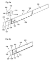
- the tool with a removable blade according to the invention is a wood chisel.
- Said wood chisel comprises a first section 100 having the shape of a substantially rectangular plate whose edges 101 are bent as shown in the enlargement 102 of the figure 1 at.
- the wood chisel according to the invention also comprises a second section 103 having the form of a substantially rectangular plate whose edges 104 are bent as shown in the enlargement 102 of the figure 1 at.
- the second section 103 is shaped so that it can be inserted into the first profile 100 and its length is substantially equal to that of the first profile 100.
- the chisel according to the invention also comprises a core 105 having the shape of a substantially rectangular plate and intended to be inserted between the first and second profiles 100, 103.
- the core 105 serves as a chisel reinforcement to wood according to the invention thus improving the rigidity of the tool.
- the chisel according to the invention further comprises a removable blade 106 formed of a cutting plate 107 secured to a fixing plate 108.
- the cutting plate 107 has at its free end a cutting edge 109.
- the size and the shape of the attachment plate 108 is such that it can be force-fitted between the first and second profiles, thus fixing the removable blade to the wood chisel according to the invention.
- the size of the cutting deck and the angle of the cutting edge may vary depending on the type of blade.
- the core is substantially shorter than the first and second sections 100, 103 as illustrated in FIG. figure 1b , to allow the embedding of the attachment plate 108 of the removable blade 106 between the first and second profiles 100, 103.
- the first and second profiles each comprise, at their end receiving the removable blade, a first oblong opening 110.
- the removable blade 106 comprises in turn on the attachment plate 108 a hole 111.
- the first oblong openings 110 and the hole 111 are such that when the detachable blade 106 is inserted between the first and second profiles 100, 103 the hole 111 is visible through the oblong openings 110 as shown in FIG. figure 1 b. This allows in particular to easily remove the removable blade 106 of the wood chisel.
- the tool with removable blade according to the invention is also a wood chisel.
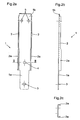
- said chisel comprises a first section 1 illustrated in FIG. figure 2a and having the shape of a substantially rectangular plate.
- a first end 1a of the first section 1 is shaped to fit and be retained in a handle (not shown) of the chisel.
- the first section 1 has curved edges 2 along its length except at its first end 1a.
- the first section 1 further comprises different openings whose role will be detailed later.
- a first hole 3 is made in the first section 1 at its first end 1a.
- the first section 1 further comprises a second hole 4 located between its curved edges 2.
- the first section 1 further comprises two positioning holes 5 at its second end 1b.
- the chisel according to the second embodiment of the invention comprises a core 6 illustrated in FIG. figure 3a and having the shape of a substantially rectangular plate.
- the core 6 is shaped so as to be slidable between the curved edges 2 of the first profile 1.
- the core 6 also has an end 6a shaped in size and shape to the first end 1a of the first section 1 and intended to be inserted and retained in the handle of the chisel.
- the core 6 serves as a reinforcement to the chisel according to the invention.
- the core 6 comprises at its end 6a on a first face a first protuberance 7 intended to cooperate with the first hole 3 of the first profile 1 to ensure proper positioning and retention of the core 6 relative to the first profile 1.
- L 6 still has, at its end 6a, a second protuberance 8.
- this second protuberance 8 is located on the second face (opposite the first) of the core 6 and therefore points in a direction opposite to that of the first protuberance 7.
- the core 6 has first and second recesses 7a, 8a respectively corresponding to the first and second protuberances 7, 8.
- the first recess 7a and the second protrusion 8 are located on the same second face of the core 6.
- the second recess 8a and the first protuberance 7 are located on the same face of the soul, opposite the second.
- the core 6 also has an oblong opening 9 extending parallel to the longer sides of said core 6.
- the second section is composed of two elements: a blocking element 10 and a sliding element 14.
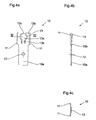
- the blocking element 10 illustrated in FIG. figure 4a has an essentially rectangular shape.
- the blocking element 10 comprises a first portion 10a shaped in size and shape at the first end 1a of the first profile 1 and the first end 6a of the core 6 and also intended to be inserted and retained in the handle of the chisel with wood.
- the second portion 10b of the blocking element 10 comprises lateral flanges 11 illustrated in FIGS. Figures 4b and 4c .
- the second portion 10b and the lateral flanges 11 are shaped so that the blocking element 10 can be inserted into the first section 1 and the core 6 is retained between said first section 1 and the blocking element 10 by the action combined with embedding the curved edges 2 of the first profile 1 and the lateral flanges 11.
- the blocking element 10 comprises on its first portion 10a a third hole 12 intended to cooperate with the second protrusion 8 of the core 6 to ensure the proper positioning of the blocking element 10 relative to the core 6 .
- the blocking element 10 further comprises a tongue 13 cut in its second portion 10b.
- Said tongue 13 is shaped so as to have a certain elasticity at a pressure along an axis perpendicular to the longitudinal axis of the blocking element 10.
- the tongue 13 has a substantially circular portion 13a providing an adequate support zone for the user and secured to the blocking element 10 by an arm 13b.
- the tongue 13 has at its free end a finger 13c whose function will be described below.
- the chisel according to the invention further comprises a sliding element 14 illustrated in FIGS. Figures 5a and 5b and having the shape of a substantially rectangular plate.
- the sliding element 14 comprises a first portion 14a preferably having two projections 15 intended to facilitate the handling of the sliding element 14 by the user.
- the end of this first portion 14a of the sliding element 14 has a cutout 17 intended to cooperate with the finger 13c of the tongue 13 of the blocking element 10.
- the second portion 14b of the sliding element 14 has lateral flanges 16 extending perpendicularly to the longitudinal axis of the sliding element on the side opposite to the projections 15. Again on the face opposite to that comprising the projections 15, the sliding element comprises a stop 18 intended to slide in the oblong opening 9 of the core 6.
- the lateral flanges 16 of the sliding element 14 are shaped in such a way that said sliding element 14 can move in the first section 1, said lateral flanges sliding between the curved edges 2 of the first profile 1 and the core 6.
- the core 6 is inserted into the first section 1, its positioning being guaranteed by the embedding of the first protuberance 7 of the core 6 in the first hole 3 of the first profile 1.
- the blocking element 10 is then inserted into the first section 1. Said blocking element is correctly positioned when the second protrusion 8 of the core 6 is correctly driven into the third hole 12 of the blocking element. Due to the shape of the first section 1, the core 6 and the blocking element 10, the latter can be extracted from the first section 1 only by moving it along the longitudinal axis of the first profile. In particular, said blocking element can not be extracted vertically from the first section 1. Thus, once in their operating position, the blocking element 10 is driven into the first section 1 and also blocks the core 6 in said first section 1.
- the size of the core 6 is such that, once the first profile 1, the core 6 and the blocking element 10 in their operating position, the positioning holes 5 are not covered by the core and are accessible to the user as shown on the figure 8 .
- the sliding element 14 is inserted into the first section 1 so that the lateral flanges 16 of said sliding element 14 encase the core 6. Due to the shape of the first profile 1 and the sliding element 14, the latter can not be extracted from the first profile vertically. As for the blocking element 10, the sliding element 14 can only be moved laterally along the longitudinal axis of the first section 1.
- the displacements of the sliding element 14 with respect to the first section 1 are limited by the stroke of the abutment 18 in the oblong opening 9 of the core 6.
- the finger 13c of the tongue 13 of the blocking element 10 cooperates with the cutout 17 of the sliding element 14 to block it and prevent it from sliding further in relation to the first section 1.
- This closed position is illustrated in FIG. figure 7 .
- the size of the sliding element 14 is such that, in this closed position, the sliding element covers the positioning holes 5 of the first profile 1, these being then inaccessible to the user.
- the user To move the sliding element 14 in its open position, the user must then press the tongue 13, via its circular portion 13a, so as to release the finger 13c of the cutout 17. While maintaining the pressure on the tongue 13, the user can then slide the sliding element 14 over the blocking element 10, thereby uncovering the positioning holes 5 of the first section 1.
- the travel of the sliding element 14 is limited by the stop 18 sliding in the oblong opening 9.
- the blocking element 10 and the sliding element 14 are shaped so that the latter can slide over the first. This open position is illustrated in the figure 8 .
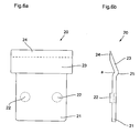
- the chisel according to the second embodiment of the invention further comprises a removable blade 20 illustrated in FIG. figure 6a .
- the removable blade 20 comprises a fixing plate 21 having retaining means having for example the shape of a first and second lugs 22 intended to cooperate with the positioning holes 5 of the first profile 1.
- the size and shape of the fixing plate are such that it can be inserted in the first profile 1 and between said profile 1 and the sliding element 14.
- the removable blade 20 further comprises a cutting plate 23 secured to the fixing plate 21.
- the free end of the cutting plate 23 has a cutting edge 24.
- the size of the cutting plate and the angle of the cutting edge may vary depending on the type of blade.
- the removable blade 20 When the sliding element 14 is in the open position, the removable blade 20 is placed in the first profile 1. The proper positioning of the blade 20 is guaranteed by the latching of the first and second lugs 22 in the positioning holes 5 of the first profile 1. To secure the removable blade With the wood chisel according to the invention, the user must now move the sliding element 14 in its closed position by sliding it relative to the first section 1. Once the sliding element in its closed position, the plate fixing 21 of the removable blade 20 is completely covered by the sliding member 14, it thus maintains the removable blade 20 secured to the chisel according to the invention.
- the tongue 13 could be replaced by any suitable elastic force.
- the various positioning means such as protuberances, recesses, abutments could be replaced by any other appropriate positioning means.
- the angle ⁇ between the cutting plate 23 and the fixing plate 21 of the removable blade may vary depending on the type of blade.
- the cutting deck 23 is adjusted relative to the fixing plate 21 so as to form a bulge 25 shaped so that any chips of material removed during the use of the wood chisel according to the invention can not come sliding between the sliding element 14 and the removable blade 20.
- This variant of the removable blade can also be applied to a removable blade for equipping a wood chisel according to the first embodiment.
- the souls 105, 6 described in the two embodiments above are in both cases optional.
Landscapes
- Engineering & Computer Science (AREA)
- Mechanical Engineering (AREA)
- Knives (AREA)
Claims (8)
- Werkzeug, insbesondere Stemmeisen, das ein erstes Profilteil (100; 1), ein zweites Profilteil (103; 10, 14) und eine herausnehmbare Klinge (106; 20) umfasst, dadurch gekennzeichnet, dass das zweite Profilteil (103; 10, 14) in das erste getrieben wird, so dass die herausnehmbare Klinge zwischen dem ersten und dem zweiten Profilteil (100; 1; 103; 10, 14) eingesetzt werden kann und dort durch Reibung gehalten wird.
- Werkzeug nach Anspruch 1, dadurch gekennzeichnet, dass es außerdem einen Kern (6) umfasst, der zwischen dem ersten und dem zweiten Profilteil (100; 1; 103; 10, 14) positioniert ist.
- Werkzeug nach einem der vorhergehenden Ansprüche, dadurch gekennzeichnet, dass das erste und das zweite Profilteil (100, 103) eine längliche Öffnung (110) umfassen, die mit einem Loch (111), das in der herausnehmbaren Klinge (106) hergestellt wurde, zusammenwirkt, um das Zurückziehen der herausnehmbaren Klinge (106) in das erste und das zweite Profilteil (100, 103) zu ermöglichen.
- Werkzeug nach einem der Ansprüche 1 oder 2, dadurch gekennzeichnet, dass das zweite Profilteil ein in Bezug auf das erste Profilteil verschiebbares Element (14) umfasst, das zwischen einer ersten geöffneten Position, in der die herausnehmbare Klinge (20) auf dem ersten Profilteil (1) angeordnet werden kann, und einer geschlossenen Position, in der die herausnehmbare Klinge (20) zwischen dem ersten Profilteil (1) und dem verschiebbaren Element (14) gehalten wird, bewegt werden kann.
- Werkzeug nach Anspruch 4, dadurch gekennzeichnet, dass das zweite Profilteil außerdem Arretierungsmittel (10) umfasst, die von einem Benutzer betätigt werden können, um das verschiebbare Element in seiner geschlossenen Position zu arretieren.
- Werkzeug nach einem der Ansprüche 4 und 5, dadurch gekennzeichnet, dass das erste Profilteil erste Rückhaltemittel (5) umfasst, die mit zweiten Rückhaltemitteln (22), die auf der herausnehmbaren Klinge (20) vorliegen, zusammenwirken, um die herausnehmbare Klinge (20) auf dem ersten Profilteil zu positionieren, wenn das verschiebbare Element (14) des zweiten Profilteils sich in seiner geöffneten Position befindet.
- Herausnehmbare Klinge (106; 20), die zum Ausstatten eines Werkzeugs, insbesondere eines Stemmeisens, nach einem der Ansprüche 1 bis 6 bestimmt ist.
- Herausnehmbare Klinge (106; 20) nach Anspruch 7, dadurch gekennzeichnet, dass sie eine Ausbauchung (25) umfasst, die dazu angepasst ist, jegliche Materialspäne daran zu hindern, zwischen die herausnehmbare Klinge (20) und das erste und/oder das zweite Profilteil einzudringen.
Priority Applications (4)
| Application Number | Priority Date | Filing Date | Title |
|---|---|---|---|
| EP10003752A EP2374579B1 (de) | 2010-04-08 | 2010-04-08 | Meissel für Holz und Klinge für Meissel |
| US13/071,805 US8869404B2 (en) | 2010-04-08 | 2011-03-25 | Wood chisel and blade for a wood chisel |
| JP2011085285A JP5815268B2 (ja) | 2010-04-08 | 2011-04-07 | 木材用のみ及び木材用のみのためのブレード |
| US14/510,468 US9095967B2 (en) | 2010-04-08 | 2014-10-09 | Wood chisel and blade for a wood chisel |
Applications Claiming Priority (1)
| Application Number | Priority Date | Filing Date | Title |
|---|---|---|---|
| EP10003752A EP2374579B1 (de) | 2010-04-08 | 2010-04-08 | Meissel für Holz und Klinge für Meissel |
Publications (2)
| Publication Number | Publication Date |
|---|---|
| EP2374579A1 EP2374579A1 (de) | 2011-10-12 |
| EP2374579B1 true EP2374579B1 (de) | 2012-08-22 |
Family
ID=42542812
Family Applications (1)
| Application Number | Title | Priority Date | Filing Date |
|---|---|---|---|
| EP10003752A Active EP2374579B1 (de) | 2010-04-08 | 2010-04-08 | Meissel für Holz und Klinge für Meissel |
Country Status (3)
| Country | Link |
|---|---|
| US (2) | US8869404B2 (de) |
| EP (1) | EP2374579B1 (de) |
| JP (1) | JP5815268B2 (de) |
Families Citing this family (7)
| Publication number | Priority date | Publication date | Assignee | Title |
|---|---|---|---|---|
| USD865308S1 (en) * | 2018-01-25 | 2019-10-29 | SEVENTY EIGHT Co., Ltd | Hand scraper |
| USD860565S1 (en) * | 2018-03-29 | 2019-09-17 | Hong Ann Tool Industries Co., Ltd. | Scraper |
| USD893273S1 (en) * | 2019-04-03 | 2020-08-18 | Slice, Inc. | Double-sided narrow chisel blade |
| USD902966S1 (en) | 2019-05-21 | 2020-11-24 | Christopher Lee Caliendo | Rhombus negative rake wood turning blade |
| USD902968S1 (en) | 2019-05-21 | 2020-11-24 | Christopher Lee Caliendo | Squared negative rake wood turning blade |
| USD902967S1 (en) | 2019-05-21 | 2020-11-24 | Christopher Lee Caliendo | Round negative rake wood turning blade |
| CN112895036B (zh) * | 2021-01-13 | 2024-01-05 | 祐樘(南京)软件科技有限公司 | 一种木工锁开槽器 |
Family Cites Families (53)
| Publication number | Priority date | Publication date | Assignee | Title |
|---|---|---|---|---|
| US404554A (en) * | 1889-06-04 | Carpenter s chisel | ||
| US447776A (en) * | 1891-03-10 | Clamp for holding chisels | ||
| US903093A (en) * | 1908-04-07 | 1908-11-03 | Burton W Howe | Chisel. |
| US940478A (en) * | 1908-12-09 | 1909-11-16 | Warren Rawalt | Farrier's implement. |
| US1082802A (en) * | 1913-04-02 | 1913-12-30 | Peter Full | Scraping-tool. |
| US1092447A (en) * | 1913-08-21 | 1914-04-07 | Charles S Leland | Glazier's tool. |
| US1334686A (en) * | 1919-07-23 | 1920-03-23 | Whyte William Sidney | Pneumatic chisel |
| US1442084A (en) * | 1920-08-06 | 1923-01-16 | Westinghouse Electric & Mfg Co | Tool handle and method of making the same |
| US1476120A (en) * | 1920-09-30 | 1923-12-04 | Thos H Dallett Co | Bush chisel |
| US1471461A (en) * | 1922-04-11 | 1923-10-23 | Richard J Harmon | Cold chisel |
| US1603771A (en) * | 1922-09-05 | 1926-10-19 | Marshall Wells Company | Tool handle |
| GB295832A (en) * | 1927-08-23 | 1928-08-23 | Gibson Stables | Improvements in or relating to chisels |
| US2053707A (en) * | 1934-08-22 | 1936-09-08 | Gordon C Farmer | Tool guard |
| US2291514A (en) * | 1939-05-05 | 1942-07-28 | Warner Mfg Co | Hand scraper |
| US2475041A (en) * | 1946-02-25 | 1949-07-05 | Joseph M Mattson | Percussive type wood chisel |
| US2565193A (en) * | 1948-06-07 | 1951-08-21 | Louis P Meconi | Bit clamp for carpenter's plane |
| US3906626A (en) * | 1974-04-19 | 1975-09-23 | Becton Dickinson Co | Disposable surgical scalpel |
| GB1586984A (en) * | 1978-04-05 | 1981-03-25 | Stanley Tools Ltd | Chisel |
| DE8406730U1 (de) * | 1984-03-05 | 1984-04-26 | Waldemar Link (Gmbh & Co), 2000 Hamburg | Chirurgischer Meißel |
| US4937939A (en) * | 1987-02-18 | 1990-07-03 | Fisher Francis J | Remotedly operated chimney chisel |
| US4805818A (en) * | 1987-06-19 | 1989-02-21 | Harrison Dan W | Knife sheath and tool device |
| GB8716418D0 (en) * | 1987-07-13 | 1987-08-19 | Lemaire D | Pocket knife |
| US4821419A (en) * | 1987-08-28 | 1989-04-18 | Lee Valley Tools Ltd. | Blind nailer |
| JPH021074A (ja) | 1988-06-03 | 1990-01-05 | Nippon Seimitsu Kogyo Kk | 画像読取装置 |
| JPH0527151Y2 (de) * | 1988-06-14 | 1993-07-09 | ||
| US4872231A (en) * | 1988-07-19 | 1989-10-10 | Willard Gustavsen | Impact blade tool |
| US4936014A (en) * | 1989-04-06 | 1990-06-26 | Johnson Level And Tool (Canada) Inc. | Utility knife |
| JPH0372868U (de) * | 1989-11-21 | 1991-07-23 | ||
| JPH0655Y2 (ja) * | 1990-01-17 | 1994-01-05 | 株式会社貝印刃物開発センター | ナイフにおける背金の構造 |
| US5312429A (en) * | 1992-07-27 | 1994-05-17 | Devon Industries, Inc. | Scalpel handle and blade release assembly |
| US5330492A (en) * | 1992-10-21 | 1994-07-19 | Dlh Concepts, Inc. | Safety scalpel |
| AU1229797A (en) * | 1996-11-08 | 1998-05-14 | First Australia Design Technology Pty Limited | Hand tools with replaceable tips |
| JP3802651B2 (ja) * | 1997-05-15 | 2006-07-26 | 株式会社ダスキン | パイプの接続構造 |
| US5927779A (en) * | 1997-10-31 | 1999-07-27 | Melnor Canada Ltd. | Tool, a kit and a method for assembling a tool, having an elongate shaft member and a blade member |
| JP3716399B2 (ja) * | 1998-03-20 | 2005-11-16 | 株式会社ケイディエス | カッターナイフ |
| AU712212B3 (en) * | 1999-07-15 | 1999-10-28 | Occupational & Medical Innovations Ltd | A surgical scalpel with retractable guard |
| US6510612B1 (en) * | 2001-07-11 | 2003-01-28 | Marian Cybulski | Knife |
| US6966113B2 (en) * | 2001-07-23 | 2005-11-22 | Repetto Llc | Utility knife |
| US6813833B2 (en) * | 2002-01-16 | 2004-11-09 | Nottingham-Spirk Design Associates, Inc. | Utility knife |
| US6769147B1 (en) * | 2002-07-03 | 2004-08-03 | Shawn Stubbs | Multi-use broad bladed knife |
| US6898855B2 (en) * | 2002-12-02 | 2005-05-31 | Gordon Sinclair Jones | Ergonomic Scraper |
| US7114824B2 (en) * | 2004-05-03 | 2006-10-03 | Picone Products, Inc. | Multi-functional tool with interchangeable adjustable wrench head unit |
| US7181848B1 (en) * | 2004-07-06 | 2007-02-27 | Tochtrop Jeffrey L | Multiple use rotary cutting device |
| USD534401S1 (en) * | 2004-09-08 | 2007-01-02 | Roger Duffin | Saw blade |
| US7257896B2 (en) * | 2005-03-11 | 2007-08-21 | Lisle Corporation | Tool for breaking spot welds |
| US20080189957A1 (en) * | 2007-02-12 | 2008-08-14 | The Stanley Works | Bi-metal chisel blade |
| US8020876B2 (en) * | 2007-04-04 | 2011-09-20 | Hung Wei Lin | Tool having clamping chuck |
| US8006389B2 (en) * | 2007-05-21 | 2011-08-30 | Pacific Handy Cutter, Inc. | Pocket safety cutter |
| CN101992462B (zh) * | 2009-08-14 | 2015-08-19 | 杭州巨星科技股份有限公司 | 工具手柄及其制造方法 |
| US20110041346A1 (en) * | 2009-08-24 | 2011-02-24 | Kun-Chen Chen | Chisel with interchangeable blade |
| US8141255B2 (en) * | 2009-08-29 | 2012-03-27 | Cheng-Wei Su | Multi-impact hand tool |
| US8402663B2 (en) * | 2010-08-11 | 2013-03-26 | William J. McHenry | Two-piece hand tool |
| US8650993B2 (en) * | 2012-04-09 | 2014-02-18 | Shou-Hung Chen | Fixing device for a tool member |
-
2010
- 2010-04-08 EP EP10003752A patent/EP2374579B1/de active Active
-
2011
- 2011-03-25 US US13/071,805 patent/US8869404B2/en active Active
- 2011-04-07 JP JP2011085285A patent/JP5815268B2/ja active Active
-
2014
- 2014-10-09 US US14/510,468 patent/US9095967B2/en active Active
Also Published As
| Publication number | Publication date |
|---|---|
| JP2011218809A (ja) | 2011-11-04 |
| JP5815268B2 (ja) | 2015-11-17 |
| EP2374579A1 (de) | 2011-10-12 |
| US9095967B2 (en) | 2015-08-04 |
| US20110247218A1 (en) | 2011-10-13 |
| US20150020390A1 (en) | 2015-01-22 |
| US8869404B2 (en) | 2014-10-28 |
Similar Documents
| Publication | Publication Date | Title |
|---|---|---|
| EP2374579B1 (de) | Meissel für Holz und Klinge für Meissel | |
| EP2782469B1 (de) | Abnehmbare verbindungsvorrichtung eines armbandes | |
| EP1237453B1 (de) | Griffelement für kochgeschirr | |
| EP2319349B1 (de) | Vorrichtung zum Befestigen eines Armbands auf einem Uhrengehäuse | |
| EP2135129A1 (de) | Mittel zur schnellen fixierung für brillen-seitenstücke | |
| EP2631044A1 (de) | Schneidenverriegelungsvorrichtung für den ausgeklappten Zustand für Messer mit einklappbarer Schneide | |
| FR2899725A1 (fr) | Bloc accumulateur pour l'alimentation d'appareils electriques | |
| EP2258955B1 (de) | Mutternklemmvorrichtung, geeignet zur Positionierung am Rand einer Unterlage wie etwa einer Platte | |
| FR3016544A1 (fr) | Outil monte sur soie a manche interchangeable | |
| EP3529867B1 (de) | Elektrisches gerät mit einer verriegelungsvorrichtung für eine montageschiene | |
| EP1635232B1 (de) | Armbanduhrgehäuse | |
| FR2747955A1 (fr) | Dispositif coupe-carreau du type a decoupe ronde | |
| FR2705606A1 (fr) | Dispositif de liaison articulée entre un manche et une lame notamment. | |
| FR2965456A1 (fr) | Chaussure a semelle et tige interchangeables l'une par rapport a l'autre. | |
| EP1241764B1 (de) | Sockel- und Mechanismusanordnung für ein elektrisches Gerät mit verbesserten Schnappbefestigungsmitteln zwischen Sockel und Mechanismus | |
| FR2552007A1 (fr) | Perfectionnements au dispositif de crantage des couteaux a lame retractable | |
| WO2018050819A1 (fr) | Terminal de paiement électronique avec élément monobloc de lecture de carte magnétique comprenant une lame métallique de glissement, procédé de montage correspondant | |
| FR2821580A1 (fr) | Outil de coupe perfectionne | |
| FR2908343A1 (fr) | Couteau a lame amovible a manche a deux parties separables | |
| EP2539722B1 (de) | Gehäuse mit mitteln zum befestigen auf einer trägerplatte | |
| EP1241763B1 (de) | Sockel- und Mechanismusanordnung für ein elektrisches Gerät mit verbesserten Schnappbefestigungsmitteln zwischen Sockel und Mechanismus | |
| FR2936542A1 (fr) | Gache reglable de serrure | |
| FR2891297A1 (fr) | Dispositif de liaison de tetiere | |
| FR2928575A1 (fr) | Couteau a lame retractable | |
| FR2858119A1 (fr) | Dispositif de raccordement electrique a contact protege |
Legal Events
| Date | Code | Title | Description |
|---|---|---|---|
| PUAI | Public reference made under article 153(3) epc to a published international application that has entered the european phase |
Free format text: ORIGINAL CODE: 0009012 |
|
| AK | Designated contracting states |
Kind code of ref document: A1 Designated state(s): AT BE BG CH CY CZ DE DK EE ES FI FR GB GR HR HU IE IS IT LI LT LU LV MC MK MT NL NO PL PT RO SE SI SK SM TR |
|
| AX | Request for extension of the european patent |
Extension state: AL BA ME RS |
|
| 17P | Request for examination filed |
Effective date: 20111027 |
|
| GRAP | Despatch of communication of intention to grant a patent |
Free format text: ORIGINAL CODE: EPIDOSNIGR1 |
|
| GRAS | Grant fee paid |
Free format text: ORIGINAL CODE: EPIDOSNIGR3 |
|
| GRAA | (expected) grant |
Free format text: ORIGINAL CODE: 0009210 |
|
| AK | Designated contracting states |
Kind code of ref document: B1 Designated state(s): AT BE BG CH CY CZ DE DK EE ES FI FR GB GR HR HU IE IS IT LI LT LU LV MC MK MT NL NO PL PT RO SE SI SK SM TR |
|
| REG | Reference to a national code |
Ref country code: GB Ref legal event code: FG4D Free format text: NOT ENGLISH |
|
| REG | Reference to a national code |
Ref country code: CH Ref legal event code: EP |
|
| REG | Reference to a national code |
Ref country code: IE Ref legal event code: FG4D Free format text: LANGUAGE OF EP DOCUMENT: FRENCH |
|
| REG | Reference to a national code |
Ref country code: AT Ref legal event code: REF Ref document number: 571704 Country of ref document: AT Kind code of ref document: T Effective date: 20120915 |
|
| REG | Reference to a national code |
Ref country code: CH Ref legal event code: NV Representative=s name: MICHELI & CIE SA |
|
| REG | Reference to a national code |
Ref country code: DE Ref legal event code: R096 Ref document number: 602010002324 Country of ref document: DE Effective date: 20121018 |
|
| REG | Reference to a national code |
Ref country code: SE Ref legal event code: TRGR |
|
| REG | Reference to a national code |
Ref country code: NL Ref legal event code: VDEP Effective date: 20120822 |
|
| REG | Reference to a national code |
Ref country code: LT Ref legal event code: MG4D Effective date: 20120822 |
|
| PG25 | Lapsed in a contracting state [announced via postgrant information from national office to epo] |
Ref country code: LT Free format text: LAPSE BECAUSE OF FAILURE TO SUBMIT A TRANSLATION OF THE DESCRIPTION OR TO PAY THE FEE WITHIN THE PRESCRIBED TIME-LIMIT Effective date: 20120822 Ref country code: NO Free format text: LAPSE BECAUSE OF FAILURE TO SUBMIT A TRANSLATION OF THE DESCRIPTION OR TO PAY THE FEE WITHIN THE PRESCRIBED TIME-LIMIT Effective date: 20121122 Ref country code: HR Free format text: LAPSE BECAUSE OF FAILURE TO SUBMIT A TRANSLATION OF THE DESCRIPTION OR TO PAY THE FEE WITHIN THE PRESCRIBED TIME-LIMIT Effective date: 20120822 Ref country code: IS Free format text: LAPSE BECAUSE OF FAILURE TO SUBMIT A TRANSLATION OF THE DESCRIPTION OR TO PAY THE FEE WITHIN THE PRESCRIBED TIME-LIMIT Effective date: 20121222 Ref country code: FI Free format text: LAPSE BECAUSE OF FAILURE TO SUBMIT A TRANSLATION OF THE DESCRIPTION OR TO PAY THE FEE WITHIN THE PRESCRIBED TIME-LIMIT Effective date: 20120822 |
|
| PG25 | Lapsed in a contracting state [announced via postgrant information from national office to epo] |
Ref country code: LV Free format text: LAPSE BECAUSE OF FAILURE TO SUBMIT A TRANSLATION OF THE DESCRIPTION OR TO PAY THE FEE WITHIN THE PRESCRIBED TIME-LIMIT Effective date: 20120822 Ref country code: SI Free format text: LAPSE BECAUSE OF FAILURE TO SUBMIT A TRANSLATION OF THE DESCRIPTION OR TO PAY THE FEE WITHIN THE PRESCRIBED TIME-LIMIT Effective date: 20120822 Ref country code: PT Free format text: LAPSE BECAUSE OF FAILURE TO SUBMIT A TRANSLATION OF THE DESCRIPTION OR TO PAY THE FEE WITHIN THE PRESCRIBED TIME-LIMIT Effective date: 20121224 Ref country code: GR Free format text: LAPSE BECAUSE OF FAILURE TO SUBMIT A TRANSLATION OF THE DESCRIPTION OR TO PAY THE FEE WITHIN THE PRESCRIBED TIME-LIMIT Effective date: 20121123 |
|
| PG25 | Lapsed in a contracting state [announced via postgrant information from national office to epo] |
Ref country code: NL Free format text: LAPSE BECAUSE OF FAILURE TO SUBMIT A TRANSLATION OF THE DESCRIPTION OR TO PAY THE FEE WITHIN THE PRESCRIBED TIME-LIMIT Effective date: 20120822 |
|
| PG25 | Lapsed in a contracting state [announced via postgrant information from national office to epo] |
Ref country code: DK Free format text: LAPSE BECAUSE OF FAILURE TO SUBMIT A TRANSLATION OF THE DESCRIPTION OR TO PAY THE FEE WITHIN THE PRESCRIBED TIME-LIMIT Effective date: 20120822 Ref country code: RO Free format text: LAPSE BECAUSE OF FAILURE TO SUBMIT A TRANSLATION OF THE DESCRIPTION OR TO PAY THE FEE WITHIN THE PRESCRIBED TIME-LIMIT Effective date: 20120822 Ref country code: CZ Free format text: LAPSE BECAUSE OF FAILURE TO SUBMIT A TRANSLATION OF THE DESCRIPTION OR TO PAY THE FEE WITHIN THE PRESCRIBED TIME-LIMIT Effective date: 20120822 Ref country code: EE Free format text: LAPSE BECAUSE OF FAILURE TO SUBMIT A TRANSLATION OF THE DESCRIPTION OR TO PAY THE FEE WITHIN THE PRESCRIBED TIME-LIMIT Effective date: 20120822 |
|
| PG25 | Lapsed in a contracting state [announced via postgrant information from national office to epo] |
Ref country code: SK Free format text: LAPSE BECAUSE OF FAILURE TO SUBMIT A TRANSLATION OF THE DESCRIPTION OR TO PAY THE FEE WITHIN THE PRESCRIBED TIME-LIMIT Effective date: 20120822 Ref country code: PL Free format text: LAPSE BECAUSE OF FAILURE TO SUBMIT A TRANSLATION OF THE DESCRIPTION OR TO PAY THE FEE WITHIN THE PRESCRIBED TIME-LIMIT Effective date: 20120822 |
|
| PLBE | No opposition filed within time limit |
Free format text: ORIGINAL CODE: 0009261 |
|
| STAA | Information on the status of an ep patent application or granted ep patent |
Free format text: STATUS: NO OPPOSITION FILED WITHIN TIME LIMIT |
|
| 26N | No opposition filed |
Effective date: 20130523 |
|
| PG25 | Lapsed in a contracting state [announced via postgrant information from national office to epo] |
Ref country code: BG Free format text: LAPSE BECAUSE OF FAILURE TO SUBMIT A TRANSLATION OF THE DESCRIPTION OR TO PAY THE FEE WITHIN THE PRESCRIBED TIME-LIMIT Effective date: 20121122 |
|
| REG | Reference to a national code |
Ref country code: DE Ref legal event code: R097 Ref document number: 602010002324 Country of ref document: DE Effective date: 20130523 |
|
| PG25 | Lapsed in a contracting state [announced via postgrant information from national office to epo] |
Ref country code: ES Free format text: LAPSE BECAUSE OF FAILURE TO SUBMIT A TRANSLATION OF THE DESCRIPTION OR TO PAY THE FEE WITHIN THE PRESCRIBED TIME-LIMIT Effective date: 20121203 |
|
| PG25 | Lapsed in a contracting state [announced via postgrant information from national office to epo] |
Ref country code: MC Free format text: LAPSE BECAUSE OF FAILURE TO SUBMIT A TRANSLATION OF THE DESCRIPTION OR TO PAY THE FEE WITHIN THE PRESCRIBED TIME-LIMIT Effective date: 20120822 Ref country code: CY Free format text: LAPSE BECAUSE OF FAILURE TO SUBMIT A TRANSLATION OF THE DESCRIPTION OR TO PAY THE FEE WITHIN THE PRESCRIBED TIME-LIMIT Effective date: 20120822 |
|
| REG | Reference to a national code |
Ref country code: IE Ref legal event code: MM4A |
|
| PG25 | Lapsed in a contracting state [announced via postgrant information from national office to epo] |
Ref country code: IE Free format text: LAPSE BECAUSE OF NON-PAYMENT OF DUE FEES Effective date: 20130408 |
|
| PG25 | Lapsed in a contracting state [announced via postgrant information from national office to epo] |
Ref country code: MT Free format text: LAPSE BECAUSE OF FAILURE TO SUBMIT A TRANSLATION OF THE DESCRIPTION OR TO PAY THE FEE WITHIN THE PRESCRIBED TIME-LIMIT Effective date: 20120822 |
|
| PG25 | Lapsed in a contracting state [announced via postgrant information from national office to epo] |
Ref country code: SM Free format text: LAPSE BECAUSE OF FAILURE TO SUBMIT A TRANSLATION OF THE DESCRIPTION OR TO PAY THE FEE WITHIN THE PRESCRIBED TIME-LIMIT Effective date: 20120822 |
|
| PG25 | Lapsed in a contracting state [announced via postgrant information from national office to epo] |
Ref country code: TR Free format text: LAPSE BECAUSE OF FAILURE TO SUBMIT A TRANSLATION OF THE DESCRIPTION OR TO PAY THE FEE WITHIN THE PRESCRIBED TIME-LIMIT Effective date: 20120822 |
|
| PG25 | Lapsed in a contracting state [announced via postgrant information from national office to epo] |
Ref country code: LU Free format text: LAPSE BECAUSE OF NON-PAYMENT OF DUE FEES Effective date: 20130408 Ref country code: MK Free format text: LAPSE BECAUSE OF FAILURE TO SUBMIT A TRANSLATION OF THE DESCRIPTION OR TO PAY THE FEE WITHIN THE PRESCRIBED TIME-LIMIT Effective date: 20120822 Ref country code: HU Free format text: LAPSE BECAUSE OF FAILURE TO SUBMIT A TRANSLATION OF THE DESCRIPTION OR TO PAY THE FEE WITHIN THE PRESCRIBED TIME-LIMIT; INVALID AB INITIO Effective date: 20100408 |
|
| REG | Reference to a national code |
Ref country code: FR Ref legal event code: PLFP Year of fee payment: 7 |
|
| REG | Reference to a national code |
Ref country code: FR Ref legal event code: PLFP Year of fee payment: 8 |
|
| REG | Reference to a national code |
Ref country code: FR Ref legal event code: PLFP Year of fee payment: 9 |
|
| PGFP | Annual fee paid to national office [announced via postgrant information from national office to epo] |
Ref country code: GB Payment date: 20240419 Year of fee payment: 15 |
|
| PGFP | Annual fee paid to national office [announced via postgrant information from national office to epo] |
Ref country code: DE Payment date: 20240418 Year of fee payment: 15 |
|
| PGFP | Annual fee paid to national office [announced via postgrant information from national office to epo] |
Ref country code: CH Payment date: 20240501 Year of fee payment: 15 |
|
| PGFP | Annual fee paid to national office [announced via postgrant information from national office to epo] |
Ref country code: AT Payment date: 20240419 Year of fee payment: 15 |
|
| PGFP | Annual fee paid to national office [announced via postgrant information from national office to epo] |
Ref country code: IT Payment date: 20240424 Year of fee payment: 15 Ref country code: FR Payment date: 20240426 Year of fee payment: 15 |
|
| PGFP | Annual fee paid to national office [announced via postgrant information from national office to epo] |
Ref country code: SE Payment date: 20240418 Year of fee payment: 15 Ref country code: BE Payment date: 20240418 Year of fee payment: 15 |