EP2374010B1 - Turbulenzsensor und schaufelzustandssensorsystem - Google Patents
Turbulenzsensor und schaufelzustandssensorsystem Download PDFInfo
- Publication number
- EP2374010B1 EP2374010B1 EP09801662.9A EP09801662A EP2374010B1 EP 2374010 B1 EP2374010 B1 EP 2374010B1 EP 09801662 A EP09801662 A EP 09801662A EP 2374010 B1 EP2374010 B1 EP 2374010B1
- Authority
- EP
- European Patent Office
- Prior art keywords
- sensor
- membrane
- turbulence
- cavity
- sensor system
- Prior art date
- Legal status (The legal status is an assumption and is not a legal conclusion. Google has not performed a legal analysis and makes no representation as to the accuracy of the status listed.)
- Not-in-force
Links
- 239000012528 membrane Substances 0.000 claims description 80
- 230000003287 optical effect Effects 0.000 claims description 21
- 238000009825 accumulation Methods 0.000 claims description 14
- 238000006073 displacement reaction Methods 0.000 claims description 10
- 239000000463 material Substances 0.000 claims description 6
- 239000013307 optical fiber Substances 0.000 description 13
- 239000000835 fiber Substances 0.000 description 11
- 238000005259 measurement Methods 0.000 description 7
- 238000000034 method Methods 0.000 description 6
- 238000004458 analytical method Methods 0.000 description 4
- 238000009434 installation Methods 0.000 description 4
- 238000012423 maintenance Methods 0.000 description 4
- 238000001514 detection method Methods 0.000 description 3
- 230000006870 function Effects 0.000 description 3
- 230000001965 increasing effect Effects 0.000 description 3
- 238000012360 testing method Methods 0.000 description 3
- 238000010586 diagram Methods 0.000 description 2
- 239000007789 gas Substances 0.000 description 2
- 239000011261 inert gas Substances 0.000 description 2
- 230000005693 optoelectronics Effects 0.000 description 2
- 230000010355 oscillation Effects 0.000 description 2
- 230000000737 periodic effect Effects 0.000 description 2
- 230000002085 persistent effect Effects 0.000 description 2
- 238000012545 processing Methods 0.000 description 2
- 230000000007 visual effect Effects 0.000 description 2
- 238000013528 artificial neural network Methods 0.000 description 1
- 238000007664 blowing Methods 0.000 description 1
- 230000000739 chaotic effect Effects 0.000 description 1
- 239000004020 conductor Substances 0.000 description 1
- 238000010276 construction Methods 0.000 description 1
- 230000001276 controlling effect Effects 0.000 description 1
- 230000007797 corrosion Effects 0.000 description 1
- 238000005260 corrosion Methods 0.000 description 1
- 230000006866 deterioration Effects 0.000 description 1
- 230000000694 effects Effects 0.000 description 1
- 230000005611 electricity Effects 0.000 description 1
- 238000005206 flow analysis Methods 0.000 description 1
- 230000001771 impaired effect Effects 0.000 description 1
- 238000011065 in-situ storage Methods 0.000 description 1
- 230000001939 inductive effect Effects 0.000 description 1
- 238000010422 painting Methods 0.000 description 1
- 238000003909 pattern recognition Methods 0.000 description 1
- 230000002028 premature Effects 0.000 description 1
- 230000001105 regulatory effect Effects 0.000 description 1
- 230000004043 responsiveness Effects 0.000 description 1
- 230000002441 reversible effect Effects 0.000 description 1
- 238000007789 sealing Methods 0.000 description 1
- 230000035945 sensitivity Effects 0.000 description 1
- 230000011664 signaling Effects 0.000 description 1
Images


Classifications
-
- G—PHYSICS
- G01—MEASURING; TESTING
- G01P—MEASURING LINEAR OR ANGULAR SPEED, ACCELERATION, DECELERATION, OR SHOCK; INDICATING PRESENCE, ABSENCE, OR DIRECTION, OF MOVEMENT
- G01P13/00—Indicating or recording presence, absence, or direction, of movement
- G01P13/0006—Indicating or recording presence, absence, or direction, of movement of fluids or of granulous or powder-like substances
- G01P13/0066—Indicating or recording presence, absence, or direction, of movement of fluids or of granulous or powder-like substances by using differences of pressure in the fluid
-
- F—MECHANICAL ENGINEERING; LIGHTING; HEATING; WEAPONS; BLASTING
- F03—MACHINES OR ENGINES FOR LIQUIDS; WIND, SPRING, OR WEIGHT MOTORS; PRODUCING MECHANICAL POWER OR A REACTIVE PROPULSIVE THRUST, NOT OTHERWISE PROVIDED FOR
- F03D—WIND MOTORS
- F03D80/00—Details, components or accessories not provided for in groups F03D1/00 - F03D17/00
-
- F—MECHANICAL ENGINEERING; LIGHTING; HEATING; WEAPONS; BLASTING
- F03—MACHINES OR ENGINES FOR LIQUIDS; WIND, SPRING, OR WEIGHT MOTORS; PRODUCING MECHANICAL POWER OR A REACTIVE PROPULSIVE THRUST, NOT OTHERWISE PROVIDED FOR
- F03D—WIND MOTORS
- F03D17/00—Monitoring or testing of wind motors, e.g. diagnostics
-
- F—MECHANICAL ENGINEERING; LIGHTING; HEATING; WEAPONS; BLASTING
- F03—MACHINES OR ENGINES FOR LIQUIDS; WIND, SPRING, OR WEIGHT MOTORS; PRODUCING MECHANICAL POWER OR A REACTIVE PROPULSIVE THRUST, NOT OTHERWISE PROVIDED FOR
- F03D—WIND MOTORS
- F03D80/00—Details, components or accessories not provided for in groups F03D1/00 - F03D17/00
- F03D80/40—Ice detection; De-icing means
-
- G—PHYSICS
- G01—MEASURING; TESTING
- G01B—MEASURING LENGTH, THICKNESS OR SIMILAR LINEAR DIMENSIONS; MEASURING ANGLES; MEASURING AREAS; MEASURING IRREGULARITIES OF SURFACES OR CONTOURS
- G01B11/00—Measuring arrangements characterised by the use of optical techniques
- G01B11/16—Measuring arrangements characterised by the use of optical techniques for measuring the deformation in a solid, e.g. optical strain gauge
- G01B11/161—Measuring arrangements characterised by the use of optical techniques for measuring the deformation in a solid, e.g. optical strain gauge by interferometric means
-
- G—PHYSICS
- G01—MEASURING; TESTING
- G01H—MEASUREMENT OF MECHANICAL VIBRATIONS OR ULTRASONIC, SONIC OR INFRASONIC WAVES
- G01H9/00—Measuring mechanical vibrations or ultrasonic, sonic or infrasonic waves by using radiation-sensitive means, e.g. optical means
- G01H9/004—Measuring mechanical vibrations or ultrasonic, sonic or infrasonic waves by using radiation-sensitive means, e.g. optical means using fibre optic sensors
- G01H9/006—Measuring mechanical vibrations or ultrasonic, sonic or infrasonic waves by using radiation-sensitive means, e.g. optical means using fibre optic sensors the vibrations causing a variation in the relative position of the end of a fibre and another element
-
- G—PHYSICS
- G01—MEASURING; TESTING
- G01M—TESTING STATIC OR DYNAMIC BALANCE OF MACHINES OR STRUCTURES; TESTING OF STRUCTURES OR APPARATUS, NOT OTHERWISE PROVIDED FOR
- G01M9/00—Aerodynamic testing; Arrangements in or on wind tunnels
- G01M9/06—Measuring arrangements specially adapted for aerodynamic testing
- G01M9/065—Measuring arrangements specially adapted for aerodynamic testing dealing with flow
-
- G—PHYSICS
- G01—MEASURING; TESTING
- G01P—MEASURING LINEAR OR ANGULAR SPEED, ACCELERATION, DECELERATION, OR SHOCK; INDICATING PRESENCE, ABSENCE, OR DIRECTION, OF MOVEMENT
- G01P13/00—Indicating or recording presence, absence, or direction, of movement
- G01P13/0006—Indicating or recording presence, absence, or direction, of movement of fluids or of granulous or powder-like substances
- G01P13/0073—Indicating or recording presence, absence, or direction, of movement of fluids or of granulous or powder-like substances by using vibrations generated by the fluid
-
- F—MECHANICAL ENGINEERING; LIGHTING; HEATING; WEAPONS; BLASTING
- F05—INDEXING SCHEMES RELATING TO ENGINES OR PUMPS IN VARIOUS SUBCLASSES OF CLASSES F01-F04
- F05B—INDEXING SCHEME RELATING TO WIND, SPRING, WEIGHT, INERTIA OR LIKE MOTORS, TO MACHINES OR ENGINES FOR LIQUIDS COVERED BY SUBCLASSES F03B, F03D AND F03G
- F05B2270/00—Control
- F05B2270/30—Control parameters, e.g. input parameters
- F05B2270/322—Control parameters, e.g. input parameters the detection or prediction of a wind gust
-
- F—MECHANICAL ENGINEERING; LIGHTING; HEATING; WEAPONS; BLASTING
- F05—INDEXING SCHEMES RELATING TO ENGINES OR PUMPS IN VARIOUS SUBCLASSES OF CLASSES F01-F04
- F05B—INDEXING SCHEME RELATING TO WIND, SPRING, WEIGHT, INERTIA OR LIKE MOTORS, TO MACHINES OR ENGINES FOR LIQUIDS COVERED BY SUBCLASSES F03B, F03D AND F03G
- F05B2270/00—Control
- F05B2270/80—Devices generating input signals, e.g. transducers, sensors, cameras or strain gauges
- F05B2270/804—Optical devices
-
- Y—GENERAL TAGGING OF NEW TECHNOLOGICAL DEVELOPMENTS; GENERAL TAGGING OF CROSS-SECTIONAL TECHNOLOGIES SPANNING OVER SEVERAL SECTIONS OF THE IPC; TECHNICAL SUBJECTS COVERED BY FORMER USPC CROSS-REFERENCE ART COLLECTIONS [XRACs] AND DIGESTS
- Y02—TECHNOLOGIES OR APPLICATIONS FOR MITIGATION OR ADAPTATION AGAINST CLIMATE CHANGE
- Y02E—REDUCTION OF GREENHOUSE GAS [GHG] EMISSIONS, RELATED TO ENERGY GENERATION, TRANSMISSION OR DISTRIBUTION
- Y02E10/00—Energy generation through renewable energy sources
- Y02E10/70—Wind energy
- Y02E10/72—Wind turbines with rotation axis in wind direction
Definitions
- the present invention relates to a turbulence sensor as part of a blade condition sensor system, and in particular to a sensor system for installation in a wind turbine to detect accumulated matter such as dirt and ice on wind turbine components.
- Figure 1 illustrates a wind turbine 1, comprising a wind turbine tower 2 on which a wind turbine nacelle 3 is mounted.
- a wind turbine rotor 4 comprising at least one wind turbine blade 5 is mounted on a hub 6.
- the hub 6 is connected to the nacelle 3 through a low speed shaft (not shown) extending from the nacelle front.
- the wind turbine illustrated in Figure 1 may be a small model intended for domestic or light utility usage, or may be a large model used, such as those that are suitable for use in large scale electricity generation on a wind farm for example. In the latter case, the diameter of the rotor could be as large as 100 metres or more.
- Wind turbines are often located in areas where conditions are harsh, such as offshore, coastal, or elevated areas, and during operation unwanted matter, such as ice and dirt, can often accumulate on the surface of the wind turbine components. Ice in particular can accumulate very rapidly as a result of sudden changes in climate conditions.
- DE 31 06 624 discloses a method of controlling the gearbox of a wind turbine.
- US 2004/252290 discloses methods of using an optical strain gauge, including a wind measurement device.
- DE 199 23 087 discloses a device for measuring pressure, sounds, and/or vibration, particularly for flow analysis on missiles.
- GB 2105846 discloses a vortex flowmeter.
- GB 2335108 discloses an optical microphone comprising a light source, a photodetector and a sound-sensitive membrane with a reflective surface.
- US 7355720 discloses an optical displacement sensor using a vertical-cavity surface-emitting laser coupled to an optical cavity formed by a movable membrane.
- a plurality of turbulence sensors for a wind turbine component having a cavity are provided in a sensor system for detecting the surface condition of the wind turbine component.
- the sensor system also comprises a memory and a processor.
- Each turbulence sensor comprises: a sensor membrane, for detecting the turbulence of air flow past a surface of the wind turbine component, wherein the sensor membrane is integral to the surface, and covers at least part of the cavity; a light source located in the sensor cavity for illuminating the surface of the sensor membrane inside the cavity; a light detector located in the cavity for detecting light reflected from the surface of the membrane, and for providing an output to a processor, the processor determining from the output a turbulence value for the air flow across the sensor membrane.
- the processor determines a condition of the component surface from the output received from the turbulence sensors, the memory records the outputs received from the turbulence sensors over a period of time, and the processor determines a condition of the component surface based on a change in the outputs compared with past outputs.
- the condition detected is the accumulation of matter on the component surface.
- the invention provides a sensitive sensor system due to the fact that small displacements of the sensor membrane can be detected using the light source and detector. Further, the sensor is relatively easy to install and can be situated in the wind turbine blade for protection, and to ensure that the presence of the sensor does not interfere with the measurement. As there are few moving parts, the sensor is resistant to extreme changes of temperature.
- the memory records the outputs received from the turbulence sensors over a period of time, and the processor determines a condition of the blade surface based on a change in the outputs compared with past outputs.
- This allows the past outputs of the turbulence sensor to act as a reference for comparison with the instantaneous or current readings being taken. Accumulation of dirt for example, may manifest itself as a gradual increase in the turbulence detected. Ice accumulation on the other hand may occur quickly over a number of hours.
- the sensor system comprises a plurality of sensors on the windward and leeward sides of the blade, so that a complete sensor view is obtained.
- the light source and light detector in the cavity are optical fibres connected to an opto-electrical light source. This allows the use of electrical components in the sensor to be avoided, and means that the sensor will be resistant to lighting strikes. These are especially common for wind turbine blades. Any electrical components for the sensor can be housed in part of the wind turbine that is electrically shielded.
- the senor comprises an adder for adding light reflected from the surface of the membrane to a reference light signal to give an interference pattern that indicates displacement of the membrane.
- an interference pattern provides the most accurate way of interpreting the displacement of the membrane, as small displacements of the membrane can be used to give large variations in intensity.
- a sinusoidal intensity pattern is produced, meaning that information about the speed at which the displacement is occurring as well as the direction of displacement can be obtained from analysis of the sinusoidal frequency and rate of occurrence.
- the adder comprises a partial mirror located in the sensor cavity to reflect a portion of the light from the light source to the light detector and provide the reference light signal.
- a partial mirror located in the sensor cavity to reflect a portion of the light from the light source to the light detector and provide the reference light signal.
- the sensor cavity is sealed. This allows the cavity environment to be maintained at levels of humidity and temperature that ensure good operation of the sensor membrane.
- the cavity may be filled with a gas other than air, such as an inert gas.
- the sensor membrane may be formed of a different material to that from which the surface of the wind turbine component is formed. This allows it to be tailored more precisely to its function as a sensor, in terms of tension and responsiveness. Depending on installation, the sensor membrane may alternatively be formed by the blade surface itself.
- the turbulence sensor comprises a processor for analysing the sinusoidal variations in the interference pattern over a predetermined period of time to determine whether the air flow is turbulent.
- the processor may analyse the pattern using pattern recognition or statistical techniques and give a determination with an associated level of confidence. Analysis for a longer period of time may give a higher degree of confidence in the sensor outcome.
- the processor compares the outputs from the turbulence sensors of one wind turbine blade with those of another. This allows the processor to give an indication of whether the blades are mounted and operating correctly, and provides additional data for comparison of blade condition.
- the sensor system detects the accumulation of matter on the blade surface.
- the processor determines a condition of the blade surface, in which matter is taken to have accumulated on the blade surface, when a predetermined number of the turbulence sensors persistently indicate turbulence.
- the invention also provides a wind turbine comprising a turbulence sensor or a blade condition sensor system as described above.
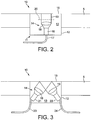
- Figure 2 illustrates a first example of a turbulence sensor according to a preferred embodiment of the invention.
- the turbulence sensor is shown in situ integrated into the blade of a wind turbine rotor, or other component.
- the sensor 10 comprises a sensor housing 11, having side walls 12 that define a cavity 13.
- sensor apparatus denoted generally by reference number 14, is situated.
- One surface of the sensor housing 11 is provided with a sensor membrane 15.
- the sensor 10 is mounted in the blade 5 such that the sensor membrane 15 separates the cavity 13 from the outside air, and such that the membrane 15 is in contact with the airflow across the surface of the blade.
- the cavity is entirely sealed off from the external environment by the side walls 12 and the membrane 15, so that movement of the membrane surface can be considered wholly attributable to variations in the air flow across the blade surface 5. Sealing the cavity also acts to keep the internal surface of the membrane clean, and allows the internal environment of the cavity to be regulated to avoid build up of moisture that could affect the sensor membrane 15 and apparatus 14.
- the cavity 13 may for example be filled with a gas other than air, such as an inert gas, that gives a better operating environment for the membrane.
- the blade surface 5 and the membrane 15 are arranged so that they form a smoothly continuous blade surface. It is undesirable both for the aerodynamic properties of the blade and for the sensitivity of the sensor if the connection between the membrane 15 and the blade surface is not continuous as this may introduce obstructions or impediments into the air flow.
- the membrane 15 is arranged such that it is susceptible to changes in air flow at the surface of the wind turbine component. It is therefore relatively thin, in some embodiments between 0.5 and 2mm, and is tensioned so that turbulent airflow will result in only a small movement of the membrane surface.
- An interference pattern is produced by shining light on to the membrane in order to measure the displacement of the membrane. In practice, therefore, a range of movement of the membrane of the order of several ⁇ m has been found advantageous, owing to the wavelength of the light used.
- the choice of the membrane material is critical to ensure it is suitable for measurement. A material that is too light and flexible will be too sensitive to changes in air flow even in laminar conditions will not be suitable for distinguishing turbulent and laminar flow.
- the material is therefore strong and stiff enough to ensure that only strong vibrations (in the range of 10 to 100Hz, say) from turbulent air flow give a sufficient interference signal.
- the sensor apparatus 14 can be installed in the rotor blade 5 under the outer surface, with or without the sensor housing 11 creating a sealed cavity for the apparatus. If the sensor 10 is installed into the rotor blade 5 or other wind turbine component, as a separate unit, then a hole of diameter 30 to 100mm has been found adequate to accommodate the sensor housing 11 and apparatus 14.
- Sensor apparatus 14 comprises a light source 16 aimed at the membrane 15. Where possible, it is advantageous to avoid the use of electrical components in rotor blades as they are more susceptible to damage from lighting strikes.
- the light source 16 preferably comprises an optical fibre 17 connected to an opto-electronic light source, such as a photo-diode or laser, located remotely in the rotor blade hub.
- the light source 16 constitutes the exposed end of the optical fibre 17 and a suitable mount to support the fibre in the sensor cavity and ensure that it is securely aimed at the membrane 15.
- the light source 16 comprising the optical fibre 17 also acts as a receiver for light that is reflected back from the membrane 15.
- the light source 16 is therefore arranged perpendicularly to the membrane 15 so that at least some of the reflected light from the membrane will be incident on the open end of the optical fibre.
- the apparatus 14 optionally comprises one or more lenses 18 provided between the optical fibre 17 and the membrane 15. In this way, a beam of light 19 emitted from the fibre 17 may be focussed into a tighter beam incident on the membrane and the beam reflected back can be at least partially focussed on the end of the fibre 17.
- the apparatus 14 may also comprise a partially reflecting mirror 20, located between the membrane and the optical fibre 17. In this way, the optical fibre will receive light reflected back from both the plane of the mirror 20 and also from the plane of the membrane 15. If one or more lenses 18 are installed, the partially reflecting mirror 20 may be advantageously located between the membrane 15 and the one or more lenses 18.
- the apparatus 14 may be secured inside cavity 13 by suitable connections to housing walls 12.
- Locating the partially reflecting mirror 20 in the sensor cavity 13 is advantageous, as it means that all of the components likely to require installation and maintenance are located together in same location of the component.
- the partially reflecting mirror may be omitted from cavity and located instead in the path of the optical fibre 17, as will be described below. This can be useful if it is desired to save space in the sensor cavity 13.
- a single optical fibre 17 is used as to form a single light source and receiver sensor pair.
- the interference may occur in the cavity 13 as described above, either at the mirror or fibre interface, or even at a location away from the cavity, if the returned signal is interfered with a reference light signal.
- the sensor apparatus 14 comprises a light source optical fibre 21 and 23 and a light receiving optical fibre 22 and 24.
- the optical fibres are typically angled so that the beam from one fibre 21, is reflected by the membrane 15, and is subsequently incident on the other fibre 22.
- the light that is incident on the membrane 15 undergoes a change in path length as a result of movement of the membrane with respect to the sensor cavity.
- This light is then received by the other fibre 22 and is interfered with an unreflected, or reference portion of the light, in order to produce an interference pattern.
- the light is transmitted to and from the sensor cavity by means of the different optical fibres 23 and 24.
- the turbulence sensors shown in Figures 2 or 3 are part of a larger wind turbine sensing and control system 40 as shown in Figure 4 .
- the turbine sensing and control system 40 comprises one or more light sources 41, such as a laser or photo diodes, coupled to one or more optical mixers 42.
- the optical mixer for example can be used to provide mxing of the reflected signal light, and unreflected reference light in cases where the partial mirror 20 is not used in the sensor cavity.
- Optical fibres 43 are connected between the one or more optical mixers 42 and respective turbulence sensors 44.
- the turbulence sensors 44 may for example be those illustrated in Figures 2 and 3 above, in which case fibres 43 correspond to fibres 17, 23 and 24 as shown in the figures. Additionally, the fibres 43 carry reflected light signals from the turbulence sensors back to the optical mixer 42.
- a plurality of sensors 44 are preferably distributed at a number of different locations across the leeward or windward surfaces of the wind turbine blades.
- the number of sensors per blade may be three or greater, per blade surface, for example. In this way, variations in air flow caused by accumulation of matter can be detected by comparison of the different signals. This will be explained in more detail below.
- the optical mixer 42 is coupled to light sensing device 45.
- the light sensing device 45 receives at least two light signals, the first being a light signal that has been reflected from the membrane 15, and the second being a reference signal.
- the reference signal may have been reflected, not by the membrane 15, but by the partially reflecting mirror 20, or the fibre to air interface in the sensor cavity 13.
- the reference signal may be light received directly or indirectly from light source 41 either at the light sensing device 45, optical mixer 42, or other optical mixer in the light path.
- Optical mixer 42 is preferable as a portion of the light from the light source can then simply be diverted directly to the light sensor 45.
- the light sensor 45 is in turn connected to an Analogue to Digital Converter (ADC) 46 which is connected to a processor 47 for processing the results.
- ADC Analogue to Digital Converter
- Processor 47 preferably has access to a timer unit 48 and a memory 49.
- processor 47 will typically be connected to a larger control system, and may have access to data or information gathered at the wind turbine other than that received from the turbulence sensor. This need not always be the case however, such as where turbines are installed as stand-alone individual units.
- the light source 41, the light sensor 45, the ADC 46 and processor 47 are housed separately from the rotor blade, either in the rotor blade hub, or in the nacelle, where they may be protected from lighting strikes by a suitable arrangement of lighting conductors or electrical shielding.
- phase of the reference signal even in the arrangements where the partially reflecting mirror is used in the cavity, will be solely determined by the phase of the light source 41. In general, differences in lengths of optical fibres (unless these are made deliberately long) can be ignored.
- the phase of the signal that has been reflected by the membrane will however vary according to the optical path length between the emitting and receiving optical fibres 17, 23 or 24 in the sensor cavity 13. In turn, this path length is affected by movement or vibration of the membrane 15 caused by the air flow past outer surface of the blade 5.
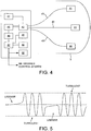
- Figure 5 is a line graph schematically illustrating a sensor signal developed by the processor 47 over time, based upon the interference between the reference and sensor light signals. Beginning at the left of the diagram, the flat region of the graph corresponds to periods in which the membrane is not moving. The phase difference between the sensor signal and the reference signal is therefore constant, and the line graph is flat. Gentle movement of the membrane under the influence of external atmospheric pressure will be reflected by small changes in phase and associated changes in the intensity of the resulting light signal due to the interference.
- the phase between the reference signal and the sensor signal will change and result in further changes in intensity. If the magnitude of the movement of the membrane is sufficiently large, a sinusoidal variation in the intensity of the light will be seen as the phase difference increases through complete phase oscillations. The sinusoidal variation will continue for the period in which the membrane is moving, and will reverse direction as the direction of movement of the membrane reverses.
- the time taken for the intensity to vary from peak to peak additionally indicates the time taken for the membrane to move half of the distance indicated by the wavelength of the light signal.
- the intensity graph of Figure 5 which is developed by the processor can therefore be used to give an indication of the air flow conditions across the surface of the blade. Turbulent air flow will result in buffeting of the blade and the sensor membrane, and the corresponding graph of intensity will indicate frequent and chaotic movements of the membrane. This will be characterised by many occurrences of sinusoidal variation of the signal, and relatively few periods where the intensity is essentially unchanging or is changing slowly. Further the sinusoidal variations themselves are likely to have higher frequencies of oscillation, indicating faster movement of the membrane than at other times.
- Laminar air flow or non-turbulent background conditions will result in little or less movement of the membrane.
- the intensity graph would therefore be characterised by more and longer periods of flat lines, gentle variations, or periods in which although a sinusoidal variation is seen, it has a long wavelength indicating that it is occurring relatively slowly.
- the flat line regions of the graph representing no movement of the membrane may or may not always indicate the same intensity of light.
- the rest position of the membrane may be largely determined at least in part by the membrane tension and the material of which the membrane is made, the instantaneous force exerted by the air flow will ultimately determine the instantaneous position.
- the processor 47 analyses the intensity of the light signals received at ADC 46, to determine the present quality of air flow across the blade. It may do this using any suitable mathematical processing techniques to determine the amount of variation in the light interference signal, such as that shown in Figure 5 . In other embodiments, it may use neural network techniques to develop a memory of the visual appearance of the intensity patterns for turbulent and laminar air flow, and determine the current air flow conditions by comparison with pre-developed model patterns. Such patterns may be stored in memory 49.
- the processor 47 has the further function of assessing the current operating performance of the wind turbine blades based on the results collected from the plurality of sensors 44 over time. It will be appreciated that a separate processor could be provided for this purpose, but that for the sake of simplicity in the present description, processor 47 will be assumed to perform both roles.
- the processor preferably takes continuous or periodic readings from the turbulence sensors 44 to develop a time-log of changes in the air flow over the blade.
- an intensity pattern such as that shown in Figure 5 needs to be built up over a minimum period of time. Assuming that the wind is blowing sufficiently strongly, a measurement period of a few second to a several minutes may be sufficient. Longer measurement periods however can provide a greater degree of certainty for the assessment.
- periodic measurements may for example only be required a limited number of times per day.
- the light sensors are activated for discrete periods of time, and subsequently deactivated when not required to be in use.
- the processor divides the continuous readings into discrete time windows for each sensor.
- the processor 47 receives the light intensity signal from each sensor for the measurement period, and stores this in memory 49 with an indication of the time period. Each signal is then analysed to determine whether or not it is characteristic of turbulent or laminar air flow, and the result of the determination logged. It will be appreciated that the result may be a discrete value, either a positive or a negative indication of turbulence, or may be a continuous value indicating the degree to which the air flow is turbulent.
- the blades and other wind turbine components will be largely free of dirt, but depending on the time of year, and climate conditions, ice may or may not have accumulated.
- the readings from the sensors 44 should largely indicate laminar flow. Nevertheless, particular sensors at particular times may indicate turbulent air flow, as a result of instantaneous and unpredictable variations in the air flow. Such indications would be sporadic and without pattern.
- the results from the sensors are logged and monitored by the processor to determine larger scale changes that are indicative of problems with the component. For example, if in normal operation three sensors on a blade surface component occasionally and sporadically indicate turbulent air flow but largely give a reading consistent with laminar air flow, then a change in the system to a persistent reading of turbulence from two or more sensors might indicate that the air flow across the blade has been affected by the build up of matter, and that action needs to be taken. Such a condition is illustrated in Figure 6 , where sensor time periods are indicated by columns and individual sensor readings indicated by rows. In this diagram, two sets of three sensors located on the windward and leeward sides of a wind turbine blade are depicted.
- the first four columns show an occasional turbulence detection from a sensor, but do not indicate any large scale trend.
- the columns after point A however show a permanent change to turbulent indications from the majority of sensors and are indicative of a problem with the blade condition.
- the processor may therefore detect such problems simply by counting the number of turbulence indications over a predetermined time period or window, say four or more. If a threshold count is passed, the processor issues an alarm indicating that attention is needed.
- the alarm function operates on a continuous basis such that if the turbulent conditions are no longer detected the alarm is cancelled.
- the turbulence sensors on the leeward side of the blade will return to largely indicating a normal condition.
- turbulence can be a result of the blade pitch and not necessarily accumulation of unwanted matter.
- the processor can be configured to test the determination by reducing the blade pitch and reducing the likelihood that the turbulence is due solely to the blade angle. If doing so results in a cancellation of the alarm signal, the blades may be pitched into the wind as before to resume operation.
- the processor 47 compares the results from one blade to those of another.
- Sub-optimal turbulence performance of one blade in comparison with the other blades may indicate that the mounting of the blade on the rotor hub needs adjustment, or that the blade is not performing as well, due to stress or other factors.
- the processor may, if persistent sub-optimal performance is detected, issue an alarm to draw attention to the blade condition.
- the sensor described above is relatively inexpensive to produce and is easy to mount.
- sensor systems comprising a large number of sensors can be installed relatively easily into both new and existing turbines.
- the membrane may be painted the same colour as the surrounding component surface to ensure that the visual appearance of the wind turbine is not impaired. Painting the area after mounting the sensor also has the effect that no moisture can enter the blade along the side of the sensor cavity 12 and 13 and blade 5.
- the ADC 46 and the turbulence detection part of the processor may be replaced by an analogue filter that passes the high frequencies associated with rapid deflection of the membrane 15, and a circuit that activates an output if the amount of signal within these frequencies exceeds a certain limit or rate of occurrence.
- the preferred device employs optical fibres as both light source and light detector in the sensor housing.
- opto-electronic devices such as light emitting diodes and photo detectors may be used directly inside the sensor housing, with appropriate electrical and signalling connections to a controller and power source. In certain embodiments it may of course be appropriate to install the control electronics and power systems locally or in the sensor itself.
Landscapes
- Physics & Mathematics (AREA)
- Engineering & Computer Science (AREA)
- General Physics & Mathematics (AREA)
- Sustainable Energy (AREA)
- Chemical & Material Sciences (AREA)
- Combustion & Propulsion (AREA)
- Mechanical Engineering (AREA)
- General Engineering & Computer Science (AREA)
- Life Sciences & Earth Sciences (AREA)
- Sustainable Development (AREA)
- Fluid Mechanics (AREA)
- Wind Motors (AREA)
- Indicating Or Recording The Presence, Absence, Or Direction Of Movement (AREA)
Claims (12)
- Sensorsystem zum Erfassen des Oberflächenzustands einer Windturbinenkomponente mit einem Hohlraum 13, umfassend:eine Vielzahl von Turbulenzsensoren 10, zum Ausgeben eines Ergebnisses, das turbulenten Luftstrom über einer Oberfläche der Windturbinenkomponente angibt;einen Speicher; undeinen Prozessor;wobei jeder Turbulenzsensor Folgendes umfasst:eine Sensormembran 15 zum Erfassen der Luftstromturbulenz über eine Oberfläche der Windturbinenkomponente, wobei die Sensormembran 15 integraler Bestandteil der Oberfläche ist und zumindest einen Teil des Hohlraums 13 abdeckt;eine Lichtquelle 16, die in dem Sensorhohlraum 13 angeordnet ist, zum Beleuchten der Oberfläche der Sensormembran 15 im Inneren des Hohlraums 13; undeinen Lichtdetektor, der in dem Hohlraum 13 angeordnet ist, zum Erfassen von Licht, das von der Oberfläche der Membran 15 reflektiert wird, und zum Bereitstellen eines Ergebnisses an einen Prozessor, wobei der Prozessor anhand des Ergebnisses einen Turbulenzwert für den Luftstrom über die Sensormembran ermittelt;wobei der Prozessor angepasst ist, einen Zustand der Komponentenoberfläche anhand des von den Turbulenzsensoren 10 empfangenen Ergebnisses zu ermitteln;wobei der Speicher angepasst ist, die von den Turbulenzsensoren 10 empfangenen Ergebnisse über einen Zeitraum aufzuzeichnen, und der Prozessor angepasst ist, einen Zustand der Komponentenoberfläche aufgrund einer Veränderung der Ergebnisse im Vergleich zu vergangenen Ergebnissen zu ermitteln; undwobei das Sensorsystem angepasst ist, die Anhäufung von Materie auf der Komponentenoberfläche durch Ermitteln dessen zu erfassen, ob eine vorbestimmte Anzahl der Turbulenzsensoren anhaltend Turbulenz anzeigt.
- Sensorsystem nach Anspruch 1, wobei die Lichtquelle 16 und der Lichtdetektor in dem Hohlraum 13 optische Fasern sind, die mit einer optoelektrischen Lichtquelle verbunden sind.
- Sensorsystem nach Anspruch 1 oder 2, umfassend einen Addierer zum Addieren von Licht, das von der Oberfläche der Membran 15 reflektiert wird, zu einem Referenzlichtsignal, um ein Interferenzmuster auszugeben, das eine Verdrängung der Membran 15 angibt.
- Sensorsystem nach Anspruch 3, wobei der Addierer einen Teilspiegel umfasst, der in dem Sensorhohlraum angeordnet ist, um einen Abschnitt des Lichts von der Lichtquelle zu dem Lichtdetektor zu reflektieren und das Referenzlichtsignal bereitzustellen.
- Sensorsystem nach einem der vorstehenden Ansprüche, wobei der Hohlraum 13 verschlossen ist.
- Sensorsystem nach Anspruch 5, wobei der Hohlraum 13 bis einem anderen Gas als Luft befüllt ist.
- Sensorsystem nach einem der vorstehenden Ansprüche, wobei die Sensormembran 15 aus einem anderen Material gebildet ist als die Oberfläche der Windturbinenkomponente.
- Sensorsystem nach Anspruch 3, umfassend einen Prozessor zum Analysieren der Variationen in dem Interferenzmuster über einen vorbestimmten Zeitraum, um zu ermitteln, ob der Luftstrom turbulent ist.
- Sensorsystem nach einem der vorstehenden Ansprüche, wobei die Windturbinenkomponente ein Windturbinenblatt ist.
- Sensorsystem nach Anspruch 9, umfassend eine Vielzahl von Sensoren 10 auf der windzugewandten und der windabgewandten Seite des Blattes.
- Sensorsystem nach Anspruch 9 oder 10, wobei der Prozessor die Ergebnisse von den Turbulenzsensoren 10 eines Windturbinenblattes mit jenen eines anderen vergleicht.
- Windturbine, umfassend das Sensorsystem nach einem der vorstehenden Ansprüche.
Applications Claiming Priority (3)
| Application Number | Priority Date | Filing Date | Title |
|---|---|---|---|
| US12297408P | 2008-12-16 | 2008-12-16 | |
| GB0822930A GB2466433B (en) | 2008-12-16 | 2008-12-16 | Turbulence sensor and blade condition sensor system |
| PCT/EP2009/008934 WO2010069534A1 (en) | 2008-12-16 | 2009-12-14 | Turbulence sensor and blade condition sensor system |
Publications (2)
| Publication Number | Publication Date |
|---|---|
| EP2374010A1 EP2374010A1 (de) | 2011-10-12 |
| EP2374010B1 true EP2374010B1 (de) | 2018-02-14 |
Family
ID=40326204
Family Applications (1)
| Application Number | Title | Priority Date | Filing Date |
|---|---|---|---|
| EP09801662.9A Not-in-force EP2374010B1 (de) | 2008-12-16 | 2009-12-14 | Turbulenzsensor und schaufelzustandssensorsystem |
Country Status (6)
| Country | Link |
|---|---|
| US (1) | US8712703B2 (de) |
| EP (1) | EP2374010B1 (de) |
| CN (1) | CN102282471A (de) |
| ES (1) | ES2662008T3 (de) |
| GB (1) | GB2466433B (de) |
| WO (1) | WO2010069534A1 (de) |
Families Citing this family (40)
| Publication number | Priority date | Publication date | Assignee | Title |
|---|---|---|---|---|
| US8120759B2 (en) | 2008-03-31 | 2012-02-21 | Vestas Wind Systems A/S | Optical transmission strain sensor for wind turbines |
| GB2461532A (en) | 2008-07-01 | 2010-01-06 | Vestas Wind Sys As | Sensor system and method for detecting deformation in a wind turbine component |
| GB2461566A (en) | 2008-07-03 | 2010-01-06 | Vestas Wind Sys As | Embedded fibre optic sensor for mounting on wind turbine components and method of producing the same. |
| GB2463696A (en) | 2008-09-22 | 2010-03-24 | Vestas Wind Sys As | Edge-wise bending insensitive strain sensor system |
| GB2466433B (en) | 2008-12-16 | 2011-05-25 | Vestas Wind Sys As | Turbulence sensor and blade condition sensor system |
| GB2472437A (en) | 2009-08-06 | 2011-02-09 | Vestas Wind Sys As | Wind turbine rotor blade control based on detecting turbulence |
| US7883313B2 (en) | 2009-11-05 | 2011-02-08 | General Electric Company | Active flow control system for wind turbine |
| US8321062B2 (en) * | 2009-11-05 | 2012-11-27 | General Electric Company | Systems and method for operating a wind turbine having active flow control |
| US8376704B2 (en) | 2009-11-05 | 2013-02-19 | General Electric Company | Systems and method of assembling an air distribution system for use in a rotor blade of a wind turbine |
| US8092172B2 (en) | 2009-11-05 | 2012-01-10 | General Electric Company | Method for operating a wind turbine with reduced blade fouling |
| US8221075B2 (en) | 2009-11-05 | 2012-07-17 | General Electric Company | Systems and method for operating a wind turbine having active flow control |
| US7931445B2 (en) | 2009-11-05 | 2011-04-26 | General Electric Company | Apparatus and method for cleaning an active flow control (AFC) system of a wind turbine |
| DE102010004662B4 (de) * | 2010-01-14 | 2014-12-24 | Siemens Aktiengesellschaft | Bor basierte Hartstoffbeschichtung einer Windkraftanlagenkomponente |
| GB2478600A (en) * | 2010-03-12 | 2011-09-14 | Vestas Wind Sys As | A wind energy power plant optical vibration sensor |
| US8327710B2 (en) * | 2010-07-29 | 2012-12-11 | General Electric Company | System for estimating a condition of non-conductive hollow structure exposed to a lightning strike |
| US8516899B2 (en) | 2010-10-06 | 2013-08-27 | Siemens Energy, Inc. | System for remote monitoring of aerodynamic flow conditions |
| US8267653B2 (en) | 2010-12-21 | 2012-09-18 | General Electric Company | System and method of operating an active flow control system to manipulate a boundary layer across a rotor blade of a wind turbine |
| JP5439357B2 (ja) * | 2010-12-28 | 2014-03-12 | 三菱重工業株式会社 | 工事時期選択装置及び工事時期選択方法 |
| CN103608653B (zh) * | 2011-04-13 | 2015-10-21 | 维斯塔斯风力系统集团公司 | 包括光学传感器系统的风力涡轮机 |
| WO2012149940A1 (en) * | 2011-05-04 | 2012-11-08 | Vestas Wind Systems A/S | A wind turbine optical wind sensor |
| US8265885B2 (en) * | 2011-06-24 | 2012-09-11 | General Electric Company | System and method for determining lifetime of wind turbine blade |
| WO2013097857A1 (en) * | 2011-12-29 | 2013-07-04 | Vestas Wind Systems A/S | A wind turbine and a method for determining the presence and/or thickness of an ice layer on a blade body of a wind turbine |
| US9759068B2 (en) * | 2013-02-28 | 2017-09-12 | General Electric Company | System and method for controlling a wind turbine based on identified surface conditions of the rotor blades |
| US9551321B2 (en) | 2013-06-26 | 2017-01-24 | General Electric Company | System and method for controlling a wind turbine |
| US9624905B2 (en) | 2013-09-20 | 2017-04-18 | General Electric Company | System and method for preventing excessive loading on a wind turbine |
| CN104595112B (zh) | 2013-10-30 | 2018-01-16 | 通用电气公司 | 风力涡轮机及评估其上叶片健康状态的方法 |
| US9631606B2 (en) | 2014-04-14 | 2017-04-25 | General Electric Company | System and method for thrust-speed control of a wind turbine |
| US20150300324A1 (en) * | 2014-04-18 | 2015-10-22 | Ashish Bhimrao Kharkar | Electromagnetic shielding of a strain gauge in a wind power installation |
| US9593670B2 (en) | 2014-04-30 | 2017-03-14 | General Electric Company | System and methods for reducing wind turbine noise |
| US9658124B2 (en) | 2014-11-05 | 2017-05-23 | General Electric Company | System and method for wind turbine operation |
| CN104819801B (zh) * | 2015-05-14 | 2018-06-08 | 中国空气动力研究与发展中心设备设计及测试技术研究所 | 一种风机叶片压力分布动态测量方法 |
| ES2834876T3 (es) * | 2017-02-20 | 2021-06-21 | Siemens Gamesa Renewable Energy As | Sistema para determinar el estado de suciedad de una pala de rotor de turbina eólica |
| US10634121B2 (en) | 2017-06-15 | 2020-04-28 | General Electric Company | Variable rated speed control in partial load operation of a wind turbine |
| DE102018112825A1 (de) * | 2018-05-29 | 2019-12-05 | fos4X GmbH | Sensoranordnung für eine Windkraftanlage |
| DE102019109908A1 (de) * | 2019-04-15 | 2020-10-15 | Wobben Properties Gmbh | Verfahren zum Bestimmen von Betriebsdaten einer Windenergieanlage sowie Vorrichtung und System dafür |
| EP3786449B1 (de) * | 2019-08-27 | 2022-05-04 | Nidec SSB Wind Systems GmbH | Druckmesssystem für windturbinenschaufeln |
| CN111121658B (zh) * | 2019-12-31 | 2021-04-20 | 沈阳航空航天大学 | 一种风力机气动性能实验下叶片变形测量方法 |
| FI129067B (en) | 2020-05-20 | 2021-06-15 | Teknologian Tutkimuskeskus Vtt Oy | Sensor, arrangement, use and method for estimating the angle of encounter |
| CN113250916B (zh) * | 2021-06-29 | 2022-08-30 | 中国华能集团清洁能源技术研究院有限公司 | 一种基于光干涉的风机塔筒倾斜监测装置及方法 |
| CN115450860B (zh) * | 2022-09-02 | 2023-06-30 | 广东金志利科技股份有限公司 | 一种风力发电机组用发电组机外壳 |
Citations (2)
| Publication number | Priority date | Publication date | Assignee | Title |
|---|---|---|---|---|
| GB2335108A (en) * | 1998-03-07 | 1999-09-08 | Sennheiser Electronic | An optical microphone |
| US7355720B1 (en) * | 2005-12-20 | 2008-04-08 | Sandia Corporation | Optical displacement sensor |
Family Cites Families (106)
| Publication number | Priority date | Publication date | Assignee | Title |
|---|---|---|---|---|
| SU577398A1 (ru) | 1976-07-07 | 1977-10-25 | Предприятие П/Я Х-5827 | Устройство дл контрол фотоэлектрических след щих систем |
| JPS5569006A (en) | 1978-11-21 | 1980-05-24 | Nippon Telegr & Teleph Corp <Ntt> | Strain measuring method for optical fiber |
| DE3106624A1 (de) | 1981-02-23 | 1982-09-16 | Dietrich, Reinhard, 8037 Olching | Regelungsverfahren fuer windenergieanlagen mit direkt aus der umstroemung des aerodynamisch wirksamen und auftrieberzeugenden profiles gewonnenen eingangssignalen |
| US4387993A (en) | 1981-06-25 | 1983-06-14 | Tsi Incorporated | Particle size measuring method and apparatus |
| GB2105846B (en) * | 1981-09-16 | 1985-10-02 | Nat Res Dev | Vortex flowmeter |
| DE3148867A1 (de) | 1981-12-10 | 1983-06-23 | Franz Josef Prof. Dr. 7507 Pfinztal Durst | Verfahren und vorrichtung zur bestimmung der geschwindigkeit lichtstreuender objekte, wie molekuele, kleine partikel o.dgl. |
| JPS58153107A (ja) | 1982-03-06 | 1983-09-12 | Hajime Kano | 粒子径・速度同時測定装置 |
| JPS60100707A (ja) | 1983-11-07 | 1985-06-04 | Hitachi Cable Ltd | 高感度干渉計 |
| CN1016275B (zh) * | 1985-06-20 | 1992-04-15 | 东机工株式会社 | 旋涡流量计 |
| US4671659A (en) | 1985-11-08 | 1987-06-09 | Martin Marietta Corporation | Fiber optic displacement sensor |
| US4681025A (en) * | 1986-04-22 | 1987-07-21 | Carty John J | Chimney stack having erodable liner with electrical generating capacity |
| DD253669A1 (de) | 1986-11-17 | 1988-01-27 | Verlade Transportanlagen | Dehnungstransformator zur messung von formaenderungen und/oder kraeften an bauteilen |
| JPH01206283A (ja) | 1988-02-13 | 1989-08-18 | Brother Ind Ltd | 光ヘテロダイン測定装置 |
| GB2224566A (en) | 1988-06-30 | 1990-05-09 | British Aerospace | An optical sensor for determining changes in a dimension and/or a temperature of an object |
| GB8826487D0 (en) | 1988-11-11 | 1988-12-14 | Health Lab Service Board | Optical determination of velocity |
| US4996419A (en) | 1989-12-26 | 1991-02-26 | United Technologies Corporation | Distributed multiplexed optical fiber Bragg grating sensor arrangeement |
| US5094527A (en) | 1990-05-14 | 1992-03-10 | Lockheed Corporation | Temperature compensated strain sensor for composite structures |
| DE4037077A1 (de) | 1990-11-22 | 1992-05-27 | Hilti Ag | Verfahren und einrichtung zur faseroptischen kraftmessung |
| US5201015A (en) | 1991-09-19 | 1993-04-06 | Litton Systems, Inc. | Conformal fiber optic strain sensor |
| US5250802A (en) | 1991-11-04 | 1993-10-05 | Teledyne Ryan Aeronautical, Division Of Teledyne Industries, Inc. | Fiber optic stress sensor for structural joints |
| JPH06117914A (ja) | 1992-10-06 | 1994-04-28 | Toshiba Corp | レーザドプラ方式振動計 |
| FR2707754B1 (fr) | 1993-07-12 | 1995-10-06 | Aerospatiale | Structure embarquée sur véhicule spatial, ayant des capteurs dimensionnels intégrés. |
| GB9317576D0 (en) | 1993-08-24 | 1993-10-06 | British Aerospace | Fibre optic damage detection system |
| GB9324333D0 (en) | 1993-11-26 | 1994-01-12 | Sensor Dynamics Ltd | Measurement of one or more physical parameters |
| US5488475A (en) | 1994-03-31 | 1996-01-30 | The United States Of America As Represented By The Secretary Of The Navy | Active fiber cavity strain sensor with temperature independence |
| FR2727203B1 (fr) | 1994-11-18 | 1996-12-13 | Commissariat Energie Atomique | Micro-systeme optique de type rosette de jauges de contraintes a guides dielectriques pour la mesure d'une contrainte longitudinale en structure plane |
| DE19524036C2 (de) | 1995-01-24 | 2002-04-11 | Fraunhofer Ges Forschung | Verfahren und Vorrichtung zur interferometrischen Erfassung der Form und/oder Formveränderung von Prüflingen |
| LV11389B (en) | 1995-07-19 | 1996-08-20 | Jurijs Roliks | Control method and device of wind power plant |
| LV11378B (en) | 1995-08-01 | 1996-08-20 | Nikolajs Levins | Control method and device of wind power plant's |
| GB9521957D0 (en) | 1995-10-26 | 1996-01-03 | Limited | Strain gauge |
| US5649035A (en) | 1995-11-03 | 1997-07-15 | Simula Inc. | Fiber optic strain gauge patch |
| US5633748A (en) | 1996-03-05 | 1997-05-27 | The United States Of America As Represented By The Secretary Of The Navy | Fiber optic Bragg grating demodulator and sensor incorporating same |
| JP3269396B2 (ja) | 1996-08-27 | 2002-03-25 | 松下電器産業株式会社 | 非水電解質リチウム二次電池 |
| US5973317A (en) | 1997-05-09 | 1999-10-26 | Cidra Corporation | Washer having fiber optic Bragg Grating sensors for sensing a shoulder load between components in a drill string |
| GB2326471B (en) | 1997-06-19 | 2001-05-30 | British Aerospace | A strain isolated optical fibre bragg grating sensor |
| ATE255219T1 (de) | 1998-09-04 | 2003-12-15 | Fiber Optic Sensors Fos Sa | Lichtwellenleiterverformungssensor |
| JP2983018B1 (ja) | 1998-09-30 | 1999-11-29 | エヌ・ティ・ティ・アドバンステクノロジ株式会社 | 光ファイバセンサ |
| WO2000023764A1 (en) | 1998-10-16 | 2000-04-27 | New Focus, Inc. | Interferometer for optical wavelength monitoring |
| JP3606067B2 (ja) | 1998-10-30 | 2005-01-05 | スズキ株式会社 | 振動測定方法および装置 |
| GB9824756D0 (en) | 1998-11-11 | 1999-01-06 | Europ Economic Community | A strain sensor and strain sensing apparatus |
| AU778263B2 (en) | 1998-12-04 | 2004-11-25 | Cidra Corporation | Strain-isolated optical temperature sensor |
| DE19923087B4 (de) | 1999-05-20 | 2004-02-26 | Eads Deutschland Gmbh | Vorrichtung zur Druck-, Schall- und Vibrationsmessung, sowie Verfahren zur Strömungsanalyse an Bauteiloberflächen |
| DE19927015A1 (de) | 1999-06-07 | 2000-12-14 | Zeiss Carl Jena Gmbh | Verfahren und Vorrichtung zur Bestimmung der Dicke und Wachstumsgeschwindigkeit einer Eisschicht |
| DK173607B1 (da) * | 1999-06-21 | 2001-04-30 | Lm Glasfiber As | Vindmøllevinge med system til afisning af lynbeskyttelse |
| KR100329042B1 (ko) | 1999-08-03 | 2002-03-18 | 윤덕용 | 광섬유 구조물 변형 감지시스템 |
| DK1230479T3 (da) | 1999-11-03 | 2005-01-10 | Vestas Wind Sys As | Fremgangsmåde til styring af en vindmölles drift samt vindmölle til anvendelse ved denne fremgangsmåde |
| CA2402675A1 (fr) | 2000-03-06 | 2001-09-13 | Fiber Optic Sensors-Fos Sa | Dispositif a fibre optique pour la mesure de contraintes |
| DE10011393A1 (de) * | 2000-03-09 | 2001-09-13 | Tacke Windenergie Gmbh | Regelungssystem für eine Windkraftanlage |
| JP2001296110A (ja) | 2000-04-17 | 2001-10-26 | Ntt Advanced Technology Corp | 貼り付け型光ファイバセンサ |
| US6747743B2 (en) | 2000-11-10 | 2004-06-08 | Halliburton Energy Services, Inc. | Multi-parameter interferometric fiber optic sensor |
| DE20021970U1 (de) | 2000-12-30 | 2001-04-05 | Igus Ingenieurgemeinschaft Umweltschutz Meß-und Verfahrenstechnik GmbH, 01099 Dresden | Einrichtung zur Überwachung des Zustandes von Rotorblättern an Windkraftanlagen |
| FR2823299B1 (fr) | 2001-04-04 | 2003-09-19 | Commissariat Energie Atomique | Extensometre a longue base, a fibre optique tendue et reseau de bragg, et procede de fabrication de cet extensometre |
| EP1249692A1 (de) | 2001-04-12 | 2002-10-16 | Fos Sàrl | Faseroptisches Gerät zur Spannungsmessung |
| DE10160522A1 (de) | 2001-12-05 | 2003-06-26 | Walter Mueller | Optisches Sensorsystem zur Erfassung von Eisbildungen |
| US7038190B2 (en) | 2001-12-21 | 2006-05-02 | Eric Udd | Fiber grating environmental sensing system |
| NO334515B1 (no) | 2002-03-13 | 2014-03-31 | Light Structures As | Fiberoptisk sensorpakke |
| JP2003302536A (ja) | 2002-04-12 | 2003-10-24 | Sumitomo Electric Ind Ltd | 光学素子 |
| DE20206704U1 (de) | 2002-04-27 | 2002-08-22 | Diwald, Werner, 17291 Ludwigsburg | Eissensor für Windenergieanlagen |
| CA2426711C (en) * | 2002-05-02 | 2009-11-17 | General Electric Company | Wind power plant, control arrangement for a wind power plant, and method for operating a wind power plant |
| US7246991B2 (en) | 2002-09-23 | 2007-07-24 | John Vanden Bosche | Wind turbine blade deflection control system |
| GB0302434D0 (en) | 2003-02-03 | 2003-03-05 | Sensor Highway Ltd | Interferometric method and apparatus for measuring physical parameters |
| GB2398841A (en) | 2003-02-28 | 2004-09-01 | Qinetiq Ltd | Wind turbine control having a Lidar wind speed measurement apparatus |
| DE10315676B4 (de) | 2003-04-07 | 2016-10-13 | Thomas Huth-Fehre | Sensor für Oberflächen |
| US6940185B2 (en) * | 2003-04-10 | 2005-09-06 | Advantek Llc | Advanced aerodynamic control system for a high output wind turbine |
| US20040252290A1 (en) * | 2003-06-10 | 2004-12-16 | Ferguson Gary W. | Optical strain gauge and methods of use including a wind measurement device |
| KR100488221B1 (ko) | 2003-09-08 | 2005-05-10 | 주식회사 파이버프로 | 광섬유 브래그 격자 센서 시스템 |
| US7781725B2 (en) | 2004-10-21 | 2010-08-24 | Mossman Guy E | Optical fiber based sensor system suitable for monitoring remote aqueous infiltration |
| US7245382B2 (en) | 2003-10-24 | 2007-07-17 | Optoplan As | Downhole optical sensor system with reference |
| FR2864202B1 (fr) | 2003-12-22 | 2006-08-04 | Commissariat Energie Atomique | Dispositif tubulaire instrumente pour le transport d'un fluide sous pression |
| US7268884B2 (en) | 2003-12-23 | 2007-09-11 | Optoplan As | Wavelength reference system for optical measurements |
| US7813598B2 (en) | 2004-01-23 | 2010-10-12 | Lm Glasfiber A/S | Device including a system adapted for use in temperature compensation of strain measurements in fibre-reinforced structures |
| EP1586854A3 (de) | 2004-04-15 | 2006-02-08 | Davidson Instruments | Interferometrischer Signalkonditionierer zur Messung der absoluten Länge von Spalten in einem fiberoptischen Fabry-Pérot-Interferometer |
| FR2870003B1 (fr) | 2004-05-04 | 2006-07-28 | Thales Sa | Dispositif de mesure de decalage en frequence par effet doppler |
| US7086834B2 (en) | 2004-06-10 | 2006-08-08 | General Electric Company | Methods and apparatus for rotor blade ice detection |
| US7059822B2 (en) * | 2004-06-30 | 2006-06-13 | General Electrick Company | Methods and apparatus for measuring wind turbine blade deflection |
| EP1635034B1 (de) | 2004-08-27 | 2009-06-03 | Schlumberger Holdings Limited | Sensor und Vermessungsvorrichtung zur Bestimmung des Biegeradius und der Form eines Rohrleitungs |
| GB2421075A (en) | 2004-12-09 | 2006-06-14 | Insensys Ltd | Optical-fibre interstice displacement sensor |
| JP4648403B2 (ja) * | 2004-12-14 | 2011-03-09 | アロイス・ヴォベン | 風力発電設備用のローターブレード |
| US20060285813A1 (en) | 2005-06-10 | 2006-12-21 | Ferguson Stephen K | Fiber anchoring method for optical sensors |
| US7476985B2 (en) * | 2005-07-22 | 2009-01-13 | Gamesa Innovation & Technology, S.L. | Method of operating a wind turbine |
| DK200501312A (da) * | 2005-09-21 | 2007-03-22 | Lm Glasfiber As | Fastgörelsesanordninger på vinge |
| US7342323B2 (en) | 2005-09-30 | 2008-03-11 | General Electric Company | System and method for upwind speed based control of a wind turbine |
| JP2007114072A (ja) | 2005-10-21 | 2007-05-10 | Miyazaki Tlo:Kk | Fbgを用いた歪み計測システム |
| US7303373B2 (en) | 2005-10-31 | 2007-12-04 | General Electric Company | Wind turbine systems, monitoring systems and processes for monitoring stress in a wind turbine blade |
| DE102005054594A1 (de) * | 2005-11-14 | 2007-05-16 | Daubner & Stommel Gbr | Rotorblatt für eine Windenergieanlage |
| GB2435689B (en) | 2006-03-02 | 2009-04-08 | Insensys Ltd | Structural monitoring |
| EP1994281B1 (de) | 2006-03-16 | 2013-05-22 | Vestas Wind Systems A/S | Verfahren und steuersystem zur verringerung von dauerbelastungen von komponenten einer windturbine, die einer asymmetrischen belastung der rotorebene ausgesetzt sind |
| US7356207B2 (en) | 2006-06-05 | 2008-04-08 | Honeywell International, Inc. | Method and system for adjusting the sensitivity of optical sensors |
| DE102006028167A1 (de) * | 2006-06-16 | 2007-12-20 | Daubner & Stommel Gbr Bau-Werk-Planung | Verfahren zum Betreiben einer zumindest einen fluiddynamischen Auftriebskörper aufweisenden Vorrichtung, insbesondere einer Windenergieanlage |
| GB2440954B (en) | 2006-08-18 | 2008-12-17 | Insensys Ltd | Structural monitoring |
| GB2440955A (en) | 2006-08-18 | 2008-02-20 | Insensys Ltd | Wind turbine blade monitoring |
| GB2440953B (en) | 2006-08-18 | 2009-09-30 | Insensys Ltd | Wind turbines |
| EP1911968A1 (de) | 2006-10-10 | 2008-04-16 | Ecotecnia Energias Renovables S.L. | Regelungssystem für eine Windenergieanlage sowie Verfahren hierzu |
| US7908923B2 (en) * | 2006-12-07 | 2011-03-22 | Siemens Aktiengesellschaft | Method of non-destructively testing a work piece and non-destructive testing arrangement |
| CN101636581B (zh) | 2007-02-19 | 2011-11-30 | 维斯塔斯风力系统有限公司 | 带有应变检测机构的风轮机叶片、风轮机、块状传感器单元及其使用 |
| EP2130009A2 (de) * | 2007-03-29 | 2009-12-09 | Vestas Wind Systems A/S | Verfahren zum untersuchen mindestens eines rotorflügels einer windturbine und untersuchungssystem für mindestens einen rotorflügel einer windturbine |
| US7909575B2 (en) * | 2007-06-25 | 2011-03-22 | General Electric Company | Power loss reduction in turbulent wind for a wind turbine using localized sensing and control |
| US7950901B2 (en) * | 2007-08-13 | 2011-05-31 | General Electric Company | System and method for loads reduction in a horizontal-axis wind turbine using upwind information |
| WO2009034379A2 (en) * | 2007-09-12 | 2009-03-19 | Bae Systems Plc | Fluid flow monitoring |
| EP2037212B1 (de) * | 2007-09-12 | 2015-12-30 | Siemens Aktiengesellschaft | Verfahren und Sensor zur Bestimmung einer Ablenkung oder Dehnung |
| US20090097976A1 (en) | 2007-10-15 | 2009-04-16 | General Electric Company | Active damping of wind turbine blades |
| US8002523B2 (en) * | 2007-10-26 | 2011-08-23 | Borden Saxon D | Turbine system and method for extracting energy from waves, wind, and other fluid flows |
| US8277185B2 (en) | 2007-12-28 | 2012-10-02 | General Electric Company | Wind turbine, wind turbine controller and method for controlling a wind turbine |
| US8408871B2 (en) * | 2008-06-13 | 2013-04-02 | General Electric Company | Method and apparatus for measuring air flow condition at a wind turbine blade |
| GB2466433B (en) | 2008-12-16 | 2011-05-25 | Vestas Wind Sys As | Turbulence sensor and blade condition sensor system |
| US8463085B2 (en) * | 2010-12-17 | 2013-06-11 | General Electric Company | Systems and methods for monitoring a condition of a rotor blade for a wind turbine |
-
2008
- 2008-12-16 GB GB0822930A patent/GB2466433B/en not_active Expired - Fee Related
-
2009
- 2009-12-14 EP EP09801662.9A patent/EP2374010B1/de not_active Not-in-force
- 2009-12-14 US US13/139,411 patent/US8712703B2/en not_active Expired - Fee Related
- 2009-12-14 ES ES09801662.9T patent/ES2662008T3/es active Active
- 2009-12-14 CN CN2009801545756A patent/CN102282471A/zh active Pending
- 2009-12-14 WO PCT/EP2009/008934 patent/WO2010069534A1/en active Application Filing
Patent Citations (2)
| Publication number | Priority date | Publication date | Assignee | Title |
|---|---|---|---|---|
| GB2335108A (en) * | 1998-03-07 | 1999-09-08 | Sennheiser Electronic | An optical microphone |
| US7355720B1 (en) * | 2005-12-20 | 2008-04-08 | Sandia Corporation | Optical displacement sensor |
Also Published As
| Publication number | Publication date |
|---|---|
| WO2010069534A1 (en) | 2010-06-24 |
| GB2466433B (en) | 2011-05-25 |
| ES2662008T3 (es) | 2018-04-05 |
| GB2466433A (en) | 2010-06-23 |
| US8712703B2 (en) | 2014-04-29 |
| US20110246094A1 (en) | 2011-10-06 |
| EP2374010A1 (de) | 2011-10-12 |
| GB0822930D0 (en) | 2009-01-21 |
| CN102282471A (zh) | 2011-12-14 |
Similar Documents
| Publication | Publication Date | Title |
|---|---|---|
| EP2374010B1 (de) | Turbulenzsensor und schaufelzustandssensorsystem | |
| EP2486270B1 (de) | Auf erkennung von turbulenzen basierende rotorblattsteuerung | |
| US9441614B2 (en) | Wind energy power plant equipped with an optical vibration sensor | |
| EP2697613B1 (de) | Windturbine mit einem optischen sensorsystem | |
| US10344740B2 (en) | Methods and systems for detecting sensor fault modes | |
| CA2627829C (en) | Pressure measurement device and method for determining wind force at wind energy installations | |
| ES2809172T3 (es) | Monitorización de eventos a través de combinación de señales | |
| EP2589943B1 (de) | Verfahren und Systeme zum Erkennen von Sensorfehlermodi | |
| US11448195B2 (en) | Sensor arrangement for a wind turbine | |
| EP3415753A2 (de) | Anomalieüberwachungsvorrichtung und anomalieüberwachungsverfahren für windpark | |
| US9753050B2 (en) | Wind turbine component having an optical fibre wind sensor | |
| CN114396364A (zh) | 一种风电叶片大尺度安全监测系统及方法 |
Legal Events
| Date | Code | Title | Description |
|---|---|---|---|
| PUAI | Public reference made under article 153(3) epc to a published international application that has entered the european phase |
Free format text: ORIGINAL CODE: 0009012 |
|
| 17P | Request for examination filed |
Effective date: 20110706 |
|
| AK | Designated contracting states |
Kind code of ref document: A1 Designated state(s): AT BE BG CH CY CZ DE DK EE ES FI FR GB GR HR HU IE IS IT LI LT LU LV MC MK MT NL NO PL PT RO SE SI SK SM TR |
|
| RAP1 | Party data changed (applicant data changed or rights of an application transferred) |
Owner name: VESTAS WIND SYSTEMS A/S |
|
| DAX | Request for extension of the european patent (deleted) | ||
| RAP1 | Party data changed (applicant data changed or rights of an application transferred) |
Owner name: VESTAS WIND SYSTEMS A/S |
|
| 17Q | First examination report despatched |
Effective date: 20160829 |
|
| GRAP | Despatch of communication of intention to grant a patent |
Free format text: ORIGINAL CODE: EPIDOSNIGR1 |
|
| RIC1 | Information provided on ipc code assigned before grant |
Ipc: G01P 13/00 20060101AFI20170712BHEP Ipc: F03D 7/00 20060101ALI20170712BHEP Ipc: F03D 17/00 20160101ALI20170712BHEP Ipc: G01M 9/06 20060101ALI20170712BHEP Ipc: F03D 80/40 20160101ALI20170712BHEP |
|
| INTG | Intention to grant announced |
Effective date: 20170802 |
|
| GRAS | Grant fee paid |
Free format text: ORIGINAL CODE: EPIDOSNIGR3 |
|
| RBV | Designated contracting states (corrected) |
Designated state(s): AT BE BG CH CY CZ DE DK EE ES FI FR GR HR HU IE IS IT LI LT LU LV MC MK MT NL NO PL PT RO SE SI SK SM TR |
|
| GRAA | (expected) grant |
Free format text: ORIGINAL CODE: 0009210 |
|
| AK | Designated contracting states |
Kind code of ref document: B1 Designated state(s): AT BE BG CH CY CZ DE DK EE ES FI FR GR HR HU IE IS IT LI LT LU LV MC MK MT NL NO PL PT RO SE SI SK SM TR |
|
| REG | Reference to a national code |
Ref country code: CH Ref legal event code: EP |
|
| REG | Reference to a national code |
Ref country code: IE Ref legal event code: FG4D |
|
| REG | Reference to a national code |
Ref country code: DE Ref legal event code: R096 Ref document number: 602009050766 Country of ref document: DE Ref country code: AT Ref legal event code: REF Ref document number: 970208 Country of ref document: AT Kind code of ref document: T Effective date: 20180315 |
|
| REG | Reference to a national code |
Ref country code: ES Ref legal event code: FG2A Ref document number: 2662008 Country of ref document: ES Kind code of ref document: T3 Effective date: 20180405 |
|
| REG | Reference to a national code |
Ref country code: NL Ref legal event code: MP Effective date: 20180214 |
|
| REG | Reference to a national code |
Ref country code: AT Ref legal event code: MK05 Ref document number: 970208 Country of ref document: AT Kind code of ref document: T Effective date: 20180214 |
|
| PG25 | Lapsed in a contracting state [announced via postgrant information from national office to epo] |
Ref country code: NL Free format text: LAPSE BECAUSE OF FAILURE TO SUBMIT A TRANSLATION OF THE DESCRIPTION OR TO PAY THE FEE WITHIN THE PRESCRIBED TIME-LIMIT Effective date: 20180214 Ref country code: HR Free format text: LAPSE BECAUSE OF FAILURE TO SUBMIT A TRANSLATION OF THE DESCRIPTION OR TO PAY THE FEE WITHIN THE PRESCRIBED TIME-LIMIT Effective date: 20180214 Ref country code: LT Free format text: LAPSE BECAUSE OF FAILURE TO SUBMIT A TRANSLATION OF THE DESCRIPTION OR TO PAY THE FEE WITHIN THE PRESCRIBED TIME-LIMIT Effective date: 20180214 Ref country code: FI Free format text: LAPSE BECAUSE OF FAILURE TO SUBMIT A TRANSLATION OF THE DESCRIPTION OR TO PAY THE FEE WITHIN THE PRESCRIBED TIME-LIMIT Effective date: 20180214 Ref country code: CY Free format text: LAPSE BECAUSE OF FAILURE TO SUBMIT A TRANSLATION OF THE DESCRIPTION OR TO PAY THE FEE WITHIN THE PRESCRIBED TIME-LIMIT Effective date: 20180214 Ref country code: NO Free format text: LAPSE BECAUSE OF FAILURE TO SUBMIT A TRANSLATION OF THE DESCRIPTION OR TO PAY THE FEE WITHIN THE PRESCRIBED TIME-LIMIT Effective date: 20180514 |
|
| PG25 | Lapsed in a contracting state [announced via postgrant information from national office to epo] |
Ref country code: GR Free format text: LAPSE BECAUSE OF FAILURE TO SUBMIT A TRANSLATION OF THE DESCRIPTION OR TO PAY THE FEE WITHIN THE PRESCRIBED TIME-LIMIT Effective date: 20180515 Ref country code: SE Free format text: LAPSE BECAUSE OF FAILURE TO SUBMIT A TRANSLATION OF THE DESCRIPTION OR TO PAY THE FEE WITHIN THE PRESCRIBED TIME-LIMIT Effective date: 20180214 Ref country code: LV Free format text: LAPSE BECAUSE OF FAILURE TO SUBMIT A TRANSLATION OF THE DESCRIPTION OR TO PAY THE FEE WITHIN THE PRESCRIBED TIME-LIMIT Effective date: 20180214 Ref country code: AT Free format text: LAPSE BECAUSE OF FAILURE TO SUBMIT A TRANSLATION OF THE DESCRIPTION OR TO PAY THE FEE WITHIN THE PRESCRIBED TIME-LIMIT Effective date: 20180214 Ref country code: BG Free format text: LAPSE BECAUSE OF FAILURE TO SUBMIT A TRANSLATION OF THE DESCRIPTION OR TO PAY THE FEE WITHIN THE PRESCRIBED TIME-LIMIT Effective date: 20180514 |
|
| PG25 | Lapsed in a contracting state [announced via postgrant information from national office to epo] |
Ref country code: IT Free format text: LAPSE BECAUSE OF FAILURE TO SUBMIT A TRANSLATION OF THE DESCRIPTION OR TO PAY THE FEE WITHIN THE PRESCRIBED TIME-LIMIT Effective date: 20180214 Ref country code: RO Free format text: LAPSE BECAUSE OF FAILURE TO SUBMIT A TRANSLATION OF THE DESCRIPTION OR TO PAY THE FEE WITHIN THE PRESCRIBED TIME-LIMIT Effective date: 20180214 Ref country code: PL Free format text: LAPSE BECAUSE OF FAILURE TO SUBMIT A TRANSLATION OF THE DESCRIPTION OR TO PAY THE FEE WITHIN THE PRESCRIBED TIME-LIMIT Effective date: 20180214 Ref country code: EE Free format text: LAPSE BECAUSE OF FAILURE TO SUBMIT A TRANSLATION OF THE DESCRIPTION OR TO PAY THE FEE WITHIN THE PRESCRIBED TIME-LIMIT Effective date: 20180214 |
|
| REG | Reference to a national code |
Ref country code: DE Ref legal event code: R097 Ref document number: 602009050766 Country of ref document: DE |
|
| PG25 | Lapsed in a contracting state [announced via postgrant information from national office to epo] |
Ref country code: DK Free format text: LAPSE BECAUSE OF FAILURE TO SUBMIT A TRANSLATION OF THE DESCRIPTION OR TO PAY THE FEE WITHIN THE PRESCRIBED TIME-LIMIT Effective date: 20180214 Ref country code: SM Free format text: LAPSE BECAUSE OF FAILURE TO SUBMIT A TRANSLATION OF THE DESCRIPTION OR TO PAY THE FEE WITHIN THE PRESCRIBED TIME-LIMIT Effective date: 20180214 Ref country code: CZ Free format text: LAPSE BECAUSE OF FAILURE TO SUBMIT A TRANSLATION OF THE DESCRIPTION OR TO PAY THE FEE WITHIN THE PRESCRIBED TIME-LIMIT Effective date: 20180214 Ref country code: SK Free format text: LAPSE BECAUSE OF FAILURE TO SUBMIT A TRANSLATION OF THE DESCRIPTION OR TO PAY THE FEE WITHIN THE PRESCRIBED TIME-LIMIT Effective date: 20180214 |
|
| REG | Reference to a national code |
Ref country code: CH Ref legal event code: PK Free format text: BERICHTIGUNGEN |
|
| PLBE | No opposition filed within time limit |
Free format text: ORIGINAL CODE: 0009261 |
|
| STAA | Information on the status of an ep patent application or granted ep patent |
Free format text: STATUS: NO OPPOSITION FILED WITHIN TIME LIMIT |
|
| RIC2 | Information provided on ipc code assigned after grant |
Ipc: F03D 7/00 20060101ALI20170712BHEP Ipc: G01P 13/00 20060101AFI20170712BHEP Ipc: F03D 80/40 20160101ALI20170712BHEP Ipc: G01M 9/06 20060101ALI20170712BHEP Ipc: F03D 17/00 20160101ALI20170712BHEP |
|
| 26N | No opposition filed |
Effective date: 20181115 |
|
| REG | Reference to a national code |
Ref country code: CH Ref legal event code: PK Free format text: BERICHTIGUNGEN |
|
| RIC2 | Information provided on ipc code assigned after grant |
Ipc: G01M 9/06 20060101ALI20170712BHEP Ipc: F03D 17/00 20160101ALI20170712BHEP Ipc: G01P 13/00 20060101AFI20170712BHEP Ipc: F03D 80/40 20160101ALI20170712BHEP Ipc: F03D 7/00 20060101ALI20170712BHEP |
|
| PG25 | Lapsed in a contracting state [announced via postgrant information from national office to epo] |
Ref country code: SI Free format text: LAPSE BECAUSE OF FAILURE TO SUBMIT A TRANSLATION OF THE DESCRIPTION OR TO PAY THE FEE WITHIN THE PRESCRIBED TIME-LIMIT Effective date: 20180214 |
|
| REG | Reference to a national code |
Ref country code: CH Ref legal event code: PL |
|
| PG25 | Lapsed in a contracting state [announced via postgrant information from national office to epo] |
Ref country code: LU Free format text: LAPSE BECAUSE OF NON-PAYMENT OF DUE FEES Effective date: 20181214 Ref country code: MC Free format text: LAPSE BECAUSE OF FAILURE TO SUBMIT A TRANSLATION OF THE DESCRIPTION OR TO PAY THE FEE WITHIN THE PRESCRIBED TIME-LIMIT Effective date: 20180214 |
|
| REG | Reference to a national code |
Ref country code: IE Ref legal event code: MM4A |
|
| REG | Reference to a national code |
Ref country code: BE Ref legal event code: MM Effective date: 20181231 |
|
| PG25 | Lapsed in a contracting state [announced via postgrant information from national office to epo] |
Ref country code: IE Free format text: LAPSE BECAUSE OF NON-PAYMENT OF DUE FEES Effective date: 20181214 |
|
| PG25 | Lapsed in a contracting state [announced via postgrant information from national office to epo] |
Ref country code: BE Free format text: LAPSE BECAUSE OF NON-PAYMENT OF DUE FEES Effective date: 20181231 |
|
| PG25 | Lapsed in a contracting state [announced via postgrant information from national office to epo] |
Ref country code: CH Free format text: LAPSE BECAUSE OF NON-PAYMENT OF DUE FEES Effective date: 20181231 Ref country code: LI Free format text: LAPSE BECAUSE OF NON-PAYMENT OF DUE FEES Effective date: 20181231 |
|
| PG25 | Lapsed in a contracting state [announced via postgrant information from national office to epo] |
Ref country code: MT Free format text: LAPSE BECAUSE OF NON-PAYMENT OF DUE FEES Effective date: 20181214 |
|
| PG25 | Lapsed in a contracting state [announced via postgrant information from national office to epo] |
Ref country code: TR Free format text: LAPSE BECAUSE OF FAILURE TO SUBMIT A TRANSLATION OF THE DESCRIPTION OR TO PAY THE FEE WITHIN THE PRESCRIBED TIME-LIMIT Effective date: 20180214 |
|
| PG25 | Lapsed in a contracting state [announced via postgrant information from national office to epo] |
Ref country code: PT Free format text: LAPSE BECAUSE OF FAILURE TO SUBMIT A TRANSLATION OF THE DESCRIPTION OR TO PAY THE FEE WITHIN THE PRESCRIBED TIME-LIMIT Effective date: 20180214 |
|
| PG25 | Lapsed in a contracting state [announced via postgrant information from national office to epo] |
Ref country code: HU Free format text: LAPSE BECAUSE OF FAILURE TO SUBMIT A TRANSLATION OF THE DESCRIPTION OR TO PAY THE FEE WITHIN THE PRESCRIBED TIME-LIMIT; INVALID AB INITIO Effective date: 20091214 Ref country code: MK Free format text: LAPSE BECAUSE OF NON-PAYMENT OF DUE FEES Effective date: 20180214 |
|
| PG25 | Lapsed in a contracting state [announced via postgrant information from national office to epo] |
Ref country code: IS Free format text: LAPSE BECAUSE OF FAILURE TO SUBMIT A TRANSLATION OF THE DESCRIPTION OR TO PAY THE FEE WITHIN THE PRESCRIBED TIME-LIMIT Effective date: 20180614 |
|
| PGFP | Annual fee paid to national office [announced via postgrant information from national office to epo] |
Ref country code: FR Payment date: 20201229 Year of fee payment: 12 |
|
| PGFP | Annual fee paid to national office [announced via postgrant information from national office to epo] |
Ref country code: ES Payment date: 20210122 Year of fee payment: 12 Ref country code: DE Payment date: 20210224 Year of fee payment: 12 |
|
| REG | Reference to a national code |
Ref country code: DE Ref legal event code: R119 Ref document number: 602009050766 Country of ref document: DE |
|
| PG25 | Lapsed in a contracting state [announced via postgrant information from national office to epo] |
Ref country code: DE Free format text: LAPSE BECAUSE OF NON-PAYMENT OF DUE FEES Effective date: 20220701 |
|
| PG25 | Lapsed in a contracting state [announced via postgrant information from national office to epo] |
Ref country code: FR Free format text: LAPSE BECAUSE OF NON-PAYMENT OF DUE FEES Effective date: 20211231 |
|
| REG | Reference to a national code |
Ref country code: ES Ref legal event code: FD2A Effective date: 20230306 |
|
| PG25 | Lapsed in a contracting state [announced via postgrant information from national office to epo] |
Ref country code: ES Free format text: LAPSE BECAUSE OF NON-PAYMENT OF DUE FEES Effective date: 20211215 |