EP2372233A2 - Lighting apparatus - Google Patents
Lighting apparatus Download PDFInfo
- Publication number
- EP2372233A2 EP2372233A2 EP20110157901 EP11157901A EP2372233A2 EP 2372233 A2 EP2372233 A2 EP 2372233A2 EP 20110157901 EP20110157901 EP 20110157901 EP 11157901 A EP11157901 A EP 11157901A EP 2372233 A2 EP2372233 A2 EP 2372233A2
- Authority
- EP
- European Patent Office
- Prior art keywords
- light
- optical units
- lighting apparatus
- optical unit
- light emitting
- Prior art date
- Legal status (The legal status is an assumption and is not a legal conclusion. Google has not performed a legal analysis and makes no representation as to the accuracy of the status listed.)
- Withdrawn
Links
Images


Classifications
-
- F—MECHANICAL ENGINEERING; LIGHTING; HEATING; WEAPONS; BLASTING
- F21—LIGHTING
- F21V—FUNCTIONAL FEATURES OR DETAILS OF LIGHTING DEVICES OR SYSTEMS THEREOF; STRUCTURAL COMBINATIONS OF LIGHTING DEVICES WITH OTHER ARTICLES, NOT OTHERWISE PROVIDED FOR
- F21V29/00—Protecting lighting devices from thermal damage; Cooling or heating arrangements specially adapted for lighting devices or systems
- F21V29/50—Cooling arrangements
- F21V29/51—Cooling arrangements using condensation or evaporation of a fluid, e.g. heat pipes
-
- F—MECHANICAL ENGINEERING; LIGHTING; HEATING; WEAPONS; BLASTING
- F21—LIGHTING
- F21S—NON-PORTABLE LIGHTING DEVICES; SYSTEMS THEREOF; VEHICLE LIGHTING DEVICES SPECIALLY ADAPTED FOR VEHICLE EXTERIORS
- F21S8/00—Lighting devices intended for fixed installation
- F21S8/08—Lighting devices intended for fixed installation with a standard
- F21S8/085—Lighting devices intended for fixed installation with a standard of high-built type, e.g. street light
- F21S8/086—Lighting devices intended for fixed installation with a standard of high-built type, e.g. street light with lighting device attached sideways of the standard, e.g. for roads and highways
-
- F—MECHANICAL ENGINEERING; LIGHTING; HEATING; WEAPONS; BLASTING
- F21—LIGHTING
- F21V—FUNCTIONAL FEATURES OR DETAILS OF LIGHTING DEVICES OR SYSTEMS THEREOF; STRUCTURAL COMBINATIONS OF LIGHTING DEVICES WITH OTHER ARTICLES, NOT OTHERWISE PROVIDED FOR
- F21V15/00—Protecting lighting devices from damage
- F21V15/01—Housings, e.g. material or assembling of housing parts
-
- F—MECHANICAL ENGINEERING; LIGHTING; HEATING; WEAPONS; BLASTING
- F21—LIGHTING
- F21V—FUNCTIONAL FEATURES OR DETAILS OF LIGHTING DEVICES OR SYSTEMS THEREOF; STRUCTURAL COMBINATIONS OF LIGHTING DEVICES WITH OTHER ARTICLES, NOT OTHERWISE PROVIDED FOR
- F21V19/00—Fastening of light sources or lamp holders
- F21V19/001—Fastening of light sources or lamp holders the light sources being semiconductors devices, e.g. LEDs
-
- F—MECHANICAL ENGINEERING; LIGHTING; HEATING; WEAPONS; BLASTING
- F21—LIGHTING
- F21V—FUNCTIONAL FEATURES OR DETAILS OF LIGHTING DEVICES OR SYSTEMS THEREOF; STRUCTURAL COMBINATIONS OF LIGHTING DEVICES WITH OTHER ARTICLES, NOT OTHERWISE PROVIDED FOR
- F21V29/00—Protecting lighting devices from thermal damage; Cooling or heating arrangements specially adapted for lighting devices or systems
- F21V29/50—Cooling arrangements
- F21V29/70—Cooling arrangements characterised by passive heat-dissipating elements, e.g. heat-sinks
- F21V29/74—Cooling arrangements characterised by passive heat-dissipating elements, e.g. heat-sinks with fins or blades
- F21V29/75—Cooling arrangements characterised by passive heat-dissipating elements, e.g. heat-sinks with fins or blades with fins or blades having different shapes, thicknesses or spacing
-
- F—MECHANICAL ENGINEERING; LIGHTING; HEATING; WEAPONS; BLASTING
- F21—LIGHTING
- F21V—FUNCTIONAL FEATURES OR DETAILS OF LIGHTING DEVICES OR SYSTEMS THEREOF; STRUCTURAL COMBINATIONS OF LIGHTING DEVICES WITH OTHER ARTICLES, NOT OTHERWISE PROVIDED FOR
- F21V29/00—Protecting lighting devices from thermal damage; Cooling or heating arrangements specially adapted for lighting devices or systems
- F21V29/50—Cooling arrangements
- F21V29/70—Cooling arrangements characterised by passive heat-dissipating elements, e.g. heat-sinks
- F21V29/74—Cooling arrangements characterised by passive heat-dissipating elements, e.g. heat-sinks with fins or blades
- F21V29/76—Cooling arrangements characterised by passive heat-dissipating elements, e.g. heat-sinks with fins or blades with essentially identical parallel planar fins or blades, e.g. with comb-like cross-section
-
- F—MECHANICAL ENGINEERING; LIGHTING; HEATING; WEAPONS; BLASTING
- F21—LIGHTING
- F21V—FUNCTIONAL FEATURES OR DETAILS OF LIGHTING DEVICES OR SYSTEMS THEREOF; STRUCTURAL COMBINATIONS OF LIGHTING DEVICES WITH OTHER ARTICLES, NOT OTHERWISE PROVIDED FOR
- F21V5/00—Refractors for light sources
- F21V5/04—Refractors for light sources of lens shape
-
- F—MECHANICAL ENGINEERING; LIGHTING; HEATING; WEAPONS; BLASTING
- F21—LIGHTING
- F21K—NON-ELECTRIC LIGHT SOURCES USING LUMINESCENCE; LIGHT SOURCES USING ELECTROCHEMILUMINESCENCE; LIGHT SOURCES USING CHARGES OF COMBUSTIBLE MATERIAL; LIGHT SOURCES USING SEMICONDUCTOR DEVICES AS LIGHT-GENERATING ELEMENTS; LIGHT SOURCES NOT OTHERWISE PROVIDED FOR
- F21K9/00—Light sources using semiconductor devices as light-generating elements, e.g. using light-emitting diodes [LED] or lasers
- F21K9/20—Light sources comprising attachment means
-
- F—MECHANICAL ENGINEERING; LIGHTING; HEATING; WEAPONS; BLASTING
- F21—LIGHTING
- F21K—NON-ELECTRIC LIGHT SOURCES USING LUMINESCENCE; LIGHT SOURCES USING ELECTROCHEMILUMINESCENCE; LIGHT SOURCES USING CHARGES OF COMBUSTIBLE MATERIAL; LIGHT SOURCES USING SEMICONDUCTOR DEVICES AS LIGHT-GENERATING ELEMENTS; LIGHT SOURCES NOT OTHERWISE PROVIDED FOR
- F21K9/00—Light sources using semiconductor devices as light-generating elements, e.g. using light-emitting diodes [LED] or lasers
- F21K9/60—Optical arrangements integrated in the light source, e.g. for improving the colour rendering index or the light extraction
- F21K9/68—Details of reflectors forming part of the light source
-
- F—MECHANICAL ENGINEERING; LIGHTING; HEATING; WEAPONS; BLASTING
- F21—LIGHTING
- F21S—NON-PORTABLE LIGHTING DEVICES; SYSTEMS THEREOF; VEHICLE LIGHTING DEVICES SPECIALLY ADAPTED FOR VEHICLE EXTERIORS
- F21S2/00—Systems of lighting devices, not provided for in main groups F21S4/00 - F21S10/00 or F21S19/00, e.g. of modular construction
- F21S2/005—Systems of lighting devices, not provided for in main groups F21S4/00 - F21S10/00 or F21S19/00, e.g. of modular construction of modular construction
-
- F—MECHANICAL ENGINEERING; LIGHTING; HEATING; WEAPONS; BLASTING
- F21—LIGHTING
- F21W—INDEXING SCHEME ASSOCIATED WITH SUBCLASSES F21K, F21L, F21S and F21V, RELATING TO USES OR APPLICATIONS OF LIGHTING DEVICES OR SYSTEMS
- F21W2131/00—Use or application of lighting devices or systems not provided for in codes F21W2102/00-F21W2121/00
- F21W2131/10—Outdoor lighting
- F21W2131/103—Outdoor lighting of streets or roads
-
- F—MECHANICAL ENGINEERING; LIGHTING; HEATING; WEAPONS; BLASTING
- F21—LIGHTING
- F21Y—INDEXING SCHEME ASSOCIATED WITH SUBCLASSES F21K, F21L, F21S and F21V, RELATING TO THE FORM OR THE KIND OF THE LIGHT SOURCES OR OF THE COLOUR OF THE LIGHT EMITTED
- F21Y2115/00—Light-generating elements of semiconductor light sources
- F21Y2115/10—Light-emitting diodes [LED]
Definitions
- Embodiments described herein relate generally to a lighting apparatus.
- a lighting apparatus lighting apparatus is sometimes constructed so that the light irradiation directions of respective LED modules can be adjusted.
- One way of adjusting the light irradiation directions is to adjust a mounting angle of the relevant LED module that is arranged on the apparatus main body. When using this way, the lighting apparatus does not include a reflecting mirror.
- the lighting apparatus includes an optical unit and a body.
- the Optical unit includes a light emitting module that has a light emitting element, a reflector that controls distribution of light from the light emitting module, and a unit supporting member that supports the light emitting module and the reflector.
- a plurality of optical units are mounted to the apparatus body such that each optical unit is detachable.
- the body includes an irradiating portion that has an opening through which the optical units irradiate light.
- Fig. 2 is an external perspective view when a state in which an lighting apparatus according to one embodiment of the present invention is arranged on a pole (support column) is viewed from underneath.
- Fig. 3 is an external perspective view when the lighting apparatus according to one embodiment of the present invention is viewed from overhead.
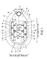
- Fig. 4 is a front view of the lighting apparatus according to one embodiment of the present invention.
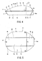
- Fig. 5 is a plan view of the lighting apparatus according to one embodiment of the present invention.
- an lighting apparatus 1 can be used, for example, as a road light or the like on a road such as a highway or an ordinary road.
- the lighting apparatus 1 is arranged at, for example, a height of approximately 10 meters above ground by a pole 2 comprising a hollow circular column or a hollow angular column or the like as a support column.
- the pole 2 for example, is firmly erected above the ground at the outer side of an edge in the width direction of a road such as a highway, and a plurality of the poles 2 are erected at a required pitch in the longitudinal direction of the road.
- the lighting apparatus 1 has an apparatus main body A.
- the apparatus main body A is constituted by hermetically closing an upper end 3d of an opening of a case main body 3 by fixing a top cover 4 that is one example of a cover to an open end of the upper surface in the drawing of the case main body 3 by screwing the top cover 4 to the open end or the like.
- a planar shape of the top cover 4 is formed in an approximately oblong shape by, for example, a die-cast aluminum material.
- the top cover 4 is formed so that a length W thereof along a width direction (the left-to-right direction in Fig. 4 and Fig. 5 ) of a road (not shown in the drawings) that is one example of an illumination object is longer than a length 1 along a longitudinal direction (vertical direction in Fig. 4 and Fig. 5 ) of the road.
- the upper surface of the top cover 4 in the drawings has a curved surface 4b which protrudes outward in a manner in which an approximately center section thereof is an apex 4a.
- a pair of projecting portions 4c and 4d at the front and rear of an outward convexity are integrally coupled in the longitudinal direction of the top cover 4.
- the projecting portions 4c and 4d are arranged in an approximately parallel condition with a required space therebetween in the width direction of the top cover 4.
- a band-shaped concave portion 4e that is recessed in the shape of a concave arc on the inner side is integrally coupled between the projecting portions 4c and 4d.
- the concave arc-shaped concave portion 4e is integrally coupled to a front end portion (left end portion in Fig. 4 and Fig. 5 ) 4f and a rear end portion (right end portion in Fig. 4 and Fig. 5 ) 4g by downward inclined planes 4h and 4i which are formed as curved surfaces that gradually descend from the center section 4a of the top cover 4 towards the front end portion 4f and the rear end portion 4g, respectively. More specifically, the outer surface of the top cover 4 is formed in a streamline shape that reduces air resistance when external air flows in the longitudinal direction and the width direction as shown by the arrows in Fig. 3 .
- the rear end of the rear end portion 4g of the top cover 4 is rotatably attached to an upper end portion of the rear end (right end in Fig. 4 ) of the case main body 3.
- the top cover 4 is formed as an opening/closing cover that can open and close in the direction of the white arrow in Fig. 4 .
- An electricity chamber 3a is formed inside the rear end portion (right end portion in Fig. 4 ) of the case main body 3 below the opening/closing cover 4g in Fig. 4 .
- the electricity chamber 3a is partitioned from a light source chamber 3c, described later, by a partitioning wall 3b indicated by a dashed line in Fig. 4 .
- a power source terminal (omitted from the drawings), a power source line that is connected to the power source terminal, and one end of a lighting control line are housed in the electricity chamber 3a in a watertight manner.
- a pole coupling portion 3ma that has a lateral hole for pole insertion 3m into which a distal end portion of a curved pole 2a shown in Fig. 14 is inserted and fixed is formed in the rear end wall of the case main body 3 that is the rear end wall of the electricity chamber 3a.
- the case main body 3 that has a polygonal cylindrical shape in which an opening is formed in the upper and lower ends in the drawing is detachably coupled by screwing to a lower end of an opening in the drawing of the top cover 4.
- a planar shape of an upper end portion 3d that is coupled with the top cover 4 is formed in a polygonal, flat cylindrical shape that is formed in an approximately oblong form that is the same form and same size as the oblong form of the planar shape of the top cover 4.
- a side surface 3e is formed in an inclined plane that gradually decreases towards the lower end 3f in the drawing.
- a large opening portion (omitted from the drawings) that passes through almost the entire surface of the upper end in the drawings of the light source chamber 3c is formed in the upper end portion 3d of the case main body 3.
- Fig. 1 is a bottom view of the lower end 3f of the case main body 3.
- a pole coupling portion 3i that has a vertical hole for pole insertion 3h into which, for example, a distal end portion of the pole 2 that has a straight bar shape that is shown in Fig. 2 is inserted and fixed is formed in the lower end portion 3f of a rear end portion (right end in Fig. 1 ) 3g on the electricity chamber 3a side thereof.
- a polygonal opening 3k having a shape of a horizontally-long rectangle in which each corner portion has been chamfered is formed on a front end portion (left end in Fig. 1 ) 3j side of the case main body 3.
- a translucent plate 5 comprising tempered glass that is one example of a translucent body is arranged in the opening 3k to seal the light source chamber 3c in a watertight and airtight manner.
- a plurality of LED optical units 6, 6, ... are aligned in a plurality of rows, for example, in Fig. 1 , four horizontal rows, and housed inside the light source chamber 3c.
- a required number, for example, five, of the LED optical units 6, 6, ... are symmetrically arranged on the left and right sides (top and bottom in Fig. 1 ), respectively, taking a central axis O that passes through the center of the four rows in the front-to-rear direction (the left-to-right direction in Fig. 1 ) of the case main body 3 as an axis of symmetry.
- the LED optical units 6, 6, ... on each side are, for example, arranged so that a required number, for example, two, of the LED optical units 6, 6, ... are arranged in parallel in the axial direction of the central axis O on an inner side "in” (central axis O side) of the array, and a required number, for example, three, of the LED optical units 6, 6, ... are arranged in parallel in the axial direction of the central axis O on an outer side "out” thereof.
- a required number for example, two
- central axis O side central axis O side
- each LED optical unit 6in as a first one of the plurality of the optical units 6 of the array on the inner side is disposed above, that is, at a higher position than (upper level), each LED optical unit 6out as a second one of the plurality of the optical units 6 of the array on the outer side.
- each LED optical unit 6in on the inner side is fixed in an inclined state so that a light axis La of the irradiation light thereof is at a required angle ⁇ a (for example, 50°) with respect to the surface of the translucent plate 5.
- each LED optical unit 6out on the outer side is fixed in an inclined state so that a light axis Lb of the irradiation light thereof is at a required angle ⁇ b (for example, 60°) with respect to the surface of the translucent plate 5.
- each LED optical unit 6 has an LED (light emitting diode) module 6a, a ceramic substrate 6b that is an example of a support substrate thereof, an upper and lower pair of flat mirrors 6c and 6d in Fig. 10 as a first reflective surface, a left and right pair of side curved mirrors 6e and 6f in Fig. 10 as a second reflective surface, and a reflecting tube 6i that is constructed as a trumpet-shaped angular cylindrical body in which the four mirrors 6c to 6f are unified or joined in an integrated manner.
- the reflecting tube 6i has a rectangular irradiation opening 6g that expands in a trumpet shape, and a bottom portion 6j whose diameter contracts in a trumpet shape on the opposite side in the axial direction thereof.
- the LED module 6a includes a COB (chip on board) type pseudo-white (blue-yellow system) LED bare chip 6ab as a light emitting element. More specifically, the LED module 6a includes a required number (for example, 196) of LED bare chips 6ab that emit blue light.
- the LED bare chips 6ab are directly mounted on a printed circuit board on which a circuit is formed, and arranged in a plurality of rows (14 rows, for example) and a plurality of columns (14 columns, for example). Subsequently, a resin containing phosphors that emit yellow light is applied onto the LED bare chips 6ab, the resulting structure is sealed by a silicone resin.
- the LED module 6a constructed in this manner is adhered by, for example, a silicone resin or the like on an approximately center section of a front face 6bc of the ceramic substrate 6b.
- a back side end portion of the ceramic substrate 6b is fitted inside a fitting opening portion 9k of a unit support plate 9 as a unit supporting member.
- the LED module 6a is adhered to the ceramic substrate 6b so that, in this fitted state, a light emitting surface 6aa of the LED module 6a is caused to protrude somewhat more upward in the drawing of Fig. 11A , that is, more frontward, than an inner bottom face 6jc of a bottom portion 6j on the contracted diameter side of the reflecting tube 6i so as to be exposed to outside.
- Fig. 11B is a longitudinal sectional view that illustrates a modification example of positioning of the ceramic substrate 6b shown in Fig. 11A .
- the front face 6bc of the upper surface in the figure of the ceramic substrate 6b may be configured to be approximately matched and be flush with a front face 9a of the unit support plate 9.
- the left and right pair of side curved mirrors 6e and 6f in the drawing are formed, for example, by curvedly forming a flat plate of aluminum or the like at a required angle and then forming the inner surface thereof as a reflective surface such as a mirror surface. Further, the curved reflective surface is formed so as to gradually expand towards both sides in the width direction of the road that is the illumination object.
- the reflecting tube 6i mainly controls the light distribution of light irradiated from the LED module 6a in the width direction of the road. More specifically, each of the LED optical units 6, 6, ... mainly controls the light distribution characteristics in the road width direction along the axial direction of the central axis O as shown in Fig.
- portions represented by a plurality of parallel vertical lines of each of the side curved mirrors 6e and 6f in Fig. 1 indicate the respective curved inner surfaces (that is, the reflective surfaces) of each of the side curved mirrors 6e and 6f.
- the upper and lower pair of flat mirrors 6c and 6d made of aluminum are joined in an integrated manner to the left and right pair of side curved mirrors 6e and 6f as shown in Fig. 12 and Fig. 13 to thereby form the reflecting tube 6i as a bottomed, trumpet-shaped angular cylindrical body that gradually expands towards an illumination opening 6g.
- the trumpet-shaped reflecting tube 6i forms a fitting opening portion 6k that interfits with the aforementioned ceramic substrate 6b on a center section of a bottom portion 6j on the contracted diameter side of the reflecting tube 6i.
- the ceramic substrate 6b is accommodated inside the fitting opening portion 6k. When the ceramic substrate 6b is accommodated therein, as shown in Figs.
- a front face 6bc of the ceramic substrate 6b is approximately flush with an inner surface 6jc of the bottom portion 6j of the reflecting tube 6i.
- a reflective surface such as a mirror surface is formed on the inner surface of the upper and lower pair of flat mirrors 6c and 6d, and the pair of flat mirrors 6c and 6d are arranged side by side in an approximately parallel manner with a required clearance therebetween in the vertical direction in the drawings.
- the upper and lower pair of flat mirrors 6c and 6d do not control light irradiated to outside from the irradiation opening 6g so as to magnify the irradiated light.
- heat dissipation holes h and h are formed in the vicinity of the LED module 6a in the upper and lower pair of flat mirrors 6c and 6d, respectively.
- the flat and side mirrors 6c to 6f are configured so that primary reflected light converges at a height of approximately 7 meters above ground when the apparatus main body A is arranged at a height of approximately 10 meters above ground by means of the pole 2.
- the back surface of the ceramic substrate 6b is fitted inside the fitting opening portion 9k formed on the front face 9a of the unit support plate 9 that is formed in the shape of a rectangular flat plate that is made of a metal such as aluminum that is shown in Fig. 9 , Figs. 11A and 11B , Fig. 12, and Fig. 13 .
- the front face of the ceramic substrate 6b is elastically supported by free ends of an upper and lower pair of plate springs 8a and 8b that are an example of a presser.
- An end on a side opposite to the free end of the plate springs 8a and 8b is fixed by screwing to the unit support plate 9. More specifically, the ceramic substrate 6b is elastically sandwiched in the thickness direction by the upper and lower pair of plate springs 8a and 8b and the unit support plate 9.
- Slits 8aa and 8ba that open at an inner end and extend in the vertical direction in Fig. 10 are formed in the protruding end portions, respectively.
- Small engagement protrusions 6ba and 6bb formed in a vertically long rectangular shape are provided in a protruding condition at the upper end and lower end of the front face of the ceramic substrate 6b, respectively.
- reference symbol 6h denotes a power supply connector that is electrically and detachably connected to the LED module 6a.
- the connector 6h is electrically connected to a power source terminal inside the electricity chamber 3a by a lead wire 1.
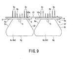
- a plurality of heat dissipation fins 9c, 9c, ... made of a metal such as aluminum are formed on a back face 9b of the unit support plate 9 in the LED optical unit 6.
- the outward protruding length of the heat dissipation fins 9c, 9c, ... may be the same as each other or, as shown in Fig. 9 and Fig. 13 , the outward protruding length of several of the heat dissipation fins 9c, 9c, ... on the inner side in the parallel arrangement direction may be shorter than the outward protruding length of the heat dissipation fins 9c, 9c, ... on the outer side.
- a plurality of the LED optical units 6 that are constructed in this manner are detachably attached by bolts or screws S or the like to a unit mounting plate 10.
- the unit mounting plate 10 is formed in a band-plate shape.
- a rectangular insertion hole 10a through which the plurality of heat dissipation fins 9c, 9c, ... are inserted is formed in the plate thickness direction of the unit mounting plate 10.
- the support plate 9 of the LED optical unit 6 is detachably fixed by a screw S to the unit mounting plate 10 in a state in which the plurality of heat dissipation fins 9c, 9c, ... are inserted through the insertion hole 10a.
- the unit mounting plates 10 for example, two of the inner side LED optical units 6in are arranged side by side and, for example, three of the outer side LED optical units 6out are arranged side by side.
- the unit mounting plates 10 are fixed at required places on the inner surface of the aforementioned top cover 4.
- all of the LED optical units 6, 6, ... are detachably fixed to the inner surface of the top cover 4.
- at least one part of the unit support plate 9 of the LED optical units 6, 6, ... is brought in contact directly with the inner surface of the top cover 4 or is brought in contact with the inner surface of the top cover 4 through a heat dissipating body such as a metal plate with excellent heat dissipation properties or a heat pipe to thereby enhance the heat dissipation properties of the lighting apparatus 1.
- a plurality of power source systems for example, two power source systems, are provided at a part of the LED optical units 6, 6, ... that are constructed in the above manner.
- the power source systems are electrically connected to the LED optical units 6, 6, ... so that, for example, in a case where a malfunction such as non-lighting occurs, it is possible to ensure bilateral symmetry when taking the central axis O of the remaining LED optical units 6, 6, ... that are irradiating light as the axis of symmetry.
- the LED optical units 6, 6, ... can be turned on to irradiate light by the remaining power source system, or if the LED optical units 6, 6, ... are already irradiating light, that lighting can be maintained.
- the plurality of power source systems may also be connected to the LED optical units 6, 6, ... so as to maintain the bilateral symmetry of the lighting of the LED optical units 6, 6, ... around the central axis O as the axis of symmetry.
- a configuration may be adopted in which two power source systems are provided, and one of the power source systems is connected to each of the four inner side LED optical units 6in, 6in, ..., and the other power source system is connected to each of the six inner side LED optical units 6out, 6out, ....
- this configuration even if one of the power source systems is cut off, either one of the inner side and outer side LED optical units 6in, 6out, ... can be caused to irradiate light and, furthermore, the bilateral symmetry can be maintained when irradiating light.
- the power source lines of the plurality of systems are connected to a secondary side of a power source terminal block inside the electricity chamber 3a of the case main body 3.
- An unshown primary-side power source line is electrically connected to the primary side of the power source terminal bock.
- the primary side power source line is passed through the inside of the hollow pole 2 and electrically connected to an unshown power supply apparatus.
- the power supply apparatus includes a control apparatus (not shown in the drawings) that controls a lighting circuit of the LED optical units 6, 6, ... to control the lighting thereof.
- the power supply apparatus is housed inside an unshown box-shaped case, and is mounted on the outer surface of the pole 2 at a height above ground level that allows a worker to easily perform operations relating to the power supply apparatus above ground level.
- each LED module 6a When the LED modules 6a of the LED optical units 6, 6, 6, ... are supplied with electricity from the power source lines of a plurality of power source systems, each LED module 6a, for example, emits white light.
- the white light is reflected by the upper and lower pair of flat mirrors 6c and 6d and the right and left pair of side mirrors 6e and 6f and is irradiated to the translucent plate 5 side from the irradiation opening 6g.
- the white light is transmitted through the translucent plate 5 and is irradiated onto the road that is the illumination object.
- the illuminating angle at which light is irradiated in the width direction of the road can be controlled by means of the expanding angle of the left and right pair of side curved mirrors 6e and 6f.
- the lighting apparatus 1 can control an illuminating angle in the width direction of the road for each LED optical unit 6, leaking light can be reduced by appropriately controlling the distribution of light in the width direction of the road that is leaking light for each LED optical unit 6.
- the rate of illumination with respect to an area to be illuminated can be improved and a target illuminance can be obtained with low power.
- primary reflected light that has been reflected by the side curved mirrors 6e and 6f can be caused to converge within the width of the road.
- the primary reflected light can also be caused to converge inside a range of a height of seven meters above ground.
- the irradiation points in the road width direction of the plurality of LED optical units 6, 6, ... can be made the same, and the irradiating directions can be allocated so as to obtain an equal distribution of brightness in the longitudinal direction of the road.
- the lighting apparatus 1 since the lighting apparatus 1 includes both the inner side LED optical units 6in, 6in, ... for proximate radiation (as proximate irradiation optical units) and the LED optical units 6out, 6out, ... for distant radiation (as distant irradiation optical units) to an area farther away than the proximity of the lighting apparatus 1, both the proximity of the lighting apparatus 1 and an area at a farther distance than the proximity of the lighting apparatus 1 can be illuminated.
- the lighting apparatus 1 includes two sets of the LED optical units 6, 6, ... in which each set contains LED optical units 6, 6, ... for proximate radiation and for distant radiation that are respectively arranged on the left and right (top and bottom in Fig.
- the two sets are symmetrically arranged on the left and right and, the sets are arranged in non-parallel to an opening plane of the opening and are arranged in non-parallel to each other.
- the sets are preferably arranged so as to be facing in an inclined manner in a truncated chevron shape with respect to the translucent plate 5 of the irradiating portion.
- the distribution of light that is irradiated to outside from the translucent plate 5 can be spread in a truncated chevron shape to expand the illumination region, and since the lights that are irradiated from the right and left sides are caused to intersect (cross) in the proximity of the underneath of the translucent plate 5, the brightness of the irradiation in the proximity of the lighting apparatus 1 can be improved.
- the LED optical units 6in, 6in, ... for proximate radiation are arranged above, that is, on an upper level with respect to, the LED optical units 6out, 6out, ... for distant radiation, the LED optical units 6in, 6in, ... for proximate radiation are heated by heat dissipated from the LED optical units 6out, 6out, ... for distant radiation. Consequently, the LED optical units 6in, 6in, ... for proximate radiation are liable to be heated to a higher temperature than the outer side LED optical units 6out, 6out, ... and the optical output thereof is liable to decrease. However, because the LED optical units 6in, 6in, ...
- the influence of such a decrease in optical output is small.
- the respective lights that are irradiated from the LED optical units 6, 6, ... that are arranged on the left and right intersect, the brightness in the proximity of the lighting apparatus 1 is originally strong. Therefore, even if the optical output of the LED module 6a of the LED optical units 6in and 6in for proximate radiation decreases due to an increase in temperature, the influence of a decrease in the irradiation light in the proximity of the lighting apparatus 1 is even less.
- the LED optical units 6out, 6out, ... for distant radiation from which a high optical output is required are position below the LED optical units 6in, 6in, ... for proximate radiation, the degree to which the LED optical units 6out, 6out, ... for distant radiation are heated by heat dissipated from the LED optical units 6in, 6in, ... for proximate radiation is low. Consequently, a decrease in the optical output thereof due to an increase in temperature can be suppressed to a low level.
- the upper and lower pair of flat mirrors 6c and 6d in Fig. 1 are arranged side by side so as to be adjacent in the longitudinal direction of the road. Hence, it is possible to expand the length in the longitudinal direction of the distribution of light thereof that is irradiated in the longitudinal direction of the road.
- the LED optical units 6in, 6in, ... for proximate radiation and the LED optical units 6out, 6out, ... for distant radiation are arranged in two upper and lower levels, it is possible to decrease the size of the planar shape of the case main body 3 and the top cover 4 that house the aforementioned LED optical units. Further, since a small and light LED that has a high output is used as a light source, the LED optical units can be made smaller, lighter and with a higher output by a corresponding amount.
- the heat dissipation properties thereof can be improved. Further, the heat dissipation properties can be enhanced by facilitating natural convection inside the light source chamber 3c within the top cover 4.
- the number of the optical units 6 is not limited thereto, and the number of LED optical units may be more than ten or less than ten. Further, although the distribution of LED optical units on the left and right of the axis of symmetry O is not limited to five units on each side, a bilaterally symmetrical arrangement is preferable.
- each LED optical unit 6 is unitized by integrally assembling the LED module 6a, the flat mirrors 6c and 6d, the side curved mirrors 6e and 6f, the ceramic substrate 6b, the unit support plate 9 and heat sinks 9c and 9c, and is detachably provided on the top cover 4, each LED optical unit 6 can be individually replaced. Therefore, even if a malfunction occurs in a section of the LED optical unit 6, the costs can be reduced in comparison to replacing the entire lighting apparatus 1. Further, it is possible to easily correspond to various light distribution requirements by changing the shape of the flat mirrors 6c and 6d or the side curved mirrors 6e and 6f. Also, since each of the LED optical units 6, 6, ...
- heat sinks 9c and 9c heat dissipation properties with respect to heat generation of LED chips can be improved. Furthermore, since the heat sinks 9c and 9c contact with the inner surface of the top cover 4 in a manner that enables heat transfer therebetween, heat can be dissipated to outside from the top cover 4 and thus the heat dissipation properties can be further enhanced.
- the LED module 6a when the LED module 6a is housed inside a housing recess of the ceramic substrate 6b that has excellent heat transfer properties, the heat dissipation properties with respect to heat generation of the LED module 6a can be enhanced. Further, since the ceramic substrate 6b that is generally fragile is elastically supported by the pair of plate springs 8a and 8b without being screwed thereto, damage of the ceramic substrate 6b can be reduced.
- the light emitting surface 6aa of the LED module 6a is approximately flush with the front face 6bc (surface) of the ceramic substrate 6b or is somewhat forward thereof, or because the front face 6bc of the ceramic substrate 6b and the front face 9a of the unit support plate 9 are approximately flush with each other, light emitted from the LED module 6a can be reflected by the front face of the white ceramic substrate 6b and the side curved mirrors 6e and 6f, and hence the reflective efficiency can be improved by that amount.
- the outer surface shape of the top cover 4 is formed in a streamline shape that can decrease air resistance with respect to airflows that flow along the outer surface in the width direction and longitudinal direction.
- the wind pressure with respect to the lighting apparatus 1 that is arranged at a height of ten meters above the ground can be reduced.
- the strength of the pole 2 or 2a that supports the lighting apparatus 1 as well as the support strength of the embedded foundation thereof can be enhanced.
- one of the lateral hole for pole insertion 3m and the vertical hole for pole insertion 3h is hermetically sealed by an unshown closure plate when not in use.
- Fig. 15 is a bottom view of an lighting apparatus 1A according to a second embodiment of the present invention.
- the lighting apparatus 1A is a road light that is favorably used on a road such as a cross-shaped intersection.
- the main feature of the lighting apparatus 1A is that the LED optical units 6 according to the lighting apparatus 1 of the first embodiment described above are replaced by second LED optical units 6A in the lighting apparatus 1A.
- the flat mirrors 6c and 6d and the side curved mirrors 6e and 6f of the LED optical units 6 are replaced by reflection mirrors 6Ac, 6Ad, 6Ae, and 6Af on four faces as shown in Fig. 19 .
- the second LED optical unit 6A also includes a forward irradiation LED optical unit 6F as shown in Fig. 21 , and a backward irradiation LED optical unit 6B as shown in Fig. 22 .
- the second LED optical unit 6A is approximately the same as the above described LED optical unit 6.
- Fig. 15 to Fig. 23 the same or corresponding portions are denoted by like reference numerals, and part of the description thereof is omitted below.
- a plurality of the second LED optical units 6A, 6A, ... are aligned in a plurality of rows, for example, in Fig. 15 , four horizontal rows, and housed inside the case main body 3.
- a required number, for example, five, of the second LED optical units 6A, 6A, ... are symmetrically arranged on the left and right sides (top and bottom in Fig. 15 ), respectively, taking the central axis O that passes through the center of the four rows in the front-to-rear direction (the left-to-right direction in Fig. 15 ) of the case main body 3 as an axis of symmetry.
- the second LED optical units 6A, 6A, ... on each side are, for example, arranged so that a required number, for example, two, of the second LED optical units 6A, 6A, ... are arranged in parallel in the axial direction of the central axis on an inner side "in” (central axis O side) of the arrangement, and on an outer side "out” thereof, a required number, for example, three, of the second LED optical units 6A, 6A, ... are arranged in parallel in the axial direction of the central axis O.
- a required number for example, two
- central axis O side central axis O side
- each LED optical unit 6in of the array on the inner side is disposed above, that is, at a higher position than (upper level), each LED optical unit 6out of the array on the outer side.
- each LED optical unit 6in on the inner side is fixed in an inclined state so that a light axis La of the irradiation light thereof is at a required angle ⁇ a (for example, 50°) with respect to the surface of the translucent plate 5.
- each LED optical unit 6out on the outer side is fixed in an inclined state so that a light axis Lb of the irradiation light thereof is at a required angle ⁇ b (for example, 60°) with respect to the surface of the translucent plate 5.
- each LED optical unit 6A an LED (light emitting diode) module 6a, a ceramic substrate 6b that is one example of a support substrate thereof, and the four sides at the outer circumference of the ceramic substrate 6b are surrounded in a rectangular shape by reflection mirrors 6Ac, 6Ad, 6Ae, and 6Af.
- the reflection mirrors 6Ac, 6Ad, 6Ae, and 6Af are formed by an aluminum metal plate or the like.
- the inner surface of each of the reflection mirrors 6Ac, 6Ad, 6Ae, and 6Af is formed as a reflective surface by subjecting the inner surface to a mirror finishing process.
- the reflection mirrors 6Ac to 6Af are formed so that the shapes and heights of the reflection mirrors are different to each other. For example, among the pairs of reflection mirrors that face each other, i.e., 6Ac and 6Ae, and 6Ad and 6Af, one reflection mirror is lower than the other. In this example, 6Ae and 6Af are lower than 6Ac and 6Ad, respectively (6Ae ⁇ 6Ac, 6Af ⁇ 6Ad).
- the highest reflection mirror 6Ac among the reflection mirrors 6Ac to 6Ad is arranged at a reflective surface position that is approximately parallel to the central axis O (axis of symmetry) and is also located on the central axis O side in each LED optical unit 6A. Consequently, light can be irradiated further in the outward direction in the left-to-right direction in Fig. 15 and Fig. 16 .
- the LED module 6a includes a COB (chip on board) type pseudo-white (blue-yellow system) LED bare chip 6ab as a light emitting element. More specifically, the LED module 6a includes a required number (for example, 196) of LED bare chips 6ab that emit blue light.
- the LED bare chips 6ab are directly mounted on a printed circuit board on which a circuit is formed, and arranged in a plurality of rows (14 rows, for example) and a plurality of columns (14 columns, for example). Subsequently, a resin containing phosphors that emit yellow light is applied onto the LED bare chips 6ab, the resulting structure is sealed by a silicone resin.
- the LED module 6a constructed in this manner is adhered by, for example, a silicone resin or the like on an approximately center section of a front face 6bc of the ceramic substrate 6b.
- the LED module 6a is adhered by means of a silicone resin as an adhesive to the front face of the ceramic substrate 6b in a state in which the light emitting surface 6aa thereof is caused to protrude somewhat more frontward than the front face of the ceramic substrate 6b to be exposed to outside.
- the light emitting surface 6aa of the LED module 6a is configured to be at a position that protrudes somewhat more frontward than the front surface of the white ceramic substrate 6b in this fixed state.
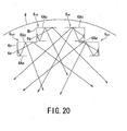
- the LED module 6a is arranged in an eccentric manner towards the low reflection mirror 6Ae that faces the reflection mirror 6Ac that has the highest height.
- the reason for this is that, by arranging the LED module 6a that is the light source away from the highest reflection mirror 6Ac that can irradiate reflected light farther than the low reflection mirror 6Ae, it is possible to reduce the reflection angle at the reflection mirror 6Ac and to extend the irradiation distance of reflected light from the reflection mirror 6Ac.
- Fig. 20 is a schematic diagram that illustrates the reflection action of the reflection mirror 6Ac with a high height and the reflection mirror 6Ae with a lower height than the reflection mirror 6Ac that faces the reflection mirror 6Ac in the LED optical unit 6A.
- the reflected light is reflected again by the reflection mirror 6Ac that has a high height that faces the reflection mirror 6Ae and is irradiated to the proximity of the relatively inner side (in) in the width direction (the left-to-right direction in Fig. 20 ) of the top cover 4.
- the luminous flux decreases somewhat due to reflection loss because the light emitted from the LED module 6a is reflected twice, namely, at the low reflection mirror 6Ae and at the high reflection mirror 6Ac.
- the light intensity is sufficient for the proximate irradiation.
- the plurality of LED optical units 6A are symmetrically arranged on the left and right in the drawings with respect to the central axis O in the width direction that extends in the longitudinal direction (front-to-rear direction in Fig. 20 ) of the center in the width direction within the top cover 4. Hence, the uniformity ratio of illuminance on a horizontal plane directly under the top cover 4 in Fig. 20 can be improved.
- the plurality of LED optical units 6A and 6A that are arranged on one side, respectively, with respect to the central axis O in the width direction of the top cover 4 are arranged on two upper and lower levels in the drawings, and there is a difference in level between adjacent LED optical units 6A and 6A in the width direction of the top cover 4 (see Fig. 17 ). Hence, it is possible to prevent or lessen the occurrence of a shadow caused by light irradiated from the LED optical units 6A and 6A being blocked by the other LED optical unit 6A.
- the reflection mirrors 6Ad and 6Af of the LED optical unit 6A can likewise perform distant irradiation and proximate irradiation by means of reflection mirrors of different heights.
- the front face of the ceramic substrate 6b is elastically supported by the upper and lower pair of plate springs 8a and 8b that are an example of a presser that are screwed into the unit support plate 9. More specifically, the ceramic substrate 6b is elastically sandwiched in the thickness direction by the upper and lower pair of plate springs 8a and 8b and the unit support plate 9.
- the upper ends and lower ends of the plate springs 8a and 8b are fixed by screwing to the upper and lower ends of the unit support plate 9, respectively.
- a plurality of the LED optical units 6 that are constructed in this manner are detachably attached by bolts or screws Sa or the like to a unit mounting plate 10 that is formed in a band-plate shape.
- a unit mounting plate 10 that is formed in a band-plate shape.
- two of the second inner side LED optical units 6Ain (upper level) are arranged side by side and, for example, three of the outer side LED optical units 6Aout (lower level) are arranged side by side.
- the unit mounting plates 10 are fixed at required places to the inner surface of the aforementioned top cover 4 by being firmly adhered by screwing to a mounting boss that is integrally provided in a protruding condition on the inner surface of the top cover 4. More specifically, all of the second LED optical units 6A, 6A, ... are detachably fixed to the inner surface of the top cover 4. At the time of fixing, at least one part of the unit support plate 9 of the second LED optical units 6A, 6A, ...
- a heat dissipating body such as a metal plate with excellent heat dissipation properties or a heat pipe to thereby enhance the heat dissipation properties of the lighting apparatus 1A.
- a plurality of power source systems for example, two systems, are provided as the power source systems of the second LED optical units 6A, 6A, ... that are constructed in the above manner. More specifically, a plurality of power source systems may be respectively provided for the left and right sides of the lighting of the second LED optical units 6A, 6A, ... when taking the central axis O as an axis of symmetry. Accordingly, even if there is a malfunction in one of the systems, as long as there is not a malfunction in the other system it is possible to light the other second LED optical units 6A, 6A, ... on the left and right, and thus a situation in which all of the second LED optical units 6A, 6A, ... do not emit light can be prevented.
- the second LED optical units 6A include a forward irradiation LED optical unit 6F shown in Fig. 21 and a backward irradiation LED optical unit 6B shown in Fig. 22 .
- the forward irradiation LED optical unit 6F includes a wedge-shaped forward spacer 11 that causes a light emitting surface 6aa of the LED module 6a and a front face 6bc of the ceramic substrate 6b to incline in a forward direction F, that is, towards the opposite side of the pole 2 that is the support column.
- the spacer 11 is made of a material that has excellent heat dissipation properties such as die-cast aluminum.
- the forward irradiation LED optical units 6F are arranged on the two upper and lower (inner and outer sides) levels at a rear portion of the case main body 3.
- the backward irradiation LED optical unit 6B includes a wedge-shaped backward spacer 12 that is made of die-cast aluminum metal or the like that causes the light emitting surface 6aa of the LED module 6a and the front face 6bc of the ceramic substrate 6b to incline in a backward direction B.
- the backward irradiation LED optical units 6B are arranged in left and right pairs at a front portion inside the case main body 3.
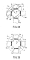
- Fig. 24 illustrates light distribution characteristics when a single lighting apparatus 1A according to the second embodiment constructed in this manner is, or example, erected on an outer side at a corner of a cross-shaped intersection of a road.
- the lighting apparatus 1A is erected so that the head thereof faces a center point OA of the road intersection.
- the light distribution of the lighting apparatus 1A includes left and right backward light distributions 13a and 13b when light is irradiated in both the left and right directions in a backward direction B, respectively, by two backward irradiation LED optical units 6B and 6B on the left and right that are arranged at the front portion of the case main body 3, and a forward light distribution 14 when light is irradiated in a forward direction F by a total of eight forward irradiation LED optical units 6F, 6F, ... that comprise four left and right pairs that are arranged at the rear portion of the case main body 3.
- the light distribution of the lighting apparatus 1A is an approximately elliptic-shaped combined light distribution 15 which combines the approximately triangular forward light distribution 14 and the backward light distributions 13a and 13b.
- the combined light distribution 15 can illuminate the roads at the intersection at which the lighting apparatus 1A is erected in an approximately elliptical shape that is centered on one corner, and the intersection center OA and an area including two pedestrian crossings 16a and 16b at which the lighting apparatus 1A is installed can be illuminated.
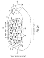
- Fig. 25 shows a combined light distribution 17 when four of the lighting apparatuses 1A, 1A, ... are erected at the corners of the aforementioned intersection.
- the combined light distribution 17 an area within a radius including a region somewhat to the back of the four lighting apparatuses 1A, 1A, ... from the intersection center OA can be illuminated, and all of four pedestrian crossings 16a to 16d of the intersection can be illuminated.
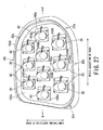
- Fig. 26 is a bottom view of an lighting apparatus 1C according to a third embodiment of the present invention.
- the lighting apparatus 1C is an lighting apparatus that can be used, for example, as a road light on a road such as a highway or an ordinary road or the like.
- a feature of the lighting apparatus 1C is that, relative to the lighting apparatus 1 according to the first embodiment described above, a third optical unit 6C is used in place of the LED optical unit 6.
- an LED (light emitting diode) module 6aC is integrally mounted on a ceramic substrate 6bC that is an example of a support substrate thereof.
- the LED module 6aC includes a COB (chip on board) type pseudo-white (blue-yellow system) LED bare chip 6ab as a light emitting element. More specifically, the LED module 6aC includes a required number (for example, 196) of LED bare chips 6ab that emit blue light.
- the LED bare chips 6ab are directly mounted on a printed circuit board on which a circuit is formed, and arranged in a plurality of rows (14 rows, for example) and a plurality of columns (14 columns, for example). Subsequently, a resin containing phosphors that emit yellow light is applied onto the LED bare chips 6ab, the resulting structure is sealed by a silicone resin, and then adhered, for example, by a silicone resin on a substrate.
- the LED module 6aC is adhered by a silicone resin to an approximately center section of a front face (upper face in Fig. 30 ) of the white ceramic substrate 6bC that is formed in the shape of a rectangular flat plate. Consequently, a light emitting surface 6aaC of the LED module 6aC is formed in a state in which the light emitting surface 6aaC protrudes somewhat more upward than a front face 6bcC (upper face in Fig. 30 ) of the ceramic substrate 6bC.
- the third optical unit 6C and an irregularly shaped lens 20 that covers approximately the entire front face (upper face) of the LED module 6aC are formed in an integrated manner in advance by adhering a bottom face in Fig. 30 of the irregularly shaped lens 20 onto the front face 6bcC of the third optical unit 6C by means of a silicone resin to thereby constitute the third optical unit 6C.
- a concave portion 20a that accommodates approximately the entire LED module 6aC is formed in an opposing face (bottom face) that opposes the LED module 6aC.
- An outer peripheral edge portion (bottom face) of the concave portion 20a is adhered by means of a silicone resin on the ceramic substrate 6bC.
- a spherical lens portion 20c is provided in an integrally protruding manner on an approximately center section of a translucent lens base 20b in which a planar shape is a rectangular flat plate shape.
- a planar shape is formed in an approximately oblong shape and, for example, a pair of spherical parts 20ca and 20cb that have a hemispherical shape are integrally formed at both end portions in the long diameter direction thereof.
- a lens concave portion 20cc is integrally formed that is lower by a required height than the apexes of the spherical parts 20ca and 20cb.
- emitted light from the LED module 6aC is mainly emitted outward from respective ends in the longitudinal direction of the spherical lens portion 20c, and is also emitted in the transverse direction.
- reference character 1 denotes a lead wire of the third optical unit 6C.
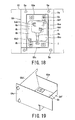
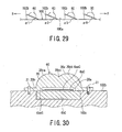
- a plurality of the third optical units 6C constructed in this manner are fixed to a unit mounting plate 10C that, for example, is formed in the shape of a rectangular flat plate that is made of aluminum. More specifically, as shown in Fig. 29 , a plurality of mounting step portions 10Cb, 10Cb, ... to which a plurality of the third optical units 6C are mounted, respectively, are provided in a protruding condition on a front surface 10Ca of the unit mounting plate 10C.
- the mounting step portions 10Cb, 10Cb, ... are respectively formed at angles of inclination ⁇ 1, ⁇ 2, ⁇ 3, ⁇ 4 that incline downward from a rear portion R side toward a front portion F side of the unit mounting plate 10C.
- the angles of inclination ⁇ 1 to ⁇ 4 are all equal at, for example, the mounting step portions 10Cb, 10Cb, ...
- a concave accommodating portion 10Cc configured to accommodate therein the ceramic substrate 6bC of the respective third optical units 6C is formed in each mounting step portion 10Cb.
- Each concave accommodating portion 10Cc is formed so that the depth dimension thereof is approximately equal to the plate thickness of the ceramic substrate 6bC.
- the aforementioned plurality of mounting step portions 10Cb, 10Cb, ... are arranged in, for example, approximately three rows and three columns (however, there are four columns in a middle row) on the unit mounting plate front surface 10Ca so as to be disposed in a staggered shape, and not in the shape of a straight line, along a width direction (transverse direction) of the case main body 3 and the unit mounting plate 10C, that is, along a longitudinal direction of a road.
- the plurality of mounting step portions 10Cb, 10Cb, ... are mounted to the apparatus main body A in such a way that the portions 10Cb, 10Cb, ... are disposed so as to be staggered relative to and to deviate from adjacent portions 10Cb, 10Cb, ... in the width direction of the apparatus main body A or in the longitudinal direction of the apparatus main body A.
- Screw insertion holes are respectively formed at, for example, a plurality of corner portions of the lens base 20b of each optical unit 6C.
- the respective optical units 6C are detachably mounted on the respective mounting step portions 10Cb of the unit mounting plate 10C by being fastened thereto by a plurality of fastening screws 21 and 21 that are inserted through the screw insertion holes.
- the third optical units 6C, 6C, ... are arranged in a staggered shape along the width direction (transverse direction) of the case main body 3 and the unit mounting plate 10C, that is, along a longitudinal direction of a road. Consequently, the occurrence of a situation in which light irradiated in the width direction (transverse direction) of the case main body 3 from the optical units 6C, 6C, ..., that is, in the longitudinal direction of a road, is blocked by other optical units 6C, 6C, ... adjacent to the relevant optical unit 6C in the longitudinal direction of the road can be reduced, and an improvement in the irradiation efficiency can be expected.
- a flange 10Cd of a required width that rises by a required height is integrally provided in a protruding condition at an outer peripheral edge portion of the front surface 10Ca of the unit mounting plate 10C.
- Insertion holes for mounting 22a, 22a, ... are formed with a required space therebetween in a circumferential direction in the flange 10Cd.
- an upper end portion in the drawing of a plurality of columnar mounting bosses 22, 22, ... formed at corner portions of a lower end in the drawing of the case main body 3 that forms one end portion of the apparatus main body A are inserted through the insertion holes for mounting 22a, 22a,....
- the unit mounting plate 10C can be fixed to the case main body 3 by fastening a set screw 23 in a screw hole of each mounting boss 22, respectively.
- a side face of the unit mounting plate 10C contacts against an inside surface of the case main body 3, and heat generated by the third optical units 6C, 6C, ... is transferred to the case main body 3 through the unit mounting plate 10C and is released to the outside air from the outer surface of the case main body 3.
- the translucent plate 5 comprising tempered glass is fitted in the opening 3k on the irradiation side of the case main body 3.
- the case main body 3 is configured in the same manner as the case main body 3 according to the first and second embodiments described above, and the apparatus main body A is constituted by detachably mounting the top cover 4 that is made of a die-cast aluminum material on an upper end 3d of an opening of the case main body 3 by screwing or the like.
- the outer shape and configuration of the top cover 4 are formed in the same manner as the top cover 4 according to the first and second embodiments described above.
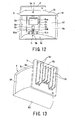
- a power supply apparatus 24 that includes a lighting circuit (not shown in the drawing) that controls lighting and shutting off and the like of the third optical units 6C, 6C, ... is mounted to, for example, an inner face of the concave portion 4e at the upper end in the drawing of the top cover 4.
- the output sides of an unshown power source line and control line that are connected to the power supply apparatus 24 are connected to the lead wire 1 as shown in Fig. 28 of each optical unit 6C, 6C, ....
- the input sides of the aforementioned power source line and control line extend to the electricity chamber 3a at the rear end portion that is on the rearward R side of the case main body 3, and are respectively connected to a power source terminal and a control terminal that are omitted from the drawings.
- the power supply apparatus 24 is constituted by mounting a plurality of electrical components 24b, 24b that comprise a lighting circuit or a power supply circuit or the like on at least one face of a substrate 24a comprising a rectangular flat plate made of aluminum that has heat dissipation properties and rigidity.
- a plurality of insertion holes are formed in the substrate 24a.
- Lower end portions in Fig. 31 of a plurality of columnar mounting bosses 25, 25, ... that are provided in a protruding condition on an inner face of the top cover 4 are inserted through the aforementioned plurality of insertion holes, respectively.
- the substrate 24a is fixed inside the top cover 4 by inserting the lower end portions in the drawing of the mounting bosses 25, 25, ... into the insertion holes and screwing set screws 26, 26, ... into screw holes in insertion tip portions thereof.
- the LED modules 6aC, 6aC, ... of the third optical units 6C, 6C, ... are supplied with electricity by the power source line, the LED modules 6aC, 6aC, ..., for example, emit white light.
- the mounting step portions 10Cb, 10Cb, ... of the unit mounting plate 10C to which the third optical units 6C, 6C, ... are fixed are formed at angles of inclination ⁇ 1 to ⁇ 2 that incline downward towards the front F of the case main body 3, the white light is mainly irradiated towards the front F, that is, frontward in the road width direction.
- angles of inclination ⁇ 1 to ⁇ 4 of the mounting step portions 10Cb, 10Cb, ... gradually decrease towards the front F from the back B side, it is possible to reduce the occurrence of a situation in which light is blocked by the third optical units 6C, 6C, ... that are adjacent to each other in the front-to-rear direction.
- the third optical units 6C, 6C, ... also irradiate white light emitted by the LED modules 6aC, 6aC, ... in the longitudinal direction of the irregularly shaped lens 20, more specifically, the width (transverse) direction of the case main body 3, that is, the longitudinal direction of a road.
- the arrangement of the third optical units 6C, 6C, ... in the longitudinal direction of the road is staggered, it is possible to reduce the occurrence of a situation in which light is blocked by the third optical units 6C, 6C, ... that are adjacent to each other in the longitudinal direction of the road.
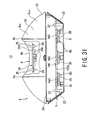
- the power supply apparatus 24 that generates heat is arranged inside the top cover 4 on the upper side in Fig. 31 of the apparatus main body A.
- the third optical units 6C, 6C, ... and the power supply apparatus 24 are arranged so that there is a clearance therebetween in the vertical direction, an increase in the temperature of the case main body 3 can be reduced in comparison to a configuration in which the power supply apparatus 24 is arranged inside the case main body 3 together with the third optical units 6C, 6C, ....
- the heat dissipation properties thereof can be improved. Further, the heat dissipation properties can be enhanced by facilitating natural convection inside the light source chamber 3c within the top cover 4.
- the number of the third optical units 6C, 6C, ... is not limited thereto, and the number of third optical units 6C, 6C, ... may be more than ten or less than ten.
- each third optical unit 6C is unitized by integrally assembling in advance the LED module 6aC, the ceramic substrate 6bC and the irregularly shaped lens 20, and is detachably provided on the unit mounting plate 10C that is arranged inside the case main body 3, each optical unit 6C can be individually replaced. Therefore, even if a malfunction occurs in some of the plurality of third optical units 6C, 6C, ..., the costs can be reduced in comparison to replacing the entire lighting apparatus 1C.
- the LED module 6aC is supported by the ceramic substrate 6bC that has excellent heat transfer properties, the heat dissipation properties with respect to heat generation of the LED module 6aC can be enhanced. Further, since the ceramic substrate 6bC that is generally fragile is adhered to the irregularly shaped lens 20 by means of a silicone resin without being screwed, damage of the ceramic substrate 6bC can be reduced.
Landscapes
- Engineering & Computer Science (AREA)
- General Engineering & Computer Science (AREA)
- Physics & Mathematics (AREA)
- Geometry (AREA)
- Non-Portable Lighting Devices Or Systems Thereof (AREA)
- Arrangement Of Elements, Cooling, Sealing, Or The Like Of Lighting Devices (AREA)
Abstract
Description
- Embodiments described herein relate generally to a lighting apparatus.
- A lighting apparatus lighting apparatus is sometimes constructed so that the light irradiation directions of respective LED modules can be adjusted. One way of adjusting the light irradiation directions is to adjust a mounting angle of the relevant LED module that is arranged on the apparatus main body. When using this way, the lighting apparatus does not include a reflecting mirror.
- However, when lighting apparatus does not include a reflecting mirror, the distribution of light of the LED modules is hard to control. Hence, there occurs the problem that a large quantity of light leaks to outside of the region to be illuminated, and therefore the illumination efficiency is not high. In particular, since light irradiated in the width direction of a road that is the illumination object cannot be controlled by a reflecting mirror, a large quantity of light leaks to the width direction of the road and there is a significant risk of the leaking light adversely affecting neighboring residences.
- Further, since a plurality of LED modules are fixed to the mount of the lighting apparatus, for example, if a malfunction such as a non-lighting occurs in one part of an LED module, it is not possible to replace only the LED module in which the malfunction has occurred, and the entire lighting apparatus must be replaced. Hence, there is also the problem that the maintenance costs are high.
-
-
Fig. 1 is a bottom view of an lighting apparatus according to the first embodiment of the present invention; -
Fig. 2 is an external perspective view when a state in which the lighting apparatus shown inFig. 1 is arranged on a support column is viewed from underneath; -
Fig. 3 is an external perspective view when the lighting apparatus shown inFig. 1 andFig. 2 is viewed from overhead; -
Fig. 4 is a front view of the lighting apparatus shown inFigs. 1 to 3 ; -
Fig. 5 is a plan view of the lighting apparatus shown inFigs. 1 to 3 ; -
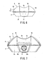
Fig. 6 is a left side view of the lighting apparatus shown inFigs. 1 to 3 ; -
Fig. 7 is a right side view of the lighting apparatus shown inFigs. 1 to 3 ; -
Fig. 8 is a schematic sectional view along a line VIII-VIII inFig. 1 ; -
Fig. 9 is a plan view when two of the LED optical units shown inFig. 1 andFig. 2 are arranged side by side on a unit support plate; -
Fig. 10 is a front view when an LED optical unit shown inFig. 8 is viewed from the front of an irradiation opening thereof; -
Fig. 11A is a schematic end view of a cross section along a line XI-XI shown inFig. 10 ; -
Fig. 11B is a schematic sectional view that shows a modification example ofFig. 11A ; -
Fig. 12 is a perspective view of an LED optical unit shown inFig. 1 and the like when viewed from the front; -
Fig. 13 is a perspective view of the LED optical unit shown inFig. 1 and the like when viewed from the rear; -
Fig. 14 is an elevated perspective view of an lighting apparatus arranged on a curved pole; -
Fig. 15 is a bottom view of an lighting apparatus according to a second embodiment of the present invention; -
Fig. 16 is a plan view of the inner surface of a top cover of the lighting apparatus shown inFig. 15 ; -
Fig. 17 is a cross-sectional side view of the lighting apparatus shown inFig. 15 ; -
Fig. 18 is a plan view of an LED optical unit shown inFig. 15 to Fig. 17 ; -
Fig. 19 is a perspective view of a reflector shown inFig. 15 to Fig. 17 ; -
Fig. 20 is a schematic diagram that illustrates a reflection action of the optical unit shown inFig. 15 to Fig. 17 ; -
Fig. 21 is a side view of a forward irradiation LED optical unit shown inFig. 15 to Fig. 17 ; -
Fig. 22 is a side view of a backward irradiation LED optical unit shown inFig. 15 to Fig. 17 ; -
Fig. 23 is a sectional view along a line XXIII-XXIII inFig. 17 ; -
Fig. 24 is a view that illustrates light distribution characteristics when a single lighting apparatus shown inFig. 15 to Fig. 22 is erected on the outer side of one corner of a cross-shaped intersection of a road; and -
Fig. 25 is a view that illustrates combined light distribution characteristics when four of the lighting apparatuses shown inFig. 15 to Fig. 22 are erected at a cross-shaped intersection of a road. -
Fig. 26 is a bottom view of an lighting apparatus according to a third embodiment of the present invention; -
Fig. 27 is a perspective view that shows a state in which a plurality of the optical units are arranged on a unit mounting plate; -
Fig. 28 is an enlarged plan view of the optical unit shown inFig. 26 andFig. 27 ; -
Fig. 29 is a side view of a plurality of the optical units that are arranged at an intermediate portion in a transverse direction of the unit mounting plate shown inFig. 27 ; -
Fig. 30 is a sectional view along a line XXX-XXX inFig. 27 ; and -
Fig. 31 is a view that shows a cross section of one portion (lower portion inFig. 31 ) of the lighting apparatus when viewed from a front end that is the left end inFig. 26 , that shows a notch that is formed in a part of another portion (upper portion inFig. 31 ) of the lighting apparatus. - A lighting apparatus according to an embodiment will be described with reference to the accompanying drawings. The lighting apparatus according to an embodiment includes an optical unit and a body. The Optical unit includes a light emitting module that has a light emitting element, a reflector that controls distribution of light from the light emitting module, and a unit supporting member that supports the light emitting module and the reflector. A plurality of optical units are mounted to the apparatus body such that each optical unit is detachable. And the body includes an irradiating portion that has an opening through which the optical units irradiate light.
-
Fig. 2 is an external perspective view when a state in which an lighting apparatus according to one embodiment of the present invention is arranged on a pole (support column) is viewed from underneath.Fig. 3 is an external perspective view when the lighting apparatus according to one embodiment of the present invention is viewed from overhead.Fig. 4 is a front view of the lighting apparatus according to one embodiment of the present invention.Fig. 5 is a plan view of the lighting apparatus according to one embodiment of the present invention. - As shown in the aforementioned drawings, an
lighting apparatus 1 according to the embodiment can be used, for example, as a road light or the like on a road such as a highway or an ordinary road. Hence, a case is described hereunder in which the lighting apparatus is applied to a road light. As shown inFig. 2 , thelighting apparatus 1 is arranged at, for example, a height of approximately 10 meters above ground by apole 2 comprising a hollow circular column or a hollow angular column or the like as a support column. Thepole 2, for example, is firmly erected above the ground at the outer side of an edge in the width direction of a road such as a highway, and a plurality of thepoles 2 are erected at a required pitch in the longitudinal direction of the road. As shown inFig. 3 to Fig. 5 , thelighting apparatus 1 has an apparatus main body A. The apparatus main body A is constituted by hermetically closing anupper end 3d of an opening of a casemain body 3 by fixing atop cover 4 that is one example of a cover to an open end of the upper surface in the drawing of the casemain body 3 by screwing thetop cover 4 to the open end or the like. - As shown in
Fig. 3 , a planar shape of thetop cover 4 is formed in an approximately oblong shape by, for example, a die-cast aluminum material. Thetop cover 4 is formed so that a length W thereof along a width direction (the left-to-right direction inFig. 4 and Fig. 5 ) of a road (not shown in the drawings) that is one example of an illumination object is longer than alength 1 along a longitudinal direction (vertical direction inFig. 4 and Fig. 5 ) of the road. - As shown in
Fig. 3 to Fig. 7 , the upper surface of thetop cover 4 in the drawings has acurved surface 4b which protrudes outward in a manner in which an approximately center section thereof is an apex 4a. In thecurved surface 4b, a pair of projectingportions top cover 4. - The projecting
portions top cover 4. A band-shapedconcave portion 4e that is recessed in the shape of a concave arc on the inner side is integrally coupled between the projectingportions - The concave arc-shaped
concave portion 4e is integrally coupled to a front end portion (left end portion inFig. 4 and Fig. 5 ) 4f and a rear end portion (right end portion inFig. 4 and Fig. 5 ) 4g by downwardinclined planes center section 4a of thetop cover 4 towards thefront end portion 4f and therear end portion 4g, respectively. More specifically, the outer surface of thetop cover 4 is formed in a streamline shape that reduces air resistance when external air flows in the longitudinal direction and the width direction as shown by the arrows inFig. 3 . - As shown in
Fig. 4 , the rear end of therear end portion 4g of thetop cover 4 is rotatably attached to an upper end portion of the rear end (right end inFig. 4 ) of the casemain body 3. Thus, thetop cover 4 is formed as an opening/closing cover that can open and close in the direction of the white arrow inFig. 4 . - An
electricity chamber 3a is formed inside the rear end portion (right end portion inFig. 4 ) of the casemain body 3 below the opening/closing cover 4g inFig. 4 . Theelectricity chamber 3a is partitioned from alight source chamber 3c, described later, by apartitioning wall 3b indicated by a dashed line inFig. 4 . A power source terminal (omitted from the drawings), a power source line that is connected to the power source terminal, and one end of a lighting control line are housed in theelectricity chamber 3a in a watertight manner. - As shown in
Fig. 7 , a pole coupling portion 3ma that has a lateral hole forpole insertion 3m into which a distal end portion of acurved pole 2a shown inFig. 14 is inserted and fixed is formed in the rear end wall of the casemain body 3 that is the rear end wall of theelectricity chamber 3a. - As shown in
Fig. 2 the casemain body 3 that has a polygonal cylindrical shape in which an opening is formed in the upper and lower ends in the drawing is detachably coupled by screwing to a lower end of an opening in the drawing of thetop cover 4. In the casemain body 3, a planar shape of anupper end portion 3d that is coupled with thetop cover 4 is formed in a polygonal, flat cylindrical shape that is formed in an approximately oblong form that is the same form and same size as the oblong form of the planar shape of thetop cover 4. Further, aside surface 3e is formed in an inclined plane that gradually decreases towards thelower end 3f in the drawing. A large opening portion (omitted from the drawings) that passes through almost the entire surface of the upper end in the drawings of thelight source chamber 3c is formed in theupper end portion 3d of the casemain body 3. -
Fig. 1 is a bottom view of thelower end 3f of the casemain body 3. As shown inFig. 1 , in the casemain body 3, apole coupling portion 3i that has a vertical hole forpole insertion 3h into which, for example, a distal end portion of thepole 2 that has a straight bar shape that is shown inFig. 2 is inserted and fixed is formed in thelower end portion 3f of a rear end portion (right end inFig. 1 ) 3g on theelectricity chamber 3a side thereof. Apolygonal opening 3k having a shape of a horizontally-long rectangle in which each corner portion has been chamfered is formed on a front end portion (left end inFig. 1 ) 3j side of the casemain body 3. Atranslucent plate 5 comprising tempered glass that is one example of a translucent body is arranged in theopening 3k to seal thelight source chamber 3c in a watertight and airtight manner. A plurality of LEDoptical units Fig. 1 , four horizontal rows, and housed inside thelight source chamber 3c. - A required number, for example, five, of the LED
optical units Fig. 1 ), respectively, taking a central axis O that passes through the center of the four rows in the front-to-rear direction (the left-to-right direction inFig. 1 ) of the casemain body 3 as an axis of symmetry. - The LED
optical units optical units optical units optical units irradiation openings 6g thereof so as to cross with respect to each other towards the opposite sides in the left-to-right direction, the respective irradiation lights from the LEDoptical units optical units - As shown in
Fig. 8 , when thetop cover 4 and the casemain body 3 are joined together, the inner space thereof is formed into a lightsource housing portion 7 that houses a plurality of the LEDoptical units source housing portion 7, each LED optical unit 6in as a first one of the plurality of theoptical units 6 of the array on the inner side is disposed above, that is, at a higher position than (upper level), each LED optical unit 6out as a second one of the plurality of theoptical units 6 of the array on the outer side. The inner side and outer side LED optical units 6in and 6out that are arranged on the left and right inFig. 8 are aligned in a truncated chevron shape that expands like a folding fan in the downward direction in the drawings, and are aligned in an intersecting truncated chevron shape. In order to irradiate light in the proximity of thelighting apparatus 1, each LED optical unit 6in on the inner side is fixed in an inclined state so that a light axis La of the irradiation light thereof is at a required angle θa (for example, 50°) with respect to the surface of thetranslucent plate 5. Further, in order to irradiate light to an area farther away than the proximity of thelighting apparatus 1, each LED optical unit 6out on the outer side is fixed in an inclined state so that a light axis Lb of the irradiation light thereof is at a required angle θb (for example, 60°) with respect to the surface of thetranslucent plate 5. - As shown in
Fig. 1 andFigs. 8 to 13 , each LEDoptical unit 6 has an LED (light emitting diode)module 6a, aceramic substrate 6b that is an example of a support substrate thereof, an upper and lower pair offlat mirrors Fig. 10 as a first reflective surface, a left and right pair of side curvedmirrors Fig. 10 as a second reflective surface, and a reflectingtube 6i that is constructed as a trumpet-shaped angular cylindrical body in which the fourmirrors 6c to 6f are unified or joined in an integrated manner. The reflectingtube 6i has arectangular irradiation opening 6g that expands in a trumpet shape, and abottom portion 6j whose diameter contracts in a trumpet shape on the opposite side in the axial direction thereof. - As shown in
Fig. 10 , theLED module 6a, for example, includes a COB (chip on board) type pseudo-white (blue-yellow system) LED bare chip 6ab as a light emitting element. More specifically, theLED module 6a includes a required number (for example, 196) of LED bare chips 6ab that emit blue light. The LED bare chips 6ab are directly mounted on a printed circuit board on which a circuit is formed, and arranged in a plurality of rows (14 rows, for example) and a plurality of columns (14 columns, for example). Subsequently, a resin containing phosphors that emit yellow light is applied onto the LED bare chips 6ab, the resulting structure is sealed by a silicone resin. TheLED module 6a constructed in this manner is adhered by, for example, a silicone resin or the like on an approximately center section of a front face 6bc of theceramic substrate 6b. - More specifically, as shown in
Fig. 11A , a back side end portion of theceramic substrate 6b is fitted inside afitting opening portion 9k of aunit support plate 9 as a unit supporting member. TheLED module 6a is adhered to theceramic substrate 6b so that, in this fitted state, a light emitting surface 6aa of theLED module 6a is caused to protrude somewhat more upward in the drawing ofFig. 11A , that is, more frontward, than an inner bottom face 6jc of abottom portion 6j on the contracted diameter side of the reflectingtube 6i so as to be exposed to outside. Consequently, the light emitting surface 6aa of theLED module 6a is arranged so as to be at a position that protrudes somewhat more forward than the inner bottom face 6jc of thebottom portion 6j on the contracted diameter side of the reflectingtube 6i in this adhered state.Fig. 11B is a longitudinal sectional view that illustrates a modification example of positioning of theceramic substrate 6b shown inFig. 11A . According to this modification example, by making a depth of thefitting opening portion 9k of theunit support plate 9 with which theceramic substrate 6b is engaged deeper than thefitting opening portion 9k shown inFig. 11A , the front face 6bc of the upper surface in the figure of theceramic substrate 6b may be configured to be approximately matched and be flush with afront face 9a of theunit support plate 9. - With respect to the trumpet-shaped reflecting
tube 6i shown inFig. 12 , the left and right pair of side curvedmirrors tube 6i mainly controls the light distribution of light irradiated from theLED module 6a in the width direction of the road. More specifically, each of the LEDoptical units Fig. 1 . In this connection, portions represented by a plurality of parallel vertical lines of each of the side curvedmirrors Fig. 1 indicate the respective curved inner surfaces (that is, the reflective surfaces) of each of the side curvedmirrors - The upper and lower pair of
flat mirrors mirrors Fig. 12 and Fig. 13 to thereby form the reflectingtube 6i as a bottomed, trumpet-shaped angular cylindrical body that gradually expands towards anillumination opening 6g. As shown inFig. 10 andFig. 12 , the trumpet-shaped reflectingtube 6i forms afitting opening portion 6k that interfits with the aforementionedceramic substrate 6b on a center section of abottom portion 6j on the contracted diameter side of the reflectingtube 6i. Theceramic substrate 6b is accommodated inside thefitting opening portion 6k. When theceramic substrate 6b is accommodated therein, as shown inFigs. 11A and 11B , a front face 6bc of theceramic substrate 6b is approximately flush with an inner surface 6jc of thebottom portion 6j of the reflectingtube 6i. A reflective surface such as a mirror surface is formed on the inner surface of the upper and lower pair offlat mirrors flat mirrors flat mirrors irradiation opening 6g so as to magnify the irradiated light. Further, as shown inFig. 9 , heat dissipation holes h and h are formed in the vicinity of theLED module 6a in the upper and lower pair offlat mirrors - The flat and side mirrors 6c to 6f are configured so that primary reflected light converges at a height of approximately 7 meters above ground when the apparatus main body A is arranged at a height of approximately 10 meters above ground by means of the
pole 2. - The back surface of the
ceramic substrate 6b is fitted inside thefitting opening portion 9k formed on thefront face 9a of theunit support plate 9 that is formed in the shape of a rectangular flat plate that is made of a metal such as aluminum that is shown inFig. 9 ,Figs. 11A and 11B ,Fig. 12, and Fig. 13 . In this fitted state, the front face of theceramic substrate 6b is elastically supported by free ends of an upper and lower pair of plate springs 8a and 8b that are an example of a presser. An end on a side opposite to the free end of the plate springs 8a and 8b is fixed by screwing to theunit support plate 9. More specifically, theceramic substrate 6b is elastically sandwiched in the thickness direction by the upper and lower pair of plate springs 8a and 8b and theunit support plate 9. - The upper end and lower end of the plate springs 8a and 8b screwed into the upper and lower ends of the
bottom portion 6j of the reflectingtube 6i, respectively, to thereby fix the plate springs 8a and 8b thereto. Each inner end portion of the plate springs 8a and 8b protrudes over the front face of theceramic substrate 6b. Slits 8aa and 8ba that open at an inner end and extend in the vertical direction inFig. 10 are formed in the protruding end portions, respectively. Small engagement protrusions 6ba and 6bb formed in a vertically long rectangular shape are provided in a protruding condition at the upper end and lower end of the front face of theceramic substrate 6b, respectively. By inserting the small engagement protrusions 6ba and 6bb into the slits 8aa and 8ba, theceramic substrate 6b is supported with a certain degree of play. InFig. 10 ,reference symbol 6h denotes a power supply connector that is electrically and detachably connected to theLED module 6a. Theconnector 6h is electrically connected to a power source terminal inside theelectricity chamber 3a by alead wire 1. - As shown in
Fig. 9 andFig. 13 , a plurality ofheat dissipation fins back face 9b of theunit support plate 9 in the LEDoptical unit 6. The outward protruding length of theheat dissipation fins Fig. 9 andFig. 13 , the outward protruding length of several of theheat dissipation fins heat dissipation fins - As shown in
Fig. 9 , a plurality of the LEDoptical units 6 that are constructed in this manner are detachably attached by bolts or screws S or the like to aunit mounting plate 10. Theunit mounting plate 10 is formed in a band-plate shape. - More specifically, a
rectangular insertion hole 10a through which the plurality ofheat dissipation fins unit mounting plate 10. Thesupport plate 9 of the LEDoptical unit 6 is detachably fixed by a screw S to theunit mounting plate 10 in a state in which the plurality ofheat dissipation fins insertion hole 10a. On theunit mounting plates 10, for example, two of the inner side LED optical units 6in are arranged side by side and, for example, three of the outer side LED optical units 6out are arranged side by side. Theunit mounting plates 10 are fixed at required places on the inner surface of the aforementionedtop cover 4. More specifically, all of the LEDoptical units top cover 4. At the time of fixing, at least one part of theunit support plate 9 of the LEDoptical units top cover 4 or is brought in contact with the inner surface of thetop cover 4 through a heat dissipating body such as a metal plate with excellent heat dissipation properties or a heat pipe to thereby enhance the heat dissipation properties of thelighting apparatus 1. - A plurality of power source systems, for example, two power source systems, are provided at a part of the LED
optical units optical units optical units - Consequently, even if one of the power source systems is cut off due to some cause, the LED
optical units optical units - The plurality of power source systems may also be connected to the LED
optical units optical units - For example, a configuration may be adopted in which two power source systems are provided, and one of the power source systems is connected to each of the four inner side LED optical units 6in, 6in, ..., and the other power source system is connected to each of the six inner side LED optical units 6out, 6out, .... According to this configuration, even if one of the power source systems is cut off, either one of the inner side and outer side LED optical units 6in, 6out, ... can be caused to irradiate light and, furthermore, the bilateral symmetry can be maintained when irradiating light.
- The power source lines of the plurality of systems are connected to a secondary side of a power source terminal block inside the
electricity chamber 3a of the casemain body 3. An unshown primary-side power source line is electrically connected to the primary side of the power source terminal bock. The primary side power source line is passed through the inside of thehollow pole 2 and electrically connected to an unshown power supply apparatus. The power supply apparatus includes a control apparatus (not shown in the drawings) that controls a lighting circuit of the LEDoptical units pole 2 at a height above ground level that allows a worker to easily perform operations relating to the power supply apparatus above ground level. - Next, the action of the
lighting apparatus 1 will be described. - When the
LED modules 6a of the LEDoptical units LED module 6a, for example, emits white light. The white light is reflected by the upper and lower pair offlat mirrors side mirrors translucent plate 5 side from theirradiation opening 6g. The white light is transmitted through thetranslucent plate 5 and is irradiated onto the road that is the illumination object. - Since the upper and lower pair of
flat mirrors flat mirrors mirrors mirrors mirrors - More specifically, since the
lighting apparatus 1 can control an illuminating angle in the width direction of the road for each LEDoptical unit 6, leaking light can be reduced by appropriately controlling the distribution of light in the width direction of the road that is leaking light for each LEDoptical unit 6. Thus, the rate of illumination with respect to an area to be illuminated can be improved and a target illuminance can be obtained with low power. - Further, by appropriately adjusting the shape or expanding angle of the side curved
mirrors optical unit 6, primary reflected light that has been reflected by the side curvedmirrors lighting apparatus 1 above ground is arranged at, for example, a height of ten meters above ground by means of the height of thepole 2, the primary reflected light can also be caused to converge inside a range of a height of seven meters above ground. - Furthermore, the irradiation points in the road width direction of the plurality of LED
optical units - As shown in
Fig. 8 , since thelighting apparatus 1 includes both the inner side LED optical units 6in, 6in, ... for proximate radiation (as proximate irradiation optical units) and the LED optical units 6out, 6out, ... for distant radiation (as distant irradiation optical units) to an area farther away than the proximity of thelighting apparatus 1, both the proximity of thelighting apparatus 1 and an area at a farther distance than the proximity of thelighting apparatus 1 can be illuminated. Moreover, as shown inFig. 1 , thelighting apparatus 1 includes two sets of the LEDoptical units optical units Fig. 1 ) of the axis of symmetry (central axis O) Furthermore, the two sets are symmetrically arranged on the left and right and, the sets are arranged in non-parallel to an opening plane of the opening and are arranged in non-parallel to each other. As shown inFig. 8 , the sets are preferably arranged so as to be facing in an inclined manner in a truncated chevron shape with respect to thetranslucent plate 5 of the irradiating portion. Hence, the distribution of light that is irradiated to outside from thetranslucent plate 5 can be spread in a truncated chevron shape to expand the illumination region, and since the lights that are irradiated from the right and left sides are caused to intersect (cross) in the proximity of the underneath of thetranslucent plate 5, the brightness of the irradiation in the proximity of thelighting apparatus 1 can be improved. - Furthermore, since the LED optical units 6in, 6in, ... for proximate radiation are arranged above, that is, on an upper level with respect to, the LED optical units 6out, 6out, ... for distant radiation, the LED optical units 6in, 6in, ... for proximate radiation are heated by heat dissipated from the LED optical units 6out, 6out, ... for distant radiation. Consequently, the LED optical units 6in, 6in, ... for proximate radiation are liable to be heated to a higher temperature than the outer side LED optical units 6out, 6out, ... and the optical output thereof is liable to decrease. However, because the LED optical units 6in, 6in, ... for proximate radiation are used for illumination in the proximity of the
lighting apparatus 1, the influence of such a decrease in optical output is small. Moreover, since the respective lights that are irradiated from the LEDoptical units lighting apparatus 1 is originally strong. Therefore, even if the optical output of theLED module 6a of the LED optical units 6in and 6in for proximate radiation decreases due to an increase in temperature, the influence of a decrease in the irradiation light in the proximity of thelighting apparatus 1 is even less. - In contrast, since the LED optical units 6out, 6out, ... for distant radiation from which a high optical output is required are position below the LED optical units 6in, 6in, ... for proximate radiation, the degree to which the LED optical units 6out, 6out, ... for distant radiation are heated by heat dissipated from the LED optical units 6in, 6in, ... for proximate radiation is low. Consequently, a decrease in the optical output thereof due to an increase in temperature can be suppressed to a low level.
- Further, as shown in
Fig. 1 , in the LEDoptical units flat mirrors Fig. 1 are arranged side by side so as to be adjacent in the longitudinal direction of the road. Hence, it is possible to expand the length in the longitudinal direction of the distribution of light thereof that is irradiated in the longitudinal direction of the road. - In addition, since the LED optical units 6in, 6in, ... for proximate radiation and the LED optical units 6out, 6out, ... for distant radiation are arranged in two upper and lower levels, it is possible to decrease the size of the planar shape of the case
main body 3 and thetop cover 4 that house the aforementioned LED optical units. Further, since a small and light LED that has a high output is used as a light source, the LED optical units can be made smaller, lighter and with a higher output by a corresponding amount. - Furthermore, if rain, snow, dirt, dust, dead leaves or the like fall onto the upper surface of the
top cover 4, they are caused to slip off from the upper surface by the downward curved surface in the front-to-rear direction or the downward curved surface in the width direction of thetop cover 4 as shown by the arrows inFig. 3 . Hence, the accumulation of rain, snow, dirt, dust, dead leaves or the like on the upper surface of thetop cover 4 can be reduced. As a result, maintenance can be reduced. - In addition, since the surface area of the
top cover 4 is increased by formation thereon of the pair of mountain-like protrusions concave portion 4e, the heat dissipation properties thereof can be improved. Further, the heat dissipation properties can be enhanced by facilitating natural convection inside thelight source chamber 3c within thetop cover 4. - Although a case in which ten of the LED
optical units optical units 6 is not limited thereto, and the number of LED optical units may be more than ten or less than ten. Further, although the distribution of LED optical units on the left and right of the axis of symmetry O is not limited to five units on each side, a bilaterally symmetrical arrangement is preferable. - In addition, since each LED
optical unit 6 is unitized by integrally assembling theLED module 6a, theflat mirrors mirrors ceramic substrate 6b, theunit support plate 9 andheat sinks top cover 4, each LEDoptical unit 6 can be individually replaced. Therefore, even if a malfunction occurs in a section of the LEDoptical unit 6, the costs can be reduced in comparison to replacing theentire lighting apparatus 1. Further, it is possible to easily correspond to various light distribution requirements by changing the shape of theflat mirrors mirrors optical units heat sinks heat sinks top cover 4 in a manner that enables heat transfer therebetween, heat can be dissipated to outside from thetop cover 4 and thus the heat dissipation properties can be further enhanced. - Moreover, when the
LED module 6a is housed inside a housing recess of theceramic substrate 6b that has excellent heat transfer properties, the heat dissipation properties with respect to heat generation of theLED module 6a can be enhanced. Further, since theceramic substrate 6b that is generally fragile is elastically supported by the pair of plate springs 8a and 8b without being screwed thereto, damage of theceramic substrate 6b can be reduced. Furthermore, because the light emitting surface 6aa of theLED module 6a is approximately flush with the front face 6bc (surface) of theceramic substrate 6b or is somewhat forward thereof, or because the front face 6bc of theceramic substrate 6b and thefront face 9a of theunit support plate 9 are approximately flush with each other, light emitted from theLED module 6a can be reflected by the front face of the whiteceramic substrate 6b and the side curvedmirrors - In addition, as shown in
Fig. 3 , the outer surface shape of thetop cover 4 is formed in a streamline shape that can decrease air resistance with respect to airflows that flow along the outer surface in the width direction and longitudinal direction. Hence, for example, the wind pressure with respect to thelighting apparatus 1 that is arranged at a height of ten meters above the ground can be reduced. As a result, the strength of thepole lighting apparatus 1 as well as the support strength of the embedded foundation thereof can be enhanced. In this connection, one of the lateral hole forpole insertion 3m and the vertical hole forpole insertion 3h is hermetically sealed by an unshown closure plate when not in use. -
Fig. 15 is a bottom view of anlighting apparatus 1A according to a second embodiment of the present invention. Thelighting apparatus 1A is a road light that is favorably used on a road such as a cross-shaped intersection. The main feature of thelighting apparatus 1A is that the LEDoptical units 6 according to thelighting apparatus 1 of the first embodiment described above are replaced by second LEDoptical units 6A in thelighting apparatus 1A. - Relative to the above described LED
optical unit 6, in the second LEDoptical unit 6A theflat mirrors mirrors optical units 6 are replaced by reflection mirrors 6Ac, 6Ad, 6Ae, and 6Af on four faces as shown inFig. 19 . The second LEDoptical unit 6A also includes a forward irradiation LEDoptical unit 6F as shown inFig. 21 , and a backward irradiation LEDoptical unit 6B as shown inFig. 22 . Apart from these main features, the second LEDoptical unit 6A is approximately the same as the above described LEDoptical unit 6. Hence, inFig. 15 to Fig. 23 , the same or corresponding portions are denoted by like reference numerals, and part of the description thereof is omitted below. - More specifically, as shown in
Fig. 15 , a plurality of the second LEDoptical units Fig. 15 , four horizontal rows, and housed inside the casemain body 3. - A required number, for example, five, of the second LED
optical units Fig. 15 ), respectively, taking the central axis O that passes through the center of the four rows in the front-to-rear direction (the left-to-right direction inFig. 15 ) of the casemain body 3 as an axis of symmetry. - The second LED
optical units optical units optical units optical units irradiation openings 6g thereof in a crossing manner with respect to each other towards the opposite sides in the left-to-right direction, the lights irradiated from the second LEDoptical units optical units - Further, as shown in
Fig. 23 , when thetop cover 4 and the casemain body 3 are joined together, the inner space thereof is formed into a lightsource housing portion 7 that houses a plurality of the second LEDoptical units source housing portion 7, each LED optical unit 6in of the array on the inner side is disposed above, that is, at a higher position than (upper level), each LED optical unit 6out of the array on the outer side. The inner side and outer side LED optical units 6in and 6out that are arranged on the left and right inFig. 23 are aligned in a truncated chevron shape that expands like a folding fan in the downward direction in the drawing, and are aligned in an intersecting truncated chevron shape. Further, the irradiated lights from the respective LED optical units 6in and 6out of the arrays on inner and outer sides on the left and right intersect at a position below these LED optical units 6in and 6out in the drawing. In order to irradiate light in the proximity of thelighting apparatus 1A, each LED optical unit 6in on the inner side is fixed in an inclined state so that a light axis La of the irradiation light thereof is at a required angle θa (for example, 50°) with respect to the surface of thetranslucent plate 5. Further, in order to irradiate light to an area farther away than the proximity of thelighting apparatus 1A, each LED optical unit 6out on the outer side is fixed in an inclined state so that a light axis Lb of the irradiation light thereof is at a required angle θb (for example, 60°) with respect to the surface of thetranslucent plate 5. - As shown in
Fig. 18 , in each LEDoptical unit 6A, an LED (light emitting diode)module 6a, aceramic substrate 6b that is one example of a support substrate thereof, and the four sides at the outer circumference of theceramic substrate 6b are surrounded in a rectangular shape by reflection mirrors 6Ac, 6Ad, 6Ae, and 6Af. The reflection mirrors 6Ac, 6Ad, 6Ae, and 6Af are formed by an aluminum metal plate or the like. The inner surface of each of the reflection mirrors 6Ac, 6Ad, 6Ae, and 6Af is formed as a reflective surface by subjecting the inner surface to a mirror finishing process. - As shown in
Fig. 19 , the reflection mirrors 6Ac to 6Af are formed so that the shapes and heights of the reflection mirrors are different to each other. For example, among the pairs of reflection mirrors that face each other, i.e., 6Ac and 6Ae, and 6Ad and 6Af, one reflection mirror is lower than the other. In this example, 6Ae and 6Af are lower than 6Ac and 6Ad, respectively (6Ae<6Ac, 6Af<6Ad). Thus, light that is reflected by the reflection mirrors 6Ac and 6Ad that have the higher heights is not reflected again by the facing reflection mirrors 6Ac and 6Af, respectively and is irradiated upward thereof so that the light is irradiated to a farther area. - For this purpose, as shown in
Fig. 15 andFig. 16 , in each second LEDoptical unit 6A, the highest reflection mirror 6Ac among the reflection mirrors 6Ac to 6Ad is arranged at a reflective surface position that is approximately parallel to the central axis O (axis of symmetry) and is also located on the central axis O side in each LEDoptical unit 6A. Consequently, light can be irradiated further in the outward direction in the left-to-right direction inFig. 15 andFig. 16 . - As shown in
Fig. 18 , theLED module 6a, for example, includes a COB (chip on board) type pseudo-white (blue-yellow system) LED bare chip 6ab as a light emitting element. More specifically, theLED module 6a includes a required number (for example, 196) of LED bare chips 6ab that emit blue light. The LED bare chips 6ab are directly mounted on a printed circuit board on which a circuit is formed, and arranged in a plurality of rows (14 rows, for example) and a plurality of columns (14 columns, for example). Subsequently, a resin containing phosphors that emit yellow light is applied onto the LED bare chips 6ab, the resulting structure is sealed by a silicone resin. TheLED module 6a constructed in this manner is adhered by, for example, a silicone resin or the like on an approximately center section of a front face 6bc of theceramic substrate 6b. - The
LED module 6a is adhered by means of a silicone resin as an adhesive to the front face of theceramic substrate 6b in a state in which the light emitting surface 6aa thereof is caused to protrude somewhat more frontward than the front face of theceramic substrate 6b to be exposed to outside. The light emitting surface 6aa of theLED module 6a is configured to be at a position that protrudes somewhat more frontward than the front surface of the whiteceramic substrate 6b in this fixed state. - As shown in
Fig. 18 , in the second LEDoptical unit 6A, theLED module 6a is arranged in an eccentric manner towards the low reflection mirror 6Ae that faces the reflection mirror 6Ac that has the highest height. The reason for this is that, by arranging theLED module 6a that is the light source away from the highest reflection mirror 6Ac that can irradiate reflected light farther than the low reflection mirror 6Ae, it is possible to reduce the reflection angle at the reflection mirror 6Ac and to extend the irradiation distance of reflected light from the reflection mirror 6Ac. -
Fig. 20 is a schematic diagram that illustrates the reflection action of the reflection mirror 6Ac with a high height and the reflection mirror 6Ae with a lower height than the reflection mirror 6Ac that faces the reflection mirror 6Ac in the LEDoptical unit 6A. As shown inFig. 20 , when light of theLED module 6a is reflected by the reflection mirror 6Ae that has a low height, the reflected light is reflected again by the reflection mirror 6Ac that has a high height that faces the reflection mirror 6Ae and is irradiated to the proximity of the relatively inner side (in) in the width direction (the left-to-right direction inFig. 20 ) of thetop cover 4. According to this proximate irradiation, the luminous flux decreases somewhat due to reflection loss because the light emitted from theLED module 6a is reflected twice, namely, at the low reflection mirror 6Ae and at the high reflection mirror 6Ac. However, since the light is irradiated in the proximity of thelighting apparatus 1A, the light intensity is sufficient for the proximate irradiation. - In contrast, when light from the
LED module 6a is reflected at the reflection mirror 6Ac that has a high height, because the high reflection mirror 6Ac is at a farther distance from theLED module 6a than the reflection mirror 6Ae, the angle of incidence of light incident on the high reflection mirror 6Ac decreases by a corresponding amount. Consequently, the light is reflected at a small reflection angle by the reflection mirror 6Ac and is irradiated to a distant area outside the width direction of thetop cover 4. In this case, since the light is reflected only once at the reflection mirror 6Ac, the luminous flux generated by the reflection is stronger than the proximate irradiation by a corresponding amount, and thus the reflected light can be irradiated a correspondingly farther distance. - The plurality of LED
optical units 6A are symmetrically arranged on the left and right in the drawings with respect to the central axis O in the width direction that extends in the longitudinal direction (front-to-rear direction inFig. 20 ) of the center in the width direction within thetop cover 4. Hence, the uniformity ratio of illuminance on a horizontal plane directly under thetop cover 4 inFig. 20 can be improved. - Further, the plurality of LED
optical units top cover 4 are arranged on two upper and lower levels in the drawings, and there is a difference in level between adjacent LEDoptical units Fig. 17 ). Hence, it is possible to prevent or lessen the occurrence of a shadow caused by light irradiated from the LEDoptical units optical unit 6A. - Although the present schematic diagram illustrates the reflection actions of the reflection mirrors 6Ac and 6Ae, the reflection mirrors 6Ad and 6Af of the LED
optical unit 6A can likewise perform distant irradiation and proximate irradiation by means of reflection mirrors of different heights. - In a state in which the back surface of the
ceramic substrate 6b is arranged inside thefitting opening portion 6k formed in thefront face 9a of theunit support plate 9 that is formed in the shape of a metal rectangular flat plate made of aluminum or the like that is shown inFig. 18 , the front face of theceramic substrate 6b is elastically supported by the upper and lower pair of plate springs 8a and 8b that are an example of a presser that are screwed into theunit support plate 9. More specifically, theceramic substrate 6b is elastically sandwiched in the thickness direction by the upper and lower pair of plate springs 8a and 8b and theunit support plate 9. - The upper ends and lower ends of the plate springs 8a and 8b are fixed by screwing to the upper and lower ends of the
unit support plate 9, respectively. A plurality of the LEDoptical units 6 that are constructed in this manner are detachably attached by bolts or screws Sa or the like to aunit mounting plate 10 that is formed in a band-plate shape. On theunit mounting plates 10, for example, two of the second inner side LED optical units 6Ain (upper level) are arranged side by side and, for example, three of the outer side LED optical units 6Aout (lower level) are arranged side by side. Theunit mounting plates 10 are fixed at required places to the inner surface of the aforementionedtop cover 4 by being firmly adhered by screwing to a mounting boss that is integrally provided in a protruding condition on the inner surface of thetop cover 4. More specifically, all of the second LEDoptical units top cover 4. At the time of fixing, at least one part of theunit support plate 9 of the second LEDoptical units top cover 4 or is brought in contact with the inner surface of thetop cover 4 through a heat dissipating body such as a metal plate with excellent heat dissipation properties or a heat pipe to thereby enhance the heat dissipation properties of thelighting apparatus 1A. - A plurality of power source systems, for example, two systems, are provided as the power source systems of the second LED
optical units optical units optical units optical units - The second LED
optical units 6A include a forward irradiation LEDoptical unit 6F shown inFig. 21 and a backward irradiation LEDoptical unit 6B shown inFig. 22 . As shown inFig. 21 , the forward irradiation LEDoptical unit 6F includes a wedge-shaped forward spacer 11 that causes a light emitting surface 6aa of theLED module 6a and a front face 6bc of theceramic substrate 6b to incline in a forward direction F, that is, towards the opposite side of thepole 2 that is the support column. Preferably, thespacer 11 is made of a material that has excellent heat dissipation properties such as die-cast aluminum. - As shown in
Fig. 16 , the forward irradiation LEDoptical units 6F are arranged on the two upper and lower (inner and outer sides) levels at a rear portion of the casemain body 3. Four left and right pairs of the forward irradiation LEDoptical units 6F, that is, a total of eightunits 6F, are arranged thereon. - In contrast, as shown in
Fig. 22 , the backward irradiation LEDoptical unit 6B includes a wedge-shapedbackward spacer 12 that is made of die-cast aluminum metal or the like that causes the light emitting surface 6aa of theLED module 6a and the front face 6bc of theceramic substrate 6b to incline in a backward direction B. As shown inFig. 16 , the backward irradiation LEDoptical units 6B are arranged in left and right pairs at a front portion inside the casemain body 3. -
Fig. 24 illustrates light distribution characteristics when asingle lighting apparatus 1A according to the second embodiment constructed in this manner is, or example, erected on an outer side at a corner of a cross-shaped intersection of a road. Thelighting apparatus 1A is erected so that the head thereof faces a center point OA of the road intersection. - The light distribution of the
lighting apparatus 1A includes left and right backwardlight distributions optical units main body 3, and aforward light distribution 14 when light is irradiated in a forward direction F by a total of eight forward irradiation LEDoptical units main body 3. - Accordingly, the light distribution of the
lighting apparatus 1A is an approximately elliptic-shaped combinedlight distribution 15 which combines the approximately triangular forwardlight distribution 14 and the backwardlight distributions light distribution 15 can illuminate the roads at the intersection at which thelighting apparatus 1A is erected in an approximately elliptical shape that is centered on one corner, and the intersection center OA and an area including twopedestrian crossings lighting apparatus 1A is installed can be illuminated. -
Fig. 25 shows a combinedlight distribution 17 when four of thelighting apparatuses light distribution 17, an area within a radius including a region somewhat to the back of the fourlighting apparatuses pedestrian crossings 16a to 16d of the intersection can be illuminated. -
Fig. 26 is a bottom view of anlighting apparatus 1C according to a third embodiment of the present invention. Thelighting apparatus 1C is an lighting apparatus that can be used, for example, as a road light on a road such as a highway or an ordinary road or the like. A feature of thelighting apparatus 1C is that, relative to thelighting apparatus 1 according to the first embodiment described above, a thirdoptical unit 6C is used in place of the LEDoptical unit 6. - As shown in
Fig. 30 , in the thirdoptical unit 6C, an LED (light emitting diode) module 6aC is integrally mounted on a ceramic substrate 6bC that is an example of a support substrate thereof. - Similarly to the first
optical unit 6 shown inFig. 10 , the LED module 6aC, for example, includes a COB (chip on board) type pseudo-white (blue-yellow system) LED bare chip 6ab as a light emitting element. More specifically, the LED module 6aC includes a required number (for example, 196) of LED bare chips 6ab that emit blue light. The LED bare chips 6ab are directly mounted on a printed circuit board on which a circuit is formed, and arranged in a plurality of rows (14 rows, for example) and a plurality of columns (14 columns, for example). Subsequently, a resin containing phosphors that emit yellow light is applied onto the LED bare chips 6ab, the resulting structure is sealed by a silicone resin, and then adhered, for example, by a silicone resin on a substrate. - More specifically, as shown in
Fig. 30 , the LED module 6aC is adhered by a silicone resin to an approximately center section of a front face (upper face inFig. 30 ) of the white ceramic substrate 6bC that is formed in the shape of a rectangular flat plate. Consequently, a light emitting surface 6aaC of the LED module 6aC is formed in a state in which the light emitting surface 6aaC protrudes somewhat more upward than a front face 6bcC (upper face inFig. 30 ) of the ceramic substrate 6bC. - The third
optical unit 6C and an irregularly shapedlens 20 that covers approximately the entire front face (upper face) of the LED module 6aC are formed in an integrated manner in advance by adhering a bottom face inFig. 30 of the irregularly shapedlens 20 onto the front face 6bcC of the thirdoptical unit 6C by means of a silicone resin to thereby constitute the thirdoptical unit 6C. More specifically, in the irregularly shapedlens 20, aconcave portion 20a that accommodates approximately the entire LED module 6aC is formed in an opposing face (bottom face) that opposes the LED module 6aC. An outer peripheral edge portion (bottom face) of theconcave portion 20a is adhered by means of a silicone resin on the ceramic substrate 6bC. - As shown in
Fig. 26 to Fig. 30 , in the irregularly shapedlens 20, aspherical lens portion 20c is provided in an integrally protruding manner on an approximately center section of atranslucent lens base 20b in which a planar shape is a rectangular flat plate shape. In thespherical lens portion 20c, a planar shape is formed in an approximately oblong shape and, for example, a pair of spherical parts 20ca and 20cb that have a hemispherical shape are integrally formed at both end portions in the long diameter direction thereof. At an intermediate portion in the longitudinal direction of thespherical lens portion 20c that is a portion where the two spherical parts 20ca and 20cb are joined, a lens concave portion 20cc is integrally formed that is lower by a required height than the apexes of the spherical parts 20ca and 20cb. As shown by an arrow inFig. 28 , emitted light from the LED module 6aC is mainly emitted outward from respective ends in the longitudinal direction of thespherical lens portion 20c, and is also emitted in the transverse direction. Note that, inFig. 28 ,reference character 1 denotes a lead wire of the thirdoptical unit 6C. - As shown in
Fig. 26 andFig. 27 , a plurality of the thirdoptical units 6C constructed in this manner are fixed to aunit mounting plate 10C that, for example, is formed in the shape of a rectangular flat plate that is made of aluminum. More specifically, as shown inFig. 29 , a plurality of mounting step portions 10Cb, 10Cb, ... to which a plurality of the thirdoptical units 6C are mounted, respectively, are provided in a protruding condition on a front surface 10Ca of theunit mounting plate 10C. The mounting step portions 10Cb, 10Cb, ... are integrally provided in a protruding condition, respectively, by press working or the like, so as to protrude to the front surface 10Ca side from a rear surface side of theunit mounting plate 10C. The mounting step portions 10Cb, 10Cb, ... are respectively formed at angles of inclination α1, α2, α3, α4 that incline downward from a rear portion R side toward a front portion F side of theunit mounting plate 10C. The angles of inclination α1 to α4 are all equal at, for example, the mounting step portions 10Cb, 10Cb, ... at three locations that are arranged in an approximately circular arc shape in a width direction of theunit mounting plate 10C, and for example, are formed as angles of 11° (α1), 9° (α2), 7° (α3), and 5° (α4), respectively, in the direction from the rear B side toward the front F side. - As shown in
Fig. 30 , a concave accommodating portion 10Cc configured to accommodate therein the ceramic substrate 6bC of the respective thirdoptical units 6C is formed in each mounting step portion 10Cb. Each concave accommodating portion 10Cc is formed so that the depth dimension thereof is approximately equal to the plate thickness of the ceramic substrate 6bC. Hence, in a state in which the ceramic substrate 6bC is accommodated inside the concave accommodating portion 10Cc, the front face 6bcC (upper face inFig. 30 ) of the ceramic substrate 6bC is approximately flush with the upper face in the drawing of the mounting step portion 10Cb. - Further, as shown in
Fig. 26 andFig. 27 , the aforementioned plurality of mounting step portions 10Cb, 10Cb, ... are arranged in, for example, approximately three rows and three columns (however, there are four columns in a middle row) on the unit mounting plate front surface 10Ca so as to be disposed in a staggered shape, and not in the shape of a straight line, along a width direction (transverse direction) of the casemain body 3 and theunit mounting plate 10C, that is, along a longitudinal direction of a road. In other words, the plurality of mounting step portions 10Cb, 10Cb, ... are mounted to the apparatus main body A in such a way that the portions 10Cb, 10Cb, ... are disposed so as to be staggered relative to and to deviate from adjacent portions 10Cb, 10Cb, ... in the width direction of the apparatus main body A or in the longitudinal direction of the apparatus main body A. - Screw insertion holes are respectively formed at, for example, a plurality of corner portions of the
lens base 20b of eachoptical unit 6C. The respectiveoptical units 6C are detachably mounted on the respective mounting step portions 10Cb of theunit mounting plate 10C by being fastened thereto by a plurality of fastening screws 21 and 21 that are inserted through the screw insertion holes. - Accordingly, as shown in
Fig. 26 andFig. 27 , the thirdoptical units main body 3 and theunit mounting plate 10C, that is, along a longitudinal direction of a road. Consequently, the occurrence of a situation in which light irradiated in the width direction (transverse direction) of the casemain body 3 from theoptical units optical units optical unit 6C in the longitudinal direction of the road can be reduced, and an improvement in the irradiation efficiency can be expected. - As shown in
Fig. 27 , a flange 10Cd of a required width that rises by a required height is integrally provided in a protruding condition at an outer peripheral edge portion of the front surface 10Ca of theunit mounting plate 10C. Insertion holes for mounting 22a, 22a, ... are formed with a required space therebetween in a circumferential direction in the flange 10Cd. As shown inFig. 31 , an upper end portion in the drawing of a plurality ofcolumnar mounting bosses main body 3 that forms one end portion of the apparatus main body A are inserted through the insertion holes for mounting 22a, 22a,.... - As shown in
Fig. 31 , because an upper end portion in the drawing of each mountingboss unit mounting plate 10C, theunit mounting plate 10C can be fixed to the casemain body 3 by fastening aset screw 23 in a screw hole of each mountingboss 22, respectively. A side face of theunit mounting plate 10C contacts against an inside surface of the casemain body 3, and heat generated by the thirdoptical units main body 3 through theunit mounting plate 10C and is released to the outside air from the outer surface of the casemain body 3. In this connection, thetranslucent plate 5 comprising tempered glass is fitted in theopening 3k on the irradiation side of the casemain body 3. - The case
main body 3 is configured in the same manner as the casemain body 3 according to the first and second embodiments described above, and the apparatus main body A is constituted by detachably mounting thetop cover 4 that is made of a die-cast aluminum material on anupper end 3d of an opening of the casemain body 3 by screwing or the like. The outer shape and configuration of thetop cover 4 are formed in the same manner as thetop cover 4 according to the first and second embodiments described above. - As shown in
Fig. 31 , apower supply apparatus 24 that includes a lighting circuit (not shown in the drawing) that controls lighting and shutting off and the like of the thirdoptical units concave portion 4e at the upper end in the drawing of thetop cover 4. The output sides of an unshown power source line and control line that are connected to thepower supply apparatus 24 are connected to thelead wire 1 as shown inFig. 28 of eachoptical unit electricity chamber 3a at the rear end portion that is on the rearward R side of the casemain body 3, and are respectively connected to a power source terminal and a control terminal that are omitted from the drawings. - The
power supply apparatus 24 is constituted by mounting a plurality ofelectrical components substrate 24a comprising a rectangular flat plate made of aluminum that has heat dissipation properties and rigidity. - A plurality of insertion holes are formed in the
substrate 24a. Lower end portions inFig. 31 of a plurality ofcolumnar mounting bosses top cover 4 are inserted through the aforementioned plurality of insertion holes, respectively. Thesubstrate 24a is fixed inside thetop cover 4 by inserting the lower end portions in the drawing of the mountingbosses screws - When the LED modules 6aC, 6aC, ... of the third
optical units unit mounting plate 10C to which the thirdoptical units main body 3, the white light is mainly irradiated towards the front F, that is, frontward in the road width direction. - In addition, since the angles of inclination α1 to α4 of the mounting step portions 10Cb, 10Cb, ... gradually decrease towards the front F from the back B side, it is possible to reduce the occurrence of a situation in which light is blocked by the third
optical units - The third
optical units lens 20, more specifically, the width (transverse) direction of the casemain body 3, that is, the longitudinal direction of a road. However, because the arrangement of the thirdoptical units optical units - Furthermore, as shown in
Fig. 31 , since a side face of theunit mounting plate 10C to which the plurality of thirdoptical units main body 3, heat generated by the LED module 6aC of the thirdoptical units main body 3 through theunit mounting plate 10C. Consequently, since heat can be released to the outside air from the outer surface of the casemain body 3, it is possible to reduce the occurrence of a situation in which heat is confined inside the casemain body 3 and the temperature thereof rises. As a result, a decrease in the luminous efficiency as well as a deterioration in the life span characteristics of the LED module 6aC due to heat can be mitigated. - In addition, while the third
optical units main body 3 on the lower side inFig. 31 of the apparatus main body A, thepower supply apparatus 24 that generates heat is arranged inside thetop cover 4 on the upper side inFig. 31 of the apparatus main body A. Thus, since the thirdoptical units power supply apparatus 24 are arranged so that there is a clearance therebetween in the vertical direction, an increase in the temperature of the casemain body 3 can be reduced in comparison to a configuration in which thepower supply apparatus 24 is arranged inside the casemain body 3 together with the thirdoptical units - Furthermore, if rain, snow, dirt, dust, dead leaves or the like fall onto the upper surface of the
top cover 4, they are caused to slip off from the upper surface by the downward curved surface in the front-to-rear direction or the downward curved surface in the width direction of thetop cover 4 as shown by the arrows inFig. 3 . Hence, the accumulation of rain, snow, dirt, dust, dead leaves or the like on the upper surface of thetop cover 4 can be reduced. As a result, maintenance can be reduced. - In addition, since the surface area of the
top cover 4 is increased by formation thereon of the pair of mountain-like protrusions concave portion 4e, the heat dissipation properties thereof can be improved. Further, the heat dissipation properties can be enhanced by facilitating natural convection inside thelight source chamber 3c within thetop cover 4. - Although a case in which ten of the third
optical units optical units optical units - Further, since each third
optical unit 6C is unitized by integrally assembling in advance the LED module 6aC, the ceramic substrate 6bC and the irregularly shapedlens 20, and is detachably provided on theunit mounting plate 10C that is arranged inside the casemain body 3, eachoptical unit 6C can be individually replaced. Therefore, even if a malfunction occurs in some of the plurality of thirdoptical units entire lighting apparatus 1C. - Moreover, since the LED module 6aC is supported by the ceramic substrate 6bC that has excellent heat transfer properties, the heat dissipation properties with respect to heat generation of the LED module 6aC can be enhanced. Further, since the ceramic substrate 6bC that is generally fragile is adhered to the irregularly shaped
lens 20 by means of a silicone resin without being screwed, damage of the ceramic substrate 6bC can be reduced. - While certain embodiments have been described, these embodiments have been presented by way of example only, and are not intended to limit the scope of the invention. Indeed, the novel embodiments described herein may be embodied in a variety of other forms; furthermore, various omissions, substitutions and changes in the form of the embodiments described herein may be made without departing from the spirit of the invention. The accompanying claims and their equivalents are intended to cover such forms or modifications as would fall within the scope and spirit of the invention.
- It is explicitly stated that all features disclosed in the description and/or the claims are intended to be disclosed separately and independently from each other for the purpose of original disclosure as well as for the purpose of restricting the claimed invention independent of the composition of the features in the embodiments and/or the claims. It is explicitly stated that all value ranges or indications of groups of entities disclose every possible intermediate value or intermediate entity for the purpose of original disclosure as well as for the purpose of restricting the claimed invention, in particular as limits of value ranges.
Claims (10)
- A lighting apparatus, comprising:an optical unit having a light emitting module that includes a light emitting element, a reflector that controls distribution of light from the light emitting module, and a unit supporting member that supports the light emitting module and the reflector; anda body to which a plurality of optical units are mounted such that each optical unit is detachable, and comprising an irradiating portion that has an opening through which the optical units irradiate light.
- The lighting apparatus of claim 1, wherein
the optical unit further comprises a lens that controls distribution of light from the light emitting module, and the unit supporting member supports the light emitting module and the lens; and
wherein the body comprises, in an upper surface thereof, a projecting portion that protrudes upward and extends in a longitudinal direction of the body, and an inclined surface that curves so as to become gradually lower towards both ends in the longitudinal direction of the body. - A lighting apparatus, comprising:an optical unit having a light emitting module that includes a light emitting element, a lens that controls distribution of light from the light emitting module, and a unit supporting member that supports the light emitting module and the lens; anda body to which a plurality of optical units are mounted such that each optical unit is detachable, and comprising an irradiating portion that has an opening through which the optical units irradiate light,wherein the body comprises, in an upper surface thereof, a projecting portion that protrudes upward and extends in a longitudinal direction of the body, and an inclined surface that curves so as to become gradually lower towards both ends in the longitudinal direction of the body.
- The lighting apparatus according to any one of claims 1 to 3, wherein:a first one of the plurality of the optical units comprises a proximate irradiation optical unit that illuminates a proximity of the body;a second one of the plurality of the optical units comprises a distant irradiation optical unit that illuminates an area at a distance from the body;each optical unit for proximate irradiation is arranged at a higher position than the optical unit for distant irradiation; andwhen at least one proximate irradiation optical unit and one distant irradiation optical unit are taken as one set, two of the sets are arranged in non-parallel to an opening plane of the opening and are arranged in non-parallel to each other.
- The lighting apparatus according to any one of claims 1 to 4, wherein:each optical unit is electrically connected to either of two power source systems; andfor each of the power source systems, the plurality of the optical units are symmetrically aligned with respect to an axis of symmetry along a width direction of a surface to be irradiated.
- The lighting apparatus according to any one of claims 1, 2, 4 and 5, wherein the reflector comprises:a first reflective surface that controls distribution of light irradiated in a width direction of a surface to be irradiated, anda second reflective surface that controls distribution of light irradiated in a longitudinal direction of the surface to be irradiated.
- The lighting apparatus according to any one of claims 1 to 6, wherein the plurality of the optical units comprises a forward irradiation optical unit that irradiates light in a forward direction on an opposite side to a support column that supports the body, and a backward irradiation optical unit that irradiates light in a backward direction.
- The lighting apparatus according to any one of claims 1 to 7, wherein an upper surface of the body comprises:a projecting portion that protrudes upward and extends in a longitudinal direction of the body; andan inclined surface that curves so as to become gradually lower towards both ends in the longitudinal direction of the body.
- The lighting apparatus according to any one of claims 1 to 8, wherein the optical units are mounted to the body in such a way that the optical units are disposed so as to be staggered relative to and to deviate from adjacent optical units in a width direction of the body or in the longitudinal direction of the body.
- The lighting apparatus according to any one of claims 1 to 9, wherein the body comprises an irradiation opening part and an opposite part thereto, and the unit supporting member is mounted to the irradiation opening part of the body, and a power supply apparatus comprising a lighting circuit that causes the light emitting element to light is mounted to the opposite part of the body.
Priority Applications (1)
| Application Number | Priority Date | Filing Date | Title |
|---|---|---|---|
| EP15181203.9A EP2990724A1 (en) | 2010-03-29 | 2011-03-11 | Lighting apparatus |
Applications Claiming Priority (3)
| Application Number | Priority Date | Filing Date | Title |
|---|---|---|---|
| JP2010075519 | 2010-03-29 | ||
| JP2010234909 | 2010-10-19 | ||
| JP2011032546A JP5747546B2 (en) | 2010-03-29 | 2011-02-17 | Lighting device |
Related Child Applications (1)
| Application Number | Title | Priority Date | Filing Date |
|---|---|---|---|
| EP15181203.9A Division EP2990724A1 (en) | 2010-03-29 | 2011-03-11 | Lighting apparatus |
Publications (2)
| Publication Number | Publication Date |
|---|---|
| EP2372233A2 true EP2372233A2 (en) | 2011-10-05 |
| EP2372233A3 EP2372233A3 (en) | 2012-07-18 |
Family
ID=44168050
Family Applications (2)
| Application Number | Title | Priority Date | Filing Date |
|---|---|---|---|
| EP15181203.9A Withdrawn EP2990724A1 (en) | 2010-03-29 | 2011-03-11 | Lighting apparatus |
| EP20110157901 Withdrawn EP2372233A3 (en) | 2010-03-29 | 2011-03-11 | Lighting apparatus |
Family Applications Before (1)
| Application Number | Title | Priority Date | Filing Date |
|---|---|---|---|
| EP15181203.9A Withdrawn EP2990724A1 (en) | 2010-03-29 | 2011-03-11 | Lighting apparatus |
Country Status (4)
| Country | Link |
|---|---|
| US (2) | US8814396B2 (en) |
| EP (2) | EP2990724A1 (en) |
| JP (1) | JP5747546B2 (en) |
| CN (1) | CN102207263A (en) |
Cited By (2)
| Publication number | Priority date | Publication date | Assignee | Title |
|---|---|---|---|---|
| US9353927B2 (en) | 2010-03-29 | 2016-05-31 | Toshiba Lighting & Technology Corporation | Lighting apparatus |
| EP3217074A1 (en) * | 2016-03-10 | 2017-09-13 | Trilux GmbH & Co. KG | Modular outdoor light |
Families Citing this family (23)
| Publication number | Priority date | Publication date | Assignee | Title |
|---|---|---|---|---|
| WO2011130750A2 (en) * | 2010-04-16 | 2011-10-20 | Sunovia Energy Technologies, Inc. | Solid state outdoor overhead lamp assembly |
| JP2012114001A (en) * | 2010-11-25 | 2012-06-14 | Inaba Denki Seisakusho:Kk | Road lighting fixture |
| US8485684B2 (en) * | 2011-05-13 | 2013-07-16 | GE Lighting Solutions, LLC | LED roadway luminaire |
| US20130270255A1 (en) * | 2012-04-17 | 2013-10-17 | Gerald Ho Kim | Silicon-Based Cooling Package With Preheating Capability For Compact Heat-Generating Devices |
| JP6321641B2 (en) | 2012-07-27 | 2018-05-09 | フィリップス ライティング ホールディング ビー ヴィ | Heat transfer device, luminaire and method of assembling luminaire |
| US8974077B2 (en) | 2012-07-30 | 2015-03-10 | Ultravision Technologies, Llc | Heat sink for LED light source |
| JP5991123B2 (en) * | 2012-09-28 | 2016-09-14 | 岩崎電気株式会社 | Intersection light fixture |
| JP6045282B2 (en) * | 2012-10-10 | 2016-12-14 | 株式会社小糸製作所 | Road lighting equipment |
| JP6132529B2 (en) * | 2012-12-03 | 2017-05-24 | 株式会社小糸製作所 | Lighting device |
| EP2778518B1 (en) * | 2013-03-11 | 2016-04-20 | OSRAM GmbH | Lighting device |
| US9677751B2 (en) * | 2013-08-27 | 2017-06-13 | Cooper Technologies Company | Multi-functional heat sink |
| US9638407B2 (en) | 2013-08-27 | 2017-05-02 | Cooper Technologies Company | Elevated light source cavity |
| US9380684B2 (en) * | 2014-04-14 | 2016-06-28 | GE Lighting Solutions, LLC | Method and system for an electronically adaptive photometry for roadway lighting |
| JP6331814B2 (en) * | 2014-07-22 | 2018-05-30 | 岩崎電気株式会社 | Lighting device |
| US20170248288A1 (en) * | 2014-08-08 | 2017-08-31 | Koninklijke Philips N.V. | Led device with flexible thermal interface |
| HK1198615A2 (en) | 2014-11-19 | 2015-04-30 | Man Yin Lam | Lighting and diffuser apparatus for a flashlight |
| JP1560121S (en) * | 2016-01-13 | 2019-09-17 | ||
| US10284755B2 (en) * | 2016-03-16 | 2019-05-07 | Auglle, Llc | Nodal monitoring device and system |
| KR101821492B1 (en) | 2016-06-01 | 2018-01-23 | 동서대학교산학협력단 | lighting apparatus for street lamp |
| CN106764854A (en) * | 2016-12-08 | 2017-05-31 | 江苏新思维光电有限公司 | A kind of solar energy High-Pole Lamp |
| CN109404748B (en) * | 2018-09-11 | 2020-08-07 | 华南师范大学 | Lighting device using semiconductor laser matrix light source |
| CN109899723A (en) * | 2019-03-21 | 2019-06-18 | 苏州源泽光电科技集团有限公司 | A kind of ceramic heat-dissipating LED downlight |
| CN111911820B (en) * | 2019-05-10 | 2024-08-27 | 嘉兴山蒲照明电器有限公司 | LED lighting equipment |
Family Cites Families (83)
| Publication number | Priority date | Publication date | Assignee | Title |
|---|---|---|---|---|
| GB487122A (en) | 1936-10-26 | 1938-06-15 | Zeiss Ikon Ag | Improvements in or relating to electric light fittings |
| US2332138A (en) | 1941-06-12 | 1943-10-19 | Epstein Hirsch | Light fixture |
| EP0423066A1 (en) | 1989-10-13 | 1991-04-17 | GebràDer Sulzer Aktiengesellschaft | Nozzle for air jet loom |
| JP2000149610A (en) * | 1998-11-17 | 2000-05-30 | Transportation Systems Electric Corp | Multiple lamp color light signal |
| JP3086473U (en) * | 2001-12-05 | 2002-06-21 | 朝祥 王 | Solar energy street light devices |
| US6851834B2 (en) | 2001-12-21 | 2005-02-08 | Joseph A. Leysath | Light emitting diode lamp having parabolic reflector and diffuser |
| JP2003203506A (en) | 2002-01-08 | 2003-07-18 | Toshiba Lighting & Technology Corp | Outdoor luminaire |
| US6641284B2 (en) | 2002-02-21 | 2003-11-04 | Whelen Engineering Company, Inc. | LED light assembly |
| JP2004200102A (en) | 2002-12-20 | 2004-07-15 | Kankyo Shomei:Kk | Exterior illumination fixture by white light emitting diode |
| JP2005056941A (en) | 2003-08-07 | 2005-03-03 | Citizen Electronics Co Ltd | Light emitting diode |
| US8414546B2 (en) | 2003-08-15 | 2013-04-09 | Novartis Ag | Tip assembly |
| US20050225222A1 (en) | 2004-04-09 | 2005-10-13 | Joseph Mazzochette | Light emitting diode arrays with improved light extraction |
| US7414546B2 (en) | 2004-07-08 | 2008-08-19 | Honeywell International Inc. | White anti-collision light utilizing light-emitting diode (LED) technology |
| JP3694310B1 (en) | 2004-11-30 | 2005-09-14 | 株式会社未来 | LIGHTING UNIT AND LIGHTING DEVICE HAVING THE SAME |
| JP2006299618A (en) * | 2005-04-20 | 2006-11-02 | Shingo Denzai Kk | Display |
| US20070070628A1 (en) * | 2005-05-04 | 2007-03-29 | Chia-Yi Chen | Street light with heat dispensing device |
| CN2842187Y (en) | 2005-07-12 | 2006-11-29 | 财团法人车辆研究测试中心 | Projection type LED lamp for vehicle |
| KR100516123B1 (en) | 2005-08-30 | 2005-09-21 | 주식회사 누리플랜 | A line type led illumination lamp |
| JP4692191B2 (en) * | 2005-09-29 | 2011-06-01 | 岩崎電気株式会社 | Road lighting equipment |
| NO328169B1 (en) | 2005-11-01 | 2009-12-21 | Tandberg Telecom As | An illumination device |
| CN100407460C (en) | 2005-11-16 | 2008-07-30 | 齐瀚光电股份有限公司 | LBD lamp assembly |
| JP4564917B2 (en) | 2005-12-12 | 2010-10-20 | 株式会社東亜製作所 | LED lighting |
| JP4017655B2 (en) | 2006-01-31 | 2007-12-05 | 株式会社光と風の研究所 | Lighting device and lighting system |
| JP4730142B2 (en) | 2006-03-06 | 2011-07-20 | 岩崎電気株式会社 | Lighting device |
| US20070247856A1 (en) | 2006-04-05 | 2007-10-25 | Wang Shih C | Lighting unit reflector |
| US8113687B2 (en) * | 2006-06-29 | 2012-02-14 | Cree, Inc. | Modular LED lighting fixture |
| US7766508B2 (en) | 2006-09-12 | 2010-08-03 | Cree, Inc. | LED lighting fixture |
| US7665862B2 (en) | 2006-09-12 | 2010-02-23 | Cree, Inc. | LED lighting fixture |
| GB2442013A (en) * | 2006-09-21 | 2008-03-26 | Hogarth Fine Art Ltd | A lamp with repositionable LEDs |
| US7513639B2 (en) * | 2006-09-29 | 2009-04-07 | Pyroswift Holding Co., Limited | LED illumination apparatus |
| US20080080188A1 (en) | 2006-09-29 | 2008-04-03 | Chin-Wen Wang | Modulized Assembly Of A Large-sized LED Lamp |
| US20090086491A1 (en) | 2007-09-28 | 2009-04-02 | Ruud Lighting, Inc. | Aerodynamic LED Floodlight Fixture |
| JP2008108674A (en) * | 2006-10-27 | 2008-05-08 | Stanley Electric Co Ltd | Led lighting fixture |
| CN101174612A (en) | 2006-10-31 | 2008-05-07 | 宁波安迪光电科技有限公司 | High power light-emitting diode light source and lamp with the same |
| TW200823558A (en) | 2006-11-23 | 2008-06-01 | Lite On Technology Corp | Light source unit and backlight module with the light source unit |
| DE202007001148U1 (en) | 2007-01-19 | 2007-03-29 | Licht Design Management Eckhard Hofmann | Outside light for illuminating streets, squares and suchlike has light guiding unit which in light passage direction has circular and/or linear Fresnel lens and/or microprism structure |
| US20080186695A1 (en) | 2007-02-03 | 2008-08-07 | Awai George K | Light emitting diode assemblies for illuminating refrigerated areas |
| ITMI20070224A1 (en) | 2007-02-07 | 2008-08-08 | Self Water Srl | LEDS MULTIFUNCTION LIGHTING SYSTEM. |
| JP4882795B2 (en) * | 2007-02-27 | 2012-02-22 | 岩崎電気株式会社 | Security light |
| US7506997B1 (en) | 2007-03-02 | 2009-03-24 | Ilight Technologies, Inc. | Illumination device for simulation neon lighting |
| US7651245B2 (en) * | 2007-06-13 | 2010-01-26 | Electraled, Inc. | LED light fixture with internal power supply |
| CN100507357C (en) | 2007-07-20 | 2009-07-01 | 东莞勤上光电股份有限公司 | LED road lamp |
| CN101101096A (en) | 2007-07-27 | 2008-01-09 | 江苏伯乐达光电科技有限公司 | Highly effective slot-shaped reflective cover and its uses in LED road lamp |
| JP2009044055A (en) | 2007-08-10 | 2009-02-26 | Toshiba Lighting & Technology Corp | Led module and led lighting equipment |
| US7434959B1 (en) | 2007-08-14 | 2008-10-14 | Augux Co., Ltd. | LED lamp device |
| DE202007011385U1 (en) * | 2007-08-14 | 2007-12-27 | AUGUX CO., LTD., Gueishan | LED lamp device |
| JP2009048894A (en) | 2007-08-21 | 2009-03-05 | Iwasaki Electric Co Ltd | Lighting apparatus |
| JP3137249U (en) | 2007-09-07 | 2007-11-15 | 奥古斯丁科技股▲ふん▼有限公司 | LED lights |
| JP5329787B2 (en) | 2007-09-28 | 2013-10-30 | パナソニック株式会社 | Mounting board and LED module |
| JP5286585B2 (en) | 2007-10-05 | 2013-09-11 | シャープ株式会社 | Light emitting device |
| WO2009046586A1 (en) * | 2007-10-13 | 2009-04-16 | He Shan Lide Electronic Enterprise Company Ltd. | A method of providing light distribution, a cup for providing light distribution, and a roadway lamp using the cup |
| NL2000996C2 (en) * | 2007-11-12 | 2008-09-15 | Ind Tech Verlichting B V | LED light fixture for e.g. street lighting, has LED's protected from weather by refractive optical components |
| JP2009123993A (en) | 2007-11-16 | 2009-06-04 | Nec Electronics Corp | Semiconductor integrated circuit device |
| JP5263658B2 (en) | 2007-11-30 | 2013-08-14 | 東芝ライテック株式会社 | Lighting device |
| JP5204585B2 (en) | 2007-12-13 | 2013-06-05 | パナソニック株式会社 | Light emitting device and lighting apparatus |
| DE102008007723A1 (en) | 2008-02-06 | 2009-08-20 | Osram Gesellschaft mit beschränkter Haftung | Lighting module, luminaire and method for lighting |
| CN201180920Y (en) * | 2008-02-27 | 2009-01-14 | 宁波燎原灯具股份有限公司 | LED road lamp |
| KR100999162B1 (en) | 2008-03-24 | 2010-12-07 | 주식회사 아모럭스 | Lighting apparatus using light emitting diode |
| JP2009245846A (en) | 2008-03-31 | 2009-10-22 | Suzhou Marsleds Optoelectronics Co Ltd | Led street light |
| DE102008022414B4 (en) | 2008-05-06 | 2013-03-14 | Rüdiger Lanz | Illuminants for use in street lighting and a device for street lighting |
| CN201218482Y (en) | 2008-05-26 | 2009-04-08 | 邹永祥 | Angle-fixing high-brightness polycrystal packaging LED heat radiating device |
| KR100990640B1 (en) | 2008-05-29 | 2010-10-29 | 삼성엘이디 주식회사 | Spread lens and lighting device using it |
| CN101603656B (en) | 2008-06-09 | 2012-09-19 | 东芝照明技术株式会社 | Illuminating device |
| EP2138758A1 (en) * | 2008-06-26 | 2009-12-30 | Augux Co., Ltd. | Lamp base improvement of a street lamp |
| US8529090B2 (en) * | 2008-07-03 | 2013-09-10 | Ching-Miao Lu | Independently detachable light-emitting diode light source module |
| JP2010030806A (en) | 2008-07-25 | 2010-02-12 | Three M Innovative Properties Co | Method for producing glass ceramic self-supported film, and film by it |
| JP3146045U (en) * | 2008-08-21 | 2008-10-30 | 浙江和惠照明科技有限公司 | Lighting device |
| CN101660708A (en) | 2008-08-26 | 2010-03-03 | 富准精密工业(深圳)有限公司 | Light guide module and light emitting diode (LED) lamp fitting using same |
| JP2010067415A (en) * | 2008-09-09 | 2010-03-25 | Stanley Electric Co Ltd | Led lighting fixture |
| CN101684934B (en) | 2008-09-25 | 2012-12-26 | 富准精密工业(深圳)有限公司 | Light-emitting diode lighting device |
| KR101545939B1 (en) | 2008-10-27 | 2015-08-21 | 삼성디스플레이 주식회사 | Light source module method of manufacturing the light source module and backlight assembly having the same |
| JP5157836B2 (en) | 2008-11-12 | 2013-03-06 | 東芝ライテック株式会社 | lighting equipment |
| CN201348169Y (en) | 2009-02-06 | 2009-11-18 | 厦门华联电子有限公司 | White light-emitting diode (LED) integrated array light source encapsulated based on chip-on-board (COB) technology |
| JP5297521B2 (en) | 2009-03-05 | 2013-09-25 | シャープ株式会社 | Light emitting module, light emitting module unit and backlight system |
| DE202009004191U1 (en) * | 2009-03-25 | 2009-06-04 | Pyroswift Holding Co., Ltd., Wanchai | LED lighting device |
| CN201407528Y (en) | 2009-05-07 | 2010-02-17 | 深圳市劲升迪龙科技发展有限公司 | High-power LED lamp |
| CN101936511A (en) * | 2009-06-30 | 2011-01-05 | 富准精密工业(深圳)有限公司 | Lamp |
| US8324837B2 (en) | 2009-08-18 | 2012-12-04 | Hung Lin | Parallel light-emitting circuit of parallel LED light-emitting device and circuit board thereof |
| JP5118110B2 (en) | 2009-09-14 | 2013-01-16 | シャープ株式会社 | Light emitting device |
| CN102072476A (en) * | 2009-11-20 | 2011-05-25 | 富准精密工业(深圳)有限公司 | Light emitting diode (LED) light fixture |
| JP5747546B2 (en) | 2010-03-29 | 2015-07-15 | 東芝ライテック株式会社 | Lighting device |
| JP5708983B2 (en) | 2010-03-29 | 2015-04-30 | 東芝ライテック株式会社 | Lighting device |
| EP2400818A2 (en) | 2010-06-28 | 2011-12-28 | Toshiba Lighting & Technology Corporation | Light-emitting module and lighting apparatus with the same |
-
2011
- 2011-02-17 JP JP2011032546A patent/JP5747546B2/en active Active
- 2011-03-08 CN CN2011100576722A patent/CN102207263A/en active Pending
- 2011-03-11 US US13/045,812 patent/US8814396B2/en not_active Expired - Fee Related
- 2011-03-11 EP EP15181203.9A patent/EP2990724A1/en not_active Withdrawn
- 2011-03-11 EP EP20110157901 patent/EP2372233A3/en not_active Withdrawn
-
2014
- 2014-07-21 US US14/336,362 patent/US9353927B2/en not_active Expired - Fee Related
Non-Patent Citations (1)
| Title |
|---|
| None |
Cited By (2)
| Publication number | Priority date | Publication date | Assignee | Title |
|---|---|---|---|---|
| US9353927B2 (en) | 2010-03-29 | 2016-05-31 | Toshiba Lighting & Technology Corporation | Lighting apparatus |
| EP3217074A1 (en) * | 2016-03-10 | 2017-09-13 | Trilux GmbH & Co. KG | Modular outdoor light |
Also Published As
| Publication number | Publication date |
|---|---|
| US20110235335A1 (en) | 2011-09-29 |
| CN102207263A (en) | 2011-10-05 |
| US8814396B2 (en) | 2014-08-26 |
| JP2012109195A (en) | 2012-06-07 |
| US20140328068A1 (en) | 2014-11-06 |
| US9353927B2 (en) | 2016-05-31 |
| JP5747546B2 (en) | 2015-07-15 |
| EP2372233A3 (en) | 2012-07-18 |
| EP2990724A1 (en) | 2016-03-02 |
Similar Documents
| Publication | Publication Date | Title |
|---|---|---|
| US9353927B2 (en) | Lighting apparatus | |
| CN101772669B (en) | Street lighting arrangement | |
| US8287152B2 (en) | Lighting apparatus using light emitting diode | |
| JP5147357B2 (en) | Road lighting equipment | |
| EP1916468B1 (en) | LED lighting fixture | |
| JP6070083B2 (en) | Optical element, optical element unit, and lighting apparatus | |
| US8511862B2 (en) | Optical unit and lighting apparatus | |
| JP2007035426A (en) | Luminaire | |
| US8928211B2 (en) | 360-degree projection LED bulb structure | |
| KR20190125004A (en) | LED module having light blocking unit | |
| KR20080092575A (en) | Lamp device of a street light | |
| KR20100007093A (en) | Light emitting diode module which can adjust light emitting angle | |
| KR102200073B1 (en) | Light emitting module and lighting apparatus having thereof | |
| JP6332435B2 (en) | Lighting device | |
| KR102060332B1 (en) | LED lens module for easy illuminating of angle adjustment | |
| JP2010129306A (en) | Lighting device | |
| JP2004218290A (en) | Light emitting diode condenser and embedded type beacon | |
| KR20160111133A (en) | Lighting apparatus | |
| KR20140140276A (en) | An LED lamp module |
Legal Events
| Date | Code | Title | Description |
|---|---|---|---|
| PUAI | Public reference made under article 153(3) epc to a published international application that has entered the european phase |
Free format text: ORIGINAL CODE: 0009012 |
|
| 17P | Request for examination filed |
Effective date: 20110311 |
|
| AK | Designated contracting states |
Kind code of ref document: A2 Designated state(s): AL AT BE BG CH CY CZ DE DK EE ES FI FR GB GR HR HU IE IS IT LI LT LU LV MC MK MT NL NO PL PT RO RS SE SI SK SM TR |
|
| AX | Request for extension of the european patent |
Extension state: BA ME |
|
| PUAL | Search report despatched |
Free format text: ORIGINAL CODE: 0009013 |
|
| RIC1 | Information provided on ipc code assigned before grant |
Ipc: F21Y 101/02 20060101ALN20120521BHEP Ipc: F21W 131/103 20060101ALN20120521BHEP Ipc: F21V 15/01 20060101ALI20120521BHEP Ipc: F21K 99/00 20100101ALN20120521BHEP Ipc: F21V 19/00 20060101ALI20120521BHEP Ipc: F21S 8/08 20060101AFI20120521BHEP |
|
| AK | Designated contracting states |
Kind code of ref document: A3 Designated state(s): AL AT BE BG CH CY CZ DE DK EE ES FI FR GB GR HR HU IE IS IT LI LT LU LV MC MK MT NL NO PL PT RO RS SE SI SK SM TR |
|
| AX | Request for extension of the european patent |
Extension state: BA ME |
|
| 17Q | First examination report despatched |
Effective date: 20130304 |
|
| STAA | Information on the status of an ep patent application or granted ep patent |
Free format text: STATUS: THE APPLICATION IS DEEMED TO BE WITHDRAWN |
|
| 18D | Application deemed to be withdrawn |
Effective date: 20150924 |