EP2372103A1 - Dichtungsanordnung für eine Dampfturbine - Google Patents
Dichtungsanordnung für eine Dampfturbine Download PDFInfo
- Publication number
- EP2372103A1 EP2372103A1 EP11171614A EP11171614A EP2372103A1 EP 2372103 A1 EP2372103 A1 EP 2372103A1 EP 11171614 A EP11171614 A EP 11171614A EP 11171614 A EP11171614 A EP 11171614A EP 2372103 A1 EP2372103 A1 EP 2372103A1
- Authority
- EP
- European Patent Office
- Prior art keywords
- rotor
- seal
- seal fins
- steam
- casing
- Prior art date
- Legal status (The legal status is an assumption and is not a legal conclusion. Google has not performed a legal analysis and makes no representation as to the accuracy of the status listed.)
- Granted
Links
Images

Classifications
-
- F—MECHANICAL ENGINEERING; LIGHTING; HEATING; WEAPONS; BLASTING
- F01—MACHINES OR ENGINES IN GENERAL; ENGINE PLANTS IN GENERAL; STEAM ENGINES
- F01D—NON-POSITIVE DISPLACEMENT MACHINES OR ENGINES, e.g. STEAM TURBINES
- F01D11/00—Preventing or minimising internal leakage of working-fluid, e.g. between stages
- F01D11/02—Preventing or minimising internal leakage of working-fluid, e.g. between stages by non-contact sealings, e.g. of labyrinth type
-
- F—MECHANICAL ENGINEERING; LIGHTING; HEATING; WEAPONS; BLASTING
- F01—MACHINES OR ENGINES IN GENERAL; ENGINE PLANTS IN GENERAL; STEAM ENGINES
- F01D—NON-POSITIVE DISPLACEMENT MACHINES OR ENGINES, e.g. STEAM TURBINES
- F01D11/00—Preventing or minimising internal leakage of working-fluid, e.g. between stages
- F01D11/001—Preventing or minimising internal leakage of working-fluid, e.g. between stages for sealing space between stator blade and rotor
-
- F—MECHANICAL ENGINEERING; LIGHTING; HEATING; WEAPONS; BLASTING
- F01—MACHINES OR ENGINES IN GENERAL; ENGINE PLANTS IN GENERAL; STEAM ENGINES
- F01D—NON-POSITIVE DISPLACEMENT MACHINES OR ENGINES, e.g. STEAM TURBINES
- F01D11/00—Preventing or minimising internal leakage of working-fluid, e.g. between stages
- F01D11/08—Preventing or minimising internal leakage of working-fluid, e.g. between stages for sealing space between rotor blade tips and stator
-
- F—MECHANICAL ENGINEERING; LIGHTING; HEATING; WEAPONS; BLASTING
- F16—ENGINEERING ELEMENTS AND UNITS; GENERAL MEASURES FOR PRODUCING AND MAINTAINING EFFECTIVE FUNCTIONING OF MACHINES OR INSTALLATIONS; THERMAL INSULATION IN GENERAL
- F16J—PISTONS; CYLINDERS; SEALINGS
- F16J15/00—Sealings
- F16J15/16—Sealings between relatively-moving surfaces
- F16J15/162—Special parts or details relating to lubrication or cooling of the sealing itself
-
- F—MECHANICAL ENGINEERING; LIGHTING; HEATING; WEAPONS; BLASTING
- F16—ENGINEERING ELEMENTS AND UNITS; GENERAL MEASURES FOR PRODUCING AND MAINTAINING EFFECTIVE FUNCTIONING OF MACHINES OR INSTALLATIONS; THERMAL INSULATION IN GENERAL
- F16J—PISTONS; CYLINDERS; SEALINGS
- F16J15/00—Sealings
- F16J15/44—Free-space packings
- F16J15/445—Free-space packings with means for adjusting the clearance
-
- F—MECHANICAL ENGINEERING; LIGHTING; HEATING; WEAPONS; BLASTING
- F16—ENGINEERING ELEMENTS AND UNITS; GENERAL MEASURES FOR PRODUCING AND MAINTAINING EFFECTIVE FUNCTIONING OF MACHINES OR INSTALLATIONS; THERMAL INSULATION IN GENERAL
- F16J—PISTONS; CYLINDERS; SEALINGS
- F16J15/00—Sealings
- F16J15/44—Free-space packings
- F16J15/447—Labyrinth packings
- F16J15/4472—Labyrinth packings with axial path
-
- F—MECHANICAL ENGINEERING; LIGHTING; HEATING; WEAPONS; BLASTING
- F05—INDEXING SCHEMES RELATING TO ENGINES OR PUMPS IN VARIOUS SUBCLASSES OF CLASSES F01-F04
- F05D—INDEXING SCHEME FOR ASPECTS RELATING TO NON-POSITIVE-DISPLACEMENT MACHINES OR ENGINES, GAS-TURBINES OR JET-PROPULSION PLANTS
- F05D2220/00—Application
- F05D2220/30—Application in turbines
- F05D2220/31—Application in turbines in steam turbines
-
- F—MECHANICAL ENGINEERING; LIGHTING; HEATING; WEAPONS; BLASTING
- F05—INDEXING SCHEMES RELATING TO ENGINES OR PUMPS IN VARIOUS SUBCLASSES OF CLASSES F01-F04
- F05D—INDEXING SCHEME FOR ASPECTS RELATING TO NON-POSITIVE-DISPLACEMENT MACHINES OR ENGINES, GAS-TURBINES OR JET-PROPULSION PLANTS
- F05D2250/00—Geometry
- F05D2250/10—Two-dimensional
- F05D2250/18—Two-dimensional patterned
- F05D2250/182—Two-dimensional patterned crenellated, notched
-
- F—MECHANICAL ENGINEERING; LIGHTING; HEATING; WEAPONS; BLASTING
- F05—INDEXING SCHEMES RELATING TO ENGINES OR PUMPS IN VARIOUS SUBCLASSES OF CLASSES F01-F04
- F05D—INDEXING SCHEME FOR ASPECTS RELATING TO NON-POSITIVE-DISPLACEMENT MACHINES OR ENGINES, GAS-TURBINES OR JET-PROPULSION PLANTS
- F05D2300/00—Materials; Properties thereof
- F05D2300/50—Intrinsic material properties or characteristics
- F05D2300/502—Thermal properties
- F05D2300/5024—Heat conductivity
Definitions
- the present invention relates to a seal structure for a steam turbine.
- a power plant generates electricity by rotating a turbine (steam turbine) by steam which a steam generator such as a boiler generates.
- a steam turbine steam turbine
- a high-pressure turbine, an intermediate-pressure turbine and a low-pressure turbine are provided in the order from the upstream side of flow of the steam.
- the steam used for rotating the low-pressure turbine is introduced into a condenser through an exhaust hood.
- the steam is then condensed by the condenser and turned into water.
- the water is returned to the steam generator.
- each of stator blades fixed to the inner side of a casing is arranged between rotor blades that rotate with a rotor.
- the rotor blade and the stator blade form a stage.
- the steam introduced into the casing flows in the casing of the steam turbine.
- the steam then alternately passes the stator blades and the rotor blades (that are fixed to the rotor rotatably held by the casing) and expands so as to rotate the rotor.
- the steam After passing through the rotor blade provided on the most downstream side of the rotor, i.e., the last-stage rotor blade, the steam is discharged outside of the casing.
- the steam causes the rotor blades to rotate and thereby causes the rotor to rotate.
- a clearance between a fixed portion and a rotating portion such as clearances between the stator blades and the rotor, in order to reduce the amount of steam leaking from the clearance as much as possible and to improve a sealing property.
- the frequency of contacts between the rotating portion and the fixed portion increases. Frictional heat generated by the contacts may increase the temperature of a contact part of the rotating portion.
- a technique relating to a seal structure is disclosed (for example, refer to JP-A-2002-228013 (refer to Fig. 1 )).
- a labyrinth seal device having a fin is conventionally provided between a rotating portion such as a rotor and a fixed portion such as a stator blade; and a member (abradable member) that has an excellent cutting property and faces the fin is used.
- JP-A-2007-18704 discloses a technique relating to a seal structure having a heat insulating layer for suppressing transfer of heat to a rotating portion.
- the heat insulating layer is located between the rotating portion and a fin provided at the rotating portion, for example. This arrangement suppresses transfer of frictional heat (to the rotating portion) generated by a contact of the rotating portion with a fixed portion and suppresses a vibrating motion of a rotor shaft due to nonuniform heat bending of the rotor shaft.
- the seal structure is capable of suppressing an increase in the temperature of a rotating portion even when the rotating portion continuously rotates for a long period of time.
- the seal structure for a steam turbine uses permeable spacers made of a permeable metal.
- Preferred embodiments of the invention are characterized in the sub-claims.
- the present invention can provide the seal structure for a steam turbine, which is capable of suppressing an increase in the temperature of the rotating portion even when the rotating portion continuously rotates for a long period of time.
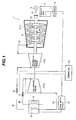
- Fig. 1 is a systematic diagram showing a power plant having a steam turbine according to the present embodiment.
- the power plant 1 includes a boiler 10, a steam turbine 2 (a high-pressure turbine 12, an intermediate-pressure turbine 14, and a low-pressure turbine 16), a generator 18 and a condenser 20.
- a rotor 2a of the low-pressure turbine 16 is connected to a drive shaft 22 of the generator 18.
- the generator 18 is driven by rotation of the low-pressure turbine 16 to generate electricity.
- the boiler 10 is a steam generator and has a reheater 24 therein.
- the boiler 10 is connected to an inlet side of the high-pressure turbine 12 through a tube 26.
- An outlet side of the high-pressure turbine 12 is connected to the reheater 24 of the boiler 10 through a tube 28.
- the reheater 24 is connected to an inlet side of the intermediate-pressure turbine 14 through a tube 30.
- An outlet side of the intermediate-pressure turbine 14 is connected to an inlet side of the low-pressure turbine 16 through a tube 32.
- Each of the tubes 26 and 30 has a control valve B.
- the control valve B of the tube 26 is controlled by a controller 54 and serves to control the amount of steam St to be introduced into the high-pressure turbine 12.
- the control valve B of the tube 30 is controlled by the controller 54 and serves to control the amount of steam St to be introduced into the intermediate-pressure turbine 14.
- the steam St generated by the boiler 10 is introduced into the low-pressure turbine 16 through the high-pressure turbine 12 and the intermediate-pressure turbine 14 to cause the rotor 2a provided in the low-pressure turbine 16 to rotate.
- the steam St that causes the rotor 2a to rotate and is discharged from the low-pressure turbine 16 is introduced into the condenser 20 through an exhaust hood 3.
- the steam St is then condensed and turned into water by the condenser 20. After that, the water is delivered to a feed water heater 21 and then heated by the feed water heater 21.
- the heated water is reintroduced into the boiler 10 (that is the steam generator) through another feed water heater (not shown), a high-pressure water pump (not shown) and the like.
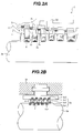
- Fig. 2A is a diagram showing the configuration of a part of the steam turbine.
- Fig. 2B is an enlarged view of an X portion shown in Fig. 2A .
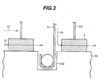
- Fig. 3 is an enlarged view of a Y portion shown in Fig. 2B .
- the steam St generated by the boiler 10 (refer to Fig. 1 ) is introduced into the casing 2d, the steam St expands and passes between the stator blades 2c and the rotor blades 2b alternately to cause the rotor 2a to rotate.
- the steam St passes through the rotor blade 2b located on the most downstream side of the rotor 2a, i.e., the last-stage rotor blade 2b, followed by being discharged outside of the casing 2d.
- the steam St flowing in the casing 2d causes the rotor blades 2b to efficiently rotate. It is therefore required to improve properties of seals between rotating portions (including the rotor 2a and the rotor blades 2b) and fixed portions (including the casing 2d and the stator blades 2c) and suppress the amount of steam leaking from clearances provided between the rotating portions and the fixed portions.
- a clearance is provided between the rotor 2a and each of nozzle diaphragm inner rings 3a.
- the nozzle diaphragm inner rings 3a allow for a rotational motion of the rotor 2a.
- the nozzle diaphragm inner rings 3a are located at tip portions of the stator blades 2c.
- the clearances may cause leakage of the steam St introduced in the stator blades 2c.
- a seal device such as a labyrinth seal device 3c is typically provided in the vicinity of the rotor 2a and of the nozzle diaphragm inner rings 3a to ensure that a clearance between the rotor 2a and each stator blade 2c is set to be small to improve the seal property.
- Fig. 2B is the enlarged view of the X portion shown in Fig. 2A and shows an example of the labyrinth seal device.
- a seal stationary body 3c1 having a plurality of seal fins 3c2 is engaged with and fixed to the nozzle diaphragm inner ring 3a.
- the seal stationary body 3c1 has grooves 3c3 arranged at a predetermined interval.
- the seal fins 3c2 are respectively caulked in and fixed to the grooves 3c3.
- the rotor 2a has grooves 2a2 arranged at a predetermined interval. Seal fins 2a1 are respectively caulked in and fixed to the grooves 2a2.
- the seal fins 3c2 and the seal fins 2a1 alternately overlap each other in the axial direction of the rotor 2a.
- the seal fins 3c2 are not in contact with the rotor 2a, and the seal fins 2a1 are not in contact with the seal stationary body 3c1.
- a sufficient clearance is provided between each of the seal fins 3c2 and the rotor 2a, and a sufficient clearance is provided between each of the seal fins 2a1 and the seal stationary body 3c1, to prevent a contact between each of the seal fins 3c2 and the rotor 2a and a contact between each of the seal fins 2a1 and the seal stationary body 3c1 and to thereby allow for a rotational motion of the rotor 2a.
- steam leaks from these clearances resulting in steam leakage loss. This reduces the efficiency of the steam turbine 2 (refer to Fig. 1 ).
- permeable spacers 4 made of permeable metal are provided between the respective seal fins 3c2 and the rotor 2a and between the respective seal fins 2a1 and the seal stationary body 3c1.
- the labyrinth seal device 3c shown in Fig. 2B is configured to ensure that the permeable spacers 4 face (are provided between) the rotor 2a and the respective seal fins 3c2 fixed to the seal stationary body 3c1, and the other permeable spacers 4 face (are provided between) the seal stationary body 3c1 and the respective seal fins 2a1 fixed to the rotor 2a.
- the permeable spacers 4 are provided on the rotor 2a (rotating portion) and face the seal fins 3c2, and the other permeable spacers 4 are provided on the seal stationary body 3c1 (fixed portion) and face the seal fins 2a1.
- the seal stationary body 3c1 is engaged with and fixed to the nozzle diaphragm inner rings 3a of the casing 2d.
- a method for setting the permeable spacers 4 on the rotor 2a and setting the permeable spacers 4 on the seal stationary body 3c1 is not limited.
- the permeable spacers 4 may be brazed on and fixed to the rotor 2a and the seal stationary body 3c1.
- the permeable spacers 4 are provided on the rotor 2a and along the circumference of the rotor 2a to ensure that the permeable spacers 4 respectively face tip portions of the seal fins 3c2.
- the technique is to remove or reduce a clearance between each seal fin 3c2 and the rotor 2a and a clearance between each seal fin 2a1 and the seal stationary body 3c1 for improvement of the seal property and provide a spacer (made of a material (such as an abradable material) having an excellent cutting property) on a portion (facing the tip portion of the seal fin 3c2) of the rotor 2a and provide a spacer (made of a material (such as an abradable material) having an excellent cutting property) on a portion (facing the seal fin 2a1) of the seal stationary body 3c1.
- a spacer made of a material (such as an abradable material) having an excellent cutting property
- a heat insulating material is provided between the seal fin 3c2 and the rotor 2a, and a heat insulating material is provided between the seal fin 2a1 and the seal stationary body 3c1.
- heat generated by a friction between the seal fin 3c2 and the spacer is gradually accumulated.
- the temperature of the heat insulating layer increases.
- the heat of the heat insulating layer is transferred to the rotor 2a.
- the temperature of the rotor 2a increases.
- the rotor 2a may be transformed (e.g., may be bent) by heat due to a nonuniform temperature distribution of the rotor 2a.
- the temperatures of the permeable spacers 4 are uniformly maintained to the same temperature as that of the steam St by the steam St (that passes through the inside of each permeable spacer 4). The temperatures of the permeable spacers 4 are not higher than that of the steam St.
- the amount of the steam St that passes through the inside of each permeable spacers 4 needs to be set to ensure that the seal property are not affected and the temperatures of the permeable spacers 4 are maintained to be the same as the temperature of the steam St.
- the amount of the steam St that passes through the permeable metal is extremely small, The amount of the steam St that passes through the permeable metal is determined based on the density and sizes of the pores. It is only necessary to use a permeable metal ensuring the steam amount that does not affect the seal property and allows the temperatures of the permeable spacers 4 to be maintained to the same level as the temperature of the steam St.
- the temperatures of the permeable spacers 4 are maintained to be the same as the temperature of the steam St, the temperatures of the permeable spacers 4 do not become higher than the temperature of the steam St even when the rotor 2a continuously rotates for a long period of time and the seal fins 3c2 are in contact with the permeable spacers 4 (that rotate with the rotor 2a) for a long period of time.
- This configuration can suppress an increase in the temperature of the rotor 2a to a level higher than the temperature of the steam St.
- the rotor 2a is designed to be resistant to the temperature of the steam St.
- the amount of the steam St that passes through each permeable spacer 4 is small compared with the amount of the steam leaking from the clearance provided between each seal fin 3c2 and the rotor 2a.
- the amount of the steam St that passes through each permeable spacer 4 does not affect the turbine efficiency of the steam turbine 2 (refer to Fig. 1 )
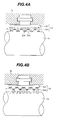
- the labyrinth seal device 3c may be a high-low labyrinth seal device in addition to the configuration shown in Fig. 2B .
- the present invention can be applied to the high-low labyrinth seal device.
- Figs. 4A and 4B are diagrams each showing a high-low labyrinth seal device.
- Fig. 4A shows the high-low labyrinth seal device in which the seal stationary body has seal fins.
- Fig. 4B shows the high-low labyrinth seal device in which the rotor has seal fins.
- the seal stationary body 3c1 of the high-low labyrinth seal device 3c shown in Fig. 4A has a plurality of the seal fins 3c4.
- the labyrinth seal device 3c shown in Fig. 4A is engaged with and fixed to the nozzle diaphragm inner ring 3a.
- the rotor 2a shown in Fig. 4A has a plurality of protruding portions 2a3 and recessed portions 2a4.
- the protruding portions 2a3 are provided at a circumferential portion of the rotor 2a.
- Each of the recessed portions 2a4 is located between the protruding portions 2a3.
- the seal fins 3c4 face the respective protruding portions 2a3 of the rotor 2a and recessed portions 2a4.
- the air-permeable spacers 4 are provided on the protruding portions 2a3 of the rotor 2a and on the recessed portions 2a4 of the rotor 2a and face the respective seal fins 3c4.
- the permeable spacers 4 can serve to improve the seal property between the seal fins 3c4 and the rotor 2a.
- the permeable spacers 4 may be provided on either the protruding portions 2a3 of the rotor 2a or the recessed portions 2a4 of the rotor 2a in the high-low labyrinth seal device 3c,
- the high-low labyrinth seal device 3c may have a structure in which the seal fins 2a5 are provided at the circumferential portion of the rotor 2a.
- the seal stationary body 3c1 has recessed portions and protruding portions. The recessed portions and protruding portions of the seal stationary body 3c1 face the respective seal fins 2a5.
- the permeable spacers 4 are provided on the recessed portions and protruding portions of the seal stationary body 3c1.
- the permeable spacers 4 may be provided on either the recessed portions of the seal stationary body 3c1 or the protruding portions of the seal stationary body 3c1.
- the permeable spacers 4 are provided for the labyrinth seal device 3c that is located between the stator blade 2c and the rotor 2a, as shown in Fig. 2A .
- the permeable spacers 4 may be provided at a tip portion of each rotor blade 2b.
- the permeable spacers 4 are provided on the cover 2g and face the respective seal fins 3b1.
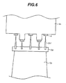
- the seal fins may be provided at the tip portion of each rotor blade.
- Fig. 6 is a diagram showing a structure in which the seal fins are provided at the tip portion of the rotor blade.
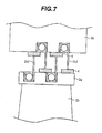
- Fig. 7 is a diagram showing a structure in which the seal fins are provided on the nozzle diaphragm outer ring and the seal fins are provided at the tip portion of the rotor blade.
- the seal fins 2b1 may be provided at the tip portion of each rotor blade 2b (or on the cover 2g).
- the permeable spacers 4 are provided on the nozzle diaphragm outer ring 3b and face the respective seal fins 2b1.
- the seal fins 3b2 may be provided on the nozzle diaphragm outer ring 3b, and the seal fins 2b2 may be provided at the tip portion of each rotor blade 2b.
- the permeable spacers 4 are provided on the nozzle diaphragm outer ring 3b, and the other permeable spacers 4 are provided at the tip portion of each rotor blade 2b (or on the cover 2g).
- the permeable spacers 4 may be provided either on the nozzle diaphragm outer ring 3b or at the tip portion of each rotor blade 2b (or on the cover 2g).
- the permeable spacers 4 may be provided at locations at which a rotating portion (such as the rotor 2a (refer to Fig. 2A ) and a fixed portion (such as the casing 2d (refer to Fig. 2A ) are in contact with each other. It is possible to improve the seal property since the rotating portion is not subjected to high temperature steam.
- the amount of the steam that passes through the permeable spacers 4 can be properly set in consideration of the seal property and a cooling property.
Landscapes
- Engineering & Computer Science (AREA)
- General Engineering & Computer Science (AREA)
- Mechanical Engineering (AREA)
- Turbine Rotor Nozzle Sealing (AREA)
- Sealing Using Fluids, Sealing Without Contact, And Removal Of Oil (AREA)
Applications Claiming Priority (2)
| Application Number | Priority Date | Filing Date | Title |
|---|---|---|---|
| JP2007313803A JP4668976B2 (ja) | 2007-12-04 | 2007-12-04 | 蒸気タービンのシール構造 |
| EP08170392A EP2067930B1 (de) | 2007-12-04 | 2008-12-01 | Dichtung für eine Dampfturbine |
Related Parent Applications (2)
| Application Number | Title | Priority Date | Filing Date |
|---|---|---|---|
| EP08170392.8 Division | 2008-12-01 | ||
| EP08170392A Division EP2067930B1 (de) | 2007-12-04 | 2008-12-01 | Dichtung für eine Dampfturbine |
Publications (2)
| Publication Number | Publication Date |
|---|---|
| EP2372103A1 true EP2372103A1 (de) | 2011-10-05 |
| EP2372103B1 EP2372103B1 (de) | 2015-04-15 |
Family
ID=40675897
Family Applications (2)
| Application Number | Title | Priority Date | Filing Date |
|---|---|---|---|
| EP08170392A Not-in-force EP2067930B1 (de) | 2007-12-04 | 2008-12-01 | Dichtung für eine Dampfturbine |
| EP11171614.8A Not-in-force EP2372103B1 (de) | 2007-12-04 | 2008-12-01 | Dichtungsanordnung für eine Dampfturbine |
Family Applications Before (1)
| Application Number | Title | Priority Date | Filing Date |
|---|---|---|---|
| EP08170392A Not-in-force EP2067930B1 (de) | 2007-12-04 | 2008-12-01 | Dichtung für eine Dampfturbine |
Country Status (5)
| Country | Link |
|---|---|
| US (2) | US8128351B2 (de) |
| EP (2) | EP2067930B1 (de) |
| JP (1) | JP4668976B2 (de) |
| AT (1) | ATE516422T1 (de) |
| ES (1) | ES2540552T3 (de) |
Cited By (2)
| Publication number | Priority date | Publication date | Assignee | Title |
|---|---|---|---|---|
| CN104024581A (zh) * | 2011-12-13 | 2014-09-03 | 三菱日立电力系统株式会社 | 涡轮 |
| EP2246524A3 (de) * | 2009-05-01 | 2017-10-18 | Mitsubishi Hitachi Power Systems, Ltd. | Dichtsystem und Steuerverfahren dafür |
Families Citing this family (19)
| Publication number | Priority date | Publication date | Assignee | Title |
|---|---|---|---|---|
| JP4668976B2 (ja) * | 2007-12-04 | 2011-04-13 | 株式会社日立製作所 | 蒸気タービンのシール構造 |
| JP5210984B2 (ja) | 2009-06-29 | 2013-06-12 | 株式会社日立製作所 | タービン用高信頼性メタルシール材 |
| DE102009042857A1 (de) * | 2009-09-24 | 2011-03-31 | Rolls-Royce Deutschland Ltd & Co Kg | Gasturbine mit Deckband-Labyrinthdichtung |
| US8864443B2 (en) | 2010-07-14 | 2014-10-21 | Hitachi, Ltd. | Sealing device for steam turbines and method for controlling sealing device |
| US20120067054A1 (en) | 2010-09-21 | 2012-03-22 | Palmer Labs, Llc | High efficiency power production methods, assemblies, and systems |
| US20120076642A1 (en) * | 2010-09-23 | 2012-03-29 | Chiu Ya-Tien | Sealing assembly for use in turbomachines and method of assembling same |
| WO2012116943A1 (de) * | 2011-02-28 | 2012-09-07 | Alstom Technology Ltd | Turbine mit dichtungseinrichtung zwischen leitschaufelträger und gehäuse |
| JP5774963B2 (ja) * | 2011-10-21 | 2015-09-09 | 三菱重工業株式会社 | シール装置 |
| EP2647796A1 (de) * | 2012-04-04 | 2013-10-09 | MTU Aero Engines GmbH | Dichtungssystem für eine Strömungsmaschine |
| EP2647795B1 (de) * | 2012-04-04 | 2018-11-07 | MTU Aero Engines AG | Dichtungssystem für eine Strömungsmaschine |
| JP5892880B2 (ja) * | 2012-07-03 | 2016-03-23 | 三菱日立パワーシステムズ株式会社 | 回転機械のシール構造及び回転機械 |
| CN104903547B (zh) * | 2012-12-13 | 2016-09-21 | 三菱日立电力系统株式会社 | 旋转流体机械 |
| DE102013017710A1 (de) * | 2013-10-24 | 2015-04-30 | Man Diesel & Turbo Se | Dichtungssystem |
| JP2016089768A (ja) * | 2014-11-07 | 2016-05-23 | 三菱日立パワーシステムズ株式会社 | シール装置及びターボ機械 |
| KR101695125B1 (ko) * | 2016-01-11 | 2017-01-10 | 두산중공업 주식회사 | 터빈의 다단 실링 구조 |
| US10598038B2 (en) * | 2017-11-21 | 2020-03-24 | Honeywell International Inc. | Labyrinth seal with variable tooth heights |
| KR102004648B1 (ko) * | 2018-02-26 | 2019-07-26 | 두산중공업 주식회사 | 자기장 통신을 이용한 증기터빈 실 패킹 성능 감시 시스템 |
| KR102088969B1 (ko) * | 2018-10-23 | 2020-03-16 | 진영티비엑스(주) | 라비린스 씰 어셈블리 |
| JP6808872B1 (ja) * | 2020-04-28 | 2021-01-06 | 三菱パワー株式会社 | シール装置及び回転機械 |
Citations (11)
| Publication number | Priority date | Publication date | Assignee | Title |
|---|---|---|---|---|
| US3411794A (en) * | 1966-12-12 | 1968-11-19 | Gen Motors Corp | Cooled seal ring |
| FR1547085A (fr) * | 1966-12-12 | 1968-11-22 | Gen Motors Corp | Matériau métallique cellulaire |
| DE19750516A1 (de) * | 1997-11-14 | 1999-05-20 | Asea Brown Boveri | Abreibbare Dichtung |
| EP1076157A2 (de) * | 1999-08-09 | 2001-02-14 | ALSTOM POWER (Schweiz) AG | Reibungskomponente einer thermischen Turbomaschine |
| JP2002228013A (ja) | 2001-02-01 | 2002-08-14 | Mitsubishi Heavy Ind Ltd | Acc型ラビリンスシール |
| WO2003010419A1 (de) * | 2001-07-23 | 2003-02-06 | Alstom Technology Ltd | Vorrichtung zur dichtspaltreduzierung zwischen bewegten und stationären komponenten innerhalb einer strömungsmaschine |
| WO2003052240A2 (de) * | 2001-12-14 | 2003-06-26 | Alstom Technology Ltd | Gasturbinenanordnung |
| WO2003054360A1 (de) * | 2001-12-13 | 2003-07-03 | Alstom Technology Ltd | Heissgaspfad-baugruppe einer gasturbine |
| EP1496140A1 (de) * | 2003-07-09 | 2005-01-12 | Siemens Aktiengesellschaft | Schichtstruktur und Verfahren zur Herstellung einer Schichtstruktur |
| WO2005061855A1 (de) * | 2003-12-20 | 2005-07-07 | Mtu Aero Engines Gmbh | Gasturbinenbauteil |
| JP2007016704A (ja) | 2005-07-08 | 2007-01-25 | Mitsubishi Heavy Ind Ltd | 回転軸のシール構造及びこれを有する回転機械 |
Family Cites Families (16)
| Publication number | Priority date | Publication date | Assignee | Title |
|---|---|---|---|---|
| JPS5920908B2 (ja) * | 1977-07-21 | 1984-05-16 | 住友電気工業株式会社 | ラビリンスパツキン |
| US4257735A (en) * | 1978-12-15 | 1981-03-24 | General Electric Company | Gas turbine engine seal and method for making same |
| JPS55101755A (en) | 1979-01-26 | 1980-08-04 | Hitachi Ltd | Altitude adjuster for exhaust recirculation |
| DE3579684D1 (de) * | 1984-12-24 | 1990-10-18 | United Technologies Corp | Abschleifbare dichtung mit besonderem erosionswiderstand. |
| US4657171A (en) * | 1985-06-13 | 1987-04-14 | General Electric Company | Repair of a member having a projection |
| JP3898785B2 (ja) * | 1996-09-24 | 2007-03-28 | 株式会社日立製作所 | 高低圧一体型蒸気タービン用動翼と高低圧一体型蒸気タービン及びコンバインド発電システム並びに複合発電プラント |
| KR100258419B1 (ko) | 1997-11-03 | 2000-07-01 | 한승희 | 탈모를예방하는모발용화장조성물및그조성물의제조방법 |
| EP1152124A1 (de) * | 2000-05-04 | 2001-11-07 | Siemens Aktiengesellschaft | Dichtungsanordnung |
| US6574966B2 (en) * | 2000-06-08 | 2003-06-10 | Hitachi, Ltd. | Gas turbine for power generation |
| US6547522B2 (en) * | 2001-06-18 | 2003-04-15 | General Electric Company | Spring-backed abradable seal for turbomachinery |
| US7287956B2 (en) * | 2004-12-22 | 2007-10-30 | General Electric Company | Removable abradable seal carriers for sealing between rotary and stationary turbine components |
| JP4718991B2 (ja) * | 2005-12-22 | 2011-07-06 | 株式会社東芝 | シール装置 |
| GB0613715D0 (en) * | 2006-07-11 | 2006-08-23 | Rolls Royce Plc | A seal between relatively moveable members |
| US8540479B2 (en) | 2007-01-11 | 2013-09-24 | General Electric Company | Active retractable seal for turbo machinery and related method |
| JP4668976B2 (ja) * | 2007-12-04 | 2011-04-13 | 株式会社日立製作所 | 蒸気タービンのシール構造 |
| JP5411569B2 (ja) * | 2009-05-01 | 2014-02-12 | 株式会社日立製作所 | シール構造とその制御方法 |
-
2007
- 2007-12-04 JP JP2007313803A patent/JP4668976B2/ja not_active Expired - Fee Related
-
2008
- 2008-12-01 EP EP08170392A patent/EP2067930B1/de not_active Not-in-force
- 2008-12-01 AT AT08170392T patent/ATE516422T1/de not_active IP Right Cessation
- 2008-12-01 ES ES11171614.8T patent/ES2540552T3/es active Active
- 2008-12-01 EP EP11171614.8A patent/EP2372103B1/de not_active Not-in-force
- 2008-12-02 US US12/326,216 patent/US8128351B2/en not_active Expired - Fee Related
-
2012
- 2012-02-14 US US13/396,033 patent/US8500397B2/en not_active Expired - Fee Related
Patent Citations (11)
| Publication number | Priority date | Publication date | Assignee | Title |
|---|---|---|---|---|
| US3411794A (en) * | 1966-12-12 | 1968-11-19 | Gen Motors Corp | Cooled seal ring |
| FR1547085A (fr) * | 1966-12-12 | 1968-11-22 | Gen Motors Corp | Matériau métallique cellulaire |
| DE19750516A1 (de) * | 1997-11-14 | 1999-05-20 | Asea Brown Boveri | Abreibbare Dichtung |
| EP1076157A2 (de) * | 1999-08-09 | 2001-02-14 | ALSTOM POWER (Schweiz) AG | Reibungskomponente einer thermischen Turbomaschine |
| JP2002228013A (ja) | 2001-02-01 | 2002-08-14 | Mitsubishi Heavy Ind Ltd | Acc型ラビリンスシール |
| WO2003010419A1 (de) * | 2001-07-23 | 2003-02-06 | Alstom Technology Ltd | Vorrichtung zur dichtspaltreduzierung zwischen bewegten und stationären komponenten innerhalb einer strömungsmaschine |
| WO2003054360A1 (de) * | 2001-12-13 | 2003-07-03 | Alstom Technology Ltd | Heissgaspfad-baugruppe einer gasturbine |
| WO2003052240A2 (de) * | 2001-12-14 | 2003-06-26 | Alstom Technology Ltd | Gasturbinenanordnung |
| EP1496140A1 (de) * | 2003-07-09 | 2005-01-12 | Siemens Aktiengesellschaft | Schichtstruktur und Verfahren zur Herstellung einer Schichtstruktur |
| WO2005061855A1 (de) * | 2003-12-20 | 2005-07-07 | Mtu Aero Engines Gmbh | Gasturbinenbauteil |
| JP2007016704A (ja) | 2005-07-08 | 2007-01-25 | Mitsubishi Heavy Ind Ltd | 回転軸のシール構造及びこれを有する回転機械 |
Cited By (4)
| Publication number | Priority date | Publication date | Assignee | Title |
|---|---|---|---|---|
| EP2246524A3 (de) * | 2009-05-01 | 2017-10-18 | Mitsubishi Hitachi Power Systems, Ltd. | Dichtsystem und Steuerverfahren dafür |
| CN104024581A (zh) * | 2011-12-13 | 2014-09-03 | 三菱日立电力系统株式会社 | 涡轮 |
| CN104024581B (zh) * | 2011-12-13 | 2016-04-13 | 三菱日立电力系统株式会社 | 涡轮 |
| US10006292B2 (en) | 2011-12-13 | 2018-06-26 | Mitsubishi Hitachi Power Systems, Ltd. | Turbine |
Also Published As
| Publication number | Publication date |
|---|---|
| EP2067930A2 (de) | 2009-06-10 |
| JP2009138566A (ja) | 2009-06-25 |
| US8500397B2 (en) | 2013-08-06 |
| US20090142187A1 (en) | 2009-06-04 |
| ES2540552T3 (es) | 2015-07-10 |
| JP4668976B2 (ja) | 2011-04-13 |
| EP2067930B1 (de) | 2011-07-13 |
| ATE516422T1 (de) | 2011-07-15 |
| US8128351B2 (en) | 2012-03-06 |
| US20120148389A1 (en) | 2012-06-14 |
| EP2372103B1 (de) | 2015-04-15 |
| EP2067930A3 (de) | 2010-06-30 |
Similar Documents
| Publication | Publication Date | Title |
|---|---|---|
| EP2372103A1 (de) | Dichtungsanordnung für eine Dampfturbine | |
| EP2246524A2 (de) | Dichtsystem und Steuerverfahren dafür | |
| CN100590297C (zh) | 用于蒸汽涡轮机的膨胀密封条 | |
| JP5695330B2 (ja) | タービンエンジンの冷却空気を管理するための装置 | |
| JP2011094615A (ja) | タービンロータブレード先端及びシュラウドのクリアランス制御 | |
| US8678753B2 (en) | Passive flow control through turbine engine | |
| EP2410134A1 (de) | Dichtungsvorrichtung für Dampfturbinen und Verfahren zur Steuerung der Dichtungsvorrichtung | |
| JP2011094626A (ja) | タービンエンジン冷却のための装置及び方法 | |
| JP2010038101A (ja) | 蒸気タービンおよび蒸気タービンプラントシステム | |
| JP2004332736A (ja) | タービン内部をシールするのを可能にするための方法及び装置 | |
| JP2010019261A (ja) | タービンダブテール用のスプリングシール | |
| JP2011140943A (ja) | 逆圧力勾配シール機構 | |
| US9228588B2 (en) | Turbomachine component temperature control | |
| US10208609B2 (en) | Turbine and methods of assembling the same | |
| JP2016196885A (ja) | ターボ機械のホイール及びバケットのためのヒートパイプ温度管理システム | |
| JP6637455B2 (ja) | 蒸気タービン | |
| US10041367B2 (en) | Axially faced seal system | |
| EP2653662A1 (de) | Mica-basierte Dichtungen für eine Halteklammer einer Gasturbinenummantelung | |
| JP5087147B2 (ja) | 蒸気タービン | |
| JP2018127919A (ja) | 蒸気タービンシステム | |
| JP2009002188A (ja) | タービンの熱出力増大方法及びタービン構造 | |
| EP1748156A2 (de) | Wellenabdichtung in einer geothermischen Dampfturbine | |
| Wisniewski | EthosEnergy modernization package for HP part of 200MW steam turbine of LMZ design. Case study | |
| JP2018135837A (ja) | 蒸気タービンプラント | |
| JP2004346805A (ja) | タービンロータ及びタービンステータの製作方法 |
Legal Events
| Date | Code | Title | Description |
|---|---|---|---|
| PUAI | Public reference made under article 153(3) epc to a published international application that has entered the european phase |
Free format text: ORIGINAL CODE: 0009012 |
|
| 17P | Request for examination filed |
Effective date: 20110712 |
|
| AC | Divisional application: reference to earlier application |
Ref document number: 2067930 Country of ref document: EP Kind code of ref document: P |
|
| AK | Designated contracting states |
Kind code of ref document: A1 Designated state(s): AT BE BG CH CY CZ DE DK EE ES FI FR GB GR HR HU IE IS IT LI LT LU LV MC MT NL NO PL PT RO SE SI SK TR |
|
| RIC1 | Information provided on ipc code assigned before grant |
Ipc: F01D 11/08 20060101ALI20120228BHEP Ipc: F16J 15/16 20060101ALI20120228BHEP Ipc: F01D 11/02 20060101ALI20120228BHEP Ipc: F01D 11/00 20060101AFI20120228BHEP Ipc: F16J 15/447 20060101ALI20120228BHEP |
|
| 17Q | First examination report despatched |
Effective date: 20120328 |
|
| GRAP | Despatch of communication of intention to grant a patent |
Free format text: ORIGINAL CODE: EPIDOSNIGR1 |
|
| INTG | Intention to grant announced |
Effective date: 20141104 |
|
| RIN1 | Information on inventor provided before grant (corrected) |
Inventor name: NARITA, KENJIRO Inventor name: TORIYA, HAJIME Inventor name: YAMAZAKI, HARUYUKI Inventor name: DOI, HIROYUKI Inventor name: KOBAYASHI, KEI |
|
| RAP1 | Party data changed (applicant data changed or rights of an application transferred) |
Owner name: MITSUBISHI HITACHI POWER SYSTEMS, LTD. |
|
| GRAS | Grant fee paid |
Free format text: ORIGINAL CODE: EPIDOSNIGR3 |
|
| GRAA | (expected) grant |
Free format text: ORIGINAL CODE: 0009210 |
|
| AC | Divisional application: reference to earlier application |
Ref document number: 2067930 Country of ref document: EP Kind code of ref document: P |
|
| AK | Designated contracting states |
Kind code of ref document: B1 Designated state(s): AT BE BG CH CY CZ DE DK EE ES FI FR GB GR HR HU IE IS IT LI LT LU LV MC MT NL NO PL PT RO SE SI SK TR |
|
| RAP1 | Party data changed (applicant data changed or rights of an application transferred) |
Owner name: MITSUBISHI HITACHI POWER SYSTEMS, LTD. |
|
| REG | Reference to a national code |
Ref country code: GB Ref legal event code: FG4D Ref country code: CH Ref legal event code: EP |
|
| REG | Reference to a national code |
Ref country code: IE Ref legal event code: FG4D |
|
| REG | Reference to a national code |
Ref country code: AT Ref legal event code: REF Ref document number: 722114 Country of ref document: AT Kind code of ref document: T Effective date: 20150515 |
|
| REG | Reference to a national code |
Ref country code: DE Ref legal event code: R096 Ref document number: 602008037749 Country of ref document: DE Effective date: 20150528 |
|
| REG | Reference to a national code |
Ref country code: ES Ref legal event code: FG2A Ref document number: 2540552 Country of ref document: ES Kind code of ref document: T3 Effective date: 20150710 |
|
| REG | Reference to a national code |
Ref country code: SE Ref legal event code: TRGR |
|
| REG | Reference to a national code |
Ref country code: AT Ref legal event code: MK05 Ref document number: 722114 Country of ref document: AT Kind code of ref document: T Effective date: 20150415 |
|
| REG | Reference to a national code |
Ref country code: LT Ref legal event code: MG4D |
|
| PG25 | Lapsed in a contracting state [announced via postgrant information from national office to epo] |
Ref country code: NO Free format text: LAPSE BECAUSE OF FAILURE TO SUBMIT A TRANSLATION OF THE DESCRIPTION OR TO PAY THE FEE WITHIN THE PRESCRIBED TIME-LIMIT Effective date: 20150715 Ref country code: LT Free format text: LAPSE BECAUSE OF FAILURE TO SUBMIT A TRANSLATION OF THE DESCRIPTION OR TO PAY THE FEE WITHIN THE PRESCRIBED TIME-LIMIT Effective date: 20150415 Ref country code: PT Free format text: LAPSE BECAUSE OF FAILURE TO SUBMIT A TRANSLATION OF THE DESCRIPTION OR TO PAY THE FEE WITHIN THE PRESCRIBED TIME-LIMIT Effective date: 20150817 Ref country code: HR Free format text: LAPSE BECAUSE OF FAILURE TO SUBMIT A TRANSLATION OF THE DESCRIPTION OR TO PAY THE FEE WITHIN THE PRESCRIBED TIME-LIMIT Effective date: 20150415 Ref country code: FI Free format text: LAPSE BECAUSE OF FAILURE TO SUBMIT A TRANSLATION OF THE DESCRIPTION OR TO PAY THE FEE WITHIN THE PRESCRIBED TIME-LIMIT Effective date: 20150415 |
|
| PG25 | Lapsed in a contracting state [announced via postgrant information from national office to epo] |
Ref country code: IS Free format text: LAPSE BECAUSE OF FAILURE TO SUBMIT A TRANSLATION OF THE DESCRIPTION OR TO PAY THE FEE WITHIN THE PRESCRIBED TIME-LIMIT Effective date: 20150815 Ref country code: AT Free format text: LAPSE BECAUSE OF FAILURE TO SUBMIT A TRANSLATION OF THE DESCRIPTION OR TO PAY THE FEE WITHIN THE PRESCRIBED TIME-LIMIT Effective date: 20150415 Ref country code: GR Free format text: LAPSE BECAUSE OF FAILURE TO SUBMIT A TRANSLATION OF THE DESCRIPTION OR TO PAY THE FEE WITHIN THE PRESCRIBED TIME-LIMIT Effective date: 20150716 Ref country code: LV Free format text: LAPSE BECAUSE OF FAILURE TO SUBMIT A TRANSLATION OF THE DESCRIPTION OR TO PAY THE FEE WITHIN THE PRESCRIBED TIME-LIMIT Effective date: 20150415 |
|
| REG | Reference to a national code |
Ref country code: FR Ref legal event code: PLFP Year of fee payment: 8 |
|
| REG | Reference to a national code |
Ref country code: DE Ref legal event code: R097 Ref document number: 602008037749 Country of ref document: DE |
|
| PG25 | Lapsed in a contracting state [announced via postgrant information from national office to epo] |
Ref country code: DK Free format text: LAPSE BECAUSE OF FAILURE TO SUBMIT A TRANSLATION OF THE DESCRIPTION OR TO PAY THE FEE WITHIN THE PRESCRIBED TIME-LIMIT Effective date: 20150415 Ref country code: EE Free format text: LAPSE BECAUSE OF FAILURE TO SUBMIT A TRANSLATION OF THE DESCRIPTION OR TO PAY THE FEE WITHIN THE PRESCRIBED TIME-LIMIT Effective date: 20150415 |
|
| PLBE | No opposition filed within time limit |
Free format text: ORIGINAL CODE: 0009261 |
|
| STAA | Information on the status of an ep patent application or granted ep patent |
Free format text: STATUS: NO OPPOSITION FILED WITHIN TIME LIMIT |
|
| PG25 | Lapsed in a contracting state [announced via postgrant information from national office to epo] |
Ref country code: RO Free format text: LAPSE BECAUSE OF NON-PAYMENT OF DUE FEES Effective date: 20150415 Ref country code: CZ Free format text: LAPSE BECAUSE OF FAILURE TO SUBMIT A TRANSLATION OF THE DESCRIPTION OR TO PAY THE FEE WITHIN THE PRESCRIBED TIME-LIMIT Effective date: 20150415 Ref country code: SK Free format text: LAPSE BECAUSE OF FAILURE TO SUBMIT A TRANSLATION OF THE DESCRIPTION OR TO PAY THE FEE WITHIN THE PRESCRIBED TIME-LIMIT Effective date: 20150415 Ref country code: PL Free format text: LAPSE BECAUSE OF FAILURE TO SUBMIT A TRANSLATION OF THE DESCRIPTION OR TO PAY THE FEE WITHIN THE PRESCRIBED TIME-LIMIT Effective date: 20150415 |
|
| 26N | No opposition filed |
Effective date: 20160118 |
|
| PG25 | Lapsed in a contracting state [announced via postgrant information from national office to epo] |
Ref country code: BE Free format text: LAPSE BECAUSE OF NON-PAYMENT OF DUE FEES Effective date: 20151231 Ref country code: SI Free format text: LAPSE BECAUSE OF FAILURE TO SUBMIT A TRANSLATION OF THE DESCRIPTION OR TO PAY THE FEE WITHIN THE PRESCRIBED TIME-LIMIT Effective date: 20150415 |
|
| PG25 | Lapsed in a contracting state [announced via postgrant information from national office to epo] |
Ref country code: MC Free format text: LAPSE BECAUSE OF FAILURE TO SUBMIT A TRANSLATION OF THE DESCRIPTION OR TO PAY THE FEE WITHIN THE PRESCRIBED TIME-LIMIT Effective date: 20150415 Ref country code: LU Free format text: LAPSE BECAUSE OF FAILURE TO SUBMIT A TRANSLATION OF THE DESCRIPTION OR TO PAY THE FEE WITHIN THE PRESCRIBED TIME-LIMIT Effective date: 20151201 |
|
| PG25 | Lapsed in a contracting state [announced via postgrant information from national office to epo] |
Ref country code: BE Free format text: LAPSE BECAUSE OF FAILURE TO SUBMIT A TRANSLATION OF THE DESCRIPTION OR TO PAY THE FEE WITHIN THE PRESCRIBED TIME-LIMIT Effective date: 20150415 |
|
| REG | Reference to a national code |
Ref country code: IE Ref legal event code: MM4A |
|
| PG25 | Lapsed in a contracting state [announced via postgrant information from national office to epo] |
Ref country code: IE Free format text: LAPSE BECAUSE OF NON-PAYMENT OF DUE FEES Effective date: 20151201 |
|
| REG | Reference to a national code |
Ref country code: FR Ref legal event code: PLFP Year of fee payment: 9 |
|
| PG25 | Lapsed in a contracting state [announced via postgrant information from national office to epo] |
Ref country code: HU Free format text: LAPSE BECAUSE OF FAILURE TO SUBMIT A TRANSLATION OF THE DESCRIPTION OR TO PAY THE FEE WITHIN THE PRESCRIBED TIME-LIMIT; INVALID AB INITIO Effective date: 20081201 Ref country code: BG Free format text: LAPSE BECAUSE OF FAILURE TO SUBMIT A TRANSLATION OF THE DESCRIPTION OR TO PAY THE FEE WITHIN THE PRESCRIBED TIME-LIMIT Effective date: 20150415 |
|
| PG25 | Lapsed in a contracting state [announced via postgrant information from national office to epo] |
Ref country code: CY Free format text: LAPSE BECAUSE OF FAILURE TO SUBMIT A TRANSLATION OF THE DESCRIPTION OR TO PAY THE FEE WITHIN THE PRESCRIBED TIME-LIMIT Effective date: 20150415 |
|
| PG25 | Lapsed in a contracting state [announced via postgrant information from national office to epo] |
Ref country code: MT Free format text: LAPSE BECAUSE OF FAILURE TO SUBMIT A TRANSLATION OF THE DESCRIPTION OR TO PAY THE FEE WITHIN THE PRESCRIBED TIME-LIMIT Effective date: 20150415 Ref country code: TR Free format text: LAPSE BECAUSE OF FAILURE TO SUBMIT A TRANSLATION OF THE DESCRIPTION OR TO PAY THE FEE WITHIN THE PRESCRIBED TIME-LIMIT Effective date: 20150415 |
|
| REG | Reference to a national code |
Ref country code: FR Ref legal event code: PLFP Year of fee payment: 10 |
|
| PGFP | Annual fee paid to national office [announced via postgrant information from national office to epo] |
Ref country code: DE Payment date: 20171129 Year of fee payment: 10 Ref country code: FR Payment date: 20171113 Year of fee payment: 10 Ref country code: NL Payment date: 20171115 Year of fee payment: 10 |
|
| PGFP | Annual fee paid to national office [announced via postgrant information from national office to epo] |
Ref country code: GB Payment date: 20171129 Year of fee payment: 10 Ref country code: SE Payment date: 20171213 Year of fee payment: 10 Ref country code: CH Payment date: 20171212 Year of fee payment: 10 |
|
| PGFP | Annual fee paid to national office [announced via postgrant information from national office to epo] |
Ref country code: ES Payment date: 20180104 Year of fee payment: 10 |
|
| PGFP | Annual fee paid to national office [announced via postgrant information from national office to epo] |
Ref country code: IT Payment date: 20171221 Year of fee payment: 10 |
|
| REG | Reference to a national code |
Ref country code: DE Ref legal event code: R119 Ref document number: 602008037749 Country of ref document: DE |
|
| REG | Reference to a national code |
Ref country code: SE Ref legal event code: EUG |
|
| PG25 | Lapsed in a contracting state [announced via postgrant information from national office to epo] |
Ref country code: SE Free format text: LAPSE BECAUSE OF NON-PAYMENT OF DUE FEES Effective date: 20181202 |
|
| REG | Reference to a national code |
Ref country code: CH Ref legal event code: PL |
|
| REG | Reference to a national code |
Ref country code: NL Ref legal event code: MM Effective date: 20190101 |
|
| GBPC | Gb: european patent ceased through non-payment of renewal fee |
Effective date: 20181201 |
|
| PG25 | Lapsed in a contracting state [announced via postgrant information from national office to epo] |
Ref country code: NL Free format text: LAPSE BECAUSE OF NON-PAYMENT OF DUE FEES Effective date: 20190101 |
|
| PG25 | Lapsed in a contracting state [announced via postgrant information from national office to epo] |
Ref country code: IT Free format text: LAPSE BECAUSE OF NON-PAYMENT OF DUE FEES Effective date: 20181201 Ref country code: DE Free format text: LAPSE BECAUSE OF NON-PAYMENT OF DUE FEES Effective date: 20190702 Ref country code: FR Free format text: LAPSE BECAUSE OF NON-PAYMENT OF DUE FEES Effective date: 20181231 |
|
| PG25 | Lapsed in a contracting state [announced via postgrant information from national office to epo] |
Ref country code: CH Free format text: LAPSE BECAUSE OF NON-PAYMENT OF DUE FEES Effective date: 20181231 Ref country code: GB Free format text: LAPSE BECAUSE OF NON-PAYMENT OF DUE FEES Effective date: 20181201 Ref country code: LI Free format text: LAPSE BECAUSE OF NON-PAYMENT OF DUE FEES Effective date: 20181231 |
|
| REG | Reference to a national code |
Ref country code: ES Ref legal event code: FD2A Effective date: 20200131 |
|
| PG25 | Lapsed in a contracting state [announced via postgrant information from national office to epo] |
Ref country code: ES Free format text: LAPSE BECAUSE OF NON-PAYMENT OF DUE FEES Effective date: 20181202 |