EP2371619B1 - Seat adjusting apparatus for vehicle - Google Patents
Seat adjusting apparatus for vehicle Download PDFInfo
- Publication number
- EP2371619B1 EP2371619B1 EP11157256A EP11157256A EP2371619B1 EP 2371619 B1 EP2371619 B1 EP 2371619B1 EP 11157256 A EP11157256 A EP 11157256A EP 11157256 A EP11157256 A EP 11157256A EP 2371619 B1 EP2371619 B1 EP 2371619B1
- Authority
- EP
- European Patent Office
- Prior art keywords
- pinion gear
- bearing
- gear
- tooth
- sector gear
- Prior art date
- Legal status (The legal status is an assumption and is not a legal conclusion. Google has not performed a legal analysis and makes no representation as to the accuracy of the status listed.)
- Active
Links
- 230000007246 mechanism Effects 0.000 claims description 29
- 230000033001 locomotion Effects 0.000 description 17
- 230000005540 biological transmission Effects 0.000 description 10
- 230000005484 gravity Effects 0.000 description 4
- 230000009467 reduction Effects 0.000 description 3
- 230000004044 response Effects 0.000 description 3
- 230000000694 effects Effects 0.000 description 2
- ZPUCINDJVBIVPJ-LJISPDSOSA-N cocaine Chemical compound O([C@H]1C[C@@H]2CC[C@@H](N2C)[C@H]1C(=O)OC)C(=O)C1=CC=CC=C1 ZPUCINDJVBIVPJ-LJISPDSOSA-N 0.000 description 1
- 238000000034 method Methods 0.000 description 1
- 230000008569 process Effects 0.000 description 1
- 230000003252 repetitive effect Effects 0.000 description 1
Images


Classifications
-
- B—PERFORMING OPERATIONS; TRANSPORTING
- B60—VEHICLES IN GENERAL
- B60N—SEATS SPECIALLY ADAPTED FOR VEHICLES; VEHICLE PASSENGER ACCOMMODATION NOT OTHERWISE PROVIDED FOR
- B60N2/00—Seats specially adapted for vehicles; Arrangement or mounting of seats in vehicles
- B60N2/02—Seats specially adapted for vehicles; Arrangement or mounting of seats in vehicles the seat or part thereof being movable, e.g. adjustable
- B60N2/04—Seats specially adapted for vehicles; Arrangement or mounting of seats in vehicles the seat or part thereof being movable, e.g. adjustable the whole seat being movable
- B60N2/16—Seats specially adapted for vehicles; Arrangement or mounting of seats in vehicles the seat or part thereof being movable, e.g. adjustable the whole seat being movable height-adjustable
- B60N2/1605—Seats specially adapted for vehicles; Arrangement or mounting of seats in vehicles the seat or part thereof being movable, e.g. adjustable the whole seat being movable height-adjustable characterised by the cinematic
- B60N2/161—Rods
- B60N2/1615—Parallelogram-like structure
-
- B—PERFORMING OPERATIONS; TRANSPORTING
- B60—VEHICLES IN GENERAL
- B60N—SEATS SPECIALLY ADAPTED FOR VEHICLES; VEHICLE PASSENGER ACCOMMODATION NOT OTHERWISE PROVIDED FOR
- B60N2/00—Seats specially adapted for vehicles; Arrangement or mounting of seats in vehicles
- B60N2/02—Seats specially adapted for vehicles; Arrangement or mounting of seats in vehicles the seat or part thereof being movable, e.g. adjustable
- B60N2/0224—Non-manual adjustments, e.g. with electrical operation
- B60N2/02246—Electric motors therefor
-
- B—PERFORMING OPERATIONS; TRANSPORTING
- B60—VEHICLES IN GENERAL
- B60N—SEATS SPECIALLY ADAPTED FOR VEHICLES; VEHICLE PASSENGER ACCOMMODATION NOT OTHERWISE PROVIDED FOR
- B60N2/00—Seats specially adapted for vehicles; Arrangement or mounting of seats in vehicles
- B60N2/02—Seats specially adapted for vehicles; Arrangement or mounting of seats in vehicles the seat or part thereof being movable, e.g. adjustable
- B60N2/04—Seats specially adapted for vehicles; Arrangement or mounting of seats in vehicles the seat or part thereof being movable, e.g. adjustable the whole seat being movable
- B60N2/16—Seats specially adapted for vehicles; Arrangement or mounting of seats in vehicles the seat or part thereof being movable, e.g. adjustable the whole seat being movable height-adjustable
- B60N2/1635—Seats specially adapted for vehicles; Arrangement or mounting of seats in vehicles the seat or part thereof being movable, e.g. adjustable the whole seat being movable height-adjustable characterised by the drive mechanism
- B60N2/165—Gear wheel driven mechanism
-
- B—PERFORMING OPERATIONS; TRANSPORTING
- B60—VEHICLES IN GENERAL
- B60N—SEATS SPECIALLY ADAPTED FOR VEHICLES; VEHICLE PASSENGER ACCOMMODATION NOT OTHERWISE PROVIDED FOR
- B60N2/00—Seats specially adapted for vehicles; Arrangement or mounting of seats in vehicles
- B60N2/02—Seats specially adapted for vehicles; Arrangement or mounting of seats in vehicles the seat or part thereof being movable, e.g. adjustable
- B60N2/04—Seats specially adapted for vehicles; Arrangement or mounting of seats in vehicles the seat or part thereof being movable, e.g. adjustable the whole seat being movable
- B60N2/16—Seats specially adapted for vehicles; Arrangement or mounting of seats in vehicles the seat or part thereof being movable, e.g. adjustable the whole seat being movable height-adjustable
- B60N2/168—Seats specially adapted for vehicles; Arrangement or mounting of seats in vehicles the seat or part thereof being movable, e.g. adjustable the whole seat being movable height-adjustable and provided with braking systems
Definitions
- This disclosure relates to a seat adjusting apparatus for a vehicle, which provides a dimensional adjustment by moving movable portions of the seat for the vehicle.
- a seat lifter apparatus is usually provided to a seat for a vehicle in order to adjust a height of the seat according to a physical attribute or preference of a seat occupant.
- a known seat lifter apparatus disclosed in JP2009-154638A includes a four-bar linkage which is constituted by a base, a front lift link, a lower arm and a rear lift link attached to the lower arm by means of a pin.
- the rear lift link is formed with a sector gear for engaging with a pinion that is driven and rotated by a motor.
- the four-bar linkage is driven and operated by the pinion, thereby moving the lower arm upward and downward.
- the sector gear includes a no-teeth portion, where no teeth are formed, at each circumferential end of the sector gear. The pinion stops rotating when the pinion mounts on the no-teeth portion, which serves as a stopper.
- a lifter mechanism disclosed in JP2006-282019A also employs a for-bar linkage.
- a pinion gear and a sector gear both positioned at a front portion drive a rear link via a link rod. Upward and downward movements are stopped by means of a contact between the pinion gear and a no-teeth potion, where no teeth are formed, formed at the sector gear, and by means of a contact between a long hole formed on a seat side frame and a connecting pin fixedly provided at the sector gear.
- a seat adjusting apparatus for a vehicle includes a base member adapted to be provided at a vehicle floor, a supporting member pivotally supported at the base member by means of a first bearing for supporting a load applied to the supporting member, a pinion gear rotatably supported at either one of the base member and the supporting member by means of a second bearing, and driven and rotated by a driving device having a self-locking function, a sector gear integrally provided at the other one of the base member and the supporting member so as to be coaxial with the first bearing and formed with teeth engageable with the pinion gear at an engagement portion, and a restriction mechanism for restricting a relative rotation in at least one direction between the pinion gear and the sector gear.
- the restriction mechanism is formed at the sector gear and includes a contact portion which comes in contact with the pinion gear in other portion than the engagement portion so that a component force, which works in a direction in which the first bearing is separated away from the second bearing, of a reaction force acting on the pinion gear is reduced.
- a thickness of a first tooth root of a tooth, which is included in the teeth formed at the sector gear and engages with the pinion gear when the restriction mechanism is in contact with the pinion gear, is larger than a thickness of a second tooth root of the other teeth formed at the sector gear.
- the restriction mechanism is formed at the sector gear so that the pinion gear stops moving upon coming in contact with the restriction mechanism relative to the sector gear while engaging with the teeth of the sector gear.
- the restriction mechanism is formed at other portion than the engagement portion engaging with the pinion gear so that a reaction force, which acts from the sector gear on the pinion gear when the pinion gear stops, does not work as a large force acting in the direction in which the first bearing is separated away from the second bearing. Accordingly, the second bearing supporting the pinion gear is not strongly pushed in the direction in which the second bearing is separated away from the first bearing when the pinion gear stops. As a result, the pinion gear, the second bearing or the first bearing is restricted from being worn out.
- the first tooth root of the tooth of the sector gear engaging with the pinion gear receives a rotary force of the pinion gear driven and rotated by the driving device.
- the thickness of the first tooth root of the tooth is set to be larger than the thickness of the second tooth root of the other teeth of the engagement portion, which increases a section modulus of the first tooth root of the tooth. Therefore, the stress applied to the first tooth root is alleviated even though the tooth receives a pushing force from the pinion gear due to the load supported by the supporting member while the pinion gear is rotating.
- the stress applied to the first tooth root is also alleviated even though the tooth receives from the pinion gear a pushing force that acts in a substantially opposite direction to a direction in which the above-mentioned pushing force and that is generated by the rotation of the pinion gear when the pinion gear comes in contact with the restriction mechanism and stops.
- a reliability of the sector gear is improved even though the above-described pushing forces are applied alternatively and repetitively.
- the pinion gear receives the reaction force from the teeth of the sector gear.
- a direction of the reaction force is substantially opposite to the direction in which the reaction force acting on the pinion gear at the restriction mechanism.
- the contact portion comes in contact with the pinion gear in a vicinity of an orbital path of a rotation center of the pinion gear when the pinion gear orbits about the sector gear.
- the contact portion is formed in a vicinity of an extended line of the orbital path of the rotation center of the pinion gear when the pinion gear moves relative to the sector gear, that is, when the pinion gear orbits about the first bearing.
- the direction of the reaction force that the pinion gear receives from the sector gear at the contact portion refers to a direction of a tangent line to the orbital path of the rotation center of the pinion gear.
- the direction of the reaction force is substantially perpendicular to the direction in which the first bearing is separated away from the second bearing. Consequently, no large pushing force in the direction in which the second bearing and the first bearing are separated away from each other acts on the second bearing, and thus the pinion gear, the second bearing or the first bearing is restricted from being worn out.
- the contact portion comes in contact with the pinion gear at an opposite side, with respect to a center of the second bearing, to a side at which the engagement portion and the first bearing are positioned.
- the contact portion in which the tooth of the pinion gear comes in contract with the sector gear, is formed to be positioned substantially opposite to the engagement portion, where the pinion gear and the sector gear engage with each other, and to the first bearing with respect to the center of the second bearing.
- a magnitude of the reaction force which the pinion gear in the contact portion receives from the sector gear, includes a magnitude of the reaction force generated for stopping the orbital motion of the pinion gear, and a magnitude of the reaction force having a substantially same magnitude but working in a substantially opposite direction relative to the reaction force that the pinion gear receives from the engagement portion.
- the reaction force that the pinion gear receives from the tooth of the engagement portion is cancelled out by the reaction force generated at the contact portion.
- the restriction mechanism restricts the relative rotation between the pinion gear and the sector gear in a direction in which the relative rotation is caused by the load applied to the supporting member.
- the sector gear is provided with the restriction mechanism for restricting the relative rotation between the pinion gear and the sector gear in the direction in which the pinion gear and the sector gear rotate relative to each other due to the load supported by the supporting member.
- the restriction mechanism receives the impact force securely, thereby improving the reliability of the sector gear.
- the base member refers to a link member.
- One end portion of the base member is pivotally supported by an upper rail of a seat track adapted to be mounted on the vehicle floor for adjusting, in a front-rear direction of the vehicle, a seat cushion on which an occupant is seated and the other end portion of the base member is pivotally supported by the supporting member constituting the seat cushion.
- the supporting member refers to the lower arm.
- the pinion gear is rotatably supported by the second bearing formed on the supporting member.
- the base member refers to the link member whose end portions are pivotally supported by the upper rail of the seat track adapted to be mounted on the vehicle floor and by the supporting member constituting the seat cushion that supports the weight of the occupant, respectively.
- the supporting member refers to the lower arm.
- the pinion gear is rotatably supported by the second bearing formed on the supporting member.
- the sector gear is integrally provided at the base member so as to be coaxial with the first bearing.
- the direction of the reaction force generated at the restriction mechanism and acting on the pinion gear, and the direction of the reaction force generated at the engagement portion, which receives the rotary force of the pinion gear, and acting on the pinion gear are substantially opposite to each other. Consequently, the two reaction forces are cancelled out by each other by a certain magnitude.
- a remaining reaction force after the cancellation works in the direction substantially perpendicular to the direction in which the first bearing is separated away from the second bearing. Consequently, the component force of the reaction force, which works in the direction that the first bearing is separated away from the second bearing, is small, that is, reduced.
- the seat adjusting apparatus for the vehicle where the pinion gear, the second bearing or the first bearing is restricted from being worn out, is provided.
- the base member is provided with a pivot hole formed on a first end portion of the base member and a securing hole formed on a second end portion of the base member for supporting the first bearing.
- the base member includes a first link portion formed into a long shape and is pivotally connected to an attachment hole of the upper rail by means of a pivot shaft so as to be positioned outside of the upper rail and the sector gear integrally formed at the first link portion.
- the seat adjusting apparatus for the vehicle which is small in size and which includes less number of parts, is provided.
- a no-teeth portion for restricting an engagement with the pinion gear is formed at the sector gear so as to be positioned next to a tooth and so as to be positioned away from a center line.
- the center line connects a center of the pivot hole formed on the base member and a center of the securing hole formed on the first link.
- the tooth is included in the teeth of the sector gear and is positioned farthest away from the center line.
- the rotation of the pinion gear stops when the tooth of the pinion gear reaches the no-teeth portion. This stops the relative rotation between the pinion gear and the sector gear.
- the no-teeth portion serves as a stopper for stopping the supporting member from moving upward.
- the contact portion includes a protrusion coming in contact with a radially outer end of a tooth of the pinion gear under a condition that the pinion gear engages with the engagement portion of the sector gear.
- the tooth of the pinion gear is disengaged from the engagement portion of the sector gear.
- the pinion gear stops moving relative to the sector gear while being engaged with the engagement portion of the sector gear, that is, the pinion gear stops its orbital motion.
- the contact portion serves as a stopper for stopping the supporting member from moving downward.
- Fig. 1 is a schematic side view of a seat apparatus for a vehicle according to first and second embodiments disclosed here;
- Fig. 2 is a perspective side view of a seat adjusting apparatus for a vehicle according to the first and the second embodiments disclosed here when a seat cushion is stationarily in a lowered position;
- Fig. 3 is an enlarged view of a contact portion formed at a sector gear of the seat adjusting apparatus for the vehicle according to the first embodiment
- Fig. 4 is an exploded perspective view of the seat adjusting apparatus for the vehicle according to the first embodiment
- Fig. 5 is a perspective side view of the seat adjusting apparatus for the vehicle according to the first and the second embodiments disclosed here when the seat cushion is stationarily in a raised position;
- Fig. 6 is an enlarged view of a contact portion formed at the sector gear of the seat adjusting apparatus for the vehicle according to the second embodiment disclosed here.
- FIG. 1 the seat lifter apparatus 20, which serves as a seat adjusting apparatus for a vehicle (hereinafter referred to as the seat adjusting apparatus) for adjusting a height of a seat cushion on which a vehicle occupant is seated, is mounted on a seat apparatus 2 for a vehicle.
- the seat cushion is stationarily in a fully lowered position.
- a front-rear direction As used herein, the terms "a front-rear direction”, “a lateral direction” and “a vertical direction (an up-down direction)" and derivatives thereof refer to the directions relative to the vehicle.
- the seat apparatus 2 for the vehicle (hereinafter referred to as the seat apparatus 2) includes a seat track 11 including a lower rail 4 and an upper rail 6, the seat lifter apparatus 20, a lower arm 8 constituting a seat cushion 7 and a part of the seat lifter apparatus 20, and an upper arm 10 constituting a seatback 9.
- a pair of lower rails 4, 4 is fixedly mounted on a vehicle floor 1 by means of brackets 5, 5 respectively.
- the pair of lower rails 4, 4 constitutes a pair of seat tracks 11, 11 formed so as to extend in the front-rear direction.
- the upper rail 6, which allows the seat cushion 7 to move in the front-rear direction relative to the lower rail 4, is slidably mounted on each lower rail 4.
- Fig. 1 one of the pair of seat tracks 11, 11 and one of the brackets 5, 5 are shown.
- the lower rail 4 and the upper rail 6 are structured in a manner that a sliding motion of the upper rail 6 relative to the lower rail 4 is alternately locked and unlocked by means of a locking-and-unlocking mechanism.
- a link attachment portion 6a is integrally formed on an upper front end portion of the upper rail 6, and a link attachment portion 6b is integrally formed on an upper rear end portion of the upper rail 6.
- the link attachment portions 6a, 6b are formed so that flat portions thereof are parallel to the front-rear direction.
- the link attachment portion 6a is provided with an attachment hole 6c, and the link attachment portion 6b is provided with an attachment hole 6d.
- a first link member 21 serving as a link member of the seat lifter apparatus 20 is pivotally connected to the link attachment portion 6b and a second link 26 of the seat lifter apparatus 20 is pivotally connected to the link attachment portion 6a.
- the seat lifter apparatus 20 is pivotally connected to the upper rail 6 via the link attachment portions 6a, 6b, the first link member 21 and the second link 26.
- One end portion of the first link member 21 is pivotally supported by the upper rail 6, and the other end portion of the first link member 21 is pivotally supported by the lower arm 8.
- the seat lifter apparatus 20 is mounted on either one of the pair of upper rails 6, 6 each arranged on left and right sides of the vehicle. In the embodiments, the seat lifter apparatus 20 is mounted on the upper rail 6 arranged on the left side of the vehicle.
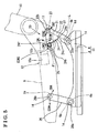
- the seat lifter apparatus 20 includes a pinion gear 25, the first link member 21 serving as a base member and the lower arm 8 serving as a supporting member.
- the pinion gear 25 is fixedly mounted on an end portion of a rotation shaft of a motor device 12 serving as a driving device so as to rotate together with the rotation shaft.
- the lower arm 8 supports a weight (a load) of an occupant seated on the seat cushion 7.
- the motor device 12 is positioned outside the lower arm 8, that is, the motor device 12 is oppositely positioned to the lateral center of the seat cushion 7 relative to the lower arm 8.
- the pinion gear 25, which is fixedly mounted on the rotation shaft of the motor device 12, penetrates the lower arm 8 and protrudes from the lower arm 8 by a predetermined amount toward the lateral center of the seat cushion 7.
- the first link member 21 is positioned closer to the lateral center of the seat cushion 7 relative to the lower arm 8.
- the first link member 21 includes a sector gear 24 having teeth, that is, outer teeth which are arranged in an arc shape and is engaged with the pinion gear 25.
- the motor device 12 to which the pinion 25 is connected, includes a motor portion 12a and a reduction unit 12b.
- a speed of a driving force of the motor portion 12a is reduced by means of a worm gear of the reduction unit 12b and then the driving force is transmitted to the pinion gear 25.
- the worm gear of the motor device 12 includes a self-locking function restricting an input side of the motor device 12 from being rotated by a rotary force outputted by an output side of the motor device 12.
- the pinion gear 25, that is the output side of the motor portion 12a rotates only when the driving force of the motor portion 12a is supplied to the input side.
- the motor device 12 is fixedly attached to an outer flat portion of the lower arm 8 by means of a bolt, that is, the motor device 12 is oppositely positioned to the lateral center of the seat cushion 7 relative to the lower arm 8.
- the pinion gear 25 of the motor device 12 is rotatably supported by a second bearing 28 formed on the lower arm 8 as shown in Fig. 4 .
- the first link member 21 includes a first link portion 22 and the sector gear 24 integrally formed at the first link portion 22.
- the first link portion 22 is formed into a long shape and a pivot hole 22a is formed on one end portion (hereinafter referred to as a first end portion) of the first link portion 22 relative to a lengthwise direction thereof.
- the first link portion 22 is pivotally connected to the attachment hole 6d of the upper rail 6 by means of a pivot shaft 14 inserted into the attachment hole 6d of the upper rail 6 so as to be positioned outside the upper rail 6.
- the first link member 21 is positioned laterally outside of the upper rail 6.
- the first link portion 22 includes a securing hole 22b formed on the other end portion (hereinafter referred to as a second end portion) of the first link portion 22 relative to the lengthwise direction.
- the securing hole 22b is fixedly attached to a drive transmission rod 13 at a vicinity of an end portion of the drive transmission rod 13 so as to rotate together with the drive transmission rod 13.
- the drive transmission rod 13 is rotatably supported by a first bearing 23 formed at a rear portion of the lower arm 8.
- the pair of the lower arms 8, 8 each arranged on left and right sides of the vehicle is connected with each other by means of the drive transmission rod 13.
- the first bearing 23 of the lower arm 8 is positioned rearward and slightly upward relative to the pivot hole 22a of the first link portion 22.
- the sector gear 24 includes the outer teeth arranged in the arc shape whose center corresponds to the securing hole 22b of the first link portion 22, that is, corresponds to the first bearing 23 formed on the lower arm 8 so as to be positioned coaxially with the securing hole 22b.
- the outer teeth arranged in the arc shape face a substantially front direction when the seat lifter apparatus 20 ( Fig. 1 ) is in the fully lowered position.
- the outer teeth of the sector gear 24 engage with the pinion gear 25 at an engagement portion 24a.
- the engagement portion 24a includes six teeth in the embodiments as shown in Figs. 2 and 4 , however, the number of the teeth may be arbitrary determined.
- a tooth that is positioned farthest away from a center line L refers to a tooth 24b.
- a no-teeth portion 24f is formed next to the tooth 24b so as to be positioned away from the center line L. In the no-teeth portion 24f, no engagement occurs between the pinion 25 and the outer teeth of the sector gear 24.
- the no-teeth portion 24f may be formed into any other shape as long as no engagement occurs between the pinion 25 and the outer teeth of the sector gear 24 when the pinion gear 25 comes to the no-teeth portion 24f, and thus the pinion gear 25 stops rotating. Accordingly, as the pinion gear 25 engages with the engagement portion 24a and rotates or moves relative to the sector gear 24 in a direction away from the center line L, a tooth of the pinion gear 25 eventually reaches the no-teeth portion 24f, and thus the rotation of the pinion gear 25 stops. Thus, a relative rotation between the pinion gear 25 and the sector gear 24, that is, an orbital motion of the pinion gear 25 about the first bearing 23 is restricted and stops. Thus, the no-teeth portion 24f serves as a stopper for stopping the seat cushion 7 from moving upward.
- a tooth that is positioned closest to the center line L refers to a tooth 24c.
- the tooth 24c is formed into a similar shape to that of the other teeth of the engagement portion 24a, however, a thickness T of a first tooth root 24d of the tooth 24c is set to be larger than a thickness t of a second tooth root of the other teeth of the engagement portion 24a. This increases a section modulus of the first tooth root 24d of the tooth 24c, thereby improving a strength of the tooth 24c.
- a base portion 24e is formed next to the tooth 24c of the engagement portion 24a so as to be positioned closer to the center line L relative to the tooth 24c.
- the base portion 24e includes a contact portion 27 serving as a restriction mechanism restricting the relative rotation between the pinion gear 25 and the sector gear 24 in a direction in which the pinion gear 25 comes closer to the center line L.
- the contact portion 27 is formed in a vicinity of an intersection of an extended line of an orbital path of a rotation center of the pinion gear 25 and the base portion 24e of the sector gear 24.
- the orbital path of the rotation center of the pinion gear 25 refers to a trajectory created by the rotation center of the pinion gear 25 when the pinion gear 25 moves relative to the sector gear 24, that is, when the pinion gear 25 orbits about the first bearing 23, while engaging with the engagement portion 24a.
- the pinion gear 25 receives from the contact portion 27 a reaction force F2 working substantially in a direction of a tangent line to the orbital path of the rotation center of the pinion gear 25. Consequently, a component force of the reaction force F2, which works in a direction that the first bearing 23 is separated away from the second bearing 28, is small, that is, reduced.
- the contact portion 27 is formed in a manner that a radially outer end of a second tooth 25b serving as a tooth of the pinion gear 25, that is disengaged from the engagement portion 24a, comes in contact with the contact portion 27 when a first tooth 25a of the pinion gear 25 is engaged with the tooth 24c of the engagement portion 24a of the sector gear 24.
- the contact portion 27 includes a protrusion 27a formed so as to extend in a thickness direction of the sector gear 24.
- the protrusion 27a includes on the top thereof a portion R.
- the portion R is formed in a predetermined size so as not to be deformed under an impact force when any tooth of the pinion gear 25 comes in contact with the portion R.
- the lower arm 8 serving as the supporting member is made of a long plate.
- the lower arm 8 is arranged so as to stand in the vertical direction and so as to extend in the front-end direction.
- the lower arm 8 supports the weight (the load) of the occupant via a cushion constituting the seat cushion 7.
- the force applied to the lower arm 8 refers to the weight of the occupant, and a sum of a load of the seat cushion 7 and a load of the seatback 9.
- the pinion gear 25 of the motor device 12 fixedly attached to the lower arm 8 is also pushed downward in the direction of gravity by the weight of the occupant and other loads.
- the securing hole 22b of the first link member 21 is also pushed downward in the direction of gravity by the weight of the occupant and other loads because the first link member 21 is supported by the first bearing 23 of the lower arm 8 via the drive transmission rod 13. Consequently, a rotary force which has a rotation center on the pivot hole 22a and works in a direction CW2 (clockwise direction) is applied to the first link member 21 when the occupant is seated on the seat cushion 7.
- the engagement portion 24a of the sector gear 24 is rotated relative to the pinion gear 25 engaged with the engagement portion 24a in the opposite direction to the direction in which the pinion gear 25 is pushed by the loads (downward in a direction of gravity). Because the pinion gear 25 and the motor portion 12a are connected with each other via the worm gear having the self-locking function, the pinion gear 25 does not rotate in any direction unless the motor portion 12a is driven. At this time, the engagement portion 24a, the teeth of the pinion gear 25 engaged with the engagement portion 24a and the worm gear receive the loads. This restricts the seat cushion 7 from falling down while the pinion gear 25 and the engagement portion 24a of the sector gear 24 are engaged with each other.
- a pivot hole 8a is formed at a front portion of the lower arm 8.
- the first bearing 23 and the second bearing 28 are formed at the rear portion of the lower arm 8 in a manner that the first bearing 23 is positioned rearward by a predetermined distance relative to the second bearing 28.
- the pivot hole 8a, the first bearing 23 and the second bearing 28 are through holes.
- the first bearing 23 is provided with a boss portion formed by a burring process. The boss portion projects so as to assure a contact of the first bearing 23 and the drive transmission rod 13 supported by the first bearing 23, thereby preventing misalignment of a rotational axis of the drive transmission rod 13.
- the lower arm 8 is supported, via the drive transmission rod 13 supported by the first bearing 23 formed on the lower arm 8, at the securing hole 22b formed on the sector gear 24.
- the second link 26 includes rotation holes 26a, 26b formed on both ends of the second link 26 respectively.
- the rotation hole 26a is pivotally connected to the attachment hole 6c of the upper rail 6 and the rotation hole 26b is pivotally connected to the pivot hole 8a of the lower arm 8.
- a four-bar linkage is established among the lower arm 8, the upper rail 6, the first link portion 22 and the second link 26, and thus the lower arm 8 is pivotally mounted on the upper rail 6.
- the upper arm 10 constituting the seatback 9 is mounted on an upper rear portion of the lower arm 8 so as to be pivotable relative to the lower arm 8.
- the tooth face 24g faces upward and the tooth face 25d refers to the tooth face that faces forward relative to a rotation direction of the pinion gear 25 rotating in the direction CW3 (clockwise direction).
- the motor portion 12a is driven and the driving force of the motor portion 12a is transmitted to the pinion gear 25 via the worm gear serving as the reduction unit 12b.
- the pinion gear 25 then rotates about a rotation axis thereof in the direction CW3 (clockwise direction) in Fig. 2 .
- the rotation of the pinion gear 25 causes the tooth face 25d to further push the tooth face 24g that is already engaged with the tooth face 25d.
- the sector gear 24 starts rotating about the first bearing 23 relative to the pinion gear 25 in a direction CCW1 (counterclockwise direction) in Fig. 2 .
- the securing hole 22b formed on the first end portion of the first link portion 22, which is formed integrally with the sector gear 24 and works as the first link member 21 rotates about the pivot hole 22a formed on the second end portion of the first link portion 22 in a direction CCW2 (counterclockwise direction) relative to the pinion gear 25.
- the seat cushion 7 or the lower arm 8
- the motor device 12 including the pinion gear 25 moves upward as the first link member 21 (or the sector gear 24) rotates relative to the pinion gear 25.
- the second link 26 follows an upward movement of the seat cushion 7 (or the lower arm 8) and pivots about the rotation hole 26a in a direction CCW4 (counterclockwise direction) so as to support the front portion of the lower arm 8.
- a driving torque is transmitted via the drive transmission rod 13, thereby operating the lower arm 8, the first link 22, the second link 26 and the like each mounted on the other one of the pair of the upper rails 6, 6, that is, in the embodiments, the upper rail 6 that is arranged on the right side of the vehicle. And thus the seat cushion 7 (or the lower arm 8) moves upward.
- the seat lifter apparatus 20 may be mounted on each of the pair of upper rail 6, 6. In this case, two seat lifter apparatuses 20, 20 may be operated synchronously with each other to perform the upward movement.
- the pinion gear 25 moves relative to the sector gear 24 and passes through the engagement portion 24a, and then the toot of the pinion gear 25 eventually reaches the no-teeth portion 24f.
- the pinion gear 25, which is driven by the rotary force of the motor portion 12a, stops the rotation relative to the sector gear 24 because the no-teeth portion 24f and the pinion gear 25 are not engageable with each other.
- the no-teeth portion 24f serves as the stopper for stopping the seat cushion 7 from moving upward.
- the securing hole 22b formed on the first end portion of the first link portion 22, which is formed integrally with the sector gear 24 and works as the first link member 21, rotates about the pivot hole 22a formed on the second end portion of the first link portion 22 in the direction CW2 (clockwise direction).
- the lower arm 8 (or the seat cushion 7), to which the motor device 12 including the pinion gear 25 is attached pivotally moves downward as the first link member 21 (or the sector gear 24) and the pinion gear 25 relatively rotate.
- the second link 26 follows a downward movement of the lower arm 8 and pivots about the rotation hole 26a in the direction CW4 (clockwise direction) so as to support the front portion of the lower arm 8.
- the tooth face 25d of the pinion gear 25 engages with the tooth face 24g of the tooth 24c of the engagement portion 24a of the sector gear 24, and thus the pinion gear 25 further moves relative to the sector gear 24 in a direction in which the pinion gear 25 moves closer to the center line L. Then, the radially outer end of the second tooth 25b positioned next to the first tooth 25a comes in contact with the portion R of the protrusion 27a of the contact portion 27.
- the second tooth 25b refers to the tooth positioned behind the first tooth 25a, which is one of the teeth of the pinion gear 25 and which is engaging with the tooth 24c of the sector gear 24, by one tooth relative to the rotation direction of the pinion gear 25. Accordingly, the pinion gear 25 stops rotating about the first bearing 23 relative to the sector gear 24 while being engaged with the engagement portion 24a, that is, the pinion gear 25 stops its orbital motion.
- the contact portion 27 serves as a stopper for stopping the seat cushion 7 from moving downward. At this time when the pinion gear 25 comes in contact with the protrusion 27a of the contact portion 27, the weight of the occupant seated on the seat cushion 7 and other loads act downward, and thus a large load including the weight of the occupant acts on the contact portion 27. As a result, the reaction force F2 from the contact portion 27, which is large in magnitude, acts on the pinion gear 25.
- the reaction force F2 applied from the contact portion 27 to the pinion gear 25 is positioned on the substantial tangent line of the orbital path of the rotation center of the pinion gear 25 because the contact portion 27 is formed in the vicinity of the intersection of the extended line of the path of the rotation center of the pinion gear 25 when the pinion gear 25 orbits about the first bearing 23 and moves relative to the sector gear 24.
- the reaction force F2 works in the direction substantially perpendicular to the direction in which the first bearing 23 is separated away from the second bearing 28. Consequently, the first bearing 23 or the second bearing 28 is restricted from being worn out by the reaction force F2 because the reaction force F2 does not work in the direction in which the first bearing 23 is separated away from the second bearing 28.
- the gear clatter is restricted.
- a tooth face 25e of the first tooth 25a of the pinion gear 25 is in contact with and pushes the tooth face 24h of the tooth 24c of the sector gear 24 in response to the driving force of the motor portion 12a.
- This generates a reaction force F3 that works in a substantially opposite direction to a direction in which the pinion gear 25 pushes the tooth 24c of the sector gear 24 while engaging with the sector gear 24 and moving relative to the sector gear 24.
- the reaction force F2 which the pinion gear 25 receives from the contact portion 27, is cancelled out by the reaction force F3 because the direction of the reaction force F3 is substantially opposite to that of the reaction force F2.
- the reaction force F2 is small, that is, reduced in magnitude and the first bearing 23 or the second bearing 28 is restricted from being worn out by the reaction force F2.
- the sector gear 24 is made so that the thickness T of the first tooth root 24d of the tooth 24c is larger than the thickness t of the second tooth root of the other teeth of the sector gear 24, and thus a section modulus of the first tooth root 24d is large. Therefore, even though the tooth of the pinion gear 25 repetitively pushes the tooth 24c of the sector gear 24 in one direction and in the other direction when the teeth of the pinion gear 25 are moving relative to the sector gear 24 and when the pinion gear 25 comes to stop, a stress applied to the tooth 24c is alleviated and the tooth 24c is restricted from being damaged.
- the contact portion 27 is formed at the sector gear 24 so that the pinion gear 25 stops moving upon coming in contact with the contact portion 27 relative to the sector gear 24 while engaging with the teeth of the sector gear 24.
- the contact portion 27 is formed at other portion than the engagement portion 24a engaging with the pinion gear 25 so that the reaction force F2, which acts from the sector gear 24 on the pinion gear 25 when the pinion gear 25 stops, does not work as a large force acting in the direction in which the first bearing 23 is separated away from the second bearing 28. Accordingly, the second bearing 28 supporting the pinion gear 25 is not strongly pushed in the direction in which the second bearing 28 is separated away from the first bearing 23 when the pinion gear 25 stops. As a result, the pinion gear 25, the second bearing 28 or the first bearing 23 is restricted from being worn out.
- the first tooth root 24d of the tooth 24c of the sector gear 24 engaging with the pinion gear 25 receives the rotary force of the pinion gear 25 driven and rotated by the motor device 12.
- the thickness T of the first tooth root 24d of the tooth 24c is set to be larger than the thickness t of the second tooth root of the other teeth of the engagement portion 24a, which increases the section modulus of the first tooth root 24d of the tooth 24c. Therefore, the stress applied to the first tooth root 24d is alleviated even though the tooth 24c receives the pushing force from the pinion gear 25 due to the weight of the occupant supported by the lower arm 8 when the pinion gear 25 rotates while engaging with the sector gear 24.
- the stress applied to the first tooth root 24d is also alleviated even though the tooth 24c receives from the pinion gear 25 a pushing force that acts in a substantially opposite direction to a direction in which the above-mentioned pushing force and that is generated by the rotation of the pinion gear 25 when the pinion gear 25 comes in contact with the contact portion 27 and stops.
- durability and reliability of the sector gear 24 is improved even though the above-described pushing forces are applied alternatively and repetitively.
- the pinion gear 25 receives the reaction force F2 from the teeth of the sector gear 24.
- a direction of the reaction force F3 is substantially opposite to the direction in which the reaction force F2 acting on the pinion gear 25 at the contact portion 27.
- the contact portion 27 is formed in a vicinity of the extended line of the orbital path of the rotation center of the pinion gear 25 when the pinion gear 25 moves relative to the sector gear 24, that is, when the pinion gear 25 orbits about the first bearing 23.
- the direction of the reaction force F2 that the pinion gear 25 receives from the sector gear 24 at the contact portion 27 refers to the direction of the tangent line to the orbital path of the rotation center of the pinion gear 25.
- the direction of the reaction force F2 is substantially perpendicular to the direction in which the first bearing 23 is separated away from the second bearing 28. Consequently, no large pushing force in the direction in which the second bearing 28 and the first bearing 23 are separated away from each other acts on the second bearing 28, and thus the pinion gear 25, the second bearing 28 or the first bearing 23 is restricted from being worn out.
- the sector gear 24 is provided with the contact portion 27 serving as the restriction mechanism for restricting the relative rotation between the pinion gear 25 and the sector gear 24 in a direction in which the pinion gear 25 and the sector gear 24 rotate relative to each other due to the load supported by the lower arm 8.
- the contact portion 27 receives the impact force securely, thereby improving the reliability of the sector gear 24.
- the first and the second embodiments are identical except for a shape of the contact portion, therefore, only the difference will be explained hereunder and the explanation on the identical structures or portions will be omitted.
- the identical numerical designations are given to the parts, the portions and the like having identical functions to those of the first embodiment.
- a contact portion 37 is formed by adding a material to the base portion 24e of the sector gear 24 so as to come in contact with the tooth of the pinion gear 25.
- the contact portion 37 is positioned substantially opposite to the engagement portion 24a where the pinion gear 25 and the sector gear 24 engage with each other and to the first bearing 23 with respect to a center of the second bearing 28 (refer to Figs. 1 and 2 ).
- the contact portion 37 is formed into a shape that matches a shape of the tooth face 25e of a tooth 25c positioned behind the first tooth 25a by two teeth relative to the rotation direction of the pinion gear 25 when the pinion gear 25 rotates about the rotation axis thereof in a direction CCW3 (counterclockwise direction) in Fig. 6 and when the first tooth 25a of the pinion gear 25 engages with the tooth 24c of the sector gear 24 so that the contact portion 37 comes in contact with the tooth face 25e of the tooth 25c.
- the tooth face 25e refers to a tooth face facing forward relative to the rotation direction of the pinion gear 25 rotating in the direction CCW3 (counterclockwise direction).
- a reaction force F4 from the contact surface 37a acts on the pinion gear 25 as shown Fig. 6 .
- the reaction force F4 includes a function for receiving the rotary force of the pinion gear 25, which will be explained later. Accordingly, a magnitude of the reaction force F4 corresponds to a magnitude of a resultant force of a force for stopping the orbital motion of the pinion gear 25 and a force receiving the rotary force of the pinion gear 25.
- the direction of the reaction force F4 is substantially perpendicular to, or alternatively, is opposite to the direction in which the second bearing 28 is separated away from the first bearing 23. That is, the reaction force F4 includes a component force whose direction is substantially perpendicular to, or alternatively, is opposite to the direction in which the second bearing 28 is separated away from the first bearing 23.
- the tooth 24c of the sector gear 24, which is in contact with the first tooth 25a of the pinion gear 25, receives the rotary force of the pinion gear 25 in response to the driving force of the motor portion 12a.
- This generates a reaction force F5 as shown in Fig. 6 .
- a magnitude of the reaction force F5 is small because substantially a half of the reaction force F5 is borne at the contact portion 37 as explained above.
- the reaction force F5 works in a substantially opposite direction to the direction in which the reaction force F4, which is applied from the contact portion 37 of the sector gear 24 to the pinion gear 25, works.
- a component force of the reaction force F5, in the direction in which the second bearing 28 supporting the pinion gear 25 is separated away from the first bearing 23, is small.
- a direction of the component force of the reaction force F5 is opposite to the direction in which the second bearing 28 is separated away from the first bearing 23.
- the two reaction forces F4 and F5 are cancelled out by each other by a certain magnitude. As a result, no large pushing force acts on the pinion gear 25, the second bearing 28 or the first bearing 23, and thus the pinion gear 25, the first bearing 23 or the second bearing 28 is restricted from being worn out.
- the sector gear 24, which causes the reaction force F5 to occur is made so that the thickness T of the first tooth root 24d of the tooth 24c is larger than the thickness t of the second tooth root of the other teeth of the sector gear 24, and thus the section modulus of the first tooth root 24d is large. Therefore, even though the tooth of the pinion gear 25 repetitively pushes the tooth 24c of the sector gear 24 in one direction and in the other direction when the teeth of the pinion gear 25 are moving relative to the sector gear 24 and when the pinion gear 25 comes to stop, the stress applied to the first tooth root 24d of the tooth 24c is alleviated and the tooth 24c is restricted from being damaged. Consequently, in the second embodiment, a similar effect to that of the first embodiment is expected.
- the contact portion 37 in which the tooth of the pinion gear 25 comes in contract with the sector gear 24, is formed to be positioned substantially opposite to the engagement portion 24a where the pinion gear 25 and the sector gear 24 engage with each other and to the first bearing 23 with respect to the center of the second bearing 28.
- the magnitude of the reaction force F4 which the pinion gear 25 in the contact portion 37 receives from the sector gear 24, includes a magnitude of the reaction force generated for stopping the orbital motion of the pinion gear 25, and a magnitude of the reaction force having a substantially same magnitude but working in a substantially opposite direction relative to the reaction force that the pinion gear 25 receives from the engagement portion 24a due to the rotary force of the pinion gear 25.
- reaction force F5 that the pinion gear 25 receives from the tooth 24c of the engagement portion 24a is cancelled out by the reaction force F4 generated at the contact portion 37. Consequently, only the reaction force F4 generated for stopping the orbital motion of the pinion gear 25 acts to the contact portion 37.
- the reaction force F4 works in the direction substantially perpendicular to the direction in which the second bearing 28 supporting the pinion gear 25 is separated away from the first bearing 23. As a result, the pinion gear 25, the second bearing 28 or the first bearing 23 is restricted from being worn out.
- the contact portion 27, 37 corresponding to the restriction mechanism is provided only at an opposite side of the no-teeth portion 24f relative to the engagement portion 24a, so that the contact portion 27, 37 serves as the stopper when the seat cushion 7 is moved downward.
- the contact portion 27, 37 according to the first and the second embodiments may be provided to be positioned outside the tooth 24b of the sector gear 24, that is, as a replacement for the no-teeth portion 24f.
- the seat adjusting apparatus 20 is used in an apparatus for adjusting the height of the seat cushion 7 of the seat for the vehicle.
- the seat adjusting apparatus 20 according to this disclosure may be used in a tilt apparatus for adjusting an angle of a seating surface of the seat cushion by means of an engagement between the pinion gear 25 and the sector gear 24.
- the seat adjusting apparatus 20 according to this disclosure may also be used in an angle adjusting apparatus for adjusting an angle of a seatback relative to the seat cushion of the seat for the vehicle by means of the engagement between the pinion gear 25 and the sector gear 24.
- the first link portion 22 and the sector gear 24 are integrally formed.
- the sector gear 24 engages with the pinion gear 25 mounted on the motor device 12 that is attached to the lower arm 8, thereby causing the seat cushion 7 to move upward and downward.
- the sector gear 24 may be provided at the lower arm 8 and the motor device 12 including the pinion gear 25 may be fixedly attached to the first link portion 22, so that the pinion gear 25 and the sector gear 24 engage with each other, and thus the seat cushion 7 is moved upward and downward.
- the contact portion 27, 37 serving as the restriction mechanism may be provided at the sector gear 24 in this case, which will have the similar effects to those according to the first and the second embodiments.
- the seat adjusting apparatus 20 may be used in an adjusting apparatus adjusting the height or the angle by means of the engagement between the pinion gear 25 and the sector gear 24, which is manually operated instead of driven by the motor device 12.
- the driving force of the motor does not work, therefore, an impact due to the weight of the occupant is alleviated and thus the durability improves accordingly.
- a seat adjusting apparatus (20) for a vehicle includes a supporting member (8) pivotally supported at a base member (21) by means of a first bearing (23), a pinion gear (25) driven by a driving device (12), a sector gear (24) engageable with the pinion gear and a restriction mechanism (27, 37) formed at the sector gear for restricting a relative rotation between the pinion gear and the sector gear.
- the restriction mechanism includes a contact portion (27, 37) coming in contact with the pinion gear so that a component force of a reaction force (F2, F4), which works in a direction in which the first bearing is separated from the second bearing (28), acting on the pinion gear is reduced.
- a thickness (T) of a first tooth root (24d) of a tooth (24c) included in the teeth formed at the sector gear is larger than a thickness (t) of a second tooth root of the other teeth formed at the sector gear.
Description
- This disclosure relates to a seat adjusting apparatus for a vehicle, which provides a dimensional adjustment by moving movable portions of the seat for the vehicle.
- A seat lifter apparatus is usually provided to a seat for a vehicle in order to adjust a height of the seat according to a physical attribute or preference of a seat occupant. A known seat lifter apparatus disclosed in
JP2009-154638A - A lifter mechanism disclosed in
JP2006-282019A - According to the seat lifter apparatus disclosed in
JP2009-154638A - As with the seat lifter apparatus disclosed in
JP2009-154638A JP2006-282019A JP2009-154638A - A need thus exists for a seat adjusting apparatus for a vehicle, which is small in size and provides a high reliability.
- According to an aspect of this disclosure, a seat adjusting apparatus for a vehicle includes a base member adapted to be provided at a vehicle floor, a supporting member pivotally supported at the base member by means of a first bearing for supporting a load applied to the supporting member, a pinion gear rotatably supported at either one of the base member and the supporting member by means of a second bearing, and driven and rotated by a driving device having a self-locking function, a sector gear integrally provided at the other one of the base member and the supporting member so as to be coaxial with the first bearing and formed with teeth engageable with the pinion gear at an engagement portion, and a restriction mechanism for restricting a relative rotation in at least one direction between the pinion gear and the sector gear. The restriction mechanism is formed at the sector gear and includes a contact portion which comes in contact with the pinion gear in other portion than the engagement portion so that a component force, which works in a direction in which the first bearing is separated away from the second bearing, of a reaction force acting on the pinion gear is reduced. A thickness of a first tooth root of a tooth, which is included in the teeth formed at the sector gear and engages with the pinion gear when the restriction mechanism is in contact with the pinion gear, is larger than a thickness of a second tooth root of the other teeth formed at the sector gear.
- Due to the above-described structure, the restriction mechanism is formed at the sector gear so that the pinion gear stops moving upon coming in contact with the restriction mechanism relative to the sector gear while engaging with the teeth of the sector gear. The restriction mechanism is formed at other portion than the engagement portion engaging with the pinion gear so that a reaction force, which acts from the sector gear on the pinion gear when the pinion gear stops, does not work as a large force acting in the direction in which the first bearing is separated away from the second bearing. Accordingly, the second bearing supporting the pinion gear is not strongly pushed in the direction in which the second bearing is separated away from the first bearing when the pinion gear stops. As a result, the pinion gear, the second bearing or the first bearing is restricted from being worn out.
- In addition, when the pinion gear comes in contact with the restriction mechanism and stops, the first tooth root of the tooth of the sector gear engaging with the pinion gear receives a rotary force of the pinion gear driven and rotated by the driving device. However, the thickness of the first tooth root of the tooth is set to be larger than the thickness of the second tooth root of the other teeth of the engagement portion, which increases a section modulus of the first tooth root of the tooth. Therefore, the stress applied to the first tooth root is alleviated even though the tooth receives a pushing force from the pinion gear due to the load supported by the supporting member while the pinion gear is rotating. In addition, the stress applied to the first tooth root is also alleviated even though the tooth receives from the pinion gear a pushing force that acts in a substantially opposite direction to a direction in which the above-mentioned pushing force and that is generated by the rotation of the pinion gear when the pinion gear comes in contact with the restriction mechanism and stops. Thus, a reliability of the sector gear is improved even though the above-described pushing forces are applied alternatively and repetitively. Further, when the pinion gear comes in contact with the restriction mechanism and stops, the pinion gear receives the reaction force from the teeth of the sector gear. A direction of the reaction force is substantially opposite to the direction in which the reaction force acting on the pinion gear at the restriction mechanism. Therefore, the reaction force at the restriction mechanism is cancelled out, which prevents the second bearing supporting the pinion gear from being strongly pushed in the direction in which the second bearing is separated away from the second bearing when the pinion gear stops. As a result, the pinion gear, the second bearing or the first bearing is restricted from being worn out.
- According to another aspect of this disclosure, the contact portion comes in contact with the pinion gear in a vicinity of an orbital path of a rotation center of the pinion gear when the pinion gear orbits about the sector gear.
- In order to stop the pinion gear, the contact portion is formed in a vicinity of an extended line of the orbital path of the rotation center of the pinion gear when the pinion gear moves relative to the sector gear, that is, when the pinion gear orbits about the first bearing. Accordingly, the direction of the reaction force that the pinion gear receives from the sector gear at the contact portion refers to a direction of a tangent line to the orbital path of the rotation center of the pinion gear. In other words, the direction of the reaction force is substantially perpendicular to the direction in which the first bearing is separated away from the second bearing. Consequently, no large pushing force in the direction in which the second bearing and the first bearing are separated away from each other acts on the second bearing, and thus the pinion gear, the second bearing or the first bearing is restricted from being worn out.
- According to a further aspect of this disclosure, the contact portion comes in contact with the pinion gear at an opposite side, with respect to a center of the second bearing, to a side at which the engagement portion and the first bearing are positioned.
- The contact portion, in which the tooth of the pinion gear comes in contract with the sector gear, is formed to be positioned substantially opposite to the engagement portion, where the pinion gear and the sector gear engage with each other, and to the first bearing with respect to the center of the second bearing. Thus, a magnitude of the reaction force, which the pinion gear in the contact portion receives from the sector gear, includes a magnitude of the reaction force generated for stopping the orbital motion of the pinion gear, and a magnitude of the reaction force having a substantially same magnitude but working in a substantially opposite direction relative to the reaction force that the pinion gear receives from the engagement portion. Thus, the reaction force that the pinion gear receives from the tooth of the engagement portion is cancelled out by the reaction force generated at the contact portion. Consequently, only the reaction force generated for stopping the orbital motion of the pinion gear acts to the contact portion. The reaction force works in the direction substantially perpendicular to the direction in which the second bearing supporting the pinion gear is separated away from the first bearing. As a result, the pinion gear, the second bearing or the first bearing is restricted from being worn out.
- According to a further aspect of this disclosure, the restriction mechanism restricts the relative rotation between the pinion gear and the sector gear in a direction in which the relative rotation is caused by the load applied to the supporting member.
- The sector gear is provided with the restriction mechanism for restricting the relative rotation between the pinion gear and the sector gear in the direction in which the pinion gear and the sector gear rotate relative to each other due to the load supported by the supporting member. In case that the direction in which the pinion gear is pushed by the load and the direction in which the sector gear moves relative to the pinion gear when the sector gear is pushed by the load supported by the supporting member are relatively opposite to each other, when the pinion gear comes in contact with the sector gear and stops, an impact force is applied to the sector. The impact force includes the rotary force of the pinion gear and the load supported by the supporting member, and is large in magnitude. However, the restriction mechanism receives the impact force securely, thereby improving the reliability of the sector gear.
- According to a further aspect of this disclosure, the base member refers to a link member. One end portion of the base member is pivotally supported by an upper rail of a seat track adapted to be mounted on the vehicle floor for adjusting, in a front-rear direction of the vehicle, a seat cushion on which an occupant is seated and the other end portion of the base member is pivotally supported by the supporting member constituting the seat cushion. The supporting member refers to the lower arm. The pinion gear is rotatably supported by the second bearing formed on the supporting member.
- The base member refers to the link member whose end portions are pivotally supported by the upper rail of the seat track adapted to be mounted on the vehicle floor and by the supporting member constituting the seat cushion that supports the weight of the occupant, respectively. The supporting member refers to the lower arm. The pinion gear is rotatably supported by the second bearing formed on the supporting member. The sector gear is integrally provided at the base member so as to be coaxial with the first bearing. Thus, the seat adjusting apparatus for the vehicle according to this disclosure is used for moving the seat cushion upward and downward, which the occupant is seated on and the large load is applied to. Due to the above described structure, when the seat cushion is moved downward and then stopped, the tooth of the pinion gear comes in contact with the restriction mechanism and receives the load securely. At this time, the direction of the reaction force generated at the restriction mechanism and acting on the pinion gear, and the direction of the reaction force generated at the engagement portion, which receives the rotary force of the pinion gear, and acting on the pinion gear are substantially opposite to each other. Consequently, the two reaction forces are cancelled out by each other by a certain magnitude. A remaining reaction force after the cancellation works in the direction substantially perpendicular to the direction in which the first bearing is separated away from the second bearing. Consequently, the component force of the reaction force, which works in the direction that the first bearing is separated away from the second bearing, is small, that is, reduced. As a result, the seat adjusting apparatus for the vehicle, where the pinion gear, the second bearing or the first bearing is restricted from being worn out, is provided.
- According to a further aspect of this disclosure, the base member is provided with a pivot hole formed on a first end portion of the base member and a securing hole formed on a second end portion of the base member for supporting the first bearing. The base member includes a first link portion formed into a long shape and is pivotally connected to an attachment hole of the upper rail by means of a pivot shaft so as to be positioned outside of the upper rail and the sector gear integrally formed at the first link portion.
- Consequently, the seat adjusting apparatus for the vehicle, which is small in size and which includes less number of parts, is provided.
- According to a further aspect of this disclosure, a no-teeth portion for restricting an engagement with the pinion gear is formed at the sector gear so as to be positioned next to a tooth and so as to be positioned away from a center line. The center line connects a center of the pivot hole formed on the base member and a center of the securing hole formed on the first link. The tooth is included in the teeth of the sector gear and is positioned farthest away from the center line.
- The rotation of the pinion gear stops when the tooth of the pinion gear reaches the no-teeth portion. This stops the relative rotation between the pinion gear and the sector gear. Thus, the no-teeth portion serves as a stopper for stopping the supporting member from moving upward.
- According to a further aspect of this disclosure, the contact portion includes a protrusion coming in contact with a radially outer end of a tooth of the pinion gear under a condition that the pinion gear engages with the engagement portion of the sector gear. The tooth of the pinion gear is disengaged from the engagement portion of the sector gear.
- The pinion gear stops moving relative to the sector gear while being engaged with the engagement portion of the sector gear, that is, the pinion gear stops its orbital motion. Thus, the contact portion serves as a stopper for stopping the supporting member from moving downward.
- The foregoing and additional features and characteristics of this disclosure will become more apparent from the following detailed description considered with the reference to the accompanying drawings, wherein:
-
Fig. 1 is a schematic side view of a seat apparatus for a vehicle according to first and second embodiments disclosed here; -
Fig. 2 is a perspective side view of a seat adjusting apparatus for a vehicle according to the first and the second embodiments disclosed here when a seat cushion is stationarily in a lowered position; -
Fig. 3 is an enlarged view of a contact portion formed at a sector gear of the seat adjusting apparatus for the vehicle according to the first embodiment; -
Fig. 4 is an exploded perspective view of the seat adjusting apparatus for the vehicle according to the first embodiment; -
Fig. 5 is a perspective side view of the seat adjusting apparatus for the vehicle according to the first and the second embodiments disclosed here when the seat cushion is stationarily in a raised position; and -
Fig. 6 is an enlarged view of a contact portion formed at the sector gear of the seat adjusting apparatus for the vehicle according to the second embodiment disclosed here. - A first embodiment of a
seat lifter apparatus 20 according to this disclosure will be explained. InFig. 1 , theseat lifter apparatus 20, which serves as a seat adjusting apparatus for a vehicle (hereinafter referred to as the seat adjusting apparatus) for adjusting a height of a seat cushion on which a vehicle occupant is seated, is mounted on aseat apparatus 2 for a vehicle. InFig. 2 , the seat cushion is stationarily in a fully lowered position. As used herein, the terms "a front-rear direction", "a lateral direction" and "a vertical direction (an up-down direction)" and derivatives thereof refer to the directions relative to the vehicle. - As shown in
Fig. 1 , theseat apparatus 2 for the vehicle (hereinafter referred to as the seat apparatus 2) includes aseat track 11 including alower rail 4 and anupper rail 6, theseat lifter apparatus 20, alower arm 8 constituting a seat cushion 7 and a part of theseat lifter apparatus 20, and anupper arm 10 constituting aseatback 9. - According to the
seat apparatus 2 of the first embodiment, as shown inFig. 1 , a pair oflower rails vehicle floor 1 by means ofbrackets lower rails upper rail 6, which allows the seat cushion 7 to move in the front-rear direction relative to thelower rail 4, is slidably mounted on eachlower rail 4. InFig. 1 , one of the pair of seat tracks 11, 11 and one of thebrackets lower rail 4 and theupper rail 6 are structured in a manner that a sliding motion of theupper rail 6 relative to thelower rail 4 is alternately locked and unlocked by means of a locking-and-unlocking mechanism. - As shown in
Figs. 1 and2 , alink attachment portion 6a is integrally formed on an upper front end portion of theupper rail 6, and alink attachment portion 6b is integrally formed on an upper rear end portion of theupper rail 6. Thelink attachment portions link attachment portion 6a is provided with anattachment hole 6c, and thelink attachment portion 6b is provided with anattachment hole 6d. Afirst link member 21 serving as a link member of theseat lifter apparatus 20 is pivotally connected to thelink attachment portion 6b and asecond link 26 of theseat lifter apparatus 20 is pivotally connected to thelink attachment portion 6a. Thus, theseat lifter apparatus 20 is pivotally connected to theupper rail 6 via thelink attachment portions first link member 21 and thesecond link 26. One end portion of thefirst link member 21 is pivotally supported by theupper rail 6, and the other end portion of thefirst link member 21 is pivotally supported by thelower arm 8. - The
seat lifter apparatus 20 according to the first and the second embodiments of this disclosure will be explained with reference toFigs. 1 ,2 and4 . Theseat lifter apparatus 20 is mounted on either one of the pair ofupper rails seat lifter apparatus 20 is mounted on theupper rail 6 arranged on the left side of the vehicle. Theseat lifter apparatus 20 includes apinion gear 25, thefirst link member 21 serving as a base member and thelower arm 8 serving as a supporting member. Thepinion gear 25 is fixedly mounted on an end portion of a rotation shaft of amotor device 12 serving as a driving device so as to rotate together with the rotation shaft. Thelower arm 8 supports a weight (a load) of an occupant seated on the seat cushion 7. - The
motor device 12 is positioned outside thelower arm 8, that is, themotor device 12 is oppositely positioned to the lateral center of the seat cushion 7 relative to thelower arm 8. Thepinion gear 25, which is fixedly mounted on the rotation shaft of themotor device 12, penetrates thelower arm 8 and protrudes from thelower arm 8 by a predetermined amount toward the lateral center of the seat cushion 7. Thefirst link member 21 is positioned closer to the lateral center of the seat cushion 7 relative to thelower arm 8. Thefirst link member 21 includes asector gear 24 having teeth, that is, outer teeth which are arranged in an arc shape and is engaged with thepinion gear 25. - As shown in
Figs. 1 ,2 , and4 , themotor device 12, to which thepinion 25 is connected, includes amotor portion 12a and areduction unit 12b. A speed of a driving force of themotor portion 12a is reduced by means of a worm gear of thereduction unit 12b and then the driving force is transmitted to thepinion gear 25. The worm gear of themotor device 12 includes a self-locking function restricting an input side of themotor device 12 from being rotated by a rotary force outputted by an output side of themotor device 12. Thus, thepinion gear 25, that is the output side of themotor portion 12a, rotates only when the driving force of themotor portion 12a is supplied to the input side. - The
motor device 12 is fixedly attached to an outer flat portion of thelower arm 8 by means of a bolt, that is, themotor device 12 is oppositely positioned to the lateral center of the seat cushion 7 relative to thelower arm 8. Thepinion gear 25 of themotor device 12 is rotatably supported by asecond bearing 28 formed on thelower arm 8 as shown inFig. 4 . - As shown in
Figs. 2 and4 , thefirst link member 21 includes afirst link portion 22 and thesector gear 24 integrally formed at thefirst link portion 22. Thefirst link portion 22 is formed into a long shape and apivot hole 22a is formed on one end portion (hereinafter referred to as a first end portion) of thefirst link portion 22 relative to a lengthwise direction thereof. Thefirst link portion 22 is pivotally connected to theattachment hole 6d of theupper rail 6 by means of apivot shaft 14 inserted into theattachment hole 6d of theupper rail 6 so as to be positioned outside theupper rail 6. Thus, thefirst link member 21 is positioned laterally outside of theupper rail 6. Thefirst link portion 22 includes a securinghole 22b formed on the other end portion (hereinafter referred to as a second end portion) of thefirst link portion 22 relative to the lengthwise direction. The securinghole 22b is fixedly attached to adrive transmission rod 13 at a vicinity of an end portion of thedrive transmission rod 13 so as to rotate together with thedrive transmission rod 13. Thedrive transmission rod 13 is rotatably supported by afirst bearing 23 formed at a rear portion of thelower arm 8. Thus, the pair of thelower arms drive transmission rod 13. When the seat lifter apparatus 20 (Figs. 1 and2 ) is in the fully lowered position, thefirst bearing 23 of thelower arm 8 is positioned rearward and slightly upward relative to thepivot hole 22a of thefirst link portion 22. - As shown in
Figs. 2 and4 , thesector gear 24 includes the outer teeth arranged in the arc shape whose center corresponds to the securinghole 22b of thefirst link portion 22, that is, corresponds to thefirst bearing 23 formed on thelower arm 8 so as to be positioned coaxially with the securinghole 22b. In the first embodiment, the outer teeth arranged in the arc shape face a substantially front direction when the seat lifter apparatus 20 (Fig. 1 ) is in the fully lowered position. The outer teeth of thesector gear 24 engage with thepinion gear 25 at anengagement portion 24a. Theengagement portion 24a includes six teeth in the embodiments as shown inFigs. 2 and4 , however, the number of the teeth may be arbitrary determined. - Among the six teeth of the
engagement portion 24a of thesector gear 24, a tooth that is positioned farthest away from a center line L (a line connecting a center of thepivot hole 22a and a center of the securinghole 22b each formed on the first link portion 22) refers to atooth 24b. A no-teeth portion 24f is formed next to thetooth 24b so as to be positioned away from the center line L. In the no-teeth portion 24f, no engagement occurs between thepinion 25 and the outer teeth of thesector gear 24. The no-teeth portion 24f may be formed into any other shape as long as no engagement occurs between thepinion 25 and the outer teeth of thesector gear 24 when thepinion gear 25 comes to the no-teeth portion 24f, and thus thepinion gear 25 stops rotating. Accordingly, as thepinion gear 25 engages with theengagement portion 24a and rotates or moves relative to thesector gear 24 in a direction away from the center line L, a tooth of thepinion gear 25 eventually reaches the no-teeth portion 24f, and thus the rotation of thepinion gear 25 stops. Thus, a relative rotation between thepinion gear 25 and thesector gear 24, that is, an orbital motion of thepinion gear 25 about thefirst bearing 23 is restricted and stops. Thus, the no-teeth portion 24f serves as a stopper for stopping the seat cushion 7 from moving upward. - As shown in
Figs. 2 and3 , among the six teeth of theengagement portion 24a, a tooth that is positioned closest to the center line L, refers to atooth 24c. Thetooth 24c is formed into a similar shape to that of the other teeth of theengagement portion 24a, however, a thickness T of afirst tooth root 24d of thetooth 24c is set to be larger than a thickness t of a second tooth root of the other teeth of theengagement portion 24a. This increases a section modulus of thefirst tooth root 24d of thetooth 24c, thereby improving a strength of thetooth 24c. - As shown in
Figs. 2 and3 , abase portion 24e is formed next to thetooth 24c of theengagement portion 24a so as to be positioned closer to the center line L relative to thetooth 24c. Thebase portion 24e includes acontact portion 27 serving as a restriction mechanism restricting the relative rotation between thepinion gear 25 and thesector gear 24 in a direction in which thepinion gear 25 comes closer to the center line L. Thecontact portion 27 is formed in a vicinity of an intersection of an extended line of an orbital path of a rotation center of thepinion gear 25 and thebase portion 24e of thesector gear 24. The orbital path of the rotation center of thepinion gear 25 refers to a trajectory created by the rotation center of thepinion gear 25 when thepinion gear 25 moves relative to thesector gear 24, that is, when thepinion gear 25 orbits about thefirst bearing 23, while engaging with theengagement portion 24a. After thepinion gear 25 moves relative to thesector gear 24, and when any tooth of thepinion gear 25 comes in contact with thecontact portion 27, thepinion gear 25 receives from thecontact portion 27 a reaction force F2 working substantially in a direction of a tangent line to the orbital path of the rotation center of thepinion gear 25. Consequently, a component force of the reaction force F2, which works in a direction that thefirst bearing 23 is separated away from thesecond bearing 28, is small, that is, reduced. - The
contact portion 27 is formed in a manner that a radially outer end of asecond tooth 25b serving as a tooth of thepinion gear 25, that is disengaged from theengagement portion 24a, comes in contact with thecontact portion 27 when afirst tooth 25a of thepinion gear 25 is engaged with thetooth 24c of theengagement portion 24a of thesector gear 24. Thecontact portion 27 includes aprotrusion 27a formed so as to extend in a thickness direction of thesector gear 24. Theprotrusion 27a includes on the top thereof a portion R. The portion R is formed in a predetermined size so as not to be deformed under an impact force when any tooth of thepinion gear 25 comes in contact with the portion R. - As shown in
Figs. 1 and2 , thelower arm 8 serving as the supporting member is made of a long plate. Thelower arm 8 is arranged so as to stand in the vertical direction and so as to extend in the front-end direction. Thelower arm 8 supports the weight (the load) of the occupant via a cushion constituting the seat cushion 7. Thus, when the occupant is seated on the seat cushion 7, a force working downward in a direction of gravity is applied to thelower arm 8. The force applied to thelower arm 8 refers to the weight of the occupant, and a sum of a load of the seat cushion 7 and a load of theseatback 9. In other words, thepinion gear 25 of themotor device 12 fixedly attached to thelower arm 8 is also pushed downward in the direction of gravity by the weight of the occupant and other loads. In addition, the securinghole 22b of thefirst link member 21 is also pushed downward in the direction of gravity by the weight of the occupant and other loads because thefirst link member 21 is supported by thefirst bearing 23 of thelower arm 8 via thedrive transmission rod 13. Consequently, a rotary force which has a rotation center on thepivot hole 22a and works in a direction CW2 (clockwise direction) is applied to thefirst link member 21 when the occupant is seated on the seat cushion 7. At this time, theengagement portion 24a of thesector gear 24 is rotated relative to thepinion gear 25 engaged with theengagement portion 24a in the opposite direction to the direction in which thepinion gear 25 is pushed by the loads (downward in a direction of gravity). Because thepinion gear 25 and themotor portion 12a are connected with each other via the worm gear having the self-locking function, thepinion gear 25 does not rotate in any direction unless themotor portion 12a is driven. At this time, theengagement portion 24a, the teeth of thepinion gear 25 engaged with theengagement portion 24a and the worm gear receive the loads. This restricts the seat cushion 7 from falling down while thepinion gear 25 and theengagement portion 24a of thesector gear 24 are engaged with each other. - A
pivot hole 8a is formed at a front portion of thelower arm 8. As shown inFig. 4 , thefirst bearing 23 and thesecond bearing 28 are formed at the rear portion of thelower arm 8 in a manner that thefirst bearing 23 is positioned rearward by a predetermined distance relative to thesecond bearing 28. Thepivot hole 8a, thefirst bearing 23 and thesecond bearing 28 are through holes. Thefirst bearing 23 is provided with a boss portion formed by a burring process. The boss portion projects so as to assure a contact of thefirst bearing 23 and thedrive transmission rod 13 supported by thefirst bearing 23, thereby preventing misalignment of a rotational axis of thedrive transmission rod 13. Thus, thelower arm 8 is supported, via thedrive transmission rod 13 supported by thefirst bearing 23 formed on thelower arm 8, at the securinghole 22b formed on thesector gear 24. - The
second link 26 includesrotation holes second link 26 respectively. Therotation hole 26a is pivotally connected to theattachment hole 6c of theupper rail 6 and therotation hole 26b is pivotally connected to thepivot hole 8a of thelower arm 8. Thus, a four-bar linkage is established among thelower arm 8, theupper rail 6, thefirst link portion 22 and thesecond link 26, and thus thelower arm 8 is pivotally mounted on theupper rail 6. Theupper arm 10 constituting theseatback 9 is mounted on an upper rear portion of thelower arm 8 so as to be pivotable relative to thelower arm 8. - Next, an operation of the
seat apparatus 2 having the above-described structure will be explained with the reference toFigs. 2 and5 . First, a relation among forces when thepinion gear 25 and theengagement portion 24a of thesector gear 24 are engaged with each other will be explained. When thepinion gear 25 rotates in a direction CW3 (clockwise direction) and when thepinion gear 25 is engaged with theengagement portion 24a of thesector gear 24, atooth face 24g of a tooth among the six teeth of thesector gear 24 and atooth face 25d of a tooth of thepinion gear 25 come in contact and push with each other. Here, thetooth face 24g faces upward and thetooth face 25d refers to the tooth face that faces forward relative to a rotation direction of thepinion gear 25 rotating in the direction CW3 (clockwise direction). In this state, in order to move the seat cushion 7 upward, themotor portion 12a is driven and the driving force of themotor portion 12a is transmitted to thepinion gear 25 via the worm gear serving as thereduction unit 12b. Thepinion gear 25 then rotates about a rotation axis thereof in the direction CW3 (clockwise direction) inFig. 2 . The rotation of thepinion gear 25 causes thetooth face 25d to further push thetooth face 24g that is already engaged with thetooth face 25d. Thus, thesector gear 24 starts rotating about thefirst bearing 23 relative to thepinion gear 25 in a direction CCW1 (counterclockwise direction) inFig. 2 . Thus, the securinghole 22b formed on the first end portion of thefirst link portion 22, which is formed integrally with thesector gear 24 and works as thefirst link member 21, rotates about thepivot hole 22a formed on the second end portion of thefirst link portion 22 in a direction CCW2 (counterclockwise direction) relative to thepinion gear 25. Accordingly, the seat cushion 7 (or the lower arm 8), to which themotor device 12 including thepinion gear 25 is attached, moves upward as the first link member 21 (or the sector gear 24) rotates relative to thepinion gear 25. - At this time, the
second link 26 follows an upward movement of the seat cushion 7 (or the lower arm 8) and pivots about therotation hole 26a in a direction CCW4 (counterclockwise direction) so as to support the front portion of thelower arm 8. A driving torque is transmitted via thedrive transmission rod 13, thereby operating thelower arm 8, thefirst link 22, thesecond link 26 and the like each mounted on the other one of the pair of theupper rails upper rail 6 that is arranged on the right side of the vehicle. And thus the seat cushion 7 (or the lower arm 8) moves upward. Theseat lifter apparatus 20 may be mounted on each of the pair ofupper rail seat lifter apparatuses - As shown in
Fig. 5 , after thepinion gear 25 further rotates in the direction CW3 while engaging with theengagement portion 24a of thesector gear 24, thepinion gear 25 moves relative to thesector gear 24 and passes through theengagement portion 24a, and then the toot of thepinion gear 25 eventually reaches the no-teeth portion 24f. Thepinion gear 25, which is driven by the rotary force of themotor portion 12a, stops the rotation relative to thesector gear 24 because the no-teeth portion 24f and thepinion gear 25 are not engageable with each other. Thus, the no-teeth portion 24f serves as the stopper for stopping the seat cushion 7 from moving upward. At this time, the tooth of thepinion gear 25 pushes the no-teeth portion 24f in response to the driving force of themotor portion 12a, thereby generating a reaction force F1 working in a direction in which thefirst bearing 23 and thesecond bearing 28 are separated away from each other as shown inFig. 5 . At the same time, a pushing force due to the weight of the occupant seated on the seat cushion 7 and other loads acts on thepinion gear 25 in the downward direction, which is substantially perpendicular to the direction of the reaction force F1. As shown inFigs. 5 and6 , a force R2 working in the direction in which thefirst bearing 23 is separated away from thesecond bearing 28 is generated at thepinion gear 25 due to the reaction force F1 generated at the no-teeth portion 24f by means of the driving force of themotor portion 12a. At this time, however, the pushing force due to the weight of the occupant seated on the seat cushion 7 and other loads acts downward, and the force R2 is not added to thepinion gear 25. Consequently, the reaction force F1 is small in magnitude and thus thefirst bearing 23 or thesecond bearing 28 is restricted from being worn out by the reaction force F1. As a result, a gear clatter is restricted. - Next, a movement of the
seat lifter apparatus 20 for moving the seat cushion 7 downward will be explained. In order to move the seat cushion 7 downward, themotor portion 12a is driven and the driving force of themotor portion 12a is transmitted to thepinion gear 25 via the worm gear. Thepinion gear 25 then rotates about the rotation axis thereof in the direction CCW3 (counterclockwise direction) inFig. 5 . At this time, the force due to the weight of the occupant and other loads is applied to thefirst link portion 22 formed integrally with thesector gear 24. This force causes thefirst link portion 22 to rotate about thepivot hole 22a in the direction CW2 (clockwise direction). In this state, as thepinion gear 25 rotates in the direction CCW3 (counterclockwise direction), thetooth face 25d of thepinion gear 25 disengages from thetooth face 24g that is already engaged with and pushing thetooth face 25d. Then, thetooth face 25d comes to engage with thetooth face 24g of the next tooth, that is, the tooth positioned next to the tooth which has come out from thetooth face 25d, that is, the tooth which has left thetooth face 25d. This causes thesector gear 24 to rotate about thefirst bearing 23 in the direction CW1 (clockwise direction) relative to thepinion gear 25. As a result, the securinghole 22b formed on the first end portion of thefirst link portion 22, which is formed integrally with thesector gear 24 and works as thefirst link member 21, rotates about thepivot hole 22a formed on the second end portion of thefirst link portion 22 in the direction CW2 (clockwise direction). Accordingly, the lower arm 8 (or the seat cushion 7), to which themotor device 12 including thepinion gear 25 is attached, pivotally moves downward as the first link member 21 (or the sector gear 24) and thepinion gear 25 relatively rotate. At this time, thesecond link 26 follows a downward movement of thelower arm 8 and pivots about therotation hole 26a in the direction CW4 (clockwise direction) so as to support the front portion of thelower arm 8. - After the
pinion gear 25 further rotates in the direction CCW3 (counterclockwise direction), thetooth face 25d of thepinion gear 25 engages with thetooth face 24g of thetooth 24c of theengagement portion 24a of thesector gear 24, and thus thepinion gear 25 further moves relative to thesector gear 24 in a direction in which thepinion gear 25 moves closer to the center line L. Then, the radially outer end of thesecond tooth 25b positioned next to thefirst tooth 25a comes in contact with the portion R of theprotrusion 27a of thecontact portion 27. Thesecond tooth 25b refers to the tooth positioned behind thefirst tooth 25a, which is one of the teeth of thepinion gear 25 and which is engaging with thetooth 24c of thesector gear 24, by one tooth relative to the rotation direction of thepinion gear 25. Accordingly, thepinion gear 25 stops rotating about thefirst bearing 23 relative to thesector gear 24 while being engaged with theengagement portion 24a, that is, thepinion gear 25 stops its orbital motion. Thus, thecontact portion 27 serves as a stopper for stopping the seat cushion 7 from moving downward. At this time when thepinion gear 25 comes in contact with theprotrusion 27a of thecontact portion 27, the weight of the occupant seated on the seat cushion 7 and other loads act downward, and thus a large load including the weight of the occupant acts on thecontact portion 27. As a result, the reaction force F2 from thecontact portion 27, which is large in magnitude, acts on thepinion gear 25. - The reaction force F2 applied from the
contact portion 27 to thepinion gear 25 is positioned on the substantial tangent line of the orbital path of the rotation center of thepinion gear 25 because thecontact portion 27 is formed in the vicinity of the intersection of the extended line of the path of the rotation center of thepinion gear 25 when thepinion gear 25 orbits about thefirst bearing 23 and moves relative to thesector gear 24. Thus, the reaction force F2 works in the direction substantially perpendicular to the direction in which thefirst bearing 23 is separated away from thesecond bearing 28. Consequently, thefirst bearing 23 or thesecond bearing 28 is restricted from being worn out by the reaction force F2 because the reaction force F2 does not work in the direction in which thefirst bearing 23 is separated away from thesecond bearing 28. As a result, the gear clatter is restricted. - At this time, a
tooth face 25e of thefirst tooth 25a of thepinion gear 25 is in contact with and pushes thetooth face 24h of thetooth 24c of thesector gear 24 in response to the driving force of themotor portion 12a. This generates a reaction force F3 that works in a substantially opposite direction to a direction in which thepinion gear 25 pushes thetooth 24c of thesector gear 24 while engaging with thesector gear 24 and moving relative to thesector gear 24. The reaction force F2, which thepinion gear 25 receives from thecontact portion 27, is cancelled out by the reaction force F3 because the direction of the reaction force F3 is substantially opposite to that of the reaction force F2. Thus, as with the reaction force F1, the reaction force F2 is small, that is, reduced in magnitude and thefirst bearing 23 or thesecond bearing 28 is restricted from being worn out by the reaction force F2. Thesector gear 24 is made so that the thickness T of thefirst tooth root 24d of thetooth 24c is larger than the thickness t of the second tooth root of the other teeth of thesector gear 24, and thus a section modulus of thefirst tooth root 24d is large. Therefore, even though the tooth of thepinion gear 25 repetitively pushes thetooth 24c of thesector gear 24 in one direction and in the other direction when the teeth of thepinion gear 25 are moving relative to thesector gear 24 and when thepinion gear 25 comes to stop, a stress applied to thetooth 24c is alleviated and thetooth 24c is restricted from being damaged. - As explained above, in the first embodiment, the
contact portion 27 is formed at thesector gear 24 so that thepinion gear 25 stops moving upon coming in contact with thecontact portion 27 relative to thesector gear 24 while engaging with the teeth of thesector gear 24. Thecontact portion 27 is formed at other portion than theengagement portion 24a engaging with thepinion gear 25 so that the reaction force F2, which acts from thesector gear 24 on thepinion gear 25 when thepinion gear 25 stops, does not work as a large force acting in the direction in which thefirst bearing 23 is separated away from thesecond bearing 28. Accordingly, thesecond bearing 28 supporting thepinion gear 25 is not strongly pushed in the direction in which thesecond bearing 28 is separated away from thefirst bearing 23 when thepinion gear 25 stops. As a result, thepinion gear 25, thesecond bearing 28 or thefirst bearing 23 is restricted from being worn out. - When the
pinion gear 25 comes in contact with thecontact portion 27 and stops, thefirst tooth root 24d of thetooth 24c of thesector gear 24 engaging with thepinion gear 25 receives the rotary force of thepinion gear 25 driven and rotated by themotor device 12. However, the thickness T of thefirst tooth root 24d of thetooth 24c is set to be larger than the thickness t of the second tooth root of the other teeth of theengagement portion 24a, which increases the section modulus of thefirst tooth root 24d of thetooth 24c. Therefore, the stress applied to thefirst tooth root 24d is alleviated even though thetooth 24c receives the pushing force from thepinion gear 25 due to the weight of the occupant supported by thelower arm 8 when thepinion gear 25 rotates while engaging with thesector gear 24. In addition, the stress applied to thefirst tooth root 24d is also alleviated even though thetooth 24c receives from thepinion gear 25 a pushing force that acts in a substantially opposite direction to a direction in which the above-mentioned pushing force and that is generated by the rotation of thepinion gear 25 when thepinion gear 25 comes in contact with thecontact portion 27 and stops. Thus, durability and reliability of thesector gear 24 is improved even though the above-described pushing forces are applied alternatively and repetitively. Further, when thepinion gear 25 comes in contact with thecontact portion 27 and stops, thepinion gear 25 receives the reaction force F2 from the teeth of thesector gear 24. A direction of the reaction force F3 is substantially opposite to the direction in which the reaction force F2 acting on thepinion gear 25 at thecontact portion 27. Therefore, the reaction force F2 at thecontact portion 27 is cancelled out, which restricts thesecond bearing 28 supporting thepinion gear 25 from being strongly pushed in the direction in which thesecond bearing 28 is separated away from thesecond bearing 23 when thepinion gear 25 stops. As a result, thepinion gear 25, thesecond bearing 28 or thefirst bearing 23 is restricted from being worn out. - According to the first embodiment, in order to stop the
pinion gear 25, thecontact portion 27 is formed in a vicinity of the extended line of the orbital path of the rotation center of thepinion gear 25 when thepinion gear 25 moves relative to thesector gear 24, that is, when thepinion gear 25 orbits about thefirst bearing 23. Accordingly, the direction of the reaction force F2 that thepinion gear 25 receives from thesector gear 24 at thecontact portion 27 refers to the direction of the tangent line to the orbital path of the rotation center of thepinion gear 25. In other words, the direction of the reaction force F2 is substantially perpendicular to the direction in which thefirst bearing 23 is separated away from thesecond bearing 28. Consequently, no large pushing force in the direction in which thesecond bearing 28 and thefirst bearing 23 are separated away from each other acts on thesecond bearing 28, and thus thepinion gear 25, thesecond bearing 28 or thefirst bearing 23 is restricted from being worn out. - According to the first embodiment, the
sector gear 24 is provided with thecontact portion 27 serving as the restriction mechanism for restricting the relative rotation between thepinion gear 25 and thesector gear 24 in a direction in which thepinion gear 25 and thesector gear 24 rotate relative to each other due to the load supported by thelower arm 8. In case that the direction in which thepinion gear 25 is pushed by the load and the direction in which thesector gear 24 moves relative to thepinion gear 25 when thesector gear 24 is pushed by the load supported by thelower arm 8 are relatively opposite to each other, when thepinion gear 25 comes in contact with thesector gear 24 and stops, the impact force is applied to thesector 24. The impact force includes the rotary force of thepinion gear 25 and the load supported by thelower arm 8, and is large in magnitude. However, thecontact portion 27 receives the impact force securely, thereby improving the reliability of thesector gear 24. - Next, a second embodiment of the
seat lifter apparatus 20 according to this disclosure will be explained. The first and the second embodiments are identical except for a shape of the contact portion, therefore, only the difference will be explained hereunder and the explanation on the identical structures or portions will be omitted. In the second embodiment, the identical numerical designations are given to the parts, the portions and the like having identical functions to those of the first embodiment. - As shown in
Fig. 6 , according to the second embodiment, acontact portion 37 is formed by adding a material to thebase portion 24e of thesector gear 24 so as to come in contact with the tooth of thepinion gear 25. Here, thecontact portion 37 is positioned substantially opposite to theengagement portion 24a where thepinion gear 25 and thesector gear 24 engage with each other and to thefirst bearing 23 with respect to a center of the second bearing 28 (refer toFigs. 1 and2 ). - The
contact portion 37 is formed into a shape that matches a shape of thetooth face 25e of atooth 25c positioned behind thefirst tooth 25a by two teeth relative to the rotation direction of thepinion gear 25 when thepinion gear 25 rotates about the rotation axis thereof in a direction CCW3 (counterclockwise direction) inFig. 6 and when thefirst tooth 25a of thepinion gear 25 engages with thetooth 24c of thesector gear 24 so that thecontact portion 37 comes in contact with thetooth face 25e of thetooth 25c. Thetooth face 25e refers to a tooth face facing forward relative to the rotation direction of thepinion gear 25 rotating in the direction CCW3 (counterclockwise direction). - Next, a movement of the
seat lifter apparatus 20 for moving the seat cushion 7 downward will be explained. The movement is identical to that explained in the first embodiment except for the movement when thepinion gear 25 comes in contact with the contact portion, therefore, the explanation will start at a point immediately before thepinion gear 25 comes in contact with thecontact portion 37. - As shown in
Fig. 6 , when thepinion gear 25 rotates in the direction CCW3 (counterclockwise direction), thetooth face 25d of thepinion gear 25 engages with thetooth face 24g of thetooth 24c of theengagement portion 24a of thesector gear 24, and thus thepinion gear 25 moves relative to thesector gear 24 in the direction in which thepinion gear 25 moves closer to the center line L shown inFig. 2 . Then, thetooth face 25e of thetooth 25c of thepinion gear 25 comes in contact with acontact surface 37a of thecontact portion 37. Accordingly, thepinion gear 25 stops rotating about thefirst bearing 23 relative to thesector gear 24 while being engaged with theengagement portion 24a. Thus, thecontact portion 37 serves as the stopper for stopping the seat cushion 7 from moving downward. At this time when thepinion gear 25 comes in contact with thecontact surface 37a of thecontact portion 37, the weight of the occupant seated on the seat cushion 7 and other loads act downward, and thus the large load including the weight of the occupant acts on thecontact surface 37a of thecontact portion 37. As a result, a reaction force F4 from thecontact surface 37a acts on thepinion gear 25 as shownFig. 6 . The reaction force F4 includes a function for receiving the rotary force of thepinion gear 25, which will be explained later. Accordingly, a magnitude of the reaction force F4 corresponds to a magnitude of a resultant force of a force for stopping the orbital motion of thepinion gear 25 and a force receiving the rotary force of thepinion gear 25. The direction of the reaction force F4 is substantially perpendicular to, or alternatively, is opposite to the direction in which thesecond bearing 28 is separated away from thefirst bearing 23. That is, the reaction force F4 includes a component force whose direction is substantially perpendicular to, or alternatively, is opposite to the direction in which thesecond bearing 28 is separated away from thefirst bearing 23. - At this time, the
tooth 24c of thesector gear 24, which is in contact with thefirst tooth 25a of thepinion gear 25, receives the rotary force of thepinion gear 25 in response to the driving force of themotor portion 12a. This generates a reaction force F5 as shown inFig. 6 . A magnitude of the reaction force F5 is small because substantially a half of the reaction force F5 is borne at thecontact portion 37 as explained above. In addition, the reaction force F5 works in a substantially opposite direction to the direction in which the reaction force F4, which is applied from thecontact portion 37 of thesector gear 24 to thepinion gear 25, works. Thus, a component force of the reaction force F5, in the direction in which thesecond bearing 28 supporting thepinion gear 25 is separated away from thefirst bearing 23, is small. Alternatively a direction of the component force of the reaction force F5 is opposite to the direction in which thesecond bearing 28 is separated away from thefirst bearing 23. In addition, the two reaction forces F4 and F5 are cancelled out by each other by a certain magnitude. As a result, no large pushing force acts on thepinion gear 25, thesecond bearing 28 or thefirst bearing 23, and thus thepinion gear 25, thefirst bearing 23 or thesecond bearing 28 is restricted from being worn out. - In addition, the
sector gear 24, which causes the reaction force F5 to occur, is made so that the thickness T of thefirst tooth root 24d of thetooth 24c is larger than the thickness t of the second tooth root of the other teeth of thesector gear 24, and thus the section modulus of thefirst tooth root 24d is large. Therefore, even though the tooth of thepinion gear 25 repetitively pushes thetooth 24c of thesector gear 24 in one direction and in the other direction when the teeth of thepinion gear 25 are moving relative to thesector gear 24 and when thepinion gear 25 comes to stop, the stress applied to thefirst tooth root 24d of thetooth 24c is alleviated and thetooth 24c is restricted from being damaged. Consequently, in the second embodiment, a similar effect to that of the first embodiment is expected. - As is clear from the explanation above, according to the second embodiment, the
contact portion 37, in which the tooth of thepinion gear 25 comes in contract with thesector gear 24, is formed to be positioned substantially opposite to theengagement portion 24a where thepinion gear 25 and thesector gear 24 engage with each other and to thefirst bearing 23 with respect to the center of thesecond bearing 28. Thus, the magnitude of the reaction force F4, which thepinion gear 25 in thecontact portion 37 receives from thesector gear 24, includes a magnitude of the reaction force generated for stopping the orbital motion of thepinion gear 25, and a magnitude of the reaction force having a substantially same magnitude but working in a substantially opposite direction relative to the reaction force that thepinion gear 25 receives from theengagement portion 24a due to the rotary force of thepinion gear 25. Thus, the reaction force F5 that thepinion gear 25 receives from thetooth 24c of theengagement portion 24a is cancelled out by the reaction force F4 generated at thecontact portion 37. Consequently, only the reaction force F4 generated for stopping the orbital motion of thepinion gear 25 acts to thecontact portion 37. The reaction force F4 works in the direction substantially perpendicular to the direction in which thesecond bearing 28 supporting thepinion gear 25 is separated away from thefirst bearing 23. As a result, thepinion gear 25, thesecond bearing 28 or thefirst bearing 23 is restricted from being worn out. - In the first and the second embodiments, the
contact portion teeth portion 24f relative to theengagement portion 24a, so that thecontact portion contact portion tooth 24b of thesector gear 24, that is, as a replacement for the no-teeth portion 24f. - In the first and the second embodiments, the
seat adjusting apparatus 20 according to this disclosure is used in an apparatus for adjusting the height of the seat cushion 7 of the seat for the vehicle. However, theseat adjusting apparatus 20 according to this disclosure may be used in a tilt apparatus for adjusting an angle of a seating surface of the seat cushion by means of an engagement between thepinion gear 25 and thesector gear 24. Theseat adjusting apparatus 20 according to this disclosure may also be used in an angle adjusting apparatus for adjusting an angle of a seatback relative to the seat cushion of the seat for the vehicle by means of the engagement between thepinion gear 25 and thesector gear 24. - In the first and the second embodiments, the
first link portion 22 and thesector gear 24 are integrally formed. Thesector gear 24 engages with thepinion gear 25 mounted on themotor device 12 that is attached to thelower arm 8, thereby causing the seat cushion 7 to move upward and downward. However, thesector gear 24 may be provided at thelower arm 8 and themotor device 12 including thepinion gear 25 may be fixedly attached to thefirst link portion 22, so that thepinion gear 25 and thesector gear 24 engage with each other, and thus the seat cushion 7 is moved upward and downward. Thecontact portion sector gear 24 in this case, which will have the similar effects to those according to the first and the second embodiments. - The
seat adjusting apparatus 20 according to the first and the second embodiments may be used in an adjusting apparatus adjusting the height or the angle by means of the engagement between thepinion gear 25 and thesector gear 24, which is manually operated instead of driven by themotor device 12. In this case, the driving force of the motor does not work, therefore, an impact due to the weight of the occupant is alleviated and thus the durability improves accordingly.
A seat adjusting apparatus (20) for a vehicle includes a supporting member (8) pivotally supported at a base member (21) by means of a first bearing (23), a pinion gear (25) driven by a driving device (12), a sector gear (24) engageable with the pinion gear and a restriction mechanism (27, 37) formed at the sector gear for restricting a relative rotation between the pinion gear and the sector gear. The restriction mechanism includes a contact portion (27, 37) coming in contact with the pinion gear so that a component force of a reaction force (F2, F4), which works in a direction in which the first bearing is separated from the second bearing (28), acting on the pinion gear is reduced. A thickness (T) of a first tooth root (24d) of a tooth (24c) included in the teeth formed at the sector gear is larger than a thickness (t) of a second tooth root of the other teeth formed at the sector gear.
Claims (8)
- A seat adjusting apparatus (20) for a vehicle, comprising:a base member (21) adapted to be provided at a vehicle floor (1);a supporting member (8) pivotally supported at the base member (21) by means of a first bearing (23) for supporting a load applied to the supporting member (8);a pinion gear (25) rotatably supported at either one of the base member (21) and the supporting member (8) by means of a second bearing (28), and driven and rotated by a driving device (12) having a self-locking function;a sector gear (24) integrally provided at the other one of the base member (21) and the supporting member (8) so as to be coaxial with the first bearing (23), the sector gear (24) being formed with teeth engageable with the pinion gear (25) at an engagement portion (24a); anda restriction mechanism (27, 37) for restricting a relative rotation in at least one direction between the pinion gear (25) and the sector gear (24), characterized in that the restriction mechanism (27, 37) is formed at the sector gear (24) and includes a contact portion (27, 37), the contact portion (27, 37) coming in contact with the pinion gear (25) in other portion than the engagement portion (24a) so that a component force of a reaction force (F2, F4) acting on the pinion gear (25) is reduced, the component force working in a direction in which the first bearing (23) is separated away from the second bearing (28), anda thickness (T) of a first tooth root (24d) of a tooth (24c) included in the teeth formed at the sector gear (24) is larger than a thickness (t) of a second tooth root of the other teeth formed at the sector gear (24), the tooth (24c) engaging with the pinion gear (25) when the contact portion (27, 37) is in contact with the pinion gear (25).
- The seat adjusting apparatus (20) for the vehicle according to claim 1, wherein the contact portion (27, 37) comes in contact with the pinion gear (25) in a vicinity of an orbital path of a rotation center of the pinion gear (25) when the pinion gear (25) orbits about the sector gear (24).
- The seat adjusting apparatus (20) for the vehicle according to claim 1, wherein the contact portion (37) comes in contact with the pinion gear (25) at an opposite side, with respect to a center of the second bearing (28), to a side at which the engagement portion (24a) and the first bearing (23) are positioned.
- The seat adjusting apparatus (20) for the vehicle according to any one of claims 1 through 3, wherein the restriction mechanism (27, 37) restricts the relative rotation between the pinion gear (25) and the sector gear (24) in a direction in which the relative rotation is caused by the load applied to the supporting member (8).
- The seat adjusting apparatus (20) for the vehicle according to any one of claims 1 through 4, wherein
the base member (21) refers to a link member (21), one end portion of the link member (21) being pivotally supported by an upper rail (6) of a seat track (11) adapted to be mounted on the vehicle floor (1) for adjusting, in a front-rear direction of the vehicle, a seat cushion (7) on which an occupant is seated, and the other end portion of the link member (21) being pivotally supported by a lower arm (8) constituting the seat cushion (7),
the supporting member (8) refers to the lower arm (8), and
the pinion gear (25) is rotatably supported by the second bearing (28) formed on the lower arm (8). - The seat adjusting apparatus (20) for the vehicle according to claim 5, wherein
the link member (21) is provided with a pivot hole (22a) formed on a first end portion of the link member (21) and a securing hole (22b) formed on a second end portion of the link member (21) for supporting the first bearing (23), and
the link member (21) includes a first link portion (22) formed into a long shape and is pivotally connected to an attachment hole (6d) of the upper rail (6) by means of a pivot shaft (14) so as to be positioned outside of the upper rail (6), and the sector gear (24) integrally formed at the first link portion (22). - The seat adjusting apparatus (20) for the vehicle according to claim 6, wherein a no-teeth portion (24f) for restricting an engagement with the pinion gear (25) is formed at the sector gear (24) to be positioned next to a tooth (24b) and to be positioned away from a center line (L), the center line (L) connecting a center of the pivot hole (22a) formed on the first link portion (22) and a center of the securing hole (22b) formed on the first link portion (22), the tooth (24b) included in the teeth of the sector gear (24) and being positioned farthest away from the center line (L).
- The seat adjusting apparatus (20) for the vehicle according to claim 1, wherein the contact portion (27) includes a protrusion (27a) coming in contact with a radially outer end of a tooth (25b) of the pinion gear (25) under a condition that the pinion gear (25) engages with the engagement portion (24a) of the sector gear (24), the tooth (25b) of the pinion gear (25) being disengaged from the engagement portion (24a) of the sector gear (24).
Applications Claiming Priority (1)
| Application Number | Priority Date | Filing Date | Title |
|---|---|---|---|
| JP2010080590A JP5544982B2 (en) | 2010-03-31 | 2010-03-31 | Vehicle seat adjustment device |
Publications (2)
| Publication Number | Publication Date |
|---|---|
| EP2371619A1 EP2371619A1 (en) | 2011-10-05 |
| EP2371619B1 true EP2371619B1 (en) | 2012-05-23 |
Family
ID=43971016
Family Applications (1)
| Application Number | Title | Priority Date | Filing Date |
|---|---|---|---|
| EP11157256A Active EP2371619B1 (en) | 2010-03-31 | 2011-03-08 | Seat adjusting apparatus for vehicle |
Country Status (4)
| Country | Link |
|---|---|
| US (1) | US8590971B2 (en) |
| EP (1) | EP2371619B1 (en) |
| JP (1) | JP5544982B2 (en) |
| CN (1) | CN102205804B (en) |
Families Citing this family (32)
| Publication number | Priority date | Publication date | Assignee | Title |
|---|---|---|---|---|
| WO2011090098A1 (en) * | 2010-01-21 | 2011-07-28 | シロキ工業株式会社 | Non-stepless lowering device and non-stepless lifter device |
| DE102011001638A1 (en) * | 2011-03-29 | 2012-10-04 | C. Rob. Hammerstein Gmbh & Co. Kg | Undercarriage for a motor vehicle seat |
| JP5848088B2 (en) * | 2011-10-11 | 2016-01-27 | 日本発條株式会社 | Vehicle seat |
| EP2662238B1 (en) * | 2012-05-08 | 2021-09-29 | Volvo Car Corporation | A seat carrier arrangement |
| JP5933018B2 (en) * | 2012-09-21 | 2016-06-08 | テイ・エス テック株式会社 | Vehicle seat |
| FR3004391B1 (en) * | 2013-04-12 | 2016-05-06 | Grupo Antolin-Ingenieria S A | SEAT FOR VEHICLE, ADJUSTABLE IN LONGITUDINAL POSITION |
| DE102013206688A1 (en) * | 2013-04-15 | 2014-10-16 | Brose Fahrzeugteile Gmbh & Co. Kommanditgesellschaft, Coburg | vehicle seat |
| CN105392663B (en) * | 2013-07-14 | 2018-04-27 | 株式会社三角工具加工 | Elevating mechanism and seat for vehicle |
| WO2015083288A1 (en) * | 2013-12-06 | 2015-06-11 | 日本発條株式会社 | Vehicle seat |
| US9085246B1 (en) * | 2014-01-17 | 2015-07-21 | GM Global Technology Operations LLC | Vehicle seat stabilization assembly |
| JP6245751B2 (en) * | 2014-02-26 | 2017-12-13 | 株式会社タチエス | Seat lifter and seat lifter molding method for vehicle seat |
| US10214120B2 (en) * | 2014-03-25 | 2019-02-26 | Cvg Management Corporation | Seat tilt control mechanism |
| JP6237465B2 (en) * | 2014-05-23 | 2017-11-29 | トヨタ紡織株式会社 | Vehicle seat |
| JP6237466B2 (en) * | 2014-05-23 | 2017-11-29 | トヨタ紡織株式会社 | Vehicle seat |
| JP6614693B2 (en) * | 2014-10-02 | 2019-12-04 | 株式会社タチエス | Vehicle seat |
| JP6609179B2 (en) * | 2015-12-24 | 2019-11-20 | デルタ工業株式会社 | Automotive seat |
| KR101827128B1 (en) * | 2016-07-04 | 2018-02-07 | 현대자동차주식회사 | Seat height adjust apparatus and height link thereof |
| CN109204076B (en) * | 2017-06-30 | 2021-04-13 | 丰田车体株式会社 | Seat device for vehicle |
| US10377281B2 (en) * | 2017-10-25 | 2019-08-13 | GM Global Technology Operations LLC | Seat transformation bracket |
| JP2019093748A (en) * | 2017-11-17 | 2019-06-20 | シロキ工業株式会社 | Vehicle seat device |
| US10358052B1 (en) * | 2018-03-16 | 2019-07-23 | Adient Engineering and IP GmbH | Seat lifter structure and vehicle seat equipped with the same |
| US10569670B2 (en) * | 2018-03-16 | 2020-02-25 | Adient Engineering and IP GmbH | Seat lifter structure and vehicle seat equipped with the same |
| CN109094438A (en) * | 2018-07-12 | 2018-12-28 | 北京华北轻合金有限公司 | Magnesium alloy auto chair framework |
| JP7040387B2 (en) | 2018-09-27 | 2022-03-23 | トヨタ自動車株式会社 | Vehicle seat system |
| JP2020055481A (en) | 2018-10-03 | 2020-04-09 | トヨタ自動車株式会社 | Vehicular seat |
| JP2020062996A (en) * | 2018-10-18 | 2020-04-23 | トヨタ自動車株式会社 | Vehicle seat |
| US10723243B2 (en) * | 2018-11-21 | 2020-07-28 | Lear Corporation | Seat adjuster |
| KR102332001B1 (en) * | 2020-04-28 | 2021-11-26 | 주식회사 다온티앤티 | Rotation structure of driver and front seat for camping car |
| JP7435252B2 (en) | 2020-05-22 | 2024-02-21 | 株式会社デンソー | vehicle seat |
| CN112078445B (en) * | 2020-09-22 | 2022-01-21 | 恺博(常熟)座椅机械部件有限公司 | Unlocking force and stroke adjusting mechanism |
| US11447044B1 (en) | 2021-04-12 | 2022-09-20 | Brunswick Corporation | Seat support assembly |
| US11753119B1 (en) | 2021-04-12 | 2023-09-12 | Brunswick Corporation | Plug-in seating system for marine vessel |
Family Cites Families (18)
| Publication number | Priority date | Publication date | Assignee | Title |
|---|---|---|---|---|
| JPS60121137A (en) * | 1983-12-02 | 1985-06-28 | Ikeda Bussan Co Ltd | Seat lifter |
| CN2064763U (en) | 1990-04-13 | 1990-10-31 | 航空航天工业部川西机器厂 | Stepless lift |
| FR2748431B1 (en) | 1996-05-10 | 1998-07-24 | Faure Bertrand Equipements Sa | MECHANISM FOR ADJUSTING THE ANGULAR POSITION OF AN ARTICULATED ARM ON A SUPPORT |
| DE29814448U1 (en) * | 1998-08-12 | 1998-11-19 | Hammerstein Gmbh C Rob | Motor vehicle seat with adjustable seat, in particular height-adjustable seat |
| JP4161355B2 (en) * | 1998-09-16 | 2008-10-08 | アイシン精機株式会社 | Vehicle seat lifter |
| DE10059150B4 (en) * | 1999-11-30 | 2007-10-04 | Aisin Seiki K.K., Kariya | Height adjustable vehicle seat |
| DE20023595U1 (en) | 2000-03-07 | 2005-02-24 | Faurecia Autositze Gmbh & Co. Kg | Vehicle seat with seat height adjustment has flanks of teeth of drive sprocket running conically to sprocket rotation axis |
| EP1894769B1 (en) | 2005-03-31 | 2012-08-29 | TS Tech Co., Ltd. | Seat height adjustment device for automobile |
| JP4899206B2 (en) | 2005-03-31 | 2012-03-21 | テイ・エス テック株式会社 | Automotive seat height adjustment device |
| CA2620048A1 (en) | 2005-09-15 | 2007-03-22 | Intier Automotive Seating Systems Gmbh | Seat assembly having a seat cushion rocker mechanism |
| JP4182984B2 (en) | 2006-01-27 | 2008-11-19 | トヨタ自動車株式会社 | Sheet |
| CN2923417Y (en) | 2006-05-22 | 2007-07-18 | 上海博爱无障碍机电设备有限公司 | Obstacle-free electric rotating chair for automobile |
| JP2008087554A (en) | 2006-09-29 | 2008-04-17 | Aisin Seiki Co Ltd | Seating device for vehicle |
| JP2009001222A (en) | 2007-06-25 | 2009-01-08 | Tachi S Co Ltd | Height mechanism for vehicular seat |
| JP2009154638A (en) * | 2007-12-26 | 2009-07-16 | Shiroki Corp | Seat |
| JP2009202844A (en) * | 2008-02-29 | 2009-09-10 | Aisin Seiki Co Ltd | Seat lifter device |
| JP5315859B2 (en) | 2008-08-28 | 2013-10-16 | アイシン精機株式会社 | Vehicle seat |
| JP5428258B2 (en) * | 2008-09-11 | 2014-02-26 | アイシン精機株式会社 | Power seat device for vehicle |
-
2010
- 2010-03-31 JP JP2010080590A patent/JP5544982B2/en active Active
-
2011
- 2011-03-07 US US13/041,712 patent/US8590971B2/en active Active
- 2011-03-08 EP EP11157256A patent/EP2371619B1/en active Active
- 2011-03-29 CN CN2011100819476A patent/CN102205804B/en active Active
Also Published As
| Publication number | Publication date |
|---|---|
| CN102205804B (en) | 2013-07-31 |
| EP2371619A1 (en) | 2011-10-05 |
| JP2011213149A (en) | 2011-10-27 |
| JP5544982B2 (en) | 2014-07-09 |
| US20110241400A1 (en) | 2011-10-06 |
| US8590971B2 (en) | 2013-11-26 |
| CN102205804A (en) | 2011-10-05 |
Similar Documents
| Publication | Publication Date | Title |
|---|---|---|
| EP2371619B1 (en) | Seat adjusting apparatus for vehicle | |
| EP1905640B1 (en) | Seat device for vehicle | |
| JP4069672B2 (en) | Seat vertical device | |
| US8596721B2 (en) | Vehicle seat | |
| JP5104161B2 (en) | Vehicle seat | |
| JP5200609B2 (en) | Power seat slide device | |
| US9989121B2 (en) | Rotating movement control mechanism and seat | |
| JP4163724B2 (en) | Vehicle seat device | |
| US10106057B2 (en) | Seat for motor vehicle and motor vehicle comprising such a seat | |
| JP2013533170A (en) | Easy entry mechanism for vehicle seats | |
| JP2008114830A (en) | Recliner adjusting structure of rear seat for automobile | |
| CN112188972B (en) | Manual pitch easy entry seat with power return | |
| JP2008105542A (en) | Driving mechanism of vehicular power seat | |
| JP2010184667A (en) | Vehicular seat | |
| JP4032827B2 (en) | Seat vertical device | |
| WO2019178585A1 (en) | Secondary stabilization striker for reversible seats | |
| US10179523B2 (en) | Rotation movement control mechanism and seat | |
| JP6822353B2 (en) | Vehicle seat device | |
| CN114206667A (en) | Chair frame | |
| JP2011046357A (en) | Seat device for vehicle | |
| JPH0613268B2 (en) | Automotive seat with walk-in mechanism | |
| JP5874574B2 (en) | Vehicle seat | |
| JP2020093728A (en) | Seat | |
| JP2003260968A (en) | Seat structure for vehicle | |
| JP5104162B2 (en) | Vehicle seat |
Legal Events
| Date | Code | Title | Description |
|---|---|---|---|
| PUAI | Public reference made under article 153(3) epc to a published international application that has entered the european phase |
Free format text: ORIGINAL CODE: 0009012 |
|
| 17P | Request for examination filed |
Effective date: 20110706 |
|
| AK | Designated contracting states |
Kind code of ref document: A1 Designated state(s): AL AT BE BG CH CY CZ DE DK EE ES FI FR GB GR HR HU IE IS IT LI LT LU LV MC MK MT NL NO PL PT RO RS SE SI SK SM TR |
|
| AX | Request for extension of the european patent |
Extension state: BA ME |
|
| RIC1 | Information provided on ipc code assigned before grant |
Ipc: A47C 7/02 20060101ALI20110923BHEP Ipc: B60N 2/16 20060101AFI20110923BHEP Ipc: B60N 2/06 20060101ALI20110923BHEP |
|
| GRAP | Despatch of communication of intention to grant a patent |
Free format text: ORIGINAL CODE: EPIDOSNIGR1 |
|
| GRAS | Grant fee paid |
Free format text: ORIGINAL CODE: EPIDOSNIGR3 |
|
| GRAA | (expected) grant |
Free format text: ORIGINAL CODE: 0009210 |
|
| AK | Designated contracting states |
Kind code of ref document: B1 Designated state(s): AL AT BE BG CH CY CZ DE DK EE ES FI FR GB GR HR HU IE IS IT LI LT LU LV MC MK MT NL NO PL PT RO RS SE SI SK SM TR |
|
| REG | Reference to a national code |
Ref country code: GB Ref legal event code: FG4D |
|
| REG | Reference to a national code |
Ref country code: CH Ref legal event code: EP |
|
| REG | Reference to a national code |
Ref country code: AT Ref legal event code: REF Ref document number: 558918 Country of ref document: AT Kind code of ref document: T Effective date: 20120615 |
|
| REG | Reference to a national code |
Ref country code: IE Ref legal event code: FG4D |
|
| REG | Reference to a national code |
Ref country code: DE Ref legal event code: R096 Ref document number: 602011000049 Country of ref document: DE Effective date: 20120719 |
|
| REG | Reference to a national code |
Ref country code: NL Ref legal event code: VDEP Effective date: 20120523 |
|
| REG | Reference to a national code |
Ref country code: LT Ref legal event code: MG4D Effective date: 20120523 |
|
| PG25 | Lapsed in a contracting state [announced via postgrant information from national office to epo] |
Ref country code: NO Free format text: LAPSE BECAUSE OF FAILURE TO SUBMIT A TRANSLATION OF THE DESCRIPTION OR TO PAY THE FEE WITHIN THE PRESCRIBED TIME-LIMIT Effective date: 20120823 Ref country code: RS Free format text: LAPSE BECAUSE OF FAILURE TO SUBMIT A TRANSLATION OF THE DESCRIPTION OR TO PAY THE FEE WITHIN THE PRESCRIBED TIME-LIMIT Effective date: 20120523 Ref country code: LT Free format text: LAPSE BECAUSE OF FAILURE TO SUBMIT A TRANSLATION OF THE DESCRIPTION OR TO PAY THE FEE WITHIN THE PRESCRIBED TIME-LIMIT Effective date: 20120523 Ref country code: CY Free format text: LAPSE BECAUSE OF FAILURE TO SUBMIT A TRANSLATION OF THE DESCRIPTION OR TO PAY THE FEE WITHIN THE PRESCRIBED TIME-LIMIT Effective date: 20120523 Ref country code: IS Free format text: LAPSE BECAUSE OF FAILURE TO SUBMIT A TRANSLATION OF THE DESCRIPTION OR TO PAY THE FEE WITHIN THE PRESCRIBED TIME-LIMIT Effective date: 20120923 Ref country code: FI Free format text: LAPSE BECAUSE OF FAILURE TO SUBMIT A TRANSLATION OF THE DESCRIPTION OR TO PAY THE FEE WITHIN THE PRESCRIBED TIME-LIMIT Effective date: 20120523 Ref country code: SE Free format text: LAPSE BECAUSE OF FAILURE TO SUBMIT A TRANSLATION OF THE DESCRIPTION OR TO PAY THE FEE WITHIN THE PRESCRIBED TIME-LIMIT Effective date: 20120523 |
|
| REG | Reference to a national code |
Ref country code: AT Ref legal event code: MK05 Ref document number: 558918 Country of ref document: AT Kind code of ref document: T Effective date: 20120523 |
|
| PG25 | Lapsed in a contracting state [announced via postgrant information from national office to epo] |
Ref country code: HR Free format text: LAPSE BECAUSE OF FAILURE TO SUBMIT A TRANSLATION OF THE DESCRIPTION OR TO PAY THE FEE WITHIN THE PRESCRIBED TIME-LIMIT Effective date: 20120523 Ref country code: PT Free format text: LAPSE BECAUSE OF FAILURE TO SUBMIT A TRANSLATION OF THE DESCRIPTION OR TO PAY THE FEE WITHIN THE PRESCRIBED TIME-LIMIT Effective date: 20120924 Ref country code: LV Free format text: LAPSE BECAUSE OF FAILURE TO SUBMIT A TRANSLATION OF THE DESCRIPTION OR TO PAY THE FEE WITHIN THE PRESCRIBED TIME-LIMIT Effective date: 20120523 Ref country code: SI Free format text: LAPSE BECAUSE OF FAILURE TO SUBMIT A TRANSLATION OF THE DESCRIPTION OR TO PAY THE FEE WITHIN THE PRESCRIBED TIME-LIMIT Effective date: 20120523 Ref country code: GR Free format text: LAPSE BECAUSE OF FAILURE TO SUBMIT A TRANSLATION OF THE DESCRIPTION OR TO PAY THE FEE WITHIN THE PRESCRIBED TIME-LIMIT Effective date: 20120824 |
|
| PG25 | Lapsed in a contracting state [announced via postgrant information from national office to epo] |
Ref country code: BE Free format text: LAPSE BECAUSE OF FAILURE TO SUBMIT A TRANSLATION OF THE DESCRIPTION OR TO PAY THE FEE WITHIN THE PRESCRIBED TIME-LIMIT Effective date: 20120523 |
|
| PG25 | Lapsed in a contracting state [announced via postgrant information from national office to epo] |
Ref country code: AT Free format text: LAPSE BECAUSE OF FAILURE TO SUBMIT A TRANSLATION OF THE DESCRIPTION OR TO PAY THE FEE WITHIN THE PRESCRIBED TIME-LIMIT Effective date: 20120523 Ref country code: CZ Free format text: LAPSE BECAUSE OF FAILURE TO SUBMIT A TRANSLATION OF THE DESCRIPTION OR TO PAY THE FEE WITHIN THE PRESCRIBED TIME-LIMIT Effective date: 20120523 Ref country code: EE Free format text: LAPSE BECAUSE OF FAILURE TO SUBMIT A TRANSLATION OF THE DESCRIPTION OR TO PAY THE FEE WITHIN THE PRESCRIBED TIME-LIMIT Effective date: 20120523 Ref country code: NL Free format text: LAPSE BECAUSE OF FAILURE TO SUBMIT A TRANSLATION OF THE DESCRIPTION OR TO PAY THE FEE WITHIN THE PRESCRIBED TIME-LIMIT Effective date: 20120523 Ref country code: SK Free format text: LAPSE BECAUSE OF FAILURE TO SUBMIT A TRANSLATION OF THE DESCRIPTION OR TO PAY THE FEE WITHIN THE PRESCRIBED TIME-LIMIT Effective date: 20120523 Ref country code: RO Free format text: LAPSE BECAUSE OF FAILURE TO SUBMIT A TRANSLATION OF THE DESCRIPTION OR TO PAY THE FEE WITHIN THE PRESCRIBED TIME-LIMIT Effective date: 20120523 Ref country code: DK Free format text: LAPSE BECAUSE OF FAILURE TO SUBMIT A TRANSLATION OF THE DESCRIPTION OR TO PAY THE FEE WITHIN THE PRESCRIBED TIME-LIMIT Effective date: 20120523 |
|
| PG25 | Lapsed in a contracting state [announced via postgrant information from national office to epo] |
Ref country code: IT Free format text: LAPSE BECAUSE OF FAILURE TO SUBMIT A TRANSLATION OF THE DESCRIPTION OR TO PAY THE FEE WITHIN THE PRESCRIBED TIME-LIMIT Effective date: 20120523 Ref country code: PL Free format text: LAPSE BECAUSE OF FAILURE TO SUBMIT A TRANSLATION OF THE DESCRIPTION OR TO PAY THE FEE WITHIN THE PRESCRIBED TIME-LIMIT Effective date: 20120523 |
|
| PLBE | No opposition filed within time limit |
Free format text: ORIGINAL CODE: 0009261 |
|
| STAA | Information on the status of an ep patent application or granted ep patent |
Free format text: STATUS: NO OPPOSITION FILED WITHIN TIME LIMIT |
|
| 26N | No opposition filed |
Effective date: 20130226 |
|
| REG | Reference to a national code |
Ref country code: DE Ref legal event code: R097 Ref document number: 602011000049 Country of ref document: DE Effective date: 20130226 |
|
| PG25 | Lapsed in a contracting state [announced via postgrant information from national office to epo] |
Ref country code: BG Free format text: LAPSE BECAUSE OF FAILURE TO SUBMIT A TRANSLATION OF THE DESCRIPTION OR TO PAY THE FEE WITHIN THE PRESCRIBED TIME-LIMIT Effective date: 20120823 |
|
| PG25 | Lapsed in a contracting state [announced via postgrant information from national office to epo] |
Ref country code: ES Free format text: LAPSE BECAUSE OF FAILURE TO SUBMIT A TRANSLATION OF THE DESCRIPTION OR TO PAY THE FEE WITHIN THE PRESCRIBED TIME-LIMIT Effective date: 20120903 Ref country code: MC Free format text: LAPSE BECAUSE OF NON-PAYMENT OF DUE FEES Effective date: 20130331 |
|
| REG | Reference to a national code |
Ref country code: IE Ref legal event code: MM4A |
|
| PG25 | Lapsed in a contracting state [announced via postgrant information from national office to epo] |
Ref country code: AL Free format text: LAPSE BECAUSE OF FAILURE TO SUBMIT A TRANSLATION OF THE DESCRIPTION OR TO PAY THE FEE WITHIN THE PRESCRIBED TIME-LIMIT Effective date: 20120523 Ref country code: IE Free format text: LAPSE BECAUSE OF NON-PAYMENT OF DUE FEES Effective date: 20130308 |
|
| PG25 | Lapsed in a contracting state [announced via postgrant information from national office to epo] |
Ref country code: MT Free format text: LAPSE BECAUSE OF FAILURE TO SUBMIT A TRANSLATION OF THE DESCRIPTION OR TO PAY THE FEE WITHIN THE PRESCRIBED TIME-LIMIT Effective date: 20120523 |
|
| REG | Reference to a national code |
Ref country code: CH Ref legal event code: PL |
|
| PG25 | Lapsed in a contracting state [announced via postgrant information from national office to epo] |
Ref country code: CH Free format text: LAPSE BECAUSE OF NON-PAYMENT OF DUE FEES Effective date: 20140331 Ref country code: LI Free format text: LAPSE BECAUSE OF NON-PAYMENT OF DUE FEES Effective date: 20140331 |
|
| PG25 | Lapsed in a contracting state [announced via postgrant information from national office to epo] |
Ref country code: SM Free format text: LAPSE BECAUSE OF FAILURE TO SUBMIT A TRANSLATION OF THE DESCRIPTION OR TO PAY THE FEE WITHIN THE PRESCRIBED TIME-LIMIT Effective date: 20120523 |
|
| PG25 | Lapsed in a contracting state [announced via postgrant information from national office to epo] |
Ref country code: TR Free format text: LAPSE BECAUSE OF FAILURE TO SUBMIT A TRANSLATION OF THE DESCRIPTION OR TO PAY THE FEE WITHIN THE PRESCRIBED TIME-LIMIT Effective date: 20120523 |
|
| PG25 | Lapsed in a contracting state [announced via postgrant information from national office to epo] |
Ref country code: LU Free format text: LAPSE BECAUSE OF NON-PAYMENT OF DUE FEES Effective date: 20130308 Ref country code: MK Free format text: LAPSE BECAUSE OF FAILURE TO SUBMIT A TRANSLATION OF THE DESCRIPTION OR TO PAY THE FEE WITHIN THE PRESCRIBED TIME-LIMIT Effective date: 20120523 Ref country code: HU Free format text: LAPSE BECAUSE OF FAILURE TO SUBMIT A TRANSLATION OF THE DESCRIPTION OR TO PAY THE FEE WITHIN THE PRESCRIBED TIME-LIMIT; INVALID AB INITIO Effective date: 20110308 |
|
| GBPC | Gb: european patent ceased through non-payment of renewal fee |
Effective date: 20150308 |
|
| PG25 | Lapsed in a contracting state [announced via postgrant information from national office to epo] |
Ref country code: GB Free format text: LAPSE BECAUSE OF NON-PAYMENT OF DUE FEES Effective date: 20150308 |
|
| REG | Reference to a national code |
Ref country code: FR Ref legal event code: PLFP Year of fee payment: 6 |
|
| REG | Reference to a national code |
Ref country code: FR Ref legal event code: PLFP Year of fee payment: 7 |
|
| REG | Reference to a national code |
Ref country code: DE Ref legal event code: R084 Ref document number: 602011000049 Country of ref document: DE |
|
| REG | Reference to a national code |
Ref country code: FR Ref legal event code: PLFP Year of fee payment: 8 |
|
| PGFP | Annual fee paid to national office [announced via postgrant information from national office to epo] |
Ref country code: FR Payment date: 20230208 Year of fee payment: 13 |
|
| PGFP | Annual fee paid to national office [announced via postgrant information from national office to epo] |
Ref country code: DE Payment date: 20230131 Year of fee payment: 13 |
|
| REG | Reference to a national code |
Ref country code: DE Ref legal event code: R081 Ref document number: 602011000049 Country of ref document: DE Owner name: TOYOTA BOSHOKU KABUSHIKI KAISHA, KARIYA-SHI, JP Free format text: FORMER OWNER: AISIN SEIKI KABUSHIKI KAISHA, KARIYA-SHI, AICHI-KEN, JP |