EP2371482A1 - Machine tool - Google Patents
Machine tool Download PDFInfo
- Publication number
- EP2371482A1 EP2371482A1 EP10158931A EP10158931A EP2371482A1 EP 2371482 A1 EP2371482 A1 EP 2371482A1 EP 10158931 A EP10158931 A EP 10158931A EP 10158931 A EP10158931 A EP 10158931A EP 2371482 A1 EP2371482 A1 EP 2371482A1
- Authority
- EP
- European Patent Office
- Prior art keywords
- axis
- tool
- workpiece table
- angle
- machine
- Prior art date
- Legal status (The legal status is an assumption and is not a legal conclusion. Google has not performed a legal analysis and makes no representation as to the accuracy of the status listed.)
- Withdrawn
Links
Images


Classifications
-
- B—PERFORMING OPERATIONS; TRANSPORTING
- B23—MACHINE TOOLS; METAL-WORKING NOT OTHERWISE PROVIDED FOR
- B23Q—DETAILS, COMPONENTS, OR ACCESSORIES FOR MACHINE TOOLS, e.g. ARRANGEMENTS FOR COPYING OR CONTROLLING; MACHINE TOOLS IN GENERAL CHARACTERISED BY THE CONSTRUCTION OF PARTICULAR DETAILS OR COMPONENTS; COMBINATIONS OR ASSOCIATIONS OF METAL-WORKING MACHINES, NOT DIRECTED TO A PARTICULAR RESULT
- B23Q1/00—Members which are comprised in the general build-up of a form of machine, particularly relatively large fixed members
- B23Q1/25—Movable or adjustable work or tool supports
- B23Q1/44—Movable or adjustable work or tool supports using particular mechanisms
- B23Q1/50—Movable or adjustable work or tool supports using particular mechanisms with rotating pairs only, the rotating pairs being the first two elements of the mechanism
- B23Q1/54—Movable or adjustable work or tool supports using particular mechanisms with rotating pairs only, the rotating pairs being the first two elements of the mechanism two rotating pairs only
Abstract
Description
Die vorliegende Erfindung betrifft eine Werkzeugmaschine zur mehrachsigen Bearbeitung eines Werkstücks in einer Aufspannung umfassend einen Maschinenständer, einen mittels einer Konsole am Maschinenständer drehbar angeordneten Werkstücktisch und einen an dem Maschinenständer beweglich steuerbar verfahrbaren Fräskopf.The present invention relates to a machine tool for multiaxial machining of a workpiece in a clamping comprising a machine stand, a workpiece table rotatably arranged by means of a console on the machine stand and a milling head movably controllably movable on the machine stand.
Eine solche Werkzeugmaschine ist aus der
Eine solche Werkzeugmaschine gemäss dem Stand der Technik weist nebst der Spindel des Vertikalkopfes zwei Drehachsen und drei translatorische Achsen auf: eine Bearbeitungsdrehachse des Werkstücktisches und eine dritte Drehachse, gemäss der die Drehachse des Werkstücktisches verschwenkt wird. Hierbei ist nachteilig, dass die beiden präzis zu verstellenden langsamen Drehachsen einer Hintereinanderschaltung auf einer Tragkonsole bedürfen.Such a machine tool according to the prior art, in addition to the spindle of the vertical head on two axes of rotation and three translational axes: a machining axis of rotation of the workpiece table and a third axis of rotation, according to which the axis of rotation of the workpiece table is pivoted. The disadvantage here is that the two precisely adjustable slow axes of rotation require a series connection on a support bracket.
Bei der Anordnung gemäss der
Aus dem Stand der Technik sind weiter ein sogenannter Gabelkopf bekannt, wie aus dem Prospekt der Firma Zimmermann (www.f-zimmermann.com). Dabei ist eine Schwenkachse rechtwinklig zur Arbeitsspindel angeordnet und sie kann somit beliebig um diese Achse geschwenkt werden, was in der Folge auch bei nur einer Achse negative Bearbeitungslagen zulässt. Der Nachteil des Standes der Technik liegt in einer recht massiven Ausführung bei geringer Stabilität. Die Bearbeitungskraft wird in jedem Fall bei diesen Winkeln bis mehrmals um 90° umgelenkt. Der Gabelkopf ist dafür zwar beidseitig gelagert, aber das schränkt die Bearbeitungsmöglichkeiten ein.From the prior art, a so-called clevis are also known, as from the brochure of the company Zimmermann (www.f-zimmermann.com). In this case, a pivot axis is arranged at right angles to the work spindle and thus it can be arbitrarily pivoted about this axis, which allows negative processing positions in the sequence even with only one axis. The disadvantage of the prior art is a fairly massive design with low stability. In any case, the machining force is deflected several times by 90 ° at these angles. Although the clevis is mounted on both sides, this limits the processing options.
Ausgehend von diesem Stand der Technik liegt der Erfindung die Aufgabe zu Grunde, eine verbesserte Werkzeugmaschine anzugeben, welche eine höhere Präzision in der Einstellung von Werkstücktisch und Werkzeug aufweist. Ferner ist es Ziel der Erfindung die Bearbeitung von negativen Winkeln in einfacher Weise zu gestatten.Based on this prior art, the invention is based on the object to provide an improved machine tool, which has a higher precision in the setting of workpiece table and tool. Further, it is an object of the invention to allow the processing of negative angles in a simple manner.
Die Lösung der Ziele der vorliegenden Erfindung ist durch die Merkmale des Anspruchs 1 gekennzeichnet. Der Werkstücktisch ist zum einen für eine Rotation um seine Drehachse ausgestaltet. Zum anderen ist der Werkzeugkopf an einem Werkzeugträger um die Achse des Werkzeugträgers drehbar befestigt, so dass die beiden Drehungen nicht hintereinander an einem der Elemente vollführt werden müssen, was so die Stabilität der Maschine erhöht.The solution of the objects of the present invention is characterized by the features of
Grundsätzlich ist der Werkzeugkopf gegenüber dem Werkstücktisch in drei zueinander senkrecht verlaufenden Richtungen beweglich steuerbar verfahrbar ist. Vorteilhafterweise ist der Werkzeugkopf gegenüber dem Maschinenständer in einer oder zwei der drei, und der Werkstücktisch gegenüber dem Maschinenständer in zwei beziehungsweise einer der drei zueinander senkrecht verlaufenden Richtungen beweglich steuerbar verfahrbar, womit eine grössere Ausgeglichenheit des Antriebs von Werkzeugkopf und Werkstücktisch gegenüber dem Maschinenständer erreicht wird, was eine grösserer Stabilität oder eine kleinere Auslegung der Bauteile ermöglicht.In principle, the tool head is movably controllably movable relative to the workpiece table in three mutually perpendicular directions. Advantageously, the tool head relative to the machine frame in one or two of the three, and the workpiece table relative to the machine frame in two or one of the three mutually perpendicular directions movably controllable movable, whereby a greater balance of the drive of the tool head and workpiece table is achieved with respect to the machine frame, which allows greater stability or a smaller design of the components.
Weitere Ausführungsformen sind in den abhängigen Ansprüchen angegeben.Further embodiments are given in the dependent claims.
Ferner verläuft die besagte Achse des Werkzeugträgers gegenüber der Drehachse des Werkstücktisches in einer zur Ebene des Werkstücktisches nicht parallelen Ebene, was negative Bearbeitungswinkel ermöglicht, wenn dieser Winkel grösser als 45 Grad ist.Furthermore, the said axis of the tool carrier extends with respect to the axis of rotation of the workpiece table in a non-parallel plane to the plane of the workpiece table, which allows negative machining angle, if this angle is greater than 45 degrees.
Die Erfindung gestattet die Realisierung einer hochpräzisen und zugleich äusserst kraftvollen Werkzeugmaschine. Durch die Ausstattung der Fräsmaschine mit einem Schwenkkopf gestattet dies im Zusammenhang mit einem Rundtisch eine Fünfseitenbearbeitung.The invention allows the realization of a high-precision and at the same time extremely powerful machine tool. By equipping the milling machine with a swivel head this allows a five-sided machining in connection with a rotary table.
Die Erfindung beruht auf der Einsicht, dass mit einem mindestens einfach geneigten Schwenkkopf ohne zusätzliche Schwenkachse trotzdem negative Bearbeitungen erstellt werden können. Hierzu wird der Achswinkel gegenüber der Vertikalen vergrössert. Somit ist die Drehachse für den drehbaren Werkzeugkopf, also die Hauptachse des Werkzeugträgers, schräg nach unten geneigt.The invention is based on the insight that, with an at least single tilted swivel head without additional pivot axis still negative edits can be created. For this purpose, the axis angle is increased relative to the vertical. Thus, the axis of rotation for the rotatable tool head, so the main axis of the tool carrier, inclined obliquely downwards.
Wenn vorteilhafterweise die Schwenkachse um die Vertikalachse herum noch um einen seitwärtigen Winkel gedreht wird, dass also dann Hauptachse des Werkzeugträgers weder in einer horizontal ausgerichteten noch in einer vertikal ausgerichteten Ebene gelegen ist, kann die Umlenkung der Kraft auf einen kleineren Winkel beschränkt werden. Dafür müssen im Gegenzug längere Verfahrwege realisiert werden, um die gleichen Bearbeitungsmöglichkeiten zu erreichen. Ein Kompromiss liegt bei einem seitwärtigen Winkel von 25 bis 30, insbesondere um 28 Grad.If, advantageously, the pivot axis about the vertical axis is still rotated by a seitwärtigen angle, so that then the main axis of the tool carrier is located neither in a horizontally oriented nor in a vertically oriented plane, the deflection of the force can be limited to a smaller angle. In return, longer travel distances must be realized in order to achieve the same processing options. A compromise is at a seitwärtigen angle of 25 to 30, in particular by 28 degrees.
Bevorzugte Ausführungsformen der Erfindung werden im Folgenden anhand der Zeichnungen beschrieben, die lediglich zur Erläuterung dienen und nicht einschränkend auszulegen sind. In den Zeichnungen zeigen:
- Fig. 1
- zeigt eine Werkzeugmaschine gemäss einem Ausführungsbeispiel der Erfindung;
- Fig. 2
- zeigt einen Ausschnitt der Werkzeugmaschine gemäss
Fig. 1 mit vertikal ausgerichtetem Fräskopf; - Fig. 3
- zeigt einen Ausschnitt der Werkzeugmaschine gemäss
Fig. 1 mit horizontal ausgerichtetem Fräskopf; - Fig. 4
- zeigt einen Ausschnitt der Werkzeugmaschine gemäss
Fig. 1 mit einem negativen Winkel bearbeitenden Fräskopf; - Fig. 5
- zeigt eine Draufsicht auf den Werkstücktisch;
- Fig. 6
- zeigt eine Vorderansicht auf die Befestigung des Fräskopfes;
- Fig. 7
- zeigt eine Ansicht aus der Richtung des Pfeils VI der
Fig. 5 ; und - Fig. 8
- zeigt einen Ausschnitt der Werkzeugmaschine gemäss
Fig. 1 mit horizontal ausgerichtetem Fräskopf (wie inFig. 3 ) in einer Draufsicht wie inFig. 5 .
- Fig. 1
- shows a machine tool according to an embodiment of the invention;
- Fig. 2
- shows a section of the machine tool according to
Fig. 1 with vertically aligned milling head; - Fig. 3
- shows a section of the machine tool according to
Fig. 1 with horizontally aligned milling head; - Fig. 4
- shows a section of the machine tool according to
Fig. 1 milling head working with a negative angle; - Fig. 5
- shows a plan view of the workpiece table;
- Fig. 6
- shows a front view of the attachment of the milling head;
- Fig. 7
- shows a view from the direction of the arrow VI of
Fig. 5 ; and - Fig. 8
- shows a section of the machine tool according to
Fig. 1 with horizontally aligned milling head (as inFig. 3 ) in a plan view as inFig. 5 ,
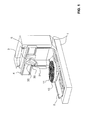
Die
Der Werkstücktisch 10 ist im Ausführungsbeispiel rund, hat eine horizontale Oberfläche und diese weist zur Befestigung eines Werkstückes auf diesem T-Nuten 11 auf. Der Tisch 10 ist um seine Achse 100 (siehe
An dem Maschinenständer 1 ist ein Kreuzschlitten 3 vertikal verfahrbar angeordnet. Der vertikale Kreuzschlitten 3, der an Rollenführungen am Maschinenständer 1 befestigt ist, ist auf der anderen Seite mit einer Querschiene 4 verbunden. An der Querschiene 4 ist ein horizontal verfahrbarer Kreuzschlitten 5 befestigt. Mit dem horizontalen Kreuzschlitten 5 ist der weiter unten zu beschreibende Fräskopfträger 20 verbunden. Insgesamt ist die Drehachse 52 (siehe
Bei dem hier dargestellten Ausführungsbeispiel ist also der Fräskopfträger 20 gegenüber dem Maschinenständer 1 sowohl horizontal als auch vertikal verfahrbar. In der in der
Es ist dabei natürlich unerheblich, ob an dem Maschinenständer 1 zuerst der vertikal verfahrbare Kreuzschlitten 3 und anschliessend der horizontal verfahrbare Kreuzschlitten 5 befestigt ist, an dem dann der Fräskopfträger 20 angeordnet ist. Die Anordnung der beiden Kreuzschlitten 3 und 5 kann auch genau andersherum vorgesehen sein, wie z.B. in der
Dabei ist die eine translatorische Verschiebung mit dem Werkstücktisch 10 gekoppelt, der um sich selbst drehbar ist. Die beiden anderen translatorische Verschiebungen sind dem Werkzeugträger 20 zugeordnet. Bei einer anderen Ausführungsform können auch zwei Verschiebungen mit dem Werkstücktisch 10 gekoppelt sein, zum Beispiel die Verfahrbarkeit in der horizontalen Ebene und nur die vertikale Verschiebung dem Werkzeugträger 20 zugeordnet sein. Prinzipiell können auch alle drei Verschiebungen an einem Element, also Werkstücktisch 10 oder Werkzeugträger 20, realisiert sein. Aus Stabilitätsgründen ist eine 2:1 Verteilung aber bevorzugt, im Gegensatz zu einer Verfahrbarkeit von allen drei Achsen von entweder dem Werkzeugträger 20 oder dem Werkzeugtisch 10.In this case, the one translational displacement is coupled to the workpiece table 10, which is rotatable about itself. The other two translational displacements are assigned to the
An dem Werkzeugträger 20 ist der Werkzeugkopf 21 über einer Fläche 30 befestigt, durch die eine Drehachse 52 definiert wird, wie in den weiteren Figuren zu sehen sein wird. In der Beschreibung wird statt des allgemeinen Begriffes Werkzeug und Werkzeugträger auch der Begriff Fräskopf verwendet, welches ein spezielles Werkzeug ist. Darunter sind auch andere spanende Bearbeitungswerkzeuge zu verstehen.On the
Somit sind die drei Drehbewegungen der Maschine ebenfalls verteilt. Die langsame Drehung des Werkstücktisches 10 um seine eigene Achse auf der einen Seite und die langsame Drehung des Werkzeugkopfes 21 um die schräg geneigte Achse 52 des Werkzeugträgers 20 andererseits.Thus, the three rotational movements of the machine are also distributed. The slow rotation of the workpiece table 10 about its own axis on one side and the slow rotation of the
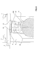
Die
Die
Die
Die
In der Zeichnung der
Die
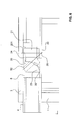
In allen Zeichnungen sind ähnliche Merkmale mit den gleichen Bezugszeichen versehen worden. Somit ist für den Werkzeugkopf 21 seine zentrale Achse 52 eingezeichnet, die die Achse 201 des Fräskopfes 21 an dessen Vorderkante schneidet. Dies ist im dargestellten Ausführungsbeispiel so vorbestimmt, der Schnittpunkt kann auch vor oder hinter der Achse 201 liegen. Aus der
Der Werkzeugträger 20 ist aus Stabilitätsgründen mit einem unteren Bereich als Abstützungskonsole 23 auf dem Horizonalkreuzschlitten 5 befestigt. Auf der anderen Seite ist der Werkzeugträger 20 mit im Querschnitt gegenüber der Achse als ein Polygonzug erkennbarer Struktur versehen. Man kann dies auch eine gegenüber der Achse 52 annähernd radialsymmetrische Struktur nennen. Wichtig ist die gegenüber seiner Hauptachse 52 vertikal ausgerichteten Anflanschfläche 30 für den Werkzeugkopf 21. Die nach oben als Polygonzug begrenzte Fläche, die auch halbzylindrisch sein könnte, gestattet einen grossen Bewegungsspielraum des Werkzeugkopfes 21 für eine Drehung desselben um die Hauptachse 52 des Werkzeugträgers 20. Vorteilhafterweise ragt der hintere Abschnitt 24 des Werkzeugkopfes 21 gar nicht oder möglichst wenig über die durch die Anflanschfläche 30 vorgegebene Ebene hinaus.For reasons of stability, the
Die
Der Winkel B gemäss dem Ausführungsbeispiel der Figuren beträgt 53 Grad. Er kann bei anderen Ausführungsbeispielen insbesondere einen Wert zwischen 46 und 60 annehmen. Der Winkel B legt den maximalen negativen Bearbeitungswinkel (der 90 Grad minus Wert von dem Winkel 303) dadurch fest, dass sich dieser aus (Wert B minus 45) mal 2 berechnet. Bei einem Winkel B von 53 Grad ergeben sich gerade 16 Grad. Ein solcher Winkel ist bei einem Einsatz der Anlage im allgemeinen Maschinenbau sinnvoll. Für den Einsatz der Maschine im Formenbau hingegen ist oft ein negativer Winkel von wenigen Grad ausreichend. Daher liegt die Bandbreite des Winkels B für den Einsatz im allgemeinen Maschinenbau beispielsweise zwischen 50 und 60 Grad, während für den Fonnenbau ein Winkel B zwischen 46 und 50 Grad eingesetzt werden kann.The angle B according to the embodiment of the figures is 53 degrees. It may in particular assume a value between 46 and 60 in other embodiments. The angle B sets the maximum negative machining angle (the 90 degrees minus the value of the angle 303) by calculating it from (value B minus 45) times 2. At an angle B of 53 degrees just 16 degrees. Such an angle is useful when using the plant in general engineering. For the use of the machine in the mold, however, a negative angle of a few degrees is often sufficient. Therefore, the bandwidth of the angle B for use in general engineering, for example, between 50 and 60 degrees, while for the civil engineering, an angle B between 46 and 50 degrees can be used.
Vorteilhaft ist, wenn die Achse 200 des Fräskopfes 21 und die Achse 52 des Werkzeugträgers 20 sich in einem Punkt 25 der Vorderseite 22 des Fräskopfes 21 treffen und kreuzen. Dies ist im dargestellten Ausführungsbeispiel so. Dieser Kreuzungspunkt kann auch im Werkzeug selber, zum Beispiel dort, wo die abspanende Handlung passiert, also vor der Vorderseite des Fräskopfs, angeordnet sein. Da die Linearachsen einen entsprechenden Abstand kompensieren müssen, ist die dargestellte Wahl ein Kompromiss zwischen Verfahrbarkeit der Maschine und Kraftübertragung.It is advantageous if the
Die
Neben diesen möglichen Extremalpositionen wird daher vorteilhafterweise ein mittlerer Winkel A zwischen dem maximalen Winkel C bei Horizontallage und dem Winkel = 0 Grad gewählt, der im Bereich zwischen 2/5 und 3/4 des Maximalwertes liegt, also bei einem Winkel B von 53 Grad, was zu einem Maximalwinkel von C von 41 Grad führt, sollte der Winkel A zwischen 16.4 und 30.8 Grad liegen. In bestimmten Anwendungsfällen kann es sinnvoll sein, den Maximalwert als Extremalposition zu wählen. Dies gilt insbesondere für die Extremalposition, bei welcher der Winkel C gemäss
Aus den Figuren ergibt sich in vorteilhafter Weise die Bearbeitbarkeit von negativen Winkeln, wie sie in der
Der Fachmann versieht die Werkzeugmaschine zur mehrachsigen Bearbeitung eines Werkstücks gemäss der Erfindung natürlich mit einer ihm bekannten elektronischen Ansteuerungs- und Kontrolleinheit auf, mit der die fünf Antriebe (drei translatorische Antriebe und zwei Drehantriebe) angesteuert werden, um ein auf dem Werkstücktisch 10 befestigtes Werkstück mit einem an dem Werkzeugkopf 21 befestigten Werkzeug abspanend zu bearbeiten. Dabei kann die gesteuerte Bearbeitung eines Werkstücks während einer Bewegung von Werkzeugtisch 10 oder Werkzeugkopf 21 als solchem von statten gehen, also zu einer Zeit, wenn ein oder mehrere Antriebe von einem oder mehreren der Bewegungsachsen aktiviert ist/sind. Insbesondere kann also die Bearbeitung bei einem Übergang von positiven zu negativen Bearbeitungswinkeln stufenlos vorgesehen sein. Es ist dabei eine simultane Bearbeitung von einer Ausrichtung vertikal gemäss
- AA
- Befestigungswinkel gegenüber der HorizontalenMounting angle relative to the horizontal
- BB
- Befestigungswinkel gegenüber der VertikalenMounting bracket relative to the vertical
- CC
- Winkel zwischen Fräskopf - Mittelachse bei horizontal ausgerichtetem FräskopfAngle between milling head - center axis with horizontally aligned milling head
- 11
- Maschinenständermachine stand
- 22
- Konsoleconsole
- 33
- vertikaler Kreuzschlittenvertical cross slide
- 44
- Querschienecross rail
- 55
- horizontaler Kreuzschlittenhorizontal cross slide
- 1010
- WerkstücktischWorktable
- 1111
- T-NutT-slot
- 2020
- Werkzeugträgertool carrier
- 2121
- Fräskopfmilling head
- 2222
- Vorderseite des FräskopfesFront of the milling head
- 2323
- Abstützungskonsolesupport console
- 2424
- hinterer Abschnittrear section
- 2525
- Kreuzungspunktintersection
- 3030
- Verbindungs- / AnflanschflächeConnection / flange surface
- 5151
- Senkrechte zu 5Vertical to 5
- 5252
- Drehachse WerkzeugkopfRotary axis tool head
- 5353
- Schnittpunktintersection
- 100100
- Achse WerkstücktischAxis workpiece table
- 200200
- Werkzeugachsetool axis
- 201201
-
Achse Fräskopf
Fig. 2 Axis milling headFig. 2 - 202202
-
Achse Fräskopf
Fig. 3 /8 Axis milling headFig. 3 /8th - 203203
-
Achse negativer Winkel
Fig.4 Axis of negative angleFigure 4 - 303303
- spitzer Winkelacute angle
Claims (9)
Priority Applications (1)
| Application Number | Priority Date | Filing Date | Title |
|---|---|---|---|
| EP10158931A EP2371482A1 (en) | 2010-04-01 | 2010-04-01 | Machine tool |
Applications Claiming Priority (1)
| Application Number | Priority Date | Filing Date | Title |
|---|---|---|---|
| EP10158931A EP2371482A1 (en) | 2010-04-01 | 2010-04-01 | Machine tool |
Publications (1)
| Publication Number | Publication Date |
|---|---|
| EP2371482A1 true EP2371482A1 (en) | 2011-10-05 |
Family
ID=42358436
Family Applications (1)
| Application Number | Title | Priority Date | Filing Date |
|---|---|---|---|
| EP10158931A Withdrawn EP2371482A1 (en) | 2010-04-01 | 2010-04-01 | Machine tool |
Country Status (1)
| Country | Link |
|---|---|
| EP (1) | EP2371482A1 (en) |
Cited By (2)
| Publication number | Priority date | Publication date | Assignee | Title |
|---|---|---|---|---|
| IT201600071094A1 (en) * | 2016-07-07 | 2018-01-07 | Uniteam S P A | MACHINE FOR PROCESSING PRISMATIC WOOD ELEMENTS |
| EP3593940A1 (en) | 2018-07-09 | 2020-01-15 | Reiden Technik AG | Machine tool |
Citations (6)
| Publication number | Priority date | Publication date | Assignee | Title |
|---|---|---|---|---|
| DE3432371A1 (en) * | 1983-11-30 | 1985-06-05 | Maschinenfabrik Heid Ag, Wien | TOOL CLAMPING HEAD |
| DE3407679C1 (en) * | 1984-03-02 | 1985-08-22 | Scharmann GmbH & Co, 4050 Mönchengladbach | Horizontal boring and milling machine with one by less than 45deg. spindle head tiltable to the horizontal inclined axis |
| EP0721819A1 (en) | 1994-12-14 | 1996-07-17 | DECKEL MAHO GmbH | Machine tool |
| DE10061934A1 (en) * | 2000-12-13 | 2002-06-27 | Deckel Maho Pfronten Gmbh | A workpiece table for a drilling or milling machine tool has a three dimensional motorized movement capability and control system to position the work to the tool |
| DE10252086A1 (en) * | 2002-11-08 | 2004-05-27 | Reiden Technik Ag | Machine tool, comprising two separate drives for working with high speed or high level of torque as required |
| WO2005108007A1 (en) * | 2004-05-10 | 2005-11-17 | Hpt Sinergy S.R.L. | Machine tool with a mono-rotatable spindle head and mono-rotatable workholding table |
-
2010
- 2010-04-01 EP EP10158931A patent/EP2371482A1/en not_active Withdrawn
Patent Citations (6)
| Publication number | Priority date | Publication date | Assignee | Title |
|---|---|---|---|---|
| DE3432371A1 (en) * | 1983-11-30 | 1985-06-05 | Maschinenfabrik Heid Ag, Wien | TOOL CLAMPING HEAD |
| DE3407679C1 (en) * | 1984-03-02 | 1985-08-22 | Scharmann GmbH & Co, 4050 Mönchengladbach | Horizontal boring and milling machine with one by less than 45deg. spindle head tiltable to the horizontal inclined axis |
| EP0721819A1 (en) | 1994-12-14 | 1996-07-17 | DECKEL MAHO GmbH | Machine tool |
| DE10061934A1 (en) * | 2000-12-13 | 2002-06-27 | Deckel Maho Pfronten Gmbh | A workpiece table for a drilling or milling machine tool has a three dimensional motorized movement capability and control system to position the work to the tool |
| DE10252086A1 (en) * | 2002-11-08 | 2004-05-27 | Reiden Technik Ag | Machine tool, comprising two separate drives for working with high speed or high level of torque as required |
| WO2005108007A1 (en) * | 2004-05-10 | 2005-11-17 | Hpt Sinergy S.R.L. | Machine tool with a mono-rotatable spindle head and mono-rotatable workholding table |
Cited By (2)
| Publication number | Priority date | Publication date | Assignee | Title |
|---|---|---|---|---|
| IT201600071094A1 (en) * | 2016-07-07 | 2018-01-07 | Uniteam S P A | MACHINE FOR PROCESSING PRISMATIC WOOD ELEMENTS |
| EP3593940A1 (en) | 2018-07-09 | 2020-01-15 | Reiden Technik AG | Machine tool |
Similar Documents
| Publication | Publication Date | Title |
|---|---|---|
| AT506486B1 (en) | TENSION DEVICE FOR A COMPUTER-CONTROLLED, SPANISH MACHINING MACHINE | |
| DE102004010984B3 (en) | Machine tool for machining a workpiece | |
| EP0232548B1 (en) | Work station for large work pieces | |
| CH629407A5 (en) | MACHINE TOOL. | |
| EP0812652A1 (en) | Device for manufacturing and/or assembling workpieces | |
| EP3027356A2 (en) | Machine tool for machining | |
| DE102010048435A1 (en) | Machine tool, particularly milling machine, has kinematics assembled in row that form less than six degrees of freedom, which affect on tool holder or work piece | |
| EP3288697A1 (en) | Machining system for aircraft structural components | |
| WO2016177452A1 (en) | Machine tool | |
| DE102015206567A1 (en) | Long turning lathe with two NC-controlled machining axes and method for machining workpieces on a lathe with two NC-controlled machining axes | |
| DE2044429C3 (en) | Additional device for machining the inner surfaces of spheres on a vertical lathe | |
| EP1106304A1 (en) | Machine Tool | |
| DE3636462A1 (en) | PNEUMATIC OR HYDRAULIC MEDIA OR LEADING SUPPORT ARM | |
| EP2371482A1 (en) | Machine tool | |
| DE202007009628U1 (en) | processing table | |
| EP1577040A1 (en) | Device for machining workpieces, in particular for workpieces provided with teeth | |
| DE1965040A1 (en) | Machine tool | |
| DE3503401C2 (en) | ||
| DE19609072A1 (en) | Three=dimensional positioning of tool holding plate | |
| DE102016124672A1 (en) | ECM machine tool and method for electrochemical machining | |
| EP3593940B1 (en) | Machine tool | |
| EP2848347B1 (en) | Device with variable configuration for sharpening saw blades | |
| WO1999016576A1 (en) | Machine tool | |
| DE102006015079B4 (en) | machine tool | |
| DE2105667A1 (en) | Machine tool |
Legal Events
| Date | Code | Title | Description |
|---|---|---|---|
| PUAI | Public reference made under article 153(3) epc to a published international application that has entered the european phase |
Free format text: ORIGINAL CODE: 0009012 |
|
| AK | Designated contracting states |
Kind code of ref document: A1 Designated state(s): AT BE BG CH CY CZ DE DK EE ES FI FR GB GR HR HU IE IS IT LI LT LU LV MC MK MT NL NO PL PT RO SE SI SK SM TR |
|
| AX | Request for extension of the european patent |
Extension state: AL BA ME RS |
|
| STAA | Information on the status of an ep patent application or granted ep patent |
Free format text: STATUS: THE APPLICATION IS DEEMED TO BE WITHDRAWN |
|
| 18D | Application deemed to be withdrawn |
Effective date: 20120406 |