EP3593940A1 - Machine tool - Google Patents
Machine tool Download PDFInfo
- Publication number
- EP3593940A1 EP3593940A1 EP19185313.4A EP19185313A EP3593940A1 EP 3593940 A1 EP3593940 A1 EP 3593940A1 EP 19185313 A EP19185313 A EP 19185313A EP 3593940 A1 EP3593940 A1 EP 3593940A1
- Authority
- EP
- European Patent Office
- Prior art keywords
- axis
- angle
- housing
- tool
- machine
- Prior art date
- Legal status (The legal status is an assumption and is not a legal conclusion. Google has not performed a legal analysis and makes no representation as to the accuracy of the status listed.)
- Granted
Links
- 238000003754 machining Methods 0.000 claims abstract description 44
- 238000003801 milling Methods 0.000 description 45
- 238000006073 displacement reaction Methods 0.000 description 7
- 230000001154 acute effect Effects 0.000 description 5
- 102000004315 Forkhead Transcription Factors Human genes 0.000 description 2
- 108090000852 Forkhead Transcription Factors Proteins 0.000 description 2
- 230000001419 dependent effect Effects 0.000 description 1
- 238000004519 manufacturing process Methods 0.000 description 1
- 238000012544 monitoring process Methods 0.000 description 1
- 239000007787 solid Substances 0.000 description 1
- 230000007704 transition Effects 0.000 description 1
Images


Classifications
-
- B—PERFORMING OPERATIONS; TRANSPORTING
- B23—MACHINE TOOLS; METAL-WORKING NOT OTHERWISE PROVIDED FOR
- B23Q—DETAILS, COMPONENTS, OR ACCESSORIES FOR MACHINE TOOLS, e.g. ARRANGEMENTS FOR COPYING OR CONTROLLING; MACHINE TOOLS IN GENERAL CHARACTERISED BY THE CONSTRUCTION OF PARTICULAR DETAILS OR COMPONENTS; COMBINATIONS OR ASSOCIATIONS OF METAL-WORKING MACHINES, NOT DIRECTED TO A PARTICULAR RESULT
- B23Q1/00—Members which are comprised in the general build-up of a form of machine, particularly relatively large fixed members
- B23Q1/25—Movable or adjustable work or tool supports
- B23Q1/44—Movable or adjustable work or tool supports using particular mechanisms
- B23Q1/50—Movable or adjustable work or tool supports using particular mechanisms with rotating pairs only, the rotating pairs being the first two elements of the mechanism
- B23Q1/54—Movable or adjustable work or tool supports using particular mechanisms with rotating pairs only, the rotating pairs being the first two elements of the mechanism two rotating pairs only
-
- B—PERFORMING OPERATIONS; TRANSPORTING
- B23—MACHINE TOOLS; METAL-WORKING NOT OTHERWISE PROVIDED FOR
- B23C—MILLING
- B23C1/00—Milling machines not designed for particular work or special operations
- B23C1/12—Milling machines not designed for particular work or special operations with spindle adjustable to different angles, e.g. either horizontal or vertical
-
- B—PERFORMING OPERATIONS; TRANSPORTING
- B23—MACHINE TOOLS; METAL-WORKING NOT OTHERWISE PROVIDED FOR
- B23Q—DETAILS, COMPONENTS, OR ACCESSORIES FOR MACHINE TOOLS, e.g. ARRANGEMENTS FOR COPYING OR CONTROLLING; MACHINE TOOLS IN GENERAL CHARACTERISED BY THE CONSTRUCTION OF PARTICULAR DETAILS OR COMPONENTS; COMBINATIONS OR ASSOCIATIONS OF METAL-WORKING MACHINES, NOT DIRECTED TO A PARTICULAR RESULT
- B23Q2220/00—Machine tool components
- B23Q2220/006—Spindle heads
Definitions
- the present invention relates to a machine tool for multi-axis machining of a workpiece in a clamping comprising a machine stand, a workpiece table movably arranged on the machine stand by means of a console and a tool head movably controllable on the machine stand, in particular a milling head.
- Such a machine tool is from the EP 0 721 819 is known in which the tool head is a vertical milling head, which is fastened vertically movable on a cross slide, the cross slide itself being fastened to the machine stand so as to be movable in the horizontal plane.
- the workpiece table is fastened on a support bracket which is fastened at an angle of 45 degrees downward on a support of the machine stand, in particular on the milling beam.
- the workpiece table can thus be rotated in its orientation about the axis of the support. In particular, it is not always arranged horizontally but can be rotated with respect to the machining axis of the vertical milling head.
- Such a machine tool according to the prior art has, in addition to the spindle of the vertical head, two axes of rotation and three translatory axes: a machining axis of rotation of the workpiece table and a third axis of rotation according to which the axis of rotation of the workpiece table is pivoted.
- the disadvantage here is that the two Slowly rotating axes that can be precisely adjusted require a connection in series on a support bracket.
- a so-called fork head is also known from the prior art, such as from the brochure of the Zimmermann company (www.f-neckmann.com).
- a swivel axis is arranged at right angles to the work spindle and can thus be swiveled around this axis as desired, which in turn allows negative machining positions even with only one axis.
- the disadvantage of the state of the art is that it is of a very solid design with little stability. The machining force is deflected at these angles up to several times by 90 °.
- the fork head is supported on both sides, but this limits the processing options.
- the ES 2 546 637 A1 shows an assembly of the angle housing, as in the WO 02/24401 can be seen.
- This angular housing is fixedly mounted on the movable carriage, so that only one axis of rotation is provided.
- a machine tool in which a first axis of rotation is provided horizontally, while a second axis of rotation is arranged at a 45 degree angle to the horizontal.
- the invention is based on the object of specifying an improved machine tool which has a higher precision in the setting of the workpiece table and tool. Another object of the invention is to permit the machining of angles less than 0 degrees in a simple manner, so that with a tool on a partial ball provided as a blank, this tool can be aligned normally on the blank surface in most tool positions. Finally, the setting of the tool in a horizontal orientation to the tool table should be improved and simplified.
- a machine tool for multi-axis machining of a workpiece in one clamping comprises a machine stand, a workpiece table arranged on the machine stand and a tool head holder attached to the machine stand, which is designed for the use of a tool rotating about a machining axis of the tool head holder.
- the workpiece table has a table level against which the angle housing defined below is aligned.
- the tool head holder can be moved in a relative movement relative to the workpiece table in three mutually perpendicular directions.
- An angle housing is now attached to the machine stand, the tool head holder being attached to the angle housing so that it can rotate about an adjustment axis at one end of the angle housing.
- angle housing is fastened to the machine stand such that it can be rotated about an angle housing axis, the angle housing axis in one of the table planes, mostly the horizontal or the vertical, deviating angle is aligned, and the angle housing axis and the adjustment axis are at an angle not equal to 0 degrees to one another.
- the angle between axes 51 and 52 is advantageously the same as the angle between axes 51 and 53, so that all positions on the workpiece ball used as a model can be approached continuously.
- the tool head holder holds a processing tool, which can be, among other things, a milling cutter or a turning tool.
- an angular housing was provided on the machine stand, on which the tool head holder was arranged at an angle to the horizontal axis and inclined from the horizontal.
- the angle housing can now also be rotated about an axis that is inclined with respect to the horizontal.
- this enables the setting of a wider angular range and, on the other hand, creates the possibility of approaching the horizontal and vertical machining positions corresponding to the axis of rotation of a tool by adjusting the axis of rotation of the tool head holder and the angle housing, regardless of the actual production angles for the axes of rotation.
- the milling head arrangement after the EP 0 408 264 A1 does not allow to move to all desired positions.
- the definition of desired positions is based on a spherical workpiece to be machined, after its positioning in the machine tool, the tool can be positioned anywhere in the "normal vector", i.e. the tip of the tool, eg a milling cutter, perpendicular to this workpiece to be machined Spherical shape stands. With the order after EP 0 408 264 A1 is this not possible.
- the tool head can face the machine stand in one or two of the three, and the workpiece table can be moved so as to be movable and controllable relative to the machine stand in two or one of the three directions perpendicular to one another.
- the angle housing axis of the angle housing with respect to the horizontal can have an inclined fastening angle between 10 and 80 degrees, more preferably between 15 and 75 degrees and in particular between 30 and 60 degrees.
- angles of 45 degrees are also advantageous.
- the angular housing axis of the angular housing and the setting axis of the angular housing can be arranged in one plane.
- the angular housing axis of the angular housing and the setting axis of the angular housing can also be arranged skew to one another.
- the angular housing axis of the angular housing can cut the machining axis of the tool head holder in the region of its front end surface.
- an advantage of the machine tool according to the invention lies in the fact that, due to the extended angle setting range for the tools, such as machining undercuts, long workpieces can be machined directly by moving them relative to the tool along three vertical axes without reclamping, the tool table can also be designed for rotation about an axis of rotation standing vertically to its surface.
- the workpieces are usually clamped on the milling table and the 30 ° in the lower position cannot usually be used for machining, since the milling head collides with the milling table or with the workpiece and there is usually very little machining on the workpieces at such angles. It is much more valuable to move the approachable area as far forward as possible, as in the present invention, since these angles are used much more often in machining than the lower angle in ES 2 546 637 A1 ,
- the invention allows the realization of a highly precise and at the same time extremely powerful machine tool.
- equipping the milling machine with a swivel head this permits five-sided machining in connection with a rotary table.
- the angular misalignment according to the present invention can still be done with the teaching of EP 2 371 482 can be combined so that the swivel range of 180 ° can be increased even further.
- pivot axis around the vertical axis is advantageously rotated through a sideways angle, that is to say that the main axis of the angular housing is then neither in a horizontally oriented nor in a vertically oriented plane, the deflection of the force can be restricted to a smaller angle. In return, longer travels have to be realized in order to achieve the same machining options.
- a compromise is a sideways angle of 25 to 30, especially 28 degrees.
- machining angles can be approached twice, which massively improves the accessibility to the workpiece. This applies, for example, to the two positions in which the work spindle is aligned vertically. On the one hand, this corresponds to the position of the Fig. 9 on the right side, to which a corresponding left-aligned position of the work spindle is possible. The same applies to machining in the horizontal, as "right” in the Fig. 7 is shown, for which there is a corresponding positioning "left".
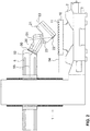
- the Fig. 1 shows a machine tool according to an embodiment of the invention.
- the machine tool comprises a machine stand 1, to which the moving parts are attached.
- the workpiece table 10 is on the bracket 2 in the horizontal direction corresponding to the table plane 54 (see Fig. 2 ) movable.
- the workpiece table 10 is angular in the exemplary embodiment, has a horizontal surface and this has T-slots 11 for fastening a workpiece on this.
- table 10 may be rotatable about a vertical axis.
- the machine tool is intended in particular for long workpieces that are not rotated on the tool table 10. This means that they can either be processed in one operation or they would have to be reclamped.
- the advantage of the invention here is that such substation work can be largely avoided.
- a workpiece, not shown in the drawings, can be fastened on the workpiece table 10 and can then be machined at different angles with the milling tool (also not shown) attached to a milling head 21. In the position of the Fig. 1 this is machining obliquely from above at right angles to the longitudinal direction of the table 10.
- a cross slide 3 is arranged vertically displaceably on the machine stand 1.
- the vertical cross slide 3, which is attached to roller guides on the machine stand 1, is on the other hand connected to a horizontally movable cross slide 5, which is movable here transversely to the longitudinal direction of the table. All positions X, Y and Z can be approached by the three linear displacements of the vertical cross slide, the horizontal cross slide and the table.
- the milling head carrier 20 to be described below is rotatably connected to the horizontal cross slide 5.
- the milling head carrier 20 is thus indirectly attached to the machine stand.
- the axis of rotation 52 (see Fig. 2 ) of the milling head carrier 20 inclined downwards.
- the rotatable tool head holder 21 is attached, which can rotate about an axis 51, which has an angle between 20 and 75, in particular 46 degrees, relative to the axis of rotation 52.
- the main axis of the milling head carrier 20 is also called the longitudinal axis 52 of the same.
- the axis of rotation of the tool (not shown) has the reference symbol 53 and is in the Fig. 2 aligned left down on the table 10.
- the angular housing or milling head carrier 20 can be moved both horizontally and vertically relative to the machine stand 1.
- the machine according to the invention has three translationally movable drives arranged perpendicular to one another, so that the tool (that is also the tool head holder 21) with respect to a workpiece (that is also with respect to the workpiece table 10) into the Space dimensions can be moved, that is, for example, on a workpiece provided as part of a ball, the tool can always be positioned perpendicular to the ball surface.
- a translatory displacement is coupled to the workpiece table 10.
- the other two translational displacements are assigned to the angular housing 20.
- two displacements can also be coupled to the workpiece table 10, for example the movability in the horizontal plane and only the vertical displacement assigned to the angular housing 20.
- all three displacements can also be realized on one element, ie workpiece table 10 or angle housing 20. For reasons of stability, a 2: 1 distribution is preferred, in contrast to the ability to move all three axes of either the angle housing 20 or the tool table 10.
- the tool head holder 21 is fastened to the angle housing 20 over a surface 30 through which an axis of rotation 52 is defined.
- the term milling head or milling head carrier is also used, since a tool used on the holder and rotating about the axis 53 can in particular be a special tool such as a milling cutter.
- other machining tools are also to be understood.
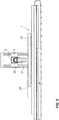
- the Fig. 2 now shows a section of the machine tool according to Fig. 1 with the workpiece table 10 and its T-slots 11, the elements 20 and 21 being aligned towards the front.
- the axis 51 of the angular housing 21 is not perpendicular to the machining table 10 in the position of the embodiment shown, since the sum of the angles of the axis 52 to the horizontal plus the inclination of the axis 51 of the tool carrier between 75 and 87 degrees, in particular between 80 and 85 degrees can be.
- the machining direction of the tool then corresponds to the axis of rotation 53, shown here in FIG an angle of 46 degrees.
- the axis 53 is aligned with the beam or horizontal cross slide 5 and thus allows a tool arranged below the surface 22 to machine angles less than 0 degrees if the vertical above the tool table 10 is designated 0 degrees.
- the angle between the axes 52 and 51 is equal to the angle between the axes 51 and 53; in the embodiment of the Fig. 2 53 degrees each.
- the Fig. 3 shows a plan view of the machine tool according to Fig. 1 , wherein it can be seen that all axes 51, 52 and 53 lie in the same plane, which corresponds to the plane of movement of the horizontal cross slide 5.
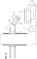
- the Fig. 4 shows a side view of the machine tool according to Fig. 1 with a milling head machining a negative angle.
- the representation is the representation of the Fig. 2 similar.
- the axis 53 of the tool head holder 21 intersects the horizontal axis 55 of the horizontal cross slide 5 at a negative angle, from bottom to top, which means nothing other than that the angle 105, indicated by a double arrow, is an acute angle, which is a machining of a workpiece from below.
- This position is achieved by turning the tool head 21 further relative to the angle housing 20, which is attached to the horizontal cross slide 5 at a further angle.
- the horizontal cross slide 5 moves rearward in the viewing direction of the Fig. 3 , Negative angles of 10 to 30 degrees are meaningful, that is, the reachability of a value of the acute angle 105 of 80 to 60 degrees with respect to the vertical.
- the Fig. 5 shows a front view of the workpiece table 10 Fig. 4 , in which it can be seen that all the tool elements 20 and 21 are arranged in the extension of the arm of the cross slide 5.
- the cross plate 3 of the vertical cross slide 3 is with With the help of the vertical cross slide 2, it can be moved up and down relative to the workpiece 10.
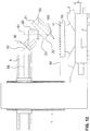
- the Fig. 6 shows a perspective view of the machine tool according to Fig. 1 with a horizontally aligned milling head.
- the axis of rotation 53 of the tool is in the viewing direction Fig. 6 horizontal on the right.
- This setting results from the sum of the angles of the angular housing, which is inclined with respect to the horizontal cross slide 5, and the inherent angle of the angular housing 20, here aligned by the rotation about the axis 52, such that the flange face of the milling head 21 is inclined laterally downwards is, in which case the axis of rotation 53 of the tool to be attached is horizontal.
- This setting is possible regardless of the exact angles of the axis of rotation 51 of the milling head 21 and the axis of rotation 52 of the angle housing 20
- the Fig. 7 shows a plan view of the machine tool according to Fig. 6 ,
- the downward-facing flange surface 30 is combined with a front side 23 of the angular housing, which is oriented to the right in the viewing direction, so that the milling head can be rotated horizontally.
- the Fig. 8 shows a front view of the tool table 1 with the milling head 21 Fig. 6 , from which it can be seen that the horizontal of the tool axis of rotation 53 runs below the longitudinal axis of the horizontal slide 5.
- FIG Fig. 4 The figures advantageously show the machinability of negative angles, as shown in FIG Fig. 4 are shown, since the angular housing 20 is inclined relative to the vertical (here: downward) (axis 55 to axis 52) and possibly laterally obliquely (as in FIG EP 2 371 482 ) is arranged.
- This makes it possible to move a machining head attached to this angular housing 20 into a position in which it attaches to the surface of the workpiece table 10 at an acute angle (axis 53 to the surface of the table 10) and thus permits negative machining angles with respect to this surface.
- a high stability of the machine can be achieved through the distribution of the two rotary drives, which specify the machining position, on the tool attachment and workpiece attachment.
- Fig. 9 shows a perspective view of the machine tool according to Fig. 1 with a vertically aligned milling head 21 and Fig. 10 shows a side view of the tool table 1 with the vertically aligned milling head 21;
- a person skilled in the art of course provides the machine tool for multi-axis machining of a workpiece according to the invention with an electronic control and monitoring unit known to him, with which the five or six setting drives (three translational drives and two to three rotary drives, the third rotary drive would be around a vertical axis rotatable tool table 10) and the machining axis 53 are controlled in order to machine a workpiece fastened on the workpiece table 10 with a tool fastened on the tool head 21.
- the controlled machining of a workpiece during a movement of the tool table 10 or tool head 21 as such can take place, that is to say at a time when one or more drives are / are activated by one or more of the movement axes.
- the machining can thus be provided continuously in the event of a transition from positive to negative machining angles. It is a simultaneous machining from an orientation according to vertical Fig. 2 until alignment negative according to Fig. 4 possible.
- the Fig. 11 shows a side view of another versus Fig. 1 slightly modified machine tool with angled housing at an angle.
- the angular housing axis 52 of the angular housing 20 is in the Fig. 2 arranged at an inclined angle of 30 degrees to the horizontal; now here in the Fig. 11
- this angle between the horizontal axis 55 of the beam 5 and the flange axis 52 was selected to be 45 degrees.
- Other exemplary embodiments lie with their angular ranges between 15 and 55 degrees and also beyond, as long as the angle housing 20 is flanged to the surface 30 with an inclination greater than 0 degrees and less than 90 degrees.
- the Fig. 12 shows a side view of another versus Fig. 11 slightly modified machine tool with angled housing 20 which is oriented obliquely at a different angle.
- the housing axis 52 of the housing 20 is here as in FIG Fig. 11 arranged at an inclination of 45 degrees to the horizontal; this angle between the horizontal axis 55 of the beam 5 and the flange axis 52 is 45 degrees.
- a tool 100 is also shown here, which projects beyond the front side 22 of the tool head 21.
- Fig. 11 here the angle between the axes 52 and 51 and the angle between the axes 51 and 53 are the same, but here equal to 45 degrees.
- This identical value of the angles between the axes 52 and 51 and between the axes 51 and 53 is not equal to zero and can advantageously be chosen between 30 and 60 degrees.
- the angle housing 20 itself has in the embodiment according to the Fig. 12 other angular relationships. Relative to the angles between axes 52 and 51 and between axes 51 and 53 in Fig. 11 has the execution after the Fig. 12 each a 45 ° arrangement. Except for the difference in the angles in components 20 and 21, the machine concept between the versions is as follows Fig. 11 and 12 identical.
- the angle between axes 51 and 52 is the same as the angle between axes 51 and 53, so that all positions on the workpiece ball used as a model can be approached continuously.
- There is also an angle between axes 52 and 55 so that axis 53 can be tilted as far forward as possible.
Abstract
Eine Werkzeugmaschine zur mehrachsigen Bearbeitung eines Werkstücks in einer Aufspannung umfasst einen Maschinenständer (1), einen an diesem angeordneten Werkstücktisch (10) und einen an dem Maschinenständer (1) befestigten Werkzeugkopfhalter (21), der für den Einsatz eines sich um eine Bearbeitungsachse (53) des Werkzeugkopfhalters (21) drehenden Werkzeuges ausgestaltet ist. Dabei ist der Werkzeugkopfhalter (21) in einer Relativbewegung gegenüber dem Werkstücktisch (10) in drei zueinander senkrecht verlaufenden Richtungen beweglich steuerbar verfahrbar. Ein Winkelgehäuse (20) ist an dem Maschinenständer (1) befestigt, wobei an einem Ende (23) von diesem der Werkzeugkopfhalter (21) um eine Einstellungsachse (51) drehbar an dem Winkelgehäuse (20) befestigt ist. Zusätzlich ist das Winkelgehäuse (20) um eine Winkelgehäuseachse (52) drehbar an dem Maschinenständer (1) befestigt, wobei die Winkelgehäuseachse (52) in einem von der Tischebene (54) abweichenden Winkel ausgerichtet ist, und wobei die Winkelgehäuseachse (52) und die Einstellungsachse (51) in einem Winkel ungleich 0 Grad zueinander stehen.A machine tool for multi-axis machining of a workpiece in one clamping comprises a machine stand (1), a workpiece table (10) arranged on this and a tool head holder (21) fastened to the machine stand (1), which is used for the use of a machining axis (53 ) of the tool head holder (21) rotating tool is designed. The tool head holder (21) is movably controllable in a relative movement with respect to the workpiece table (10) in three mutually perpendicular directions. An angle housing (20) is attached to the machine frame (1), at one end (23) of which the tool head holder (21) is attached to the angle housing (20) so as to be rotatable about an adjustment axis (51). In addition, the angular housing (20) is rotatably attached to the machine frame (1) about an angular housing axis (52), the angular housing axis (52) being oriented at an angle deviating from the table plane (54), and the angular housing axis (52) and the Adjustment axis (51) are at an angle not equal to 0 degrees to each other.
Description
Die vorliegende Erfindung betrifft eine Werkzeugmaschine zur mehrachsigen Bearbeitung eines Werkstücks in einer Aufspannung umfassend einen Maschinenständer, einen mittels einer Konsole am Maschinenständer beweglich angeordneten Werkstücktisch und einen an dem Maschinenständer beweglich steuerbar verfahrbaren Werkzeugkopf, insbesondere ein Fräskopf.The present invention relates to a machine tool for multi-axis machining of a workpiece in a clamping comprising a machine stand, a workpiece table movably arranged on the machine stand by means of a console and a tool head movably controllable on the machine stand, in particular a milling head.
Eine solche Werkzeugmaschine ist aus der
Eine solche Werkzeugmaschine gemäss dem Stand der Technik weist nebst der Spindel des Vertikalkopfes zwei Drehachsen und drei translatorische Achsen auf: eine Bearbeitungsdrehachse des Werkstücktisches und eine dritte Drehachse, gemäss der die Drehachse des Werkstücktisches verschwenkt wird. Hierbei ist nachteilig, dass die beiden präzis zu verstellenden langsamen Drehachsen einer Hintereinanderschaltung auf einer Tragkonsole bedürfen.Such a machine tool according to the prior art has, in addition to the spindle of the vertical head, two axes of rotation and three translatory axes: a machining axis of rotation of the workpiece table and a third axis of rotation according to which the axis of rotation of the workpiece table is pivoted. The disadvantage here is that the two Slowly rotating axes that can be precisely adjusted require a connection in series on a support bracket.
Bei der Anordnung gemäss der
Aus dem Stand der Technik sind weiter ein sogenannter Gabelkopf bekannt, wie aus dem Prospekt der Firma Zimmermann (www.f-zimmermann.com). Dabei ist eine Schwenkachse rechtwinklig zur Arbeitsspindel angeordnet und sie kann somit beliebig um diese Achse geschwenkt werden, was in der Folge auch bei nur einer Achse negative Bearbeitungslagen zulässt. Der Nachteil des Standes der Technik liegt in einer recht massiven Ausführung bei geringer Stabilität. Die Bearbeitungskraft wird in jedem Fall bei diesen Winkeln bis mehrmals um 90° umgelenkt. Der Gabelkopf ist dafür zwar beidseitig gelagert, aber das schränkt die Bearbeitungsmöglichkeiten ein.A so-called fork head is also known from the prior art, such as from the brochure of the Zimmermann company (www.f-zimmermann.com). A swivel axis is arranged at right angles to the work spindle and can thus be swiveled around this axis as desired, which in turn allows negative machining positions even with only one axis. The disadvantage of the state of the art is that it is of a very solid design with little stability. The machining force is deflected at these angles up to several times by 90 °. The fork head is supported on both sides, but this limits the processing options.
Aus der
Die
Aus der
Aus der
Aus der
Ausgehend von diesem Stand der Technik liegt der Erfindung die Aufgabe zu Grunde, eine verbesserte Werkzeugmaschine anzugeben, welche eine höhere Präzision in der Einstellung von Werkstücktisch und Werkzeug aufweist. Ferner ist es Ziel der Erfindung die Bearbeitung von Winkeln kleiner als 0 Grad in einfacher Weise zu gestatten, so dass mit einem Werkzeug auf einer als Rohling vorgesehenen Teil-Kugel jeweils in den meisten Werkzeugpositionen dieses Werkzeug normal auf der Rohlingoberfläche ausgerichtet werden kann. Schliesslich soll die Einstellung des Werkzeuges in horizontaler Ausrichtung zum Werkzeugtisch verbessert und vereinfacht werden.Starting from this prior art, the invention is based on the object of specifying an improved machine tool which has a higher precision in the setting of the workpiece table and tool. Another object of the invention is to permit the machining of angles less than 0 degrees in a simple manner, so that with a tool on a partial ball provided as a blank, this tool can be aligned normally on the blank surface in most tool positions. Finally, the setting of the tool in a horizontal orientation to the tool table should be improved and simplified.
Die Lösung der Ziele der vorliegenden Erfindung ist durch die Merkmale des Anspruchs 1 gekennzeichnet.The solution to the objectives of the present invention is characterized by the features of
Eine Werkzeugmaschine zur mehrachsigen Bearbeitung eines Werkstücks in einer Aufspannung umfasst einen Maschinenständer, einen am Maschinenständer angeordneten Werkstücktisch und einen an dem Maschinenständer befestigten Werkzeugkopfhalter, der für den Einsatz eines sich um eine Bearbeitungsachse des Werkzeugkopfhalters drehenden Werkzeuges ausgestaltet ist. Der Werkstücktisch hat eine Tischebene gegenüber der das weiter unten definierte Winkelgehäuse ausgerichtet ist. Dabei ist der Werkzeugkopfhalter in einer Relativbewegung gegenüber dem Werkstücktisch in drei zueinander senkrecht verlaufenden Richtungen beweglich steuerbar verfahrbar. Nun ist ein Winkelgehäuse an dem Maschinenständer befestigt, wobei an einem Ende des Winkelgehäuses der Werkzeugkopfhalter um eine Einstellungsachse drehbar an dem Winkelgehäuse befestigt ist. Zusätzlich ist das Winkelgehäuse um eine Winkelgehäuseachse drehbar an dem Maschinenständer befestigt, wobei die Winkelgehäuseachse in einem von der Tischebene, zumeist der Horizontalen oder der Vertikalen, abweichenden Winkel ausgerichtet ist, und wobei die Winkelgehäuseachse und die Einstellungsachse in einem Winkel ungleich 0 Grad zueinander stehen.A machine tool for multi-axis machining of a workpiece in one clamping comprises a machine stand, a workpiece table arranged on the machine stand and a tool head holder attached to the machine stand, which is designed for the use of a tool rotating about a machining axis of the tool head holder. The workpiece table has a table level against which the angle housing defined below is aligned. The tool head holder can be moved in a relative movement relative to the workpiece table in three mutually perpendicular directions. An angle housing is now attached to the machine stand, the tool head holder being attached to the angle housing so that it can rotate about an adjustment axis at one end of the angle housing. In addition, the angle housing is fastened to the machine stand such that it can be rotated about an angle housing axis, the angle housing axis in one of the table planes, mostly the horizontal or the vertical, deviating angle is aligned, and the angle housing axis and the adjustment axis are at an angle not equal to 0 degrees to one another.
Insbesondere ist vorteilhafterweise der Winkel zwischen Achsen 51 und 52 gleich wie der Winkel zwischen Achse 51 und 53, damit stufenlos alle Positionen auf der als Modell herhaltenden Werkstück-Kugel angefahren werden können. Dazu ist ein Winkel (ungleich 0 Grad) zwischen Achse 52 und 55 vorhanden, damit die Achse 53 möglichst weit nach vorne geneigt werden kann. Dies bringt beim Bearbeiten von Werkstücken grosse Vorteile gegenüber dem Stand der Technik.In particular, the angle between
Der Werkzeugkopfhalter hält ein Bearbeitungswerkzeug, welches unter anderem ein Fräser oder ein Drehmeissel sein kann.The tool head holder holds a processing tool, which can be, among other things, a milling cutter or a turning tool.
Bei der
Die Fräskopfanordnung nach der
Der Werkzeugkopf kann gegenüber dem Maschinenständer in einer oder zwei der drei, und der Werkstücktisch gegenüber dem Maschinenständer in zwei beziehungsweise einer der drei zueinander senkrecht verlaufenden Richtungen beweglich steuerbar verfahrbar sein.The tool head can face the machine stand in one or two of the three, and the workpiece table can be moved so as to be movable and controllable relative to the machine stand in two or one of the three directions perpendicular to one another.
Insbesondere kann die die Winkelgehäuseachse des Winkelgehäuses gegenüber der Horizontalen einen geneigten Befestigungswinkel zwischen 10 und 80 Grad, bevorzugter zwischen 15 und 75 Grad und insbesondere zwischen 30 und 60 Grad aufweisen. Vorteilhaft sind somit beispielsweise auch Winkel von 45 Grad.In particular, the angle housing axis of the angle housing with respect to the horizontal can have an inclined fastening angle between 10 and 80 degrees, more preferably between 15 and 75 degrees and in particular between 30 and 60 degrees. For example, angles of 45 degrees are also advantageous.
Die Winkelgehäuseachse des Winkelgehäuses und die Einstellungsachse des Winkelgehäuses können in einer Ebene angeordnet sein.The angular housing axis of the angular housing and the setting axis of the angular housing can be arranged in one plane.
Die Winkelgehäuseachse des Winkelgehäuses und die Einstellungsachse des Winkelgehäuses können auch windschief zueinander angeordnet sein.The angular housing axis of the angular housing and the setting axis of the angular housing can also be arranged skew to one another.
Die Winkelgehäuseachse des Winkelgehäuses kann die Bearbeitungsachse des Werkzeugkopfhalters im Bereich dessen vorderer Endfläche schneiden.The angular housing axis of the angular housing can cut the machining axis of the tool head holder in the region of its front end surface.
Obwohl ein Vorteil der Werkzeugmaschine nach der Erfindung darin liegt, dass durch den erweiterten Winkeleinstellbereichs für die Werkzeuge, wie eine Bearbeitung von Hinterschneidungen, lange Werkstücke direkt durch ein Verfahren von diesen gegenüber dem Werkzeug entlang von drei vertikal zueinander stehenden Achsen ohne ein Umspannen bearbeitbar sind, kann der Werkzeugtisch auch für eine Rotation um eine vertikal zu seiner Oberfläche stehende Drehachse ausgestaltet sein.Although an advantage of the machine tool according to the invention lies in the fact that, due to the extended angle setting range for the tools, such as machining undercuts, long workpieces can be machined directly by moving them relative to the tool along three vertical axes without reclamping, the tool table can also be designed for rotation about an axis of rotation standing vertically to its surface.
Diese Bearbeitungsoptionen entstehen durch den Winkel am Balken beziehungsweise dem Horizontalschlitten, der allerdings auch in einer anderen Richtung ausgerichtet sein kann. Im Allgemeinen ist er parallel zur Tischebene ausgerichtet. Der Vorteil von diesem Winkel im Balken ist die Verlagerung des anfahrbaren Bereichs. Eine Geometrie, wie sie in
Weitere Ausführungsformen sind in den abhängigen Ansprüchen angegeben.Further embodiments are specified in the dependent claims.
Die Erfindung gestattet die Realisierung einer hochpräzisen und zugleich äusserst kraftvollen Werkzeugmaschine. Durch die Ausstattung der Fräsmaschine mit einem Schwenkkopf gestattet dies im Zusammenhang mit einem Rundtisch eine Fünfseitenbearbeitung.The invention allows the realization of a highly precise and at the same time extremely powerful machine tool. By equipping the milling machine with a swivel head, this permits five-sided machining in connection with a rotary table.
Zusätzlich kann der Winkelversatz nach der vorliegenden Erfindung noch mit der Lehre der
Wenn vorteilhafterweise die Schwenkachse um die Vertikalachse herum noch um einen seitwärtigen Winkel gedreht wird, dass also dann Hauptachse des Winkelgehäuses weder in einer horizontal ausgerichteten noch in einer vertikal ausgerichteten Ebene gelegen ist, kann die Umlenkung der Kraft auf einen kleineren Winkel beschränkt werden. Dafür müssen im Gegenzug längere Verfahrwege realisiert werden, um die gleichen Bearbeitungsmöglichkeiten zu erreichen. Ein Kompromiss liegt bei einem seitwärtigen Winkel von 25 bis 30, insbesondere um 28 Grad.If the pivot axis around the vertical axis is advantageously rotated through a sideways angle, that is to say that the main axis of the angular housing is then neither in a horizontally oriented nor in a vertically oriented plane, the deflection of the force can be restricted to a smaller angle. In return, longer travels have to be realized in order to achieve the same machining options. A compromise is a sideways angle of 25 to 30, especially 28 degrees.
Ein Vorteil der Anordnung nach der Erfindung liegt auch darin, dass Bearbeitungswinkel doppelt angefahren werden können, was die Zugänglichkeit zum Werkstück massiv verbessert. Dies gilt zum Beispiel für die zwei Positionen, bei welchen die Arbeitsspindel vertikal ausgerichtet ist. Dies entspricht zum einen der Position der
Da die Werkzeugmaschine nach der Erfindung mit einer NC A- und B-Achse ausgestattet ist, können alle Winkelfehler der Mechanik durch die Kombination der beiden Drehachsen kompensiert werden. Dadurch steht das Werkzeug immer im gewünschten Bearbeitungswinkel.Since the machine tool according to the invention is equipped with an NC A and B axis, all mechanical angle errors can be compensated for by combining the two axes of rotation. This means that the tool is always at the desired machining angle.
Bevorzugte Ausführungsformen der Erfindung werden im Folgenden anhand der Zeichnungen beschrieben, die lediglich zur Erläuterung dienen und nicht einschränkend auszulegen sind. In den Zeichnungen zeigen:
- Fig. 1
- zeigt eine perspektivische Darstellung einer Werkzeugmaschine gemäss einem ersten Ausführungsbeispiel der Erfindung;
- Fig. 2
- zeigt eine Seitenansicht der Werkzeugmaschine gemäss
Fig. 1 mit schräg ausgerichtetem Fräskopf; - Fig. 3
- zeigt eine Draufsicht auf die Werkzeugmaschine gemäss
Fig. 1 ; - Fig. 4
- zeigt eine Seitenansicht der Werkzeugmaschine gemäss
Fig. 1 mit einem einen negativen Winkel bearbeitenden Fräskopf; - Fig. 5
- zeigt eine Vorderansicht auf den Werkstücktisch mit dem Fräskopf nach
Fig. 4 ; - Fig. 6
- zeigt eine perspektivische Ansicht der Werkzeugmaschine gemäss
Fig. 1 mit einem horizontal ausgerichteten Fräskopfs; - Fig. 7
- zeigt eine Draufsicht auf die Werkzeugmaschine gemäss
Fig. 6 ; - Fig. 8
- zeigt eine Vorderansicht auf den Werkstücktisch mit dem Fräskopf nach
Fig. 6 ; - Fig. 9
- zeigt eine perspektivische Ansicht der Werkzeugmaschine gemäss
Fig. 1 mit einem vertikal ausgerichteten Fräskopf; - Fig. 10
- zeigt eine Seitenansicht auf den Werkstücktisch mit dem Fräskopf nach
Fig. 9 ; - Fig. 11
- zeigt eine Seitenansicht eines zweiten Ausführungsbeispiels mit einer weiteren gegenüber der
Fig. 1 leicht abgewandelten Werkzeugmaschine mit schräg ausgerichtetem Winkelgehäuse; und - Fig. 12
- zeigt eine Seitenansicht eines dritten Ausführungsbeispiels mit einer weiteren gegenüber der
Fig. 1 leicht abgewandelten Werkzeugmaschine mit schräg ausgerichtetem Winkelgehäuse.
- Fig. 1
- shows a perspective view of a machine tool according to a first embodiment of the invention;
- Fig. 2
- shows a side view of the machine tool according to
Fig. 1 with angled milling head; - Fig. 3
- shows a top view of the machine tool according to
Fig. 1 ; - Fig. 4
- shows a side view of the machine tool according to
Fig. 1 with a milling head machining a negative angle; - Fig. 5
- shows a front view of the workpiece table with the milling head
Fig. 4 ; - Fig. 6
- shows a perspective view of the machine tool according to
Fig. 1 with a horizontally aligned milling head; - Fig. 7
- shows a top view of the machine tool according to
Fig. 6 ; - Fig. 8
- shows a front view of the workpiece table with the milling head
Fig. 6 ; - Fig. 9
- shows a perspective view of the machine tool according to
Fig. 1 with a vertically aligned milling head; - Fig. 10
- shows a side view of the workpiece table with the milling head
Fig. 9 ; - Fig. 11
- shows a side view of a second embodiment with another compared to the
Fig. 1 slightly modified machine tool with angled angular housing; and - Fig. 12
- shows a side view of a third embodiment with another compared to the
Fig. 1 slightly modified machine tool with angled angular housing.
Die
Der Werkstücktisch 10 ist im Ausführungsbeispiel eckig, hat eine horizontale Oberfläche und diese weist zur Befestigung eines Werkstückes auf diesem T-Nuten 11 auf. In anderen Ausführungsformen kann der Tisch 10 um eine vertikale Achse drehbar sein. Hier ist er es nicht, weil die Werkzeugmaschine insbesondere für lange Werkstücke vorgesehen ist, die nicht auf dem Werkzeugtisch 10 gedreht werden. Damit können sie entweder in einem Arbeitsgang bearbeitet werden oder sie müssten umgespannt werden. Hier liegt der Vorteil der Erfindung darin, dass solche Umspannarbeiten weitestgehend vermieden werden können. Auf dem Werkstücktisch 10 ist ein in den Zeichnungen nicht dargestelltes Werkstück befestigbar, welches dann mit dem an einem Fräskopf 21 befestigten Fräswerkzeug (ebenfalls nicht dargestellt) in verschiedenen Winkeln bearbeitbar ist. In der Position der
An dem Maschinenständer 1 ist ein Kreuzschlitten 3 vertikal verfahrbar angeordnet. Der vertikale Kreuzschlitten 3, der an Rollenführungen am Maschinenständer 1 befestigt ist, ist auf der anderen Seite mit einem horizontal verfahrbaren Kreuzschlitten 5 verbunden, der hier quer zur Längsrichtung des Tisches verfahrbar ist. Damit können alle Positionen X, Y und Z durch die drei Linearverschiebungen des vertikalen Kreuzschlittens, der horizontalen Kreuzschlittens und des Tisches angefahren werden.A
Mit dem horizontalen Kreuzschlitten 5 ist der weiter unten zu beschreibende Fräskopfträger 20 drehbar verbunden. Der Fräskopfträger 20 ist somit indirekt am Maschinenständer befestigt. Dabei ist die Drehachse 52 (siehe
Bei dem hier dargestellten Ausführungsbeispiel ist also das Winkelgehäuse oder Fräskopfträger 20 gegenüber dem Maschinenständer 1 sowohl horizontal als auch vertikal verfahrbar. In der in der
Es ist dabei natürlich unerheblich, ob an dem Maschinenständer 1 zuerst der vertikal verfahrbare Kreuzschlitten 3 und anschliessend der horizontal verfahrbare Kreuzschlitten 5 befestigt ist, an dem dann der Fräskopfträger 20 angeordnet ist. Die Anordnung der beiden Kreuzschlitten 3 und 5 kann auch genau andersherum vorgesehen sein, wie z.B. in der
Dabei ist die eine translatorische Verschiebung mit dem Werkstücktisch 10 gekoppelt. Die beiden anderen translatorische Verschiebungen sind dem Winkelgehäuse 20 zugeordnet. Bei einer anderen Ausführungsform können auch zwei Verschiebungen mit dem Werkstücktisch 10 gekoppelt sein, zum Beispiel die Verfahrbarkeit in der horizontalen Ebene und nur die vertikale Verschiebung dem Winkelgehäuse 20 zugeordnet sein. Prinzipiell können auch alle drei Verschiebungen an einem Element, also Werkstücktisch 10 oder Winkelgehäuse 20, realisiert sein. Aus Stabilitätsgründen ist eine 2:1 Verteilung aber bevorzugt, im Gegensatz zu einer Verfahrbarkeit von allen drei Achsen von entweder dem Winkelgehäuse 20 oder dem Werkzeugtisch 10.A translatory displacement is coupled to the workpiece table 10. The other two translational displacements are assigned to the
An dem Winkelgehäuse 20 ist der Werkzeugkopfhalter 21 über einer Fläche 30 befestigt, durch die eine Drehachse 52 definiert wird. In der Beschreibung wird statt des allgemeinen Begriffes Werkzeugkopfhalter und Winkelgehäuse auch der Begriff Fräskopf bzw. Fräskopfträger verwendet, da ein an dem Halter eingesetztes Werkzeug, welches um die Achse 53 rotiert, insbesondere ein spezielles Werkzeug wie ein Fräser sein kann. Es sind aber auch andere spanende Bearbeitungswerkzeuge zu verstehen.The
Zusätzlich bestehen Drehbewegungen der Maschine. Dies sind die langsame Drehung des Winkelgehäuses 20 um seine schräg geneigte Achse 52 am Kreuzschlitten 5 einerseits und die Drehung des Fräskopfs 21 mit dem eingesetzten Werkzeug (hier nicht dargestellt) um die Achse 51 andererseits.There are also rotary movements of the machine. These are the slow rotation of the
Die
Dabei ist die Achse 53 auf den Balken oder horizontalen Kreuzschlitten 5 ausgerichtet und erlaubt damit einen unterhalb der Fläche 22 angeordneten Werkzeug eine Bearbeitung von Winkeln kleiner 0 Grad, wenn mit 0 Grad die Senkrechte über dem Werkzeugtisch 10 bezeichnet wird.In this case, the
Insbesondere ist dabei der Winkel zwischen den Achsen 52 und 51 gleich zu dem Winkel zwischen den Achsen 51 und 53; bei dem Ausführungsbeispiel nach der
Die
Die
Die Achse 53 des Werkzeugkopfhalters 21 schneidet hier die horizontale Achse 55 des horizontalen Kreuzschlittens 5 unter einem negativen Winkel, von unten nach oben, was nichts anderes bedeutet, als dass der Winkel 105, angedeutet durch einen Doppelpfeil, ein spitzer Winkel ist, der eine Bearbeitung eines Werkstückes von unten her gestattet. Diese Position wird durch ein Weiterdrehen des Werkzeugkopfes 21 gegenüber dem Winkelgehäuse 20 erreicht, welcher in einem weiteren Winkel an dem horizontalen Kreuzschlitten 5 befestigt ist. Gleichzeitig verfährt der horizontale Kreuzschlitten 5 nach hinten in Blickrichtung der
Die
Die
Die
Die
Aus den Figuren ergibt sich in vorteilhafter Weise die Bearbeitbarkeit von negativen Winkeln, wie sie in der
Die
Der Fachmann versieht die Werkzeugmaschine zur mehrachsigen Bearbeitung eines Werkstücks gemäss der Erfindung natürlich mit einer ihm bekannten elektronischen Ansteuerungs- und Kontrolleinheit auf, mit der die fünf oder sechs Einstellungsantriebe (drei translatorische Antriebe und zwei bis drei Drehantriebe, der dritte Drehantrieb wäre der um eine Vertikalachse drehbare Werkzeugtisch 10) und die Bearbeitungsachse 53 angesteuert werden, um ein auf dem Werkstücktisch 10 befestigtes Werkstück mit einem an dem Werkzeugkopf 21 befestigten Werkzeug abspanend zu bearbeiten. Dabei kann die gesteuerte Bearbeitung eines Werkstücks während einer Bewegung von Werkzeugtisch 10 oder Werkzeugkopf 21 als solchem von statten gehen, also zu einer Zeit, wenn ein oder mehrere Antriebe von einem oder mehreren der Bewegungsachsen aktiviert ist/sind. Insbesondere kann also die Bearbeitung bei einem Übergang von positiven zu negativen Bearbeitungswinkeln stufenlos vorgesehen sein. Es ist dabei eine simultane Bearbeitung von einer Ausrichtung vertikal gemäss
Die
Die
Das Winkelgehäuse 20 selber hat bei dem Ausführungsbeispiel nach der
Claims (11)
Applications Claiming Priority (1)
| Application Number | Priority Date | Filing Date | Title |
|---|---|---|---|
| EP18182338 | 2018-07-09 |
Publications (2)
| Publication Number | Publication Date |
|---|---|
| EP3593940A1 true EP3593940A1 (en) | 2020-01-15 |
| EP3593940B1 EP3593940B1 (en) | 2023-06-28 |
Family
ID=62904298
Family Applications (1)
| Application Number | Title | Priority Date | Filing Date |
|---|---|---|---|
| EP19185313.4A Active EP3593940B1 (en) | 2018-07-09 | 2019-07-09 | Machine tool |
Country Status (1)
| Country | Link |
|---|---|
| EP (1) | EP3593940B1 (en) |
Citations (11)
| Publication number | Priority date | Publication date | Assignee | Title |
|---|---|---|---|---|
| EP0408264A1 (en) | 1989-07-11 | 1991-01-16 | Tai-Her Yang | A structural improvement for main shaft of tooling machine |
| US5413439A (en) * | 1994-03-18 | 1995-05-09 | Industrial Technology Research Institute | Universal spindle head for machine tool |
| EP0721819A1 (en) | 1994-12-14 | 1996-07-17 | DECKEL MAHO GmbH | Machine tool |
| WO2002024401A1 (en) | 2000-09-25 | 2002-03-28 | Fpt Industrie S.P.A. | Double-rotatable spindle head for machine tools |
| DE10252086A1 (en) | 2002-11-08 | 2004-05-27 | Reiden Technik Ag | Machine tool, comprising two separate drives for working with high speed or high level of torque as required |
| WO2005108007A1 (en) | 2004-05-10 | 2005-11-17 | Hpt Sinergy S.R.L. | Machine tool with a mono-rotatable spindle head and mono-rotatable workholding table |
| DE102006032443A1 (en) * | 2006-07-13 | 2008-01-17 | Wissner, Rolf, Dipl.-Ing. | Device for positioning tool in relation to workpiece, or workpiece in relation to tool, has angle of not more than 40 degrees between two pivot axes and angle between second pivot axis and principal direction of connecting element |
| EP2295200A1 (en) * | 2009-09-10 | 2011-03-16 | Klingelnberg AG | Tool head for use in a multi-axle machine, multi-axle machine with such a tool head and use of such a machine |
| EP2371482A1 (en) | 2010-04-01 | 2011-10-05 | Reiden Technik AG | Machine tool |
| ES2546637A2 (en) | 2014-03-24 | 2015-09-25 | Zayer, S.A. | Tool machine head (Machine-translation by Google Translate, not legally binding) |
| ITUB20161014A1 (en) * | 2016-02-24 | 2017-08-24 | Technai Team S R L | BIROTATIVE HEAD FOR MACHINE TOOL. |
-
2019
- 2019-07-09 EP EP19185313.4A patent/EP3593940B1/en active Active
Patent Citations (11)
| Publication number | Priority date | Publication date | Assignee | Title |
|---|---|---|---|---|
| EP0408264A1 (en) | 1989-07-11 | 1991-01-16 | Tai-Her Yang | A structural improvement for main shaft of tooling machine |
| US5413439A (en) * | 1994-03-18 | 1995-05-09 | Industrial Technology Research Institute | Universal spindle head for machine tool |
| EP0721819A1 (en) | 1994-12-14 | 1996-07-17 | DECKEL MAHO GmbH | Machine tool |
| WO2002024401A1 (en) | 2000-09-25 | 2002-03-28 | Fpt Industrie S.P.A. | Double-rotatable spindle head for machine tools |
| DE10252086A1 (en) | 2002-11-08 | 2004-05-27 | Reiden Technik Ag | Machine tool, comprising two separate drives for working with high speed or high level of torque as required |
| WO2005108007A1 (en) | 2004-05-10 | 2005-11-17 | Hpt Sinergy S.R.L. | Machine tool with a mono-rotatable spindle head and mono-rotatable workholding table |
| DE102006032443A1 (en) * | 2006-07-13 | 2008-01-17 | Wissner, Rolf, Dipl.-Ing. | Device for positioning tool in relation to workpiece, or workpiece in relation to tool, has angle of not more than 40 degrees between two pivot axes and angle between second pivot axis and principal direction of connecting element |
| EP2295200A1 (en) * | 2009-09-10 | 2011-03-16 | Klingelnberg AG | Tool head for use in a multi-axle machine, multi-axle machine with such a tool head and use of such a machine |
| EP2371482A1 (en) | 2010-04-01 | 2011-10-05 | Reiden Technik AG | Machine tool |
| ES2546637A2 (en) | 2014-03-24 | 2015-09-25 | Zayer, S.A. | Tool machine head (Machine-translation by Google Translate, not legally binding) |
| ITUB20161014A1 (en) * | 2016-02-24 | 2017-08-24 | Technai Team S R L | BIROTATIVE HEAD FOR MACHINE TOOL. |
Also Published As
| Publication number | Publication date |
|---|---|
| EP3593940B1 (en) | 2023-06-28 |
Similar Documents
| Publication | Publication Date | Title |
|---|---|---|
| EP0003244B2 (en) | Apparatus for locating workpieces | |
| DE10045176B4 (en) | machine tool | |
| DE10063628B4 (en) | Arrangement for translational positioning of a platform | |
| DE102005021640B4 (en) | Machine for processing optical workpieces, in particular plastic spectacle lenses | |
| DE102004010984B3 (en) | Machine tool for machining a workpiece | |
| EP0791438B1 (en) | Device for moving a body in space | |
| EP0812652B1 (en) | Device for manufacturing and/or assembling workpieces | |
| EP0659520A1 (en) | Machine-tool | |
| EP1590712A1 (en) | Method for controlling relative displacements of a tool against a workpiece | |
| EP1439934B1 (en) | Device for the displacement and/or positioning of an object in five axes | |
| EP2247405A2 (en) | Clamping device for a computer-controlled machining center | |
| DE202017100994U1 (en) | Crossbeam screw support device for machine tools in portal shape | |
| DE102009042579A1 (en) | Workpiece carrier, in particular rotary swivel table | |
| DE102007022200B4 (en) | Machine tool with numerical control | |
| EP0232548A2 (en) | Work station for large work pieces | |
| CH697397B1 (en) | Method and apparatus for grinding a profile of a workpiece. | |
| EP3456462A1 (en) | Machine tool for processing a workpiece | |
| WO1999032256A1 (en) | Machine tool for machining elongated workpieces | |
| EP3288697A1 (en) | Machining system for aircraft structural components | |
| DE10216571A1 (en) | Device for moving a working head in space | |
| EP1002621B2 (en) | Device for producing relative motion | |
| DE8336030U1 (en) | DEVICE FOR SWIVELING A TOOL-RECEIVING DEVICE, IN PARTICULAR AN ANGLE MILLING HEAD, AT THE FREE (LOWER) END OF A MILLING SPINDLE SLIDE | |
| WO2010089051A1 (en) | Machining center | |
| EP3593940B1 (en) | Machine tool | |
| WO2019020226A1 (en) | Machining facility for aircraft structural components |
Legal Events
| Date | Code | Title | Description |
|---|---|---|---|
| PUAI | Public reference made under article 153(3) epc to a published international application that has entered the european phase |
Free format text: ORIGINAL CODE: 0009012 |
|
| STAA | Information on the status of an ep patent application or granted ep patent |
Free format text: STATUS: THE APPLICATION HAS BEEN PUBLISHED |
|
| AK | Designated contracting states |
Kind code of ref document: A1 Designated state(s): AL AT BE BG CH CY CZ DE DK EE ES FI FR GB GR HR HU IE IS IT LI LT LU LV MC MK MT NL NO PL PT RO RS SE SI SK SM TR |
|
| AX | Request for extension of the european patent |
Extension state: BA ME |
|
| STAA | Information on the status of an ep patent application or granted ep patent |
Free format text: STATUS: REQUEST FOR EXAMINATION WAS MADE |
|
| 17P | Request for examination filed |
Effective date: 20200715 |
|
| RBV | Designated contracting states (corrected) |
Designated state(s): AL AT BE BG CH CY CZ DE DK EE ES FI FR GB GR HR HU IE IS IT LI LT LU LV MC MK MT NL NO PL PT RO RS SE SI SK SM TR |
|
| GRAP | Despatch of communication of intention to grant a patent |
Free format text: ORIGINAL CODE: EPIDOSNIGR1 |
|
| STAA | Information on the status of an ep patent application or granted ep patent |
Free format text: STATUS: GRANT OF PATENT IS INTENDED |
|
| INTG | Intention to grant announced |
Effective date: 20230124 |
|
| GRAS | Grant fee paid |
Free format text: ORIGINAL CODE: EPIDOSNIGR3 |
|
| GRAA | (expected) grant |
Free format text: ORIGINAL CODE: 0009210 |
|
| STAA | Information on the status of an ep patent application or granted ep patent |
Free format text: STATUS: THE PATENT HAS BEEN GRANTED |
|
| AK | Designated contracting states |
Kind code of ref document: B1 Designated state(s): AL AT BE BG CH CY CZ DE DK EE ES FI FR GB GR HR HU IE IS IT LI LT LU LV MC MK MT NL NO PL PT RO RS SE SI SK SM TR |
|
| REG | Reference to a national code |
Ref country code: CH Ref legal event code: EP |
|
| REG | Reference to a national code |
Ref country code: AT Ref legal event code: REF Ref document number: 1582273 Country of ref document: AT Kind code of ref document: T Effective date: 20230715 |
|
| REG | Reference to a national code |
Ref country code: IE Ref legal event code: FG4D Free format text: LANGUAGE OF EP DOCUMENT: GERMAN |
|
| REG | Reference to a national code |
Ref country code: DE Ref legal event code: R096 Ref document number: 502019008303 Country of ref document: DE |
|
| REG | Reference to a national code |
Ref country code: LT Ref legal event code: MG9D |
|
| PG25 | Lapsed in a contracting state [announced via postgrant information from national office to epo] |
Ref country code: SE Free format text: LAPSE BECAUSE OF FAILURE TO SUBMIT A TRANSLATION OF THE DESCRIPTION OR TO PAY THE FEE WITHIN THE PRESCRIBED TIME-LIMIT Effective date: 20230628 Ref country code: NO Free format text: LAPSE BECAUSE OF FAILURE TO SUBMIT A TRANSLATION OF THE DESCRIPTION OR TO PAY THE FEE WITHIN THE PRESCRIBED TIME-LIMIT Effective date: 20230928 |
|
| PGFP | Annual fee paid to national office [announced via postgrant information from national office to epo] |
Ref country code: CH Payment date: 20230801 Year of fee payment: 5 |
|
| REG | Reference to a national code |
Ref country code: NL Ref legal event code: MP Effective date: 20230628 |
|
| PG25 | Lapsed in a contracting state [announced via postgrant information from national office to epo] |
Ref country code: RS Free format text: LAPSE BECAUSE OF FAILURE TO SUBMIT A TRANSLATION OF THE DESCRIPTION OR TO PAY THE FEE WITHIN THE PRESCRIBED TIME-LIMIT Effective date: 20230628 Ref country code: NL Free format text: LAPSE BECAUSE OF FAILURE TO SUBMIT A TRANSLATION OF THE DESCRIPTION OR TO PAY THE FEE WITHIN THE PRESCRIBED TIME-LIMIT Effective date: 20230628 Ref country code: LV Free format text: LAPSE BECAUSE OF FAILURE TO SUBMIT A TRANSLATION OF THE DESCRIPTION OR TO PAY THE FEE WITHIN THE PRESCRIBED TIME-LIMIT Effective date: 20230628 Ref country code: LT Free format text: LAPSE BECAUSE OF FAILURE TO SUBMIT A TRANSLATION OF THE DESCRIPTION OR TO PAY THE FEE WITHIN THE PRESCRIBED TIME-LIMIT Effective date: 20230628 Ref country code: HR Free format text: LAPSE BECAUSE OF FAILURE TO SUBMIT A TRANSLATION OF THE DESCRIPTION OR TO PAY THE FEE WITHIN THE PRESCRIBED TIME-LIMIT Effective date: 20230628 Ref country code: GR Free format text: LAPSE BECAUSE OF FAILURE TO SUBMIT A TRANSLATION OF THE DESCRIPTION OR TO PAY THE FEE WITHIN THE PRESCRIBED TIME-LIMIT Effective date: 20230929 |
|
| PGFP | Annual fee paid to national office [announced via postgrant information from national office to epo] |
Ref country code: DE Payment date: 20230719 Year of fee payment: 5 |
|
| PG25 | Lapsed in a contracting state [announced via postgrant information from national office to epo] |
Ref country code: FI Free format text: LAPSE BECAUSE OF FAILURE TO SUBMIT A TRANSLATION OF THE DESCRIPTION OR TO PAY THE FEE WITHIN THE PRESCRIBED TIME-LIMIT Effective date: 20230628 |
|
| PG25 | Lapsed in a contracting state [announced via postgrant information from national office to epo] |
Ref country code: SK Free format text: LAPSE BECAUSE OF FAILURE TO SUBMIT A TRANSLATION OF THE DESCRIPTION OR TO PAY THE FEE WITHIN THE PRESCRIBED TIME-LIMIT Effective date: 20230628 |
|
| PG25 | Lapsed in a contracting state [announced via postgrant information from national office to epo] |
Ref country code: ES Free format text: LAPSE BECAUSE OF FAILURE TO SUBMIT A TRANSLATION OF THE DESCRIPTION OR TO PAY THE FEE WITHIN THE PRESCRIBED TIME-LIMIT Effective date: 20230628 |
|
| PG25 | Lapsed in a contracting state [announced via postgrant information from national office to epo] |
Ref country code: IS Free format text: LAPSE BECAUSE OF FAILURE TO SUBMIT A TRANSLATION OF THE DESCRIPTION OR TO PAY THE FEE WITHIN THE PRESCRIBED TIME-LIMIT Effective date: 20231028 |
|
| PG25 | Lapsed in a contracting state [announced via postgrant information from national office to epo] |
Ref country code: SM Free format text: LAPSE BECAUSE OF FAILURE TO SUBMIT A TRANSLATION OF THE DESCRIPTION OR TO PAY THE FEE WITHIN THE PRESCRIBED TIME-LIMIT Effective date: 20230628 Ref country code: SK Free format text: LAPSE BECAUSE OF FAILURE TO SUBMIT A TRANSLATION OF THE DESCRIPTION OR TO PAY THE FEE WITHIN THE PRESCRIBED TIME-LIMIT Effective date: 20230628 Ref country code: RO Free format text: LAPSE BECAUSE OF FAILURE TO SUBMIT A TRANSLATION OF THE DESCRIPTION OR TO PAY THE FEE WITHIN THE PRESCRIBED TIME-LIMIT Effective date: 20230628 Ref country code: PT Free format text: LAPSE BECAUSE OF FAILURE TO SUBMIT A TRANSLATION OF THE DESCRIPTION OR TO PAY THE FEE WITHIN THE PRESCRIBED TIME-LIMIT Effective date: 20231030 Ref country code: IS Free format text: LAPSE BECAUSE OF FAILURE TO SUBMIT A TRANSLATION OF THE DESCRIPTION OR TO PAY THE FEE WITHIN THE PRESCRIBED TIME-LIMIT Effective date: 20231028 Ref country code: ES Free format text: LAPSE BECAUSE OF FAILURE TO SUBMIT A TRANSLATION OF THE DESCRIPTION OR TO PAY THE FEE WITHIN THE PRESCRIBED TIME-LIMIT Effective date: 20230628 Ref country code: EE Free format text: LAPSE BECAUSE OF FAILURE TO SUBMIT A TRANSLATION OF THE DESCRIPTION OR TO PAY THE FEE WITHIN THE PRESCRIBED TIME-LIMIT Effective date: 20230628 Ref country code: CZ Free format text: LAPSE BECAUSE OF FAILURE TO SUBMIT A TRANSLATION OF THE DESCRIPTION OR TO PAY THE FEE WITHIN THE PRESCRIBED TIME-LIMIT Effective date: 20230628 |
|
| PG25 | Lapsed in a contracting state [announced via postgrant information from national office to epo] |
Ref country code: PL Free format text: LAPSE BECAUSE OF FAILURE TO SUBMIT A TRANSLATION OF THE DESCRIPTION OR TO PAY THE FEE WITHIN THE PRESCRIBED TIME-LIMIT Effective date: 20230628 |
|
| PG25 | Lapsed in a contracting state [announced via postgrant information from national office to epo] |
Ref country code: MC Free format text: LAPSE BECAUSE OF FAILURE TO SUBMIT A TRANSLATION OF THE DESCRIPTION OR TO PAY THE FEE WITHIN THE PRESCRIBED TIME-LIMIT Effective date: 20230628 |
|
| PG25 | Lapsed in a contracting state [announced via postgrant information from national office to epo] |
Ref country code: LU Free format text: LAPSE BECAUSE OF NON-PAYMENT OF DUE FEES Effective date: 20230709 |
|
| PG25 | Lapsed in a contracting state [announced via postgrant information from national office to epo] |
Ref country code: MC Free format text: LAPSE BECAUSE OF FAILURE TO SUBMIT A TRANSLATION OF THE DESCRIPTION OR TO PAY THE FEE WITHIN THE PRESCRIBED TIME-LIMIT Effective date: 20230628 Ref country code: LU Free format text: LAPSE BECAUSE OF NON-PAYMENT OF DUE FEES Effective date: 20230709 |