EP2371071B1 - Procédé et appareil pour transmettre un signal dans un système de communication sans fil - Google Patents
Procédé et appareil pour transmettre un signal dans un système de communication sans fil Download PDFInfo
- Publication number
- EP2371071B1 EP2371071B1 EP09836359.1A EP09836359A EP2371071B1 EP 2371071 B1 EP2371071 B1 EP 2371071B1 EP 09836359 A EP09836359 A EP 09836359A EP 2371071 B1 EP2371071 B1 EP 2371071B1
- Authority
- EP
- European Patent Office
- Prior art keywords
- signal
- data
- subframe
- guard time
- macro
- Prior art date
- Legal status (The legal status is an assumption and is not a legal conclusion. Google has not performed a legal analysis and makes no representation as to the accuracy of the status listed.)
- Active
Links
- 238000000034 method Methods 0.000 title claims description 41
- 238000004891 communication Methods 0.000 title claims description 28
- 230000006854 communication Effects 0.000 title claims description 28
- 230000005540 biological transmission Effects 0.000 claims description 46
- 238000013468 resource allocation Methods 0.000 claims description 25
- 238000013507 mapping Methods 0.000 claims 8
- 125000004122 cyclic group Chemical group 0.000 description 13
- 230000015654 memory Effects 0.000 description 8
- 230000008054 signal transmission Effects 0.000 description 5
- 230000008859 change Effects 0.000 description 4
- 238000007796 conventional method Methods 0.000 description 4
- 238000010586 diagram Methods 0.000 description 4
- 230000006870 function Effects 0.000 description 3
- 230000007774 longterm Effects 0.000 description 3
- 230000008569 process Effects 0.000 description 3
- 230000007175 bidirectional communication Effects 0.000 description 2
- 230000000694 effects Effects 0.000 description 2
- 238000005516 engineering process Methods 0.000 description 2
- 238000012986 modification Methods 0.000 description 2
- 230000004048 modification Effects 0.000 description 2
- 238000012545 processing Methods 0.000 description 2
- 230000002776 aggregation Effects 0.000 description 1
- 238000004220 aggregation Methods 0.000 description 1
- 230000003247 decreasing effect Effects 0.000 description 1
- GVVPGTZRZFNKDS-JXMROGBWSA-N geranyl diphosphate Chemical compound CC(C)=CCC\C(C)=C\CO[P@](O)(=O)OP(O)(O)=O GVVPGTZRZFNKDS-JXMROGBWSA-N 0.000 description 1
- 238000007726 management method Methods 0.000 description 1
- 238000005259 measurement Methods 0.000 description 1
- 238000010295 mobile communication Methods 0.000 description 1
- 230000008520 organization Effects 0.000 description 1
- 238000011160 research Methods 0.000 description 1
- 230000004044 response Effects 0.000 description 1
- 230000011218 segmentation Effects 0.000 description 1
- 230000006641 stabilisation Effects 0.000 description 1
- 238000011105 stabilization Methods 0.000 description 1
- 238000012546 transfer Methods 0.000 description 1
Images


Classifications
-
- H—ELECTRICITY
- H04—ELECTRIC COMMUNICATION TECHNIQUE
- H04B—TRANSMISSION
- H04B7/00—Radio transmission systems, i.e. using radiation field
- H04B7/24—Radio transmission systems, i.e. using radiation field for communication between two or more posts
- H04B7/26—Radio transmission systems, i.e. using radiation field for communication between two or more posts at least one of which is mobile
- H04B7/2603—Arrangements for wireless physical layer control
- H04B7/2606—Arrangements for base station coverage control, e.g. by using relays in tunnels
-
- H—ELECTRICITY
- H04—ELECTRIC COMMUNICATION TECHNIQUE
- H04B—TRANSMISSION
- H04B7/00—Radio transmission systems, i.e. using radiation field
- H04B7/14—Relay systems
- H04B7/15—Active relay systems
-
- H—ELECTRICITY
- H04—ELECTRIC COMMUNICATION TECHNIQUE
- H04B—TRANSMISSION
- H04B7/00—Radio transmission systems, i.e. using radiation field
- H04B7/14—Relay systems
- H04B7/15—Active relay systems
- H04B7/155—Ground-based stations
- H04B7/15507—Relay station based processing for cell extension or control of coverage area
-
- H—ELECTRICITY
- H04—ELECTRIC COMMUNICATION TECHNIQUE
- H04L—TRANSMISSION OF DIGITAL INFORMATION, e.g. TELEGRAPHIC COMMUNICATION
- H04L5/00—Arrangements affording multiple use of the transmission path
- H04L5/003—Arrangements for allocating sub-channels of the transmission path
- H04L5/0044—Arrangements for allocating sub-channels of the transmission path allocation of payload
-
- H—ELECTRICITY
- H04—ELECTRIC COMMUNICATION TECHNIQUE
- H04L—TRANSMISSION OF DIGITAL INFORMATION, e.g. TELEGRAPHIC COMMUNICATION
- H04L5/00—Arrangements affording multiple use of the transmission path
- H04L5/003—Arrangements for allocating sub-channels of the transmission path
- H04L5/0053—Allocation of signaling, i.e. of overhead other than pilot signals
-
- H—ELECTRICITY
- H04—ELECTRIC COMMUNICATION TECHNIQUE
- H04L—TRANSMISSION OF DIGITAL INFORMATION, e.g. TELEGRAPHIC COMMUNICATION
- H04L5/00—Arrangements affording multiple use of the transmission path
- H04L5/0091—Signaling for the administration of the divided path
-
- H—ELECTRICITY
- H04—ELECTRIC COMMUNICATION TECHNIQUE
- H04W—WIRELESS COMMUNICATION NETWORKS
- H04W72/00—Local resource management
- H04W72/20—Control channels or signalling for resource management
- H04W72/23—Control channels or signalling for resource management in the downlink direction of a wireless link, i.e. towards a terminal
-
- H—ELECTRICITY
- H04—ELECTRIC COMMUNICATION TECHNIQUE
- H04L—TRANSMISSION OF DIGITAL INFORMATION, e.g. TELEGRAPHIC COMMUNICATION
- H04L12/00—Data switching networks
- H04L12/02—Details
- H04L12/16—Arrangements for providing special services to substations
- H04L12/18—Arrangements for providing special services to substations for broadcast or conference, e.g. multicast
- H04L12/189—Arrangements for providing special services to substations for broadcast or conference, e.g. multicast in combination with wireless systems
Definitions
- the present invention relates to wireless communications, and more particularly, to a method of transmitting a signal in a wireless communication system employing a relay station.
- IMT-advanced which is a next generation (i.e., post 3 rd generation) mobile communication system are carried out in the international telecommunication union radio communication sector (ITU-R).
- IMT-advanced aims at support of an Internet protocol (IP)-based multimedia service with a data transfer rate of 1 Gbps in a stationary or slowly moving state or 100 Mbps in a fast moving state.
- IP Internet protocol
- 3 rd generation partnership project is a system standard satisfying requirements of the IMT-advanced, and prepares LTE-advanced which is an improved version of long term evolution (LTE) based on orthogonal frequency division multiple access (OFDMA)/single carrier-frequency division multiple access (SC-FDMA) transmission.
- LTE-advanced is one of promising candidates for the IMT-advanced.
- Technology related to a relay station is one of main technologies for the LTE-advanced.
- a relay station is a device for relaying a signal between a base station (BS) and a user equipment (UE), and is used for cell coverage extension and throughput enhancement of a wireless communication system.
- a conventional method of transmitting a signal between the BS and the UE has a problem when a signal is transmitted between the BS and the RS.
- the UE transmits the signal through one entire subframe in a time domain.
- One reason of transmitting a signal by the UE through the entire subframe is to set a duration of each channel for transmitting a signal to the maximum extent possible in order to reduce instantaneous maximum power consumed by the UE.
- the RS cannot transmit or receive a signal through one entire subframe from the perspective of the time domain.
- the RS relays a signal with respect to a plurality of UEs, which results in frequent occurrence of switching between a reception (Rx) mode and a transmission (Tx) mode.
- the switching between the Rx mode and the Tx mode requires a specific time (hereinafter referred to as a guard time) between an Rx-mode period and a Tx-mode period.
- the RS does not transmit or receive a signal in order to avoid inter- signal interference and to provide reliable operations.
- the RS may not be able to transmit or receive a signal through the entire subframe unlike in the UE. In this case, the conventional method of transmitting a signal between the BS and the UE cannot be directly used.
- the UE does not have to be directly used to transmit a signal between the BS and the RS in a sense that the RS is less restrictive in terms of power than the UE and that a channel state with respect to the BS is good in general.
- EP 1 915 005 A2 discloses an apparatus and a method for supporting a relay service in a multihop relay wireless communication system are provided.
- the method includes setting Tx/Rx mode switch region information of a Relay Station (RS).
- a signal is sent to a Mobile Station (MS) traveling in a service coverage during a first interval of a DownLink (DL) subframe according to resource allocation information.
- the mode switch region information and a signal are sent over a second interval of the DL subframe.
- the RS can communicate with a Base Station (BS) with accurate synchronization.
- BS Base Station
- the object of the present invention is to provide a method of transmitting a signal in a wireless communication system employing a relay station.
- a method of transmitting a signal of a base station in a wireless communication system including the features of claim 1.
- a base station including the features of claim 7.
- a signal can be effectively transmitted in a wireless communication system employing a relay station.
- LTE Long term evolution
- 3GPP 3 rd generation partnership project
- E-UMTS evolved-universal mobile telecommunications system
- E-UTRAN evolved-universal terrestrial radio access network
- the LTE employs an orthogonal frequency division multiple access (OFDMA) in a downlink and employs single carrier-frequency division multiplex access (SC-FDMA) in an uplink.
- OFDMA orthogonal frequency division multiple access
- SC-FDMA single carrier-frequency division multiplex access
- LTE-advance (LTE-A) is an evolution of the LTE.
- LTE/LTE-A technical features of the present invention are not limited thereto.
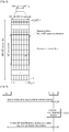
- FIG. 1 is a wireless communication system employing a relay station (RS).
- RS relay station
- a wireless communication system 10 employing an RS 12 includes at least one base station (BS) 11.
- Each BS 11 provides a communication service to a specific geographical region 15 generally referred to as a cell.
- the cell can be divided into a plurality of regions, and each region can be referred to as a sector.
- One or more cells may exist in the coverage of one BS.
- the BS 11 is generally a fixed station that communicates with a user equipment (UE) 13 and may be referred to as another terminology, such as an evolved node-B (eNB), a base transceiver system (BTS), an access point, etc.
- eNB evolved node-B
- BTS base transceiver system
- the BS 11 can perform functions such as connectivity between the RS 12 and a UE 14, management, control, resource allocation, etc.
- the RS 12 is a device for relaying a signal between the BS 11 and the UE 14, and is also referred to as another terminology such as a relay node (RN), a repeater, a relay, etc.
- a relay scheme used in the RS may be either amplify and forward (AF) or decode and forward (DF), and the technical features of the present invention are not limited thereto.
- the UEs 13 and 14 may be fixed or mobile, and may be referred to as another terminology, such as a mobile station (MS), a user terminal (UT), a subscriber station (SS), a wireless device, a personal digital assistant (PDA), a wireless modem, a handheld device, etc.
- a macro UE i.e., Ma UE 13 denotes a UE that directly communicates with the BS 11
- a relay UE i.e., Re UE
- the macro UE 13 can communicate with the BS 11 via the RS 12 to improve a data rate depending on a diversity effect.
- a downlink (DL) denotes communication from the BS 11 to the Ma UE 13
- an uplink (UL) denotes communication from the Ma UE 13 to the BS 11.
- a backhaul DL denotes communication from the BS 11 to the RS 12.
- a backhaul UL denotes communication from the RS 12 to the BS 11.
- the wireless communication system 10 employing the RS 12 is a system supporting bidirectional communication.
- the bidirectional communication may be performed by using a time division duplex (TDD) mode, a frequency division duplex (FDD) mode, etc.
- TDD time division duplex
- FDD frequency division duplex
- UL transmission and DL transmission use different time resources
- backhaul UL transmission and backhaul DL transmission use different time resources
- FDD mode UL transmission and DL transmission use different frequency resources
- backhaul UL transmission and backhaul DL transmission use different frequency resources.
- FIG. 2 shows a radio frame structure in a 3GPP LTE FDD mode.
- a radio frame consists of 10 subframes, and one subframe consists of two slots.
- a transmission time interval is defined as a time for transmitting one subframe.
- one subframe may have a length of 1 millisecond (ms), and one slot may have a length of 0.5 ms.
- FIG. 3 shows a radio frame structure in a 3GPP LTE TDD mode.
- one radio frame has a length of 10 ms and consists of two half- frames each having a length of 5 ms.
- One half-frame consists of five subframes each having a length of 1 ms.
- Each subframe is used as any one of an uplink (UL) subframe, a downlink (DL) subframe, and a special subframe.
- One radio frame includes at least one UL subframe and at least one DL subframe.
- One subframe consists of two slots. For example, one subframe may have a length of 1 ms, and one slot may have a length of 0.5 ms.
- the special subframe is a specific period located between the UL subframe and the DL subframe to separate a UL and a DL.
- One radio frame includes at least one special subframe.
- the special subframe includes a downlink pilot time slot (DwPTS), a guard period (GP), and an uplink pilot time slot (UpPTS).
- DwPTS is used for initial cell search, synchronization, or channel estimation.
- the UpPTS is used for channel estimation in a BS and UL transmission synchronization of a UE.
- the GP is used to remove interference that occurs between the UL and the DL due to a multipath delay of a signal.
- the GP may be included in a guard time.
- the radio frame structure is for exemplary purposes only, and thus the number of subframes included in the radio frame, the number of slots included in the subframe, or the number of orthogonal frequency division multiplexing (OFDM) symbols included in the slot may change variously.
- OFDM orthogonal frequency division multiplexing
- the section 4.1 of 3 GPP TS 36.211 V8.3.0 (2008-05) "Technical Specification Group Radio Access Network; Evolved Universal Terrestrial Radio Access (E-UTRA); Physical Channels and Modulation (Release 8) " explains the radio frame structure described with reference to FIG. 2 and FIG. 3 .
- one slot includes a plurality of OFDM symbols in a time domain and a plurality of resource blocks (RBs) in a frequency domain.
- the OFDM symbol is for expressing one symbol period since the 3GPP LTE uses OFDMA in a DL. According to a multiple access scheme, the OFDM symbol may be referred to as an SC-FDMA symbol or a symbol period.
- An RB is a resource allocation unit, and includes a plurality of consecutive subcarriers in one slot.
- FIG. 4 shows an example of a resource grid for one DL slot.
- a DL slot includes N DL symb OFDM symbols in a time domain.
- One resource block includes N RB sc subcarriers in a frequency domain.
- N DL symb may be 7 when using a normal cyclic prefix, and may be 6 when using an extended cyclic prefix.
- the number of OFDM symbols and the number of subcarriers for the resource block can be summarized by Table 1 below.
- One subframe includes 14 OFDM symbols when using the normal cyclic prefix, and includes 12 OFDM symbols when using the extended cyclic prefix.
- Each element on the resource grid is referred to as a resource element.
- the number N DL RB of RBs included in the DL slot depends on a DL transmission bandwidth determined in a cell.
- the values N DL symb and N RB sc are for exemplary purposes only, and the present invention is not limited thereto.
- FIG. 5 shows an example of a resource grid for one UL slot.
- a UL slot includes N UL symb SC-FDMA or OFDM symbols in a time domain, and includes a plurality of RBs in a frequency domain.
- Each RB includes N RB sc (e.g., 12) subcarriers.
- N UL symb may be 7 when using a normal cyclic prefix, and may be 6 when using an extended cyclic prefix.
- One subframe may include 14 SC-FDMA or OFDM symbols when using the normal cyclic prefix, and may include 12 SC-FDMA or OFDM symbols when using the extended cyclic prefix.
- N RB sc is 12 in one RB for example, the present invention is not limited thereto.
- the number N UL RB of RBs included in the UL slot depends on a UL transmission bandwidth determined in a cell.
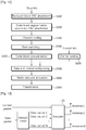
- FIG. 6 is a flowchart showing a method of transmitting a signal of an RS in a wireless communication system employing the RS.
- the RS first receives radio resource allocation information from a BS (step S100). Radio resources allocated by the radio resource allocation information will be described below in detail.
- the RS generates a multiplexed signal by multiplexing control information and data (step S200).
- the control information may imply a communication control related signal such as acknowledgment (ACK)/negative ACK (NACK) to be transmitted by the RS to the BS, a scheduling request signal, channel quality information (CQI), a buffer status report (BSR), etc.
- the data may imply a signal other than the control information, for example, may imply user data.
- the RS may configure each of the control information and the data into a control packet and a data packet, and may configure an aggregate packet which is an aggregation of the packets.
- the RS may multiplex the control packet and the data packet to generate a multiplexed signal.
- the RS may multiplex the aggregate packet to generate a multiplexed signal.
- FIG. 7 shows an example of configuring a control packet.
- FIG. 8 shows an example of configuring an aggregate packet.
- the control packet may include a control packet header, ACK/ NACK, a scheduling request (SR) signal, channel quality information (CQI), and a buffer status report (BSR).
- the ACK/NACK may be expressed by a bitmap to indicate whether several packets transmitted by a BS to an RS are successfully received. For example, if the BS has transmitted packets 1 to 5 in previous subframes and an error occurs in the packet 4, the bitmap can be expressed by 11101. Of course, the bitmap can also be expressed in an opposite manner, that is, 00010.
- an aggregate packet may include an aggregate packet header and a plurality of packets.
- the aggregate packet header may be set to a fixed length, or may be set in a semi-static manner such that the aggregate packet header is set to a predetermined length until a change signal is received and then changes its length according to the change signal when the change signal is received.
- a plurality of packets (i.e., packets 1 to 5) included in the aggregate packet may be control packets or data packets.
- the plurality of packets may be transmitted to the same UE, or may be transmitted to different UEs.
- Each of the plurality of packets may use a different modulation and coding scheme according to reliability, requirements on delay, whether the packet needs to be retransmitted or not, and so on.
- the aggregate packet header may include information regarding a modulation and coding scheme for the plurality of packets (i.e., packets 1 to 5).
- the control packet and the aggregate packet shown in FIG. 7 or FIG. 8 are for exemplary purposes only, and thus various modifications can be made.
- the RS transmits the multiplexed signal by using a radio resource indicated by the resource allocation information in a subframe (step S300).
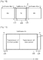
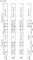
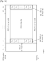
- FIG. 9 shows an example of allocating a radio resource by a BS to an RS and a UE.
- a subframe can be split into a control region and a data region.
- the control region is allocated with a physical uplink control channel (PUCCH) for carrying uplink control information.
- the data region is allocated with a physical uplink shared channel (PUSCH) for carrying user data.
- PUCCH physical uplink control channel
- PUSCH physical uplink shared channel
- Radio resources indicated by PUCCHs 1 to 4 in the control region can be used by a macro UE to carry an uplink control related signal to a BS.
- Examples of the uplink control related signal include a channel quality indicator (CQI), hybrid automatic repeat request (HARQ) ACK/NACK, etc.
- CQI channel quality indicator
- HARQ hybrid automatic repeat request
- Each of radio resources indicated by any one of PUSCHs 1 to 4 in the data region is allocated to an RS or the macro UE and is used to transmit a signal to the BS.
- a radio resource indicated by the PUSCH 2 may be allocated to the RS.
- the radio resource allocated to the RS includes a transmission period 100 and guard times 110 and 120 for transmission (Tx)/reception (Rx) switching of the RS in a time domain of a subframe.
- a frequency domain may include a specific frequency band of the data region other than the control region for transmitting control information to the macro UE.
- a region indicated by A is a radio resource region allocated to transmit a multiplexed signal by the RS to the BS, and is included in the transmission period 100 in the time domain and is included in the data region in the frequency domain. Accordingly, when a radio resource region of the guard time is added to a radio resource region allocated for signal transmission of the RS, a resultant radio resource appears as if it is a radio resource occupied by a PUSCH allocated to one macro UE.
- the macro UE and the RS can transmit signals to the BS in the allocated radio resource region by using a different multiplexing scheme.
- the macro UE can use an SC-FDMA scheme in the PUSCHs 1, 3, and 4, and the RS can use an OFDMA scheme in the PUSCH 2.
- the BS can receive a signal from the macro UE by using the SC-FDMA scheme, and can receive a signal from the RS by using the OFDMA scheme.
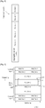
- FIG. 10 shows switching of an Rx mode and a Tx mode, performed by an RS.
- RX denotes signal reception
- TX denotes signal transmission.
- the RS receives a signal from a relay UE in a subframe #(n-1), transmits the signal to a BS in a subframe #n, and receives the signal again from the relay UE in a subframe #(n+1).
- an operation stabilization time is required depending on mode switching to avoid signal interference.
- Such a time is referred to guard times 110 and 120 (of course, such a guard time may be unnecessary when the RS operates in the same mode, for example, when signals are continuously received or transmitted in consecutive subframes).
- the guard times 110 and 120 are included in the subframe #n in which the RS transmits the signal.
- the relay UE transmits the signal through the entire subframe #(n-1) or #(n+1) since instantaneous maximum power has to be decreased by increasing a signal transmission time to the maximum extent possible due to a power problem. Therefore, it is preferable that the guard time is not provided in the subframes #(n-1) and #(n+1) in which the RS receives the signal from the relay UE.
- the guard times 110 and 120 are provided during at least one OFDM symbol in the subframe #n in which the RS transmits the signal (of course, the guard times 110 and 120 are unnecessary when the RS operates in the same mode, for example, when the signal is received or transmitted in all of the subframes #(n-1), #n, and #(n+1)).
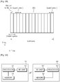
- FIG. 11 shows an example of transmitting a control packet and a data packet by an RS by using different time resources among allocated radio resources.
- the RS may first transmit the control packet in a transmission period 100 located between guard times 110 and 120 and thereafter transmit the data packet.
- the control packet and the data packet use different time resources, and thus can maintain orthogonality.
- FIG. 12 is a flowchart of a multiplexing process performed by an RS to transmit control information and data.
- data bits have a format of one transport block in every TTI.
- CRC cyclic redundancy check
- the CRC-attached bits are segmented in a code block unit, and the CRC parity bits are re-attached in the code block unit (step S200).
- Channel coding is performed on a bit sequence obtained by performing code block segmentation (step S300).
- the channel-coded bits are processed with rate matching (step S400), and code block concatenation is performed (step 500) to generate a data bit sequence.
- control information may be multiplexed together with data.
- the data and the control information may use different coding rates by allocating a different number of coded symbols for transmission of the data and the control information.
- Channel coding is performed on the control information (step S600) to generate a control information bit sequence.
- the data bit sequence and the control information bit sequence are multiplexed (step S700).
- the control information bit sequence may be first arranged, followed by arrangement of the data bit sequence.
- the multiplexed sequence is allocated to a radio resource (step S800), and is then transmitted (step S900).
- FIG. 13 is a block diagram for explaining an example of transmitting a control packet and a data packet by an RS by applying precoding.
- the RS applies precoding by using a precoder 131 while allowing a control packet and a data packet to use the same time resource and frequency resource, and thereafter transmits the resultant signal through a plurality of antennas 1 to M. Since the data packet has a greater size than the control packet in general, precoding may be applied after demultiplexing a plurality of data packets 1 to N by using a demultiplexer.
- control information may imply a communication control related signal such as ACK/NACK to be transmitted by the BS to the RS, a response on a scheduling request signal, radio resource allocation information, etc., and data may imply user data, that is, a signal other than the control information.
- the BS first allocates a radio resource for transmitting a signal to the RS or a macro UE. Then, the BS transmits the signal to the RS and the macro UE by using the allocated radio resource.
- the RS is allocated with a radio resource including the transmission period
- the macro UE is allocated with a radio resource including the guard time.
- the BS may transmit a first signal to the RS by using the allocated radio resource, and may transmit a second signal to the macro UE.
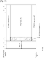
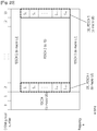
- FIG. 14 shows an example of allocating a radio resource in a subframe in which a BS transmits a signal to a macro UE and an RS.
- control information is transmitted to the macro UE in at least one OFDM symbol 161 located in a start part of the subframe (a region for transmitting control information to the macro UE is indicated by "PDCCH(to macro UE)" in FIG. 14 ).
- the control information includes radio resource allocation information regarding radio resource regions 165 and 166 for transmitting data to the macro UE.
- the radio resource regions 165 and 166 may include a guard time of the RS in a time domain.
- the BS transmits a first signal to the RS by using a radio resource 167 which is a consecutive specific band in a frequency domain and which includes a transmission period 163 in the time domain.
- the first signal may include both control information and data, each of which can be transmitted in a format of a control packet and a data packet.
- the present invention is not limited thereto, and thus transmission can be performed by using a plurality of separate frequency bands.
- at least any one of the plurality of frequency bands may be a frequency band pre-defined in consideration of a relation with the RS.
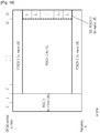
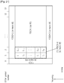
- FIG. 15 shows an example of transmitting a signal by a BS to one RS by using a plurality of frequency bands.
- the BS transmits a signal to the RS by using radio resources 168 and 169 indicated by a "PDSCH 2(P-PDSCH)" and a "PDSCH 4(S-PDSCH)” (hereinafter, respectively abbreviated to a PDSCH 2 and a PDSCH 4).
- control information e.g., radio resource allocation information
- a PDSCH (e.g., PDSCH 2) having the control information is referred to as a primary (P)-PDSCH, and the other PDSCH (e.g., PDSCH 4) other than the P-PDSCH is referred to as a secondary (S)-PDSCH.
- P primary
- S secondary
- a location of the P-PDSCH and a radio resource to be used may be pre-defined between the BS and the RS.
- the P-PDSCH (or a radio resource allocated to a control packet included in the P-PDSCH) may be designed to have a fixed format, location, and radio resource.
- the P-PDSCH may be fixed in a semi-static manner.
- the P-PDSCH may be designed to have a several number of limited formats, locations, and radio resources to facilitate blind decoding.
- the RS can obtain control information and data included in the P-PDSCH by performing blind decoding.
- the RS can directly decode the P-PDSCH without depending on an additional control channel (e.g., PDCCH).
- an additional control channel e.g., PDCCH
- the location of the S-PDSCH and information on the radio resource may be included in control information (i.e., radio resource allocation information) of the P-PDSCH.
- the S-PDSCH may exist in various locations in comparison with the P-PDSCH.
- the BS may split a subframe including a transmission period and a guard time in a time domain into a plurality of frequency bands in a frequency domain, and may transmit control information and first data to the RS by using a transmission period belonging to a first frequency band which is any one of the plurality of frequency bands.
- second data can be transmitted to the RS by using a transmission period belonging to a second frequency band indicated by the control information.
- FIG. 16 shows an operation of a BS, an RS, and a macro UE in a time domain when the BS transmits a signal to the RS or the macro UE.
- the BS transmits control information to the macro UE (i.e., Ma UE), and the RS transmits the control information to a relay UE (i.e., Re UE).
- the number of OFDM symbols for transmitting the control information may be equal or different between the BS and the RS.
- the BS transmits a second signal to the Ma UE during OFDM symbol periods 162 and 164 which correspond to a guard time from the perspective of the RS.
- the second signal may be data such as user data.
- the RS does not perform decoding.
- the BS transmits a first signal (e.g., control information and/or data) to the RS in an OFDM symbol period 163 other than the guard time in the subframe.
- the first signal transmitted by the BS to the RS includes a reference signal.
- the reference signal may be a dedicated reference signal.
- the Ma UE decodes a signal transmitted from the BS by using a radio resource corresponding to a guard time of the RS.
- the reference signal used for the RS or a cell-specific reference signal may be used.
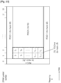
- FIG. 17 to FIG. 20 show examples of transmitting data by a BS to a macro UE by using a radio resource configured as a guard time from the perspective of an RS.
- the data may be user data.
- the BS maps data S 1 to data S k to radio resources 191 and 192 (hereinafter, abbreviated to a PDSCH 4 and a PDSCH 5) configured as a guard time, and then transmits the mapped data to the macro UE.
- radio resources 191 and 192 hereinafter, abbreviated to a PDSCH 4 and a PDSCH 5
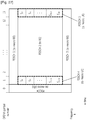
- FIG. 19 shows an example in which the data S 1 to the data S k are sequentially mapped in a frequency order to resource elements of a region 191 corresponding to the PDSCH 4, and thereafter data S k+1 to data S 2k are sequentially mapped in a frequency order in a region 192 corresponding to the PDSCH 5.
- FIG. 20 shows an example in which data is mapped first in a time order (e.g., the data S 1 is mapped to the region 191 corresponding to the PDSCH 4, and then the data S 2 is mapped to the region 192 corresponding to the PDSCH 5), and then the remaining part of data are mapped in a frequency order.
- data is mapped to OFDM symbol numbers 2 and 13.
- the PDCCH transmitted by the BS includes two OFDM symbols and the PDSCHs 4 and 5 (i.e., radio resources corresponding to a guard time of the RS) each include one OFDM symbol, this is for exemplary purposes only and the present invention is not limited thereto. Thus, various modifications can be made in the PDSCHs 4 and 5 when the PDCCH transmitted by the BS and the guard time of the RS have a different number of OFDM symbols.
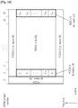
- FIG. 21 and FIG. 22 show examples in which a BS transmits data to a macro UE when a PDCCH has one OFDM symbol and a PDSCH 4 has two OFDM symbols.
- the BS maps data S 1 to data S k in a frequency order to resource elements in a first OFDM symbol time of a region 211 corresponding to the PDSCH 4, and thereafter maps data S k+1 to data S 2k in a frequency order to resource elements in a second OFDM symbol time.
- the BS maps data S 1 and data S 2 to resource elements, for example, having a highest frequency in a first OFDM symbol time and a second OFDM symbol time in a region 211 corresponding to the PDSCH 4, and sequentially maps data S 3 and data S 4 to resource elements having a next highest frequency. That is, data is mapped first in a time order and is then mapped in a frequency order.
- data is mapped to OFDM symbol numbers 1 and 2.
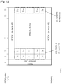
- FIG. 23 and FIG. 24 show examples in which a BS transmits data to a macro UE when a PDCCH allocated for the macro UE has one OFDM symbol, a PDSCH 4 has two OFDM symbols, and a PDSCH 5 has one OFDM symbol.
- the BS maps data S 1 to data S k in a frequency order to resource elements in a first OFDM symbol in a region 211 corresponding to the PDSCH 4, and thereafter maps data S k+1 to data S 2k in a frequency order to resource elements in a second OFDM symbol.
- the BS maps data S 2k+1 and data S 3k in a frequency order to resource elements in a region 232 corresponding to the PDSCH 5.
- the BS first maps data S 1 to data S 3 in a time order to resource elements in regions corresponding to the PDSCH 4 and the PDSCH 5, and then maps the remaining parts of data to resource elements having a low frequency in the same manner.
- data is mapped to OFDM symbol numbers 1, 2, and 13.
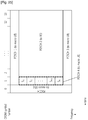
- FIG. 25 to FIG. 27 show examples in which a BS transmits data to a macro UE when a PDCCH allocated for the macro UE has one OFDM symbol and a PDSCH 4 or a PDSCH 5 has one OFDM symbol.
- FIG. 25 shows an example in which data S 1 to data S k are transmitted to the macro UE by being mapped in a frequency order to resource elements only in a PDSCH 4.
- FIG. 26 shows an example in which data S 1 to data S k and data S k+1 to S 2k are mapped in a frequency order to resource elements in a PDSCH 4 and a PDSCH 5.
- FIG. 27 shows an example in which data is first mapped in a time order to resource elements having the same frequency among resource elements belonging to a PDSCH 4 and a PDSCH 5 and is then mapped in a frequency order.
- data is mapped to an OFDM symbol number 1.
- FIG. 26 and FIG. 27 data is mapped to OFDM symbol numbers 1 and 13.
- the BS can transmit radio resource allocation information to the macro UE.
- the radio resource allocation information one-to-one corresponds to each method described with reference to FIG. 17 to FIG. 27 .
- the radio resource allocation information may include information for reporting a location of a guard time in a subframe or information for instructing puncturing of a transmission period.
- the information for reporting the location of the guard time may be configured by adding a new field consisting of a symbol allocation bitmap (3 bits) to a conventional DCI format.
- the symbol allocation bitmap can be expressed by Table 2 with respect to the methods described with reference to FIG. 17 to FIG. 24 . In Table 2, the method described with reference to FIG. 17 is simply referred to as ' FIG. 17 ' for convenience of explanation.
- Table 2 [Table 2] symbol allocation bitmap 001 010 011 110 111 exemplary allocation Fig. 18 Fig. 17 Fig. 19 or Fig. 20 Fig. 21 or Fig. 22 Fig. 23 or Fig. 24
- a first bit of the symbol allocation bitmap may indicate an OFDM symbol number 1
- a second bit thereof may indicate an OFDM symbol number 2
- a third bit thereof may indicate an OFDM symbol number 13.
- the macro UE can know a location of a guard time by using the symbol allocation bitmap.
- a 2-bit symbol allocation bitmap When a 2-bit symbol allocation bitmap is added as a new field, it can be expressed by Table 3 below. In this case, a first bit indicates an OFDM symbol number 2 of a subframe and a second bit thereof indicates an OFDM symbol number 13.
- Table 3 [Table 3] symbol allocation bitmap 01 10 11 exemplary allocation Fig. 18 Fig. 17 Fig. 19 or Fig. 20
- a first bit of the symbol allocation bitmap may indicate an OFDM symbol number 1 of a subframe, a second bit thereof may indicate an OFDM symbol number 13.
- the symbol allocation bitmap is expressed by Table 4 below.
- Table 4 [Table 4] symbol allocation bitmap 01 10 11 exemplary allocation Fig. 18 Fig. 25 Fig. 26 or Fig. 27
- the radio resource allocation information is information for instructing puncturing of a transmission period.
- the BS may instruct the macro UE to include the transmission period 163 and the guard times 162 and 164 in the time domain and to allocate a radio resource having a specific frequency band (i.e., a radio resource including the periods 165, 166, and 167). Thereafter, the BS may instruct the macro UE to decode only an OFDM symbol corresponding to the guard times 162 and 164 while puncturing an OFDM symbol corresponding to the transmission period 163 in the specific frequency band.
- the method of transmitting a signal by a BS in a wireless communication system employing an RS may apply, for example, when UL/DL band swapping is used between the BS and the RS.
- the UL/DL band swapping implies that the BS transmits a signal to the RS by using a UL frequency band in a specific subframe in an FDD mode.
- FIG. 28 shows an example of UL/DL band swapping.
- a BS transmits a signal to an RS in a subframe 4 belonging to a UL frequency band.
- the subframe 4 is referred to as a swapped subframe.
- a control packet may include scheduling information regarding signal transmission from the RS to the BS and scheduling information regarding next signal transmission from the BS to the RS.
- the aforementioned P-PDSCH and S-PDSCH may also apply to a case where the BS transmits a signal to the RS in a UL band by using the UL/DL band swapping.
- one PUSCH may be the P-PUSCH and the other PUSCH may be the S-PUSCH.
- 3GPP R1-084206, UL/DL band swapping for efficient support of relays in FDD mode, LG Electronics may be incorporated by reference for the purpose of explaining the UL/DL band swapping.
- the aforementioned method of transmitting the signal by the BS in the wireless communication system employing the RS may also apply to a case where the RS receives a signal from the BS by using a multicast/broadcast single frequency network (MBSFN) subframe.
- MBSFN multicast/broadcast single frequency network
- FIG. 29 shows an MBSFN subframe in which an RS receives a signal from a BS.
- the RS transmits control information of control channels (i.e., PCFICH, PDCCH, and PHICH) to a relay UE in a specific number of OFDM symbol periods (e.g., 2 OFDM symbol periods) of the MBSFN subframe.
- the control information reports that DL data is not transmitted to the relay UE.
- the control information can be used to prevent relay UEs from unnecessary data reception or reference signal measurement.
- the RS can receive a signal from the BS in a subframe period 291 other than guard times 1 and 2.
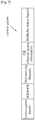
- FIG. 30 is a block diagram of a BS and an RS according to an embodiment of the present invention.
- a BS 50 includes a processor 51, a memory 53, and a radio frequency (RF) unit 52.
- the processor 51 splits a subframe including a transmission period and a guard time for Tx/Rx switching of the RS into a first frequency band and a second frequency band in a frequency domain, and transmits radio resource allocation information to the RS through the transmission period belonging to the first frequency band. Further, user data is transmitted to the RS through the transmission period belonging to a second frequency band indicated by the radio resource allocation information.
- the processor 51 may transmit a first signal to the RS through the transmission period by using the RF unit 52 in a subframe including the transmission period and the guard time for Tx/Rx switching of the RS, and may transmit a second signal to a macro UE through the guard time.
- Layers of a radio interface protocol can be implemented by the processor 51.
- the memory 53 is coupled to the processor 51, and stores a variety of information for operating the processor 51.
- the RF unit 52 is coupled to the processor 51, and transmits and/or receives a radio signal.
- An RS 60 includes a processor 61, a memory 62, and an RF unit 63.
- the processor 61 generates a multiplexed signal by multiplexing data and control information to be transmitted to the BS 50, and transmits the multiplexed signal by using a radio resource in a subframe indicated by radio resource allocation information received from the BS 50.
- the subframe includes a transmission period and a guard time for Tx/ Rx switching of the RS in a time domain.
- the radio resource is included in the transmission period.
- the processors 51 and 61 may include an application- specific integrated circuit (ASIC), a separate chipset, a logic circuit, and/or a data processing unit.
- the memories 52 and 62 may include a read-only memory (ROM), a random access memory (RAM), a flash memory, a memory card, a storage medium, and/or other equivalent storage devices.
- the RF units 53 and 63 may include a base-band circuit for processing a radio signal.
- the aforementioned methods can be implemented with a module (i.e., process, function, etc.) for performing the aforementioned functions.
- the module may be stored in the memories 52 and 62 and may be performed by the processors 51 and 61.
- the memories 52 and 62 may be located inside or outside the processors 51 and 61, and may be coupled to the processors 51 and 61 by using various well-known means.
Landscapes
- Engineering & Computer Science (AREA)
- Signal Processing (AREA)
- Computer Networks & Wireless Communication (AREA)
- Mobile Radio Communication Systems (AREA)
- Radio Relay Systems (AREA)
Claims (7)
- Procédé d'émission d'un signal d'une station de base (11, 50) utilisant une sous-trame comprenant une période d'émission et un temps de garde pour une commutation d'émission/réception d'une station de relais (12) dans un système de communication sans fil (10), le procédé comprenant :l'émission d'informations d'allocation de ressource à un macro équipement utilisateur (13) ;l'émission d'un premier signal à la station de relais (12) pendant la période d'émission ; etl'émission d'un second signal au macro équipement utilisateur (13) pendant le temps de garde,caractérisé par le fait quele second signal est mappé à des éléments de ressource appartenant au temps de garde par un premier procédé de mappage ou un second procédé de mappage, etles informations d'allocation de ressource informent le macro équipement utilisateur (13) concernant quel procédé est utilisé pour le second signal parmi le premier procédé de mappage et le second procédé.
- Procédé selon la revendication 1, dans lequel lorsque les informations d'allocation de ressource indiquent le premier procédé de mappage, des données d'utilisateur incluses dans le second signal sont mappées séquentiellement à des éléments de ressource ayant une première fréquence, et sont ensuite mappées séquentiellement à des éléments de ressource ayant une seconde fréquence parmi des éléments de ressource appartenant au temps de garde.
- Procédé selon la revendication 1, dans lequel lorsque les informations d'allocation de ressource indiquent le second procédé de mappage, des données d'utilisateur incluses dans le second signal sont mappées séquentiellement à des éléments de ressource ayant un premier numéro de symbole à multiplexage par répartition orthogonale de la fréquence, OFDM, et sont ensuite mappées séquentiellement à des éléments de ressource ayant un second numéro de symbole OFDM parmi des éléments de ressource appartenant au temps de garde.
- Procédé selon la revendication 1, dans lequel les informations d'allocation de ressource radio comprennent en outre des informations pour rapporter un emplacement du temps de garde ou des informations pour donner l'instruction d'une perforation de la période d'émission.
- Procédé selon la revendication 1, dans lequel le premier signal comprend des informations de commande et des données d'utilisateur, et les informations de commande et les données d'utilisateur consistent chacune en un paquet distinct.
- Procédé selon la revendication 1, dans lequel une sous-trame dans laquelle la station de relais reçoit le premier signal est une sous-trame de réseau monofréquence de diffusion/multidiffusion, MBSFN.
- Station de base (11, 50) utilisant une sous-trame comprenant une période d'émission et un temps de garde pour une commutation d'émission/réception d'une station de relais (12), la station de base (11) comprenant :une unité radiofréquence, RF, (52) configurée pour émettre et recevoir un signal radio ; etun processeur (51) couplé à l'unité RF, le processeur (51) étant configuré pour :émettre des informations d'allocation de ressource à un macro équipement utilisateur (13),émettre un premier signal à la station de relais pendant la période d'émission, etémettre un second signal au macro équipement utilisateur (13) pendant le temps de garde,caractérisée par le fait queledit processeur est en outre configuré pour mapper le second signal à des éléments de ressource appartenant au temps de garde par un premier procédé de mappage ou un second procédé de mappage, et pour émettre lesdites informations d'allocation de ressource pour informer le macro équipement utilisateur (13) concernant quel procédé est utilisé pour le second signal parmi le premier procédé de mappage et le second procédé.
Applications Claiming Priority (3)
| Application Number | Priority Date | Filing Date | Title |
|---|---|---|---|
| US14121208P | 2008-12-29 | 2008-12-29 | |
| KR1020090075227A KR101558593B1 (ko) | 2008-12-29 | 2009-08-14 | 무선통신 시스템에서 신호 전송 방법 및 장치 |
| PCT/KR2009/007830 WO2010077038A2 (fr) | 2008-12-29 | 2009-12-28 | Procédé et appareil pour transmettre un signal dans un système de communication sans fil |
Publications (3)
| Publication Number | Publication Date |
|---|---|
| EP2371071A2 EP2371071A2 (fr) | 2011-10-05 |
| EP2371071A4 EP2371071A4 (fr) | 2014-03-12 |
| EP2371071B1 true EP2371071B1 (fr) | 2017-03-29 |
Family
ID=44823404
Family Applications (1)
| Application Number | Title | Priority Date | Filing Date |
|---|---|---|---|
| EP09836359.1A Active EP2371071B1 (fr) | 2008-12-29 | 2009-12-28 | Procédé et appareil pour transmettre un signal dans un système de communication sans fil |
Country Status (6)
| Country | Link |
|---|---|
| US (3) | US8582419B2 (fr) |
| EP (1) | EP2371071B1 (fr) |
| JP (1) | JP5395190B2 (fr) |
| KR (1) | KR101558593B1 (fr) |
| CN (1) | CN102265527B (fr) |
| WO (1) | WO2010077038A2 (fr) |
Families Citing this family (30)
| Publication number | Priority date | Publication date | Assignee | Title |
|---|---|---|---|---|
| KR101558593B1 (ko) * | 2008-12-29 | 2015-10-20 | 엘지전자 주식회사 | 무선통신 시스템에서 신호 전송 방법 및 장치 |
| RU2529556C2 (ru) * | 2009-01-29 | 2014-09-27 | Панасоник Корпорэйшн | Устройство базовой станции и способ передачи |
| JP2012520621A (ja) * | 2009-03-13 | 2012-09-06 | リサーチ イン モーション リミテッド | 中継受信同調化システムおよびその方法 |
| KR101506576B1 (ko) * | 2009-05-06 | 2015-03-27 | 삼성전자주식회사 | 무선 통신 시스템에서 백홀 서브프레임 채널 송수신 방법 및 이를 위한 장치 |
| US9584215B2 (en) | 2009-05-08 | 2017-02-28 | Lg Electronics Inc. | Relay node and method for receiving a signal from a base station in a mobile communication system |
| KR101722779B1 (ko) * | 2009-08-14 | 2017-04-05 | 삼성전자주식회사 | 통신 시스템에서 자원 할당 장치 및 방법 |
| US8599736B2 (en) * | 2009-08-19 | 2013-12-03 | Nokia Corporation | Method and apparatus for transmission mode selection in cooperative relay |
| JP5072999B2 (ja) * | 2010-04-05 | 2012-11-14 | 株式会社エヌ・ティ・ティ・ドコモ | 無線通信制御装置及び無線通信制御方法 |
| EP2503727A1 (fr) * | 2011-03-23 | 2012-09-26 | Panasonic Corporation | Espace de recherche pour l'allocation de liaison montante dans un système de communication mobile à porteurs aggregés |
| US11696300B2 (en) | 2011-10-29 | 2023-07-04 | Comcast Cable Communications, Llc | Configuration of reduced transmission power time intervals based on traffic load |
| US8929215B2 (en) | 2011-10-29 | 2015-01-06 | Ofinno Technologies, Llc | Special subframe allocation in heterogeneous network |
| US9049724B2 (en) | 2011-10-29 | 2015-06-02 | Ofinno Technologies, Llc | Dynamic special subframe allocation |
| US8937918B2 (en) | 2011-10-29 | 2015-01-20 | Ofinno Technologies, Llc | Efficient special subframe allocation |
| US8971250B2 (en) | 2011-10-29 | 2015-03-03 | Ofinno Technologies, Llc | Special subframe allocation |
| US8873467B2 (en) | 2011-12-05 | 2014-10-28 | Ofinno Technologies, Llc | Control channel detection |
| US8934436B2 (en) | 2011-12-31 | 2015-01-13 | Ofinno Technologies, L.L.C. | Special subframe configuration in wireless networks |
| US9819462B2 (en) * | 2012-01-30 | 2017-11-14 | Alcatel Lucent | Method and apparatus for signaling to support flexible reference signal configuration |
| US9485758B2 (en) * | 2012-03-16 | 2016-11-01 | Lg Electronics Inc. | Method and apparatus for uplink transmission |
| US20130301498A1 (en) * | 2012-05-14 | 2013-11-14 | Qualcomm Incorporated | Scheme and apparatus for multirab enhancements with keeping both circuit-switched voice call and packet-switched data session alive |
| US20150071213A1 (en) * | 2012-05-14 | 2015-03-12 | Kari Pekka Pajukoski | Uplink Signalling Overhead |
| KR101429339B1 (ko) | 2012-06-29 | 2014-08-12 | 인텔렉추얼디스커버리 주식회사 | 매크로 간섭 회피를 위한 방법 및 장치 |
| US8873455B2 (en) * | 2013-02-15 | 2014-10-28 | General Dynamics C4 Systems, Inc. | Communication units and methods for relay-assisted uplink communication |
| US8929277B2 (en) * | 2013-02-15 | 2015-01-06 | General Dynamics C4 Systems, Inc. | Communication units and methods for relay-assisted uplink communication |
| US9287964B2 (en) | 2013-03-11 | 2016-03-15 | Intel Corporation | Millimeter-wave relay device with bounded delay and method for retransmission of symbols |
| KR102139721B1 (ko) * | 2013-08-29 | 2020-07-30 | 삼성전자주식회사 | 다중 경로 프로토콜에서 이중으로 네트워크 코딩을 적용하는 방법 및 그 장치 |
| EP4054091A1 (fr) | 2013-12-04 | 2022-09-07 | Telefonaktiebolaget LM Ericsson (publ) | Raccourcissement de sous-trame de liaison descendante dans des systèmes de duplexage temporel cellulaire (tdd) |
| EP4311127A3 (fr) * | 2013-12-04 | 2024-04-10 | Telefonaktiebolaget LM Ericsson (publ) | Raccourcissement de sous-trames de liaison montante dans des systèmes en duplexage par répartition dans le temps (tdd) |
| EP3273731A4 (fr) * | 2015-03-20 | 2019-03-06 | NTT DoCoMo, Inc. | Dispositif utilisateur et station de base |
| US10681633B2 (en) * | 2016-04-05 | 2020-06-09 | Qualcomm Incorporated | Configurable subframe structures in wireless communication |
| WO2019152071A1 (fr) | 2018-02-01 | 2019-08-08 | Garland Commercial Industries, Llc | Dispositif de cuisson bilatérale à mécanisme de verrouillage de position de plateau supérieur permettant une cuisson à réglage de positionnement par compression haute précision |
Family Cites Families (18)
| Publication number | Priority date | Publication date | Assignee | Title |
|---|---|---|---|---|
| JPH05184703A (ja) | 1991-07-16 | 1993-07-27 | Lassale Jean Bouchet | 補強部材を備えたゴルフ手袋 |
| US7133352B1 (en) * | 1999-09-20 | 2006-11-07 | Zion Hadad | Bi-directional communication channel |
| EP1848165A3 (fr) | 2006-04-19 | 2011-05-04 | Samsung Electronics Co., Ltd. | Service de relais dans un système de communications d'accès sans fil large bande à sauts multiples |
| GB2440985A (en) * | 2006-08-18 | 2008-02-20 | Fujitsu Ltd | Wireless multi-hop communication system |
| CN101141171B (zh) * | 2006-09-08 | 2011-07-06 | 华为技术有限公司 | 一种无线通信装置、系统及方法 |
| KR100961746B1 (ko) * | 2006-10-02 | 2010-06-07 | 삼성전자주식회사 | 다중 홉 중계방식을 사용하는 무선통신시스템에서 자원할당 장치 및 방법 |
| KR100948550B1 (ko) * | 2006-10-20 | 2010-03-18 | 삼성전자주식회사 | 다중홉 릴레이 방식을 사용하는 광대역 무선접속시스템에서 제어정보 통신 장치 및 방법 |
| KR20080035959A (ko) * | 2006-10-20 | 2008-04-24 | 삼성전자주식회사 | 다중 홉 중계방식을 사용하는 광대역 무선접속통신시스템에서 중계 서비스를 지원하기 위한 장치 및 방법 |
| JP4628411B2 (ja) * | 2006-10-20 | 2011-02-09 | 三星電子株式会社 | マルチホップ中継方式を用いる無線通信システムにおける中継サービスを支援するための装置及び方法 |
| EP1940189B1 (fr) | 2006-12-27 | 2020-04-15 | Samsung Electronics Co., Ltd. | Appareil et procédé de calcul d'une allocation de ressources d'une station relais |
| US20080220716A1 (en) * | 2007-03-06 | 2008-09-11 | Institute For Information Industry | Communication system and handshake method thereof |
| JP5154582B2 (ja) * | 2007-03-09 | 2013-02-27 | ゼットティーイー(ユーエスエー)インコーポレーテッド | マルチホップ中継局を有するワイヤレスセルラネットワークにおける無線リソース管理 |
| US8477633B2 (en) * | 2008-10-01 | 2013-07-02 | Lg Electronics Inc. | Method and apparatus for wireless resource allocation for relay in wireless communication system |
| BRPI0919959B1 (pt) * | 2008-10-30 | 2020-11-24 | Apple Inc. | sistema de comunicação via rádio sem fio e método de comunicação de uma transmissão de pacotes |
| US20100120442A1 (en) * | 2008-11-12 | 2010-05-13 | Motorola, Inc. | Resource sharing in relay operations within wireless communication systems |
| US9084283B2 (en) * | 2008-11-19 | 2015-07-14 | Qualcomm Incorporated | Peer-to-peer communication using a wide area network air interface |
| KR101558593B1 (ko) * | 2008-12-29 | 2015-10-20 | 엘지전자 주식회사 | 무선통신 시스템에서 신호 전송 방법 및 장치 |
| JP2012520621A (ja) * | 2009-03-13 | 2012-09-06 | リサーチ イン モーション リミテッド | 中継受信同調化システムおよびその方法 |
-
2009
- 2009-08-14 KR KR1020090075227A patent/KR101558593B1/ko active IP Right Grant
- 2009-12-28 WO PCT/KR2009/007830 patent/WO2010077038A2/fr active Application Filing
- 2009-12-28 US US13/133,144 patent/US8582419B2/en active Active
- 2009-12-28 JP JP2011540616A patent/JP5395190B2/ja active Active
- 2009-12-28 CN CN200980153091.XA patent/CN102265527B/zh active Active
- 2009-12-28 EP EP09836359.1A patent/EP2371071B1/fr active Active
-
2013
- 2013-10-08 US US14/048,992 patent/US9461728B2/en active Active
-
2016
- 2016-08-25 US US15/247,155 patent/US9843381B2/en active Active
Non-Patent Citations (1)
| Title |
|---|
| None * |
Also Published As
| Publication number | Publication date |
|---|---|
| US8582419B2 (en) | 2013-11-12 |
| EP2371071A2 (fr) | 2011-10-05 |
| JP2012511862A (ja) | 2012-05-24 |
| WO2010077038A3 (fr) | 2010-09-10 |
| KR101558593B1 (ko) | 2015-10-20 |
| US9843381B2 (en) | 2017-12-12 |
| US20140036764A1 (en) | 2014-02-06 |
| US20160365919A1 (en) | 2016-12-15 |
| US20110250897A1 (en) | 2011-10-13 |
| WO2010077038A2 (fr) | 2010-07-08 |
| KR20100080313A (ko) | 2010-07-08 |
| US9461728B2 (en) | 2016-10-04 |
| CN102265527A (zh) | 2011-11-30 |
| EP2371071A4 (fr) | 2014-03-12 |
| CN102265527B (zh) | 2014-04-16 |
| JP5395190B2 (ja) | 2014-01-22 |
Similar Documents
| Publication | Publication Date | Title |
|---|---|---|
| US9843381B2 (en) | Method and apparatus for transmitting signal in wireless communication system | |
| US10193614B2 (en) | Data-receiving method and apparatus for relay station in wireless communication system | |
| US9648619B2 (en) | Method for relaying data in wireless communication system based on time division duplex | |
| US9621314B2 (en) | Signal transmission method using MBSFN subframe in radio communication system | |
| USRE47052E1 (en) | Control signal transmitting method and apparatus in relay station | |
| US8848580B2 (en) | Resource allocation method for backhaul link and access link in a wireless communication system including relay | |
| KR101643025B1 (ko) | 중계국 및 중계국의 백홀 상향링크 신호 전송 방법 | |
| US8665775B2 (en) | Method and apparatus in which a relay station makes a hybrid automatic repeat request in a multi-carrier system | |
| US8989079B2 (en) | Apparatus for transmitting and receiving uplink backhaul signal in wireless communication system and method thereof | |
| US20120163288A1 (en) | Method of using component carrier by relay station in multi-carrier system and relay station | |
| KR20100114463A (ko) | 무선 통신 시스템에서 중계국에 의해 수행되는 신호 전송 방법 및 장치 | |
| KR20100073970A (ko) | 무선통신 시스템에서 스케줄링 요청 전송방법 및 장치 | |
| KR101832530B1 (ko) | 중계국을 포함하는 통신 시스템에서 신호를 송신하는 방법 | |
| WO2011002263A2 (fr) | Procédé et appareil pour recevoir des informations de commande dune station relais dans un système de communications sans fil incluant la station relais |
Legal Events
| Date | Code | Title | Description |
|---|---|---|---|
| PUAI | Public reference made under article 153(3) epc to a published international application that has entered the european phase |
Free format text: ORIGINAL CODE: 0009012 |
|
| 17P | Request for examination filed |
Effective date: 20110527 |
|
| AK | Designated contracting states |
Kind code of ref document: A2 Designated state(s): AT BE BG CH CY CZ DE DK EE ES FI FR GB GR HR HU IE IS IT LI LT LU LV MC MK MT NL NO PL PT RO SE SI SK SM TR |
|
| DAX | Request for extension of the european patent (deleted) | ||
| A4 | Supplementary search report drawn up and despatched |
Effective date: 20140206 |
|
| RIC1 | Information provided on ipc code assigned before grant |
Ipc: H04B 7/14 20060101AFI20140210BHEP |
|
| GRAP | Despatch of communication of intention to grant a patent |
Free format text: ORIGINAL CODE: EPIDOSNIGR1 |
|
| RIC1 | Information provided on ipc code assigned before grant |
Ipc: H04B 7/14 20060101AFI20160919BHEP |
|
| INTG | Intention to grant announced |
Effective date: 20161010 |
|
| RAP1 | Party data changed (applicant data changed or rights of an application transferred) |
Owner name: LG ELECTRONICS INC. |
|
| GRAS | Grant fee paid |
Free format text: ORIGINAL CODE: EPIDOSNIGR3 |
|
| STAA | Information on the status of an ep patent application or granted ep patent |
Free format text: STATUS: GRANT OF PATENT IS INTENDED |
|
| GRAA | (expected) grant |
Free format text: ORIGINAL CODE: 0009210 |
|
| STAA | Information on the status of an ep patent application or granted ep patent |
Free format text: STATUS: THE PATENT HAS BEEN GRANTED |
|
| AK | Designated contracting states |
Kind code of ref document: B1 Designated state(s): AT BE BG CH CY CZ DE DK EE ES FI FR GB GR HR HU IE IS IT LI LT LU LV MC MK MT NL NO PL PT RO SE SI SK SM TR |
|
| RAP1 | Party data changed (applicant data changed or rights of an application transferred) |
Owner name: LG ELECTRONICS INC. |
|
| REG | Reference to a national code |
Ref country code: GB Ref legal event code: FG4D |
|
| REG | Reference to a national code |
Ref country code: CH Ref legal event code: EP |
|
| REG | Reference to a national code |
Ref country code: AT Ref legal event code: REF Ref document number: 880648 Country of ref document: AT Kind code of ref document: T Effective date: 20170415 |
|
| REG | Reference to a national code |
Ref country code: IE Ref legal event code: FG4D |
|
| REG | Reference to a national code |
Ref country code: DE Ref legal event code: R096 Ref document number: 602009045144 Country of ref document: DE |
|
| PG25 | Lapsed in a contracting state [announced via postgrant information from national office to epo] |
Ref country code: GR Free format text: LAPSE BECAUSE OF FAILURE TO SUBMIT A TRANSLATION OF THE DESCRIPTION OR TO PAY THE FEE WITHIN THE PRESCRIBED TIME-LIMIT Effective date: 20170630 Ref country code: LT Free format text: LAPSE BECAUSE OF FAILURE TO SUBMIT A TRANSLATION OF THE DESCRIPTION OR TO PAY THE FEE WITHIN THE PRESCRIBED TIME-LIMIT Effective date: 20170329 Ref country code: NO Free format text: LAPSE BECAUSE OF FAILURE TO SUBMIT A TRANSLATION OF THE DESCRIPTION OR TO PAY THE FEE WITHIN THE PRESCRIBED TIME-LIMIT Effective date: 20170629 Ref country code: HR Free format text: LAPSE BECAUSE OF FAILURE TO SUBMIT A TRANSLATION OF THE DESCRIPTION OR TO PAY THE FEE WITHIN THE PRESCRIBED TIME-LIMIT Effective date: 20170329 Ref country code: FI Free format text: LAPSE BECAUSE OF FAILURE TO SUBMIT A TRANSLATION OF THE DESCRIPTION OR TO PAY THE FEE WITHIN THE PRESCRIBED TIME-LIMIT Effective date: 20170329 |
|
| REG | Reference to a national code |
Ref country code: NL Ref legal event code: MP Effective date: 20170329 |
|
| REG | Reference to a national code |
Ref country code: AT Ref legal event code: MK05 Ref document number: 880648 Country of ref document: AT Kind code of ref document: T Effective date: 20170329 |
|
| PG25 | Lapsed in a contracting state [announced via postgrant information from national office to epo] |
Ref country code: LV Free format text: LAPSE BECAUSE OF FAILURE TO SUBMIT A TRANSLATION OF THE DESCRIPTION OR TO PAY THE FEE WITHIN THE PRESCRIBED TIME-LIMIT Effective date: 20170329 Ref country code: SE Free format text: LAPSE BECAUSE OF FAILURE TO SUBMIT A TRANSLATION OF THE DESCRIPTION OR TO PAY THE FEE WITHIN THE PRESCRIBED TIME-LIMIT Effective date: 20170329 Ref country code: BG Free format text: LAPSE BECAUSE OF FAILURE TO SUBMIT A TRANSLATION OF THE DESCRIPTION OR TO PAY THE FEE WITHIN THE PRESCRIBED TIME-LIMIT Effective date: 20170629 |
|
| PG25 | Lapsed in a contracting state [announced via postgrant information from national office to epo] |
Ref country code: NL Free format text: LAPSE BECAUSE OF FAILURE TO SUBMIT A TRANSLATION OF THE DESCRIPTION OR TO PAY THE FEE WITHIN THE PRESCRIBED TIME-LIMIT Effective date: 20170329 |
|
| PG25 | Lapsed in a contracting state [announced via postgrant information from national office to epo] |
Ref country code: EE Free format text: LAPSE BECAUSE OF FAILURE TO SUBMIT A TRANSLATION OF THE DESCRIPTION OR TO PAY THE FEE WITHIN THE PRESCRIBED TIME-LIMIT Effective date: 20170329 Ref country code: ES Free format text: LAPSE BECAUSE OF FAILURE TO SUBMIT A TRANSLATION OF THE DESCRIPTION OR TO PAY THE FEE WITHIN THE PRESCRIBED TIME-LIMIT Effective date: 20170329 Ref country code: SK Free format text: LAPSE BECAUSE OF FAILURE TO SUBMIT A TRANSLATION OF THE DESCRIPTION OR TO PAY THE FEE WITHIN THE PRESCRIBED TIME-LIMIT Effective date: 20170329 Ref country code: IT Free format text: LAPSE BECAUSE OF FAILURE TO SUBMIT A TRANSLATION OF THE DESCRIPTION OR TO PAY THE FEE WITHIN THE PRESCRIBED TIME-LIMIT Effective date: 20170329 Ref country code: AT Free format text: LAPSE BECAUSE OF FAILURE TO SUBMIT A TRANSLATION OF THE DESCRIPTION OR TO PAY THE FEE WITHIN THE PRESCRIBED TIME-LIMIT Effective date: 20170329 Ref country code: CZ Free format text: LAPSE BECAUSE OF FAILURE TO SUBMIT A TRANSLATION OF THE DESCRIPTION OR TO PAY THE FEE WITHIN THE PRESCRIBED TIME-LIMIT Effective date: 20170329 Ref country code: RO Free format text: LAPSE BECAUSE OF FAILURE TO SUBMIT A TRANSLATION OF THE DESCRIPTION OR TO PAY THE FEE WITHIN THE PRESCRIBED TIME-LIMIT Effective date: 20170329 |
|
| PG25 | Lapsed in a contracting state [announced via postgrant information from national office to epo] |
Ref country code: PT Free format text: LAPSE BECAUSE OF FAILURE TO SUBMIT A TRANSLATION OF THE DESCRIPTION OR TO PAY THE FEE WITHIN THE PRESCRIBED TIME-LIMIT Effective date: 20170731 Ref country code: PL Free format text: LAPSE BECAUSE OF FAILURE TO SUBMIT A TRANSLATION OF THE DESCRIPTION OR TO PAY THE FEE WITHIN THE PRESCRIBED TIME-LIMIT Effective date: 20170329 Ref country code: IS Free format text: LAPSE BECAUSE OF FAILURE TO SUBMIT A TRANSLATION OF THE DESCRIPTION OR TO PAY THE FEE WITHIN THE PRESCRIBED TIME-LIMIT Effective date: 20170729 Ref country code: SM Free format text: LAPSE BECAUSE OF FAILURE TO SUBMIT A TRANSLATION OF THE DESCRIPTION OR TO PAY THE FEE WITHIN THE PRESCRIBED TIME-LIMIT Effective date: 20170329 |
|
| REG | Reference to a national code |
Ref country code: DE Ref legal event code: R097 Ref document number: 602009045144 Country of ref document: DE |
|
| PG25 | Lapsed in a contracting state [announced via postgrant information from national office to epo] |
Ref country code: DK Free format text: LAPSE BECAUSE OF FAILURE TO SUBMIT A TRANSLATION OF THE DESCRIPTION OR TO PAY THE FEE WITHIN THE PRESCRIBED TIME-LIMIT Effective date: 20170329 |
|
| PLBE | No opposition filed within time limit |
Free format text: ORIGINAL CODE: 0009261 |
|
| STAA | Information on the status of an ep patent application or granted ep patent |
Free format text: STATUS: NO OPPOSITION FILED WITHIN TIME LIMIT |
|
| 26N | No opposition filed |
Effective date: 20180103 |
|
| PG25 | Lapsed in a contracting state [announced via postgrant information from national office to epo] |
Ref country code: SI Free format text: LAPSE BECAUSE OF FAILURE TO SUBMIT A TRANSLATION OF THE DESCRIPTION OR TO PAY THE FEE WITHIN THE PRESCRIBED TIME-LIMIT Effective date: 20170329 |
|
| REG | Reference to a national code |
Ref country code: CH Ref legal event code: PL |
|
| GBPC | Gb: european patent ceased through non-payment of renewal fee |
Effective date: 20171228 |
|
| REG | Reference to a national code |
Ref country code: IE Ref legal event code: MM4A |
|
| PG25 | Lapsed in a contracting state [announced via postgrant information from national office to epo] |
Ref country code: LU Free format text: LAPSE BECAUSE OF NON-PAYMENT OF DUE FEES Effective date: 20171228 Ref country code: MT Free format text: LAPSE BECAUSE OF NON-PAYMENT OF DUE FEES Effective date: 20171228 |
|
| REG | Reference to a national code |
Ref country code: FR Ref legal event code: ST Effective date: 20180831 |
|
| REG | Reference to a national code |
Ref country code: BE Ref legal event code: MM Effective date: 20171231 |
|
| PG25 | Lapsed in a contracting state [announced via postgrant information from national office to epo] |
Ref country code: IE Free format text: LAPSE BECAUSE OF NON-PAYMENT OF DUE FEES Effective date: 20171228 Ref country code: FR Free format text: LAPSE BECAUSE OF NON-PAYMENT OF DUE FEES Effective date: 20180102 |
|
| PG25 | Lapsed in a contracting state [announced via postgrant information from national office to epo] |
Ref country code: GB Free format text: LAPSE BECAUSE OF NON-PAYMENT OF DUE FEES Effective date: 20171228 Ref country code: CH Free format text: LAPSE BECAUSE OF NON-PAYMENT OF DUE FEES Effective date: 20171231 Ref country code: BE Free format text: LAPSE BECAUSE OF NON-PAYMENT OF DUE FEES Effective date: 20171231 Ref country code: LI Free format text: LAPSE BECAUSE OF NON-PAYMENT OF DUE FEES Effective date: 20171231 |
|
| PG25 | Lapsed in a contracting state [announced via postgrant information from national office to epo] |
Ref country code: MC Free format text: LAPSE BECAUSE OF FAILURE TO SUBMIT A TRANSLATION OF THE DESCRIPTION OR TO PAY THE FEE WITHIN THE PRESCRIBED TIME-LIMIT Effective date: 20170329 Ref country code: HU Free format text: LAPSE BECAUSE OF FAILURE TO SUBMIT A TRANSLATION OF THE DESCRIPTION OR TO PAY THE FEE WITHIN THE PRESCRIBED TIME-LIMIT; INVALID AB INITIO Effective date: 20091228 |
|
| PG25 | Lapsed in a contracting state [announced via postgrant information from national office to epo] |
Ref country code: CY Free format text: LAPSE BECAUSE OF NON-PAYMENT OF DUE FEES Effective date: 20170329 |
|
| PG25 | Lapsed in a contracting state [announced via postgrant information from national office to epo] |
Ref country code: MK Free format text: LAPSE BECAUSE OF FAILURE TO SUBMIT A TRANSLATION OF THE DESCRIPTION OR TO PAY THE FEE WITHIN THE PRESCRIBED TIME-LIMIT Effective date: 20170329 |
|
| PG25 | Lapsed in a contracting state [announced via postgrant information from national office to epo] |
Ref country code: TR Free format text: LAPSE BECAUSE OF FAILURE TO SUBMIT A TRANSLATION OF THE DESCRIPTION OR TO PAY THE FEE WITHIN THE PRESCRIBED TIME-LIMIT Effective date: 20170329 |
|
| PGFP | Annual fee paid to national office [announced via postgrant information from national office to epo] |
Ref country code: DE Payment date: 20231106 Year of fee payment: 15 |