EP2370046B1 - Arzneimittelspender und dessen Verwendung - Google Patents
Arzneimittelspender und dessen Verwendung Download PDFInfo
- Publication number
- EP2370046B1 EP2370046B1 EP09759881.7A EP09759881A EP2370046B1 EP 2370046 B1 EP2370046 B1 EP 2370046B1 EP 09759881 A EP09759881 A EP 09759881A EP 2370046 B1 EP2370046 B1 EP 2370046B1
- Authority
- EP
- European Patent Office
- Prior art keywords
- cartridge
- dispenser
- locking
- tablets
- medicament
- Prior art date
- Legal status (The legal status is an assumption and is not a legal conclusion. Google has not performed a legal analysis and makes no representation as to the accuracy of the status listed.)
- Active
Links
Images


Classifications
-
- B—PERFORMING OPERATIONS; TRANSPORTING
- B65—CONVEYING; PACKING; STORING; HANDLING THIN OR FILAMENTARY MATERIAL
- B65D—CONTAINERS FOR STORAGE OR TRANSPORT OF ARTICLES OR MATERIALS, e.g. BAGS, BARRELS, BOTTLES, BOXES, CANS, CARTONS, CRATES, DRUMS, JARS, TANKS, HOPPERS, FORWARDING CONTAINERS; ACCESSORIES, CLOSURES, OR FITTINGS THEREFOR; PACKAGING ELEMENTS; PACKAGES
- B65D83/00—Containers or packages with special means for dispensing contents
- B65D83/04—Containers or packages with special means for dispensing contents for dispensing annular, disc-shaped, spherical or like small articles, e.g. tablets or pills
- B65D83/0409—Containers or packages with special means for dispensing contents for dispensing annular, disc-shaped, spherical or like small articles, e.g. tablets or pills the dispensing means being adapted for delivering one article, or a single dose, upon each actuation
- B65D83/0418—Containers or packages with special means for dispensing contents for dispensing annular, disc-shaped, spherical or like small articles, e.g. tablets or pills the dispensing means being adapted for delivering one article, or a single dose, upon each actuation the articles being substantially flat and stacked one upon the other and the dispensing-closing device sliding the article to be dispensed along the flat side of the next article
-
- A—HUMAN NECESSITIES
- A61—MEDICAL OR VETERINARY SCIENCE; HYGIENE
- A61J—CONTAINERS SPECIALLY ADAPTED FOR MEDICAL OR PHARMACEUTICAL PURPOSES; DEVICES OR METHODS SPECIALLY ADAPTED FOR BRINGING PHARMACEUTICAL PRODUCTS INTO PARTICULAR PHYSICAL OR ADMINISTERING FORMS; DEVICES FOR ADMINISTERING FOOD OR MEDICINES ORALLY; BABY COMFORTERS; DEVICES FOR RECEIVING SPITTLE
- A61J7/00—Devices for administering medicines orally, e.g. spoons; Pill counting devices; Arrangements for time indication or reminder for taking medicine
- A61J7/0076—Medicament distribution means
- A61J7/0084—Medicament distribution means for multiple medicaments
-
- A—HUMAN NECESSITIES
- A61—MEDICAL OR VETERINARY SCIENCE; HYGIENE
- A61J—CONTAINERS SPECIALLY ADAPTED FOR MEDICAL OR PHARMACEUTICAL PURPOSES; DEVICES OR METHODS SPECIALLY ADAPTED FOR BRINGING PHARMACEUTICAL PRODUCTS INTO PARTICULAR PHYSICAL OR ADMINISTERING FORMS; DEVICES FOR ADMINISTERING FOOD OR MEDICINES ORALLY; BABY COMFORTERS; DEVICES FOR RECEIVING SPITTLE
- A61J1/00—Containers specially adapted for medical or pharmaceutical purposes
- A61J1/03—Containers specially adapted for medical or pharmaceutical purposes for pills or tablets
-
- A—HUMAN NECESSITIES
- A61—MEDICAL OR VETERINARY SCIENCE; HYGIENE
- A61J—CONTAINERS SPECIALLY ADAPTED FOR MEDICAL OR PHARMACEUTICAL PURPOSES; DEVICES OR METHODS SPECIALLY ADAPTED FOR BRINGING PHARMACEUTICAL PRODUCTS INTO PARTICULAR PHYSICAL OR ADMINISTERING FORMS; DEVICES FOR ADMINISTERING FOOD OR MEDICINES ORALLY; BABY COMFORTERS; DEVICES FOR RECEIVING SPITTLE
- A61J7/00—Devices for administering medicines orally, e.g. spoons; Pill counting devices; Arrangements for time indication or reminder for taking medicine
- A61J7/04—Arrangements for time indication or reminder for taking medicine, e.g. programmed dispensers
- A61J7/0409—Arrangements for time indication or reminder for taking medicine, e.g. programmed dispensers with timers
- A61J7/0427—Arrangements for time indication or reminder for taking medicine, e.g. programmed dispensers with timers with direct interaction with a dispensing or delivery system
-
- A—HUMAN NECESSITIES
- A61—MEDICAL OR VETERINARY SCIENCE; HYGIENE
- A61J—CONTAINERS SPECIALLY ADAPTED FOR MEDICAL OR PHARMACEUTICAL PURPOSES; DEVICES OR METHODS SPECIALLY ADAPTED FOR BRINGING PHARMACEUTICAL PRODUCTS INTO PARTICULAR PHYSICAL OR ADMINISTERING FORMS; DEVICES FOR ADMINISTERING FOOD OR MEDICINES ORALLY; BABY COMFORTERS; DEVICES FOR RECEIVING SPITTLE
- A61J7/00—Devices for administering medicines orally, e.g. spoons; Pill counting devices; Arrangements for time indication or reminder for taking medicine
- A61J7/04—Arrangements for time indication or reminder for taking medicine, e.g. programmed dispensers
- A61J7/0409—Arrangements for time indication or reminder for taking medicine, e.g. programmed dispensers with timers
- A61J7/0481—Arrangements for time indication or reminder for taking medicine, e.g. programmed dispensers with timers working on a schedule basis
-
- B—PERFORMING OPERATIONS; TRANSPORTING
- B65—CONVEYING; PACKING; STORING; HANDLING THIN OR FILAMENTARY MATERIAL
- B65D—CONTAINERS FOR STORAGE OR TRANSPORT OF ARTICLES OR MATERIALS, e.g. BAGS, BARRELS, BOTTLES, BOXES, CANS, CARTONS, CRATES, DRUMS, JARS, TANKS, HOPPERS, FORWARDING CONTAINERS; ACCESSORIES, CLOSURES, OR FITTINGS THEREFOR; PACKAGING ELEMENTS; PACKAGES
- B65D2583/00—Containers or packages with special means for dispensing contents
- B65D2583/04—For dispensing annular, disc-shaped or spherical or like small articles or tablets
- B65D2583/0404—Indications, e.g. directions for use
- B65D2583/0409—Indications, e.g. directions for use of dates or follow-numbers
Definitions
- the invention relates to a drug dispenser for solid drug portions, such as tablets, for receiving a replaceable, the drug portions in a preferably columnar assembly containing cartridge and the use of the drug dispenser for the storage and dispensing of drug portions, such as hormone preparations.
- solid drug portions for example tablets
- PTPs push-through packs
- a mostly transparent plastic film which has receiving troughs for the portions, welded to an aluminum foil, with the individual cells form, in which the tablets are included.
- the tablets are taken from the individual cells through the aluminum foil before they are taken by pushing through the receiving trough.
- This type of packaging is widely used because it keeps each tablet safe and protected from harmful external influences.
- the solid drugs are provided in vials in which the individual tablets are each unpacked. In this case, the users must remove the tablets individually by hand.
- the tablets again in each case unpacked, are in a columnar arrangement in a tube. Also in this case, the individual tablets are removed by hand. This is problematic in that there is a risk that individual tablets fall out and thereby damaged or contaminated. In addition, the user has no control and no overview of the number of tablets already taken.
- the drug portions are contained in the dispenser and can be dispensed from the dispenser as needed.
- the advantage of such systems is, inter alia, that the drug portions in the donor against external influences are protected and that it is possible to provide by appropriate means that the portions are dispensed in pre-metered quantity.
- a dispenser which includes at one end a slot for receiving a blister strip.
- the blister strip is only partially withdrawn from the dispenser so that only a single tablet or a limited number of tablets is exposed. This is ensured by the fact that the blister has projections, engage in the gripper to specify a defined feed when pulling the blister from the dispenser.
- US Pat. No. 6,409,020 B1 Another dispenser is disclosed which contains a blister with circularly arranged blister cells.
- the tablets in the blister cells are generally accessible through a window on the top of the dispenser, but only if a user presses on at least one of the side of the dispenser attached tabs of a strip that extends in the idle state through the window, thus the tablets covers and thus protects against unauthorized access. On the other hand, if the user presses on the tab, the strip is bent open and releases the tablets.
- a dispenser for refreshment and cough drops is in U.S. Patent No. 5,080,258 disclosed.
- the lozenges contained in this dispenser are stacked. Under spring force, the pastilles are pushed upwards in a guide and thus get into an ejector head, which has an ejection claw, with which the pastilles are dispensed individually on the side of the dispenser.
- U.S. Patent No. 5,366,112 is a dispenser for refreshment and cough drops described in which the pastilles are stacked. Under spring force, the pastilles are also pushed up in this case and issued individually by an ejector head with ejection claw. In this case, the pastilles are in a magazine that can be provided with a simple protective cover for transport. The tablets are how to U.S. Patent No. 5,080,258 indicated, discharged laterally from the dispenser.
- EP 1 189 822 B1 discloses a tablet dispenser for medical purposes. This contains a formed in the form of a tube container in which the tablets are stacked and are under spring tension. The tablets are dispensed laterally from the dispenser by means of an ejection mechanism actuated by the head of the dispenser.
- U.S. Patent No. 5,230,440 discloses a dispenser for tablets, such as contraceptives, flares for lighters or sweets, such as candies.
- the tablets or similar are contained in a stack in a sleeve that can be inserted into the dispenser.
- the tablets or similar are issued at the side of the dispenser.
- U.S. Patent No. 5,048,720 there is described a candy or tablet dispenser having a housing and a magazine latchable therein. Through the magazine two chambers are formed in the housing. In one of the chambers, the magazine contains the sweets or tablets. The sweets or tablets are ejected sideways when operating the dispenser by actuating a thumb actuable slider on the magazine, and thus an ejector for laterally dispensing a single candy or tablet.
- a dosing dispenser for tablet-shaped products specified in which these products are stacked in a reservoir has a pedestal, a slide rail mounted on its upper side and an adapter part located above it.
- the latter has closure parts for securing a bottom opening of the storage container.
- the bottom opening provided for adaptation is opened and coupled with a base element which carries the slide rail or with its adapter part. This coupling is designed in the manner of a bayonet closure.
- a dispenser for pharmaceutical tablets which consists of a magazine for the tablets, an outer container which accommodates the magazine, and a closure.
- the closure is screwed onto the lower end of the outer container.
- DE 42 30 452 A1 discloses a container for storage and single issue recorded in carriers dragées.
- the carrier is in the form of an elongated tube in which the dragees are located. At one end of the carrier is a dispensing opening intended for the dragees.
- the carrier is held against axial displacement in the container with locking clamps.
- US 2,960,259 A discloses a donor for pills. It comprises a container for receiving the pills in a columnar arrangement. The dispenser is not designed to receive a replaceable cartridge containing the pills.
- the present invention is based on the problem that the known drug dispenser do not provide sufficiently simple and safe handling for the issue of solid drug portions, so that the task is to provide a drug dispenser for a cartridge, which is simple and safe in terms of operation and also ensures that the person using it can safely remove every single portion of the medication from the dispenser without losing the portion and in the worst case the person would not even notice.
- solid-drug portions and “portion of medicaments” are used below in the description of the invention and in the patent claims, they include pills, dragées, capsules, tablets and other solid administration forms.
- tablettes will be used below to represent other (solid) drug portions. Therefore, when using this term, any type of (solid) drug portions should be understood.
- the medicament dispenser according to the invention is used for dispensing the tablets together with a cartridge containing the tablets, wherein the cartridge having a reservoir for the tablets is used for the use of the dispenser, in particular in the receiving means of the dispenser for the cartridge.
- the cartridge and dispenser are preferably for administration of drugs, and more preferably for administration of hormone preparations, and most preferably contraceptives or hormone replacement therapy medicaments in the form of tablets.
- the drug contained in the cartridge is a hormone preparation, such as for contraception
- it may be taken in a conventional manner, for example, at about a 24-hour rhythm, in a two-phase fixed regimen. This is followed by an income-free (interruption) period.
- the no-taking period may be 7 days, but may also be 4 days or any other fixed number of days.
- certain medicaments can be taken for contraception, for example, in a flexible intake schedule, the administration phase for example at least 24 days and lasts for a maximum of 120 days and the interruption period for example 4 days.
- the cartridge can be used in the drug dispenser according to the invention and interchangeable. It will be replaced when it is empty. An empty cartridge is replaced by a filled cartridge.
- the filled cartridge is used to refill the dispenser with the tablets. For safe storage and transport of the cartridge this can in a preferably sealed container, for example in a sealed bag or in a blister, for example made of aluminum foils, in which one is introduced by cold forming a receiving trough for the cartridge, be housed, as long as the cartridge is not yet to be inserted into the dispenser.
- the cartridge is formed with a reservoir for receiving the tablets in a columnar arrangement.
- the cartridge is therefore preferably cylindrical and preferably has a cylindrical reservoir.
- the dispenser comprises receiving means for the cartridge, i. a receiving shaft extending therein in the axial direction, into which the cartridge can be inserted.
- the cartridge is inserted into the receiving means, i. in the receiving shaft, used, for example, inserted.
- the cartridge and the dispenser can be in a spatial-physical relationship to each other and together form the inventive combination of drug dispenser and cartridge, which are assembled into a unit.
- At least one latching means is provided for latching the cartridge in the medicament dispenser according to the invention.
- This locking with the locking means is designed so that the cartridge is locked after insertion into the dispenser, i. can not be removed without loosening the lock, as long as there are still tablets in the cartridge. Only then, when the cartridge is empty, the lock can be released again to remove the cartridge from the dispenser so that a new filled with tablets cartridge can be used.
- the latching means may be formed, for example, by one or more detents on the cartridge and one or more detent profiles, for example eyelets, on the dispenser latching with the detents, or vice versa by one or more detents on the dispenser and one or more detent profiles. for example, eyelets, on the cartridge.
- other locking means are possible, such as locking lugs that engage behind projections or two interlocking locking profiles o.ä.
- the at least one locking means is rotatable. It is formed by rotatable locking lever, which are two-armed and equipped with locking lugs. The locking lugs are respectively provided at the lower part of the locking lever.
- the locking means are in the donor.
- a projection may be provided, on which the locking lug abuts, or a recess into which engages the latching lug.
- a pressing point which locks when locking behind a corresponding locking lug or a projection approximately in the dispenser housing.
- the locking levers with the detents may project into an area adjacent to the area in which the cartridge is received in the dispenser, for example in the front area of the dispenser adjacent to the cartridge receiving means in the dispenser, for example the receiving shaft , At the cartridge are then provided in the adjacent area receiving lugs, in which engage the locking lugs of the locking lever.
- This adjacent area may be located, for example, on the lower shell of the cartridge.
- an ejection barrier may be provided, which may include, for example, a release lever.
- ejection lock external, manually operable ejection means for ejecting the cartridge, such as an eject button, blocked, so that the removal of the cartridge is only possible if the cartridge contains no more tablets.
- This lock blocks the operation of these external ejectors and only releases them when the cartridge is empty.
- This lock can be solved in particular by means for releasing the lock.
- At least one latching means leads to a locking of the cartridge in the dispenser, ie that the at least one latching means can not be released without a separate unlocking this latch
- at least one means for releasing the lock is also provided.
- This means for releasing the lock is designed so that the lock is only solvable when no drug portion is in the cartridge. Without locking the latching could be solved simply by manually overcoming the locking force of the at least one locking means. This would be possible if the at least one locking means by appropriate training of the latching connection-forming parts are designed so that they slide on the application of a detent means releasing force along each other, so that the latching is released.
- the at least one means for releasing the lock must be released manually or preferably by a mechanism provided in the dispenser or by a combination of these means.
- at least one unlocking means is provided in the dispenser, which releases the locking lugs of the locking lever depending on the filling level of the cartridge with tablets and only if the cartridge is empty.
- the at least one locked latching means is released by the at least one unlocking means by the at least one latching means is switched without external manual actuation from a locking position to the unlocked position.
- This unlocking means is a feed means which brings the locking of the cartridge when inserted into the locked position and after emptying of the cartridge in the unlocked position. For locking the locking means are locked by the feed means presses against one or more upper parts of the locking lever.
- the advancing means can also act on the ejection barrier and then release it when preferably no more tablets are in the cartridge.
- the feed means for releasing the blockage of the ejection means actuate the release lever, so that the ejector slide and thus the ejection means are unlocked.
- the ejector pushes by pressing the ejector against one or more lower parts of the locking means, preferably the locking lever, and unlocks in this way the latched with the locking means cartridge.
- the unlocking can be effected for example by suitable means in the drug dispenser, the position of which depends on the fill level of the cartridge.
- suitable means in the drug dispenser the position of which depends on the fill level of the cartridge.
- this may be provided for this purpose on the cartridge axially movably mounted feed arm or other movable feed means, which / is located, for example, in each case in height of the cartridge located in the topmost position tablet. Only when there is no more tablet in the cartridge, the feed handle or the other feed means is also at the lower pole position and solves the lock in this case.
- the same means for releasing the lock can be provided, such as the aforementioned feed arm or the other feed means), whose position on the level of the cartridge is dependent.
- the at least one advancing means which is movable along the receiving shaft and which serves, inter alia, depending on the filling level of the cartridge to release the lock and the blockage of the ejection lock, also transmits an elastic force to the tablets contained in the cartridge in a particular columnar arrangement.
- At least one elastic means is provided which, upon insertion of the cartridge into the drug dispenser, exerts the elastic force on the cartridge in the axial direction against a direction in which the cartridge is inserted into the drug dispenser (insertion direction). This ensures that the cartridge is in the dispenser under a tension, preferably spring tension.
- the force acting on the cartridge spring force causes the tablets in the cartridge are pressed against each other so that they do not fall over when moving the dispenser in the reservoir of the cartridge.
- the spring collar is preferably exerted by elastic means formed in the form of at least one constant-force spring, in particular two constant-force springs.
- elastic means formed in the form of at least one constant-force spring, in particular two constant-force springs.
- the aforesaid feed means for example, the above-mentioned feed handle, which is movable along the receiving shaft, also serves to transmit an elastic force to the tablets contained in the cartridge in a columnar arrangement.
- This feed means can on the one hand have the function to transmit the externally applied elastic force to the stack of tablets. This is done for example by fastening a spring or two springs on the feed means and on an abutment in the drug dispenser.
- two constant force springs are provided, of which one at one end of the feed means, for example at one end of the feed arm, and the other at the other end of the feed means, for example at the other end of the feed arm, are fixed, so that a symmetrical force is transmitted to the feed means.
- the feed means also serves, inter alia, to release the locks for ejecting the cartridge and preferably also the ejection lock, ie the feed means can be at least part of the means for releasing the lock be.
- the cartridge contains in a further preferred Embodiment of the invention in the storage space in the axial direction displaceable and by at least one axial slot in the cartridge passing through tablet tab, which serves to entrainment of the drug dispenser in the feed means, for example, preferably also displaceable in the axial direction feed bracket, and also preferably in axial direction is displaceable and for transmitting a preferably externally acting, preferably axially directed elastic force on the tablets contained in the cartridge in the preferably columnar arrangement and thus serving to hold down the preferably columnar arrangement of tablets by the feed means.
- the advancing means for example the advancing bar
- a force is exerted on the stack of tablets in the storage space, resulting, for example, from springs acting on the advancing means, for example constant force springs, so that the stack of tablets is constantly under the action of force in the axial direction when the cartridge is in the medicament dispenser located.
- This ensures that the tablets can not move freely in the storage room.
- the stack of tablets is pressed against a receiving compartment in a separating device, so that one tablet always enters the receiving compartment when a slide located in the separating device is in the first sliding position.
- the advancing means sliding on the outside of the cartridge for example the feed handle, can be in positive contact with the tablet rider.
- axially freely movable tablet tab can reach through at least one axial slot on the cartridge, for example with one arm or with two arms (in this case by an axial slot), so that the feed means on this arm or another projection of the force on the tablet rider and thus on the stack of pills can exercise.
- an axial force is exerted on the stack of tablets, which acts in the direction of the separating device, which is preferably provided on the cartridge.
- the stack is always pressed down so that a tablet, when the receiving compartment contained in the separating device is aligned with the storage space, can enter this receiving compartment in order to be able to be dispensed from the dispenser.
- a tablet rider having an arm which passes through a slot in the cartridge housing or also a plurality of arms which pass through a plurality of slots, wherein a force is exerted on the tablet stack from the outside via the tablet rider
- another embodiment can also be chosen no slot is provided in the cartridge housing.
- the force must be exerted in another way from the outside on the tablet stack, for example via an axial transfer means which is applied only at one end of the cartridge housing or at both ends of the cartridge housing with an external force, which then to a axial force is applied to the stack of tablets.
- Such an embodiment can for example be realized in that a band is preferably introduced at the lower end of the cartridge housing in this and guided over the stack of tablets away.
- the band spanning the stack of tablets can be led out of the cartridge housing laterally at the base of the stack of tablets on both sides.
- the tape is led out only on one side and is attached to the other side at the base of the cartridge housing.
- an axially movable rod can be used, which rests on the stack of tablets and exerts an axial force on the stack.
- the feed means when inserting a filled cartridge into the dispenser in the insertion direction, the feed means, for example the feed handle, can be carried along, for example by the feed means being carried along above the tablet tab.
- this feed means can also lock the cartridge via at least one suitable latching means in the dispenser, such as by the entrained feed means starts at a arranged in the upper region of the dispenser run-on surface of a locking lever for locking the cartridge in the dispenser.
- this feed means can then be successively moved downwards, so that the filling level in the cartridge is coded via its position in the dispenser.
- this feed means arrives in a (lower) end position, which passes through the empty cartridge is predetermined, it can be solved by this, ie by this coding, the locking of the cartridge so that the cartridge can be removed from the dispenser.
- This can for example be done by the feed means in the lowest position brings the locking lever in an unlocked position and optionally additionally unlocks suitable ejection means for the cartridge.
- an actuating means for dispensing drug portions is provided on a narrow side of the drug dispenser.
- a further actuating means can also be provided on a further narrow side of the medicament dispenser, preferably on the second narrow side opposite the first narrow side.
- These actuating means serve to dispense one tablet at a time from the cartridge by manual operation.
- the actuating means can be in a mechanical, electromechanical or electronic operative connection with a separating device via suitable transmission means, in order to release one tablet each from the cartridge.
- the actuating means By providing the actuating means on the narrow sides of the drug dispenser, they can be easily actuated even when the user operates the dispenser with one hand only, such as by the user holding the dispenser in one hand and pressing the narrow sides of the dispenser Exercises dispenser and thereby actuates the actuating means.
- the actuating means may also be mounted elsewhere on the dispenser, for example on the front or the back of the dispenser or one or both end faces.
- the transmission means via which the actuating means are in mechanical operative connection with the separating device, are formed by means for transmitting a movement generated by actuation of the actuating means to a separating device provided on the cartridge.
- transport levers can be used, which can optionally be synchronized via a respective rack and a meshing with this gear.
- the transport levers can, for example, with the separating device directly in a mechanical operative connection, such as positive connection, are, for example by a driver on the separating device and standing with the driver in operative connection recess on at least one of the transport lever or vice versa.
- the drug dispenser is designed so that the tablets can be dispensed in the axial direction.
- the tablets are not dispensed laterally from the dispenser, but at an end face of the dispenser in a direction which is in the axial direction, i. along the axis of the dispenser or parallel to this axis or along the axis of the cartridge or parallel to it.
- the cartridge is designed so that the tablets are issued in the axial direction.
- a user can extract the tablets to be dispensed simply by holding the dispenser in one hand, and the person can manipulate the dispensing means for dispensing the tablet with this hand, so that the tablet falls into the other hand .
- the person using the dispenser with the side on which the cartridge has been inserted into the dispenser holds over the other hand and then actuates the dispenser to dispense the tablet.
- a further orientation of the donor with respect to the donor not holding hand is not required, so that the tablet falls safely into the hand of the user / user and this / s can thus grasp the tablet safely.
- a misoperation in which the tablet accidentally falls and does not reach the user's hand is therefore virtually eliminated.
- the handling of the dispenser is safer and more reliable than that of the known dispenser.
- the separating device for dispensing defined drug portions is provided on the cartridge, preferably at one end thereof.
- This separating device is preferably designed such that the tablets are dispensed individually or in another defined number, for example two tablets at the same time.
- the separating device is designed such that it can be actuated via an operative connection between the separating device and an actuating device or a plurality of actuating devices which is / are provided on the medicament dispenser.
- the actuators may include both the mentioned manual actuation means and the means in the dispenser for transmitting the movement generated by the manual actuation of the actuation means from the actuation means to the singulator.
- the separating device for the tablets is provided on the cartridge in this embodiment of the invention, such a device on the drug dispenser is not provided.
- These actuators stand with the separating device in a preferably mechanical operative connection.
- an electromechanical or purely electronic active connection to realize a mechanical operative connection, a pin may be provided, for example, on the separating device on the cartridge, which is referred to above as a driver.
- actuating the actuating means on the dispenser in this case, a movement is transmitted, for example, to a claw provided with a recess in the medicament dispenser and from this claw to the driver and thus to the separating device.
- the movement generated by manual actuation of the actuating means on the dispenser is preferably transmitted to the jaw via the further intermediate mechanical elements, such as the aforementioned transport levers, which constitute the means for transmitting the movement from the actuating means to the singulator.
- the separating device serves to output to the user the tablets contained in the cartridge individually or in a defined number.
- the user is enabled to safely remove the tablets from the cartridge without inadvertently dispensing more than one tablet (or more than a defined number of tablets) simultaneously.
- the separating device largely closes the storage space and thus the tablets contained in the storage space against external influences, so that the tablets contained therein can not be damaged or otherwise impaired.
- the separating device serves for example during transport and during storage, but also during operation by the user as a closure element, so that the tablets are protected against external influences.
- the separating device By providing the separating device on the cartridge is further ensured that tablets can not accidentally fall out because the closure element can not be accidentally solved.
- the separating device can preferably only be actuated, and it can thus tablets individually (or in a defined number) are released only when the cartridge is inserted into the drug dispenser.
- manual actuation means are provided on the drug dispenser since, for ease of handling, it is necessary to actuate the manual actuation means on the dispenser to dispense a single tablet (or a defined number of tablets).
- the assembly effort when inserting the cartridge into the dispenser is minimal: For example, it may be sufficient that the cartridge is inserted in the axial direction in the receiving means for the cartridge in the dispenser, without a cover would have to be removed and without other mounting measures would have to be taken , Thus, it is not necessary, for example, a lid as in the case of the donor of U.S. Patent No. 5,230,440 to remove the cartridge in the receiving shaft in the dispenser insert. This greatly facilitates the use of the dispenser with the cartridge. This advantage is achieved in particular by the fact that the separating device is simultaneously a closure element and is provided on the cartridge and not on the dispenser.
- the separating device is repeated during operation of the dispenser and frequently actuated to remove the tablets. Since the singulation device is provided on the cartridge and not on the drug dispenser, wear on the singulation device caused thereby does not adversely affect the user to the same extent as if the singulation device were provided on the drug dispenser because the singulation device interacts with the dispensing device If the separating device were provided on the dispenser and not on the cartridge, it would have to be designed by a suitable choice of materials and a suitable construction for a much longer service life. Furthermore, abrasion from the tablets, which may accumulate mainly in the separating device, disposed of with the cartridge and does not accumulate during the entire life of the donor in this. After all, this abrasion in combination with (air) moisture is a good breeding ground for the nucleation.
- the separating device has a slider which is displaceable substantially perpendicular to the axis of the cartridge on.
- the slider serves as a component with which the tablets are separated.
- the slider can each take a tablet separately and move with a sliding movement relative to the stack separately.
- the tablets are piled in the cartridge in a columnar stack located in the reservoir in the cartridge. Then, the slider can be arranged at one end of this stack and separate the tablets one after the other from the stack.
- the slider may preferably have a receptacle open on both sides in the axial direction for a defined medicament portion, for example for a single tablet or for two tablets at the same time or else for several, i. more than two, tablets at the same time.
- this receptacle When receiving the tablet from the stack, this receptacle is closed to the side that lies on the opposite side of the stack.
- the receptacle is preferably dimensioned so that (only) a single tablet (or a defined number of tablets) fits into it.
- the height of this compartment may be as high as or slightly higher than the height of a single tablet (or the height of a stack of a defined number of tablets). Therefore, in this case, only a single tablet (or a defined number of tablets) is added to the receiving compartment and separated with the sliding movement of the stack of tablets.
- the separating device may further comprise a lower shell.
- the slide is displaceable relative to the storage space in the cartridge between two sliding positions perpendicular or substantially perpendicular to the axis of the cartridge.
- the lower shell can u.a. serve to close the receiving compartment to the side which is located on the side opposite the storage space in the cartridge when the receiving compartment in one of the sliding positions (second sliding position) is aligned with the storage space.
- a tablet enters the receptacle and is held there by the lower shell. Subsequently, the slider is moved to the other of the two sliding positions (first sliding position), in which the tablet can be removed.
- the lower shell in this case may have an offset to the cartridge axis and aligned with the (open) receiving compartment discharge opening when the slide is in one of the two sliding positions, preferably in the first sliding position.
- the tablet then falls out through the dispensing opening and can be removed.
- the tablet is removed on the side of the separating device, which lies opposite the storage space.
- the first sliding position can also be selected so that the tablet is dispensed on the same side of the separating device as the storage space.
- the slider would have to protrude laterally beyond the dispenser and be the first sliding position of the receiving compartment in the laterally projecting part of the slider.
- the tablets can also be dispensed laterally, ie in the plane in which the tablets are moved by the slider during the sliding process.
- the tablets can both be stored in a respective position and separated, in which they are arranged with their main surfaces lying on one another, or in a position in which they are standing, ie with side surfaces lying on top of each other.
- the separating device is preferably switched over between the two sliding positions.
- One of the two sliding positions can be a rest position and the other shift position a second position, from which the separating device returns by itself back to the rest position, such as in this second position is under a spring tension, which carries them back to the rest position. It is possible that the second sliding position, in which the receiving compartment in the slide is aligned with the storage space of the cartridge, is the rest position, or that the first sliding position, in which the receiving compartment in the slide is aligned with the discharge opening in the lower shell, the rest position ,
- the lower shell of the cartridge can in particular be inserted flush with the outer skin of the dispenser. This prevents the user from tampering with the cartridge by manipulating the dispenser, such as before the cartridge is completely emptied. Further, the cartridge is inserted into the dispenser so that the tablets and thus the medical agents in the tablets do not touch the dispenser or its parts when singulated and dispensed from the dispenser. This embodiment is particularly advantageous for drug law reasons.
- the cartridge contains a tolerance compensating stopper which is preferably frictionally seated in the storage space and displaceable in the axial direction. This tolerance compensation plug is inserted before filling the cartridge with the tablets in the pantry and firmly pressed after filling the cartridge with the tablets on the stack of tablets.
- the tolerance compensation plug frictionally seated in the storage room, he can hold the stack of tablets tightly packed even if the cartridge is not in the dispenser, such as when the cartridge is handled separately, for example, during storage or during transport. It is necessary to firmly hold the stack of tablets together to prevent the tablets from moving freely in the reservoir so that they would not tip over and tilt and interfere with dispensing of the tablets. In addition, the tablets could also be subject to unwanted abrasion when continued to move against each other. It should also be noted that the tablets have a thickness tolerance, which leads to a height variation of the tablet stack. For example, if the thickness tolerance of a 3 mm thick tablet is ⁇ 150 ⁇ m, the variation in the height of a stack of 30 tablets is approximately ⁇ 4.5 mm.
- the tolerance compensation plug always holds the stack in place regardless of its actual height in the storage space, i. even if the cartridge is not yet inserted in the dispenser.
- the tolerance compensation plug has, for example, compared to a compression spring, which would press the tablets in the pantry against each other and thus fix, the advantage that the tablets are packed powerless lying on each other during transport and storage and not as in the compression spring under a, depending on the presently en the stacked tablets, varying spring tension stand. Thus, a much gentler storage of the tablets is achieved than in the case of the known magazines.
- the plug has at least one latching means for latching with a profile extending in the axial direction on the inner wall of the storage space of the cartridge.
- This profile may for example be formed by a transverse groove profile, which consists of mutually parallel transverse grooves.
- the transverse groove profile may form at least one axially extending ratchet strip on the cartridge inner wall or may be provided on the entire inner circumference of the inner wall of the cartridge.
- the locking means is preferably formed by at least one outwardly acting and latching with the profile spring element with locking lugs.
- a window may be provided in a housing outside of the drug dispenser, so that the tablets located in the cartridge are visible from the outside.
- the tablet rider over the Tablets be colored rich in contrast. This simplifies the visual inspection of the filling level of the cartridge through the window.
- the cartridge may preferably at least partially consist of a transparent material. In principle, however, it can also consist at least partially of a translucent material.
- the part of the cartridge may consist of a transparent or translucent material that is visible through the window in the housing of the dispenser, so that the tablets contained in the cartridge are visible.
- the drug dispenser can have an electronic display for displaying the number of tablets taken and / or still to be taken and / or the number of tablets still remaining in the cartridge. Each of these information can alternatively be displayed by manual selection, for example.
- the electronic display may additionally be configured to display alarms, such as exceeding or falling short of a period of time in which a tablet is to be taken, and the charging status of a battery used in the dispenser.
- the display can also be used to visualize the status of various intake phases, for example the indication that the user is in a first, second, third or nth phase, wherein the first phase is, for example, a constant 24 days, the second phase for example, can be flexible from 0 to 96 days and the third phase, for example, again constant 4 days.
- an electronic circuit preferably in the form of a circuit board with a semiconductor integrated circuit accommodated thereon.
- switches preferably electrical operating buttons, can be mounted on the board and connected in order to be able to make the necessary inputs, for example for the selection of the display mode (number of tablets taken, number of tablets still in the cartridge) be provided in the dispenser electrical switches to determine certain operating conditions of the dispenser with the cartridge automatically, such as the initial commissioning of the dispenser by the first insertion or insertion of the cartridge into the dispenser, which, for example, to power the electrical circuit and the electronic display serving batteries, ie connected to the circuit and the display, furthermore the dispensing of a tablet, the ejection of the cartridge and / or the detection of a certain number of few remaining in the cartridge tablets to correctly indicate how many tablet are still in the cartridge.
- dispenser 1 is used to dispense tablets T, which are taken for example for contraception.
- the donor is capable of dispensing contraceptives taken daily in a so-called flexible regimen, ie, in a first ingestion phase lasting 24 days, then in a second ingestion phase lasting 0 to 96 days such that the first and second the second intake phase can last up to 120 days.
- the user decides at the end of the first intake phase when the intake should be aborted and a phase free of income should be started.
- the first intake phase follows.
- the donor can also be used for dispensing other tablets T, for example, hormone replacement therapy drugs, diuretics or antihypertensives.
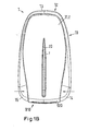
- the dispenser 1 comprises a dispenser housing 10, which has a housing front shell 11.1 (FIG. Fig. 1A ) and a housing rear shell 11.2 ( Fig. 1B ) and the two housing shells connecting and the dispenser on three narrow sides comprehensive, consisting of several parts housing part 12 which is formed in the lower region on each side as an actuating button 14, 15.
- the housing part is made of a composite material to ensure in that the part located on the one end face in the area 13 is rigid, while the two sides of the dispenser are designed to be movable on the narrow sides to execute a key movement towards the dispenser body (see arrows).
- the housing part can also be formed as a deformable hard shell, which can be pushed into the lower area, so that the actuating buttons are formed.
- an electronic display 16 and control buttons 17, 18 are provided in the front housing shell 11.1.
- the control over the intake of the tablets T is exercised by means of the electronic display.
- the operating buttons 14, 15 are used to select a menu item displayed by the display, for example for battery control or the day of use, the day of pause and the number of still in the cartridge tablets and to choose whether the tablet intake should be canceled.
- Fig. 1B the back of the dispenser 1 is shown.
- the rear side contains a window 20 which extends in the axial direction and allows the tablet T contained in the cartridge to be recognized.
- the housing rear shell 11.2 of the cartridge in the region of the window and the cartridge housing must be designed to be transparent at least in the part visible through the window.
- a part of the cartridge is to be seen, namely the cartridge lower shell 920, which rests flush on the housing of the dispenser.
- a discharge opening 922 for the tablets T can be seen ( Fig. 1 A) ,
- the cartridge ejection button 19, which is pushed in the direction of the arrow, is then inserted into the housing front plate 11.1 in order to eject the cartridge from the dispenser when it is empty.
- Fig. 2 is a part of the dispenser 1 (without skin) and a cartridge inserted into the dispenser 900 seen from the rear side.
- the cartridge is inserted into the dispenser from below (see arrow), wherein on the cartridge there is a separating device 910, part of which is the cartridge lower shell 920 and over which the cartridge rests against the dispenser housing in the lower area of the dispenser ( Fig. 1A ).
- the cartridge also includes a cartridge housing 930 in which the tablets T are located. This housing is formed by a cartridge front shell 933 and by a cartridge rear shell (not shown) which is preferred for use in the dispenser is made of a transparent material in order to be able to recognize the tablets through the window 20 on the back of the dispenser ( Fig. 1 B) ,
- the dispenser 1 contains inside a housing inner frame 100, which takes over substantially all static functions of the donor.
- the housing inner frame has, for example, a central web 110 (concealed), which is cylindrically curved from one side to accommodate the cartridge housing 930 (the front half of the cartridge housing is only partially visible).
- the concavity of this web forms together with other (not shown here) components of the donor a receiving shaft (indicated by reference numeral 150) into which the cartridge can be inserted from below into the dispenser.
- the receiving shaft is indicated here only by dashed lines and is characterized by an elongated cavity.
- Fig. 3 For example, the lower part of the housing inner frame 100 of the skin-removed dispenser 1 is shown as viewed from the front side.
- the separating device 910 of the cartridge in this case, without the lower shell 920 is shown. Therefore, a tablet slide 940 belonging to the separating device can be seen here, which slides in and is received by a slide holder 950 and which has a through opening 942 which also serves as a receptacle for tablets T to be dispensed. In a first position, this receiving compartment is aligned with the discharge opening of the lower shell, so that a tablet located in the receiving compartment can be dispensed to the outside.
- the receptacle When the tablet pusher has been moved to a second position (to the left as indicated by the arrow), the receptacle is flush with the reservoir space for the tablets formed by the cartridge housing 930 (not shown) so that a tablet can fall into the receptacle in this position.
- the receptacle is closed in this position by the cartridge lower shell 920 (not shown) down.
- the actuation buttons 14, 15 on the dispenser housing 10 are pressed to actuate the dispenser 1 inwards ( Fig. 1A ; see arrows). They act on two transport levers, a right transport lever 210 and a left transport lever 220. These two transport levers have racks 212 and 222 and are on these racks with a gear 230 in operative connection.
- the gear is mounted on the housing inner frame 100.
- the right transport lever is supported by a compression spring 240 on an abutment 102, so that this transport lever and thus also the left transport lever after pressing the operating button returns to the initial position, ie to a position in which both levers are extended outwards (first position).
- a boom 224 is further formed, which has a recess 226.
- a driving lug 944 is formed, which engages in this recess.
- the receiving compartment is moved into a position aligned with the storage space of the cartridge, so that a tablet falls from the storage space into the receiving compartment.
- the transport lever and thus also located in the slide tray are moved under spring force back to the right, so that the receiving tray again comes into alignment with the output opening position. This dispenses a tablet from the dispenser.
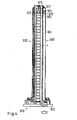
- Fig. 4 is a filled with tablets T cartridge 900 shown in section from the front.
- the cartridge has a separating device 910 with the cartridge lower shell 920 that can be seen here, and a cartridge housing 930 that consists of the cartridge front shell (not shown) and the cartridge rear shell 932.
- a cylindrical storage space is created in which the tablets are stacked.
- Between the two cartridge shells is on one side (right) an axially extending slot.
- the cartridge 900 may be handled separately in the form shown, i. be used to refill the dispenser 1 by the cartridge is inserted from the front side into the substantially cylindrical receiving shaft 150 in the dispenser and locked there.
- it is preferably sealed in a water-tight and airtight secondary packaging, for example in a bag or a blister.
- a tablet tab 960 which can basically move freely in the storage space of the cartridge in the axial direction ( Fig. 4A ).
- the tablet rider uses a rider arm 961 through the extending axially between the cartridge front shell 933 (not shown) and the cartridge rear shell 932. The tablet rider rests on the stack of pills.
- the axial movement of the tablet tab is limited by a tolerance compensation plug 970 upwards. This plug is inserted before filling the cartridge 900 with the tablets T in the pantry and pressed after filling the cartridge on the stack of tablets and the tablet tab.
- the tolerance compensation plug slides frictionally in the storage space, it is pressed onto the stack of tablets outside the dispenser during handling of the cartridge and holds the stack together, so that the individual tablets can not slip against each other or move against each other. This avoids, on the one hand, abrasion of the tablets and, on the other hand, that the tablets can also stand upright or at an angle during free movement. This prevents tilting and thus tilting of the tablets in the storage space.
- this has a base body 971 and two spring elements with locking lugs 972, 972 ', which bear against the inner wall of the cartridge housing.
- the inner wall in the areas in which the locking lugs are in contact with the inner wall opposite ratchet tracks 975, in which engage the locking lugs (see detailed illustration Fig. 4A ).
- These ratchet lanes are formed only on a length of about 2 cm, since the tolerance compensation plug should keep the tablets tightly packed only when fully filled cartridge, so that the plug must enter into the frictional connection with the inner wall of the cartridge housing only in the area in which only the fluctuation of the stack height resulting from the thickness tolerance of the individual tablets has to be compensated.
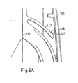
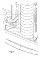
- Fig. 5 the donor 1 is shown without outer skin seen from the back, which contains a filled with tablets T cartridge 900.
- the cartridge contains the tablet rider 960 seated on the stack of tablets, which has a rider arm 961 protruding from the cartridge housing 930.
- the tolerance compensation plug 970 which includes the spring elements with locking lugs 972 (here one of the spring elements is shown).
- the latching noses of the spring elements engage in the ratchet tracks 975.
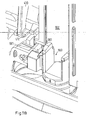
- the dispenser 1 also includes a feed handle 300 which engages around the central web 110 of the housing inner frame 100 and is movable along this web in the axial direction and guided thereon, for example by a dovetail guide, which passes through the side surfaces of the web and the U-shaped web. Leg 311, 312 of the bracket formed or by a locking of these U-legs with the side surfaces of the web ( Fig. 6 ).
- Fig. 6 the housing inner frame 100 is shown with the feed handle 300 from the back of the dispenser 1 from.
- the feed bracket has two arms 315, 316, which are formed at approximately at right angles to the U-legs 311, 312 thereto. At the ends of these booms are fastenings for the constant force springs 320, 330 at their respective one end.
- the constant force springs are fastened with their respective other ends in the lower part of the housing inner frame 100 and wound there. Thereby, a movement of the feed arm in the axial direction upwards can be achieved only against the spring force of the constant force springs.
- the constant force springs but also in corresponding brackets, for example, at the arms, be kept wound up on the feed yoke and the other ends are attached below the housing frame.
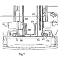
- a left locking lever 420 and a right locking lever 410 are provided for the cartridge.
- the locking levers are mounted on the housing inner frame 100 on pivot points 415, 425.
- At the respective lower ends of the locking lever locking lugs 412, 422 are provided ( Fig. 7 . 7A . 7B ). These engage in corresponding eyelets 981, 982 on the housing front shell 932 of the cartridge ( Fig. 7A . 7B ), when the lower legs of the locking lever and thus the locking lugs of the locking lever are tilted inwards ( Fig. 5 ; see inward arrows).
- This tilting movement is caused by the fact that the feed bar 300 upon insertion of the cartridge into the dispenser on the central web 110 of the housing inner frame is pushed upwards and then slides along the contact surfaces 416, 426 of the locking lever in the upper region and the locking lever thus presses apart.
- the upper legs of the locking lever to the outside and the lower legs are pivoted inwardly.
- spring arms 417, 427 which are integrally formed above the respective pivot points on the locking levers, snapped over corresponding press points 418, 428 behind associated projections 419, 429 on the housing inner frame, so that the locking lever are immovably held in this position ( Fig. 5A ).
- the locking lever are locked in place in the locking position after insertion of a filled cartridge, so that the cartridge can not be removed without further aids. This ensures that a cartridge after insertion and locking in the dispenser can not be removed again, provided that the cartridge is completely filled during insertion, since the feed handle is pushed up when pushing the filled cartridge up to the contact surfaces of the locking lever and this in transferred the locking position. This lock is maintained until the cartridge is completely empty.
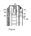
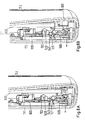
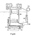
- an ejector mechanism which cancels the lock caused by the locking lever. Details of this ejection mechanism 'are in the 8A, 8B . 8C . 8D and 8E shown:
- a release lever 500 is provided, which is located immediately behind the ejection button 19 (hidden) ejector slide 600.
- the release lever is by means of a leg spring 510 ( Fig. 8C . 8D ) fixed in a substantially vertical position.
- the release lever is mounted via axles 520, 520 'on the housing front shell 11.1 in claws 121, 122, which are integrally formed on the housing front shell 11.1.
- the release lever is pivotable in the bearing of the claws (arrows in 8A, 8B . 8C . 8D ), but only against the spring force of the leg spring.
- the release lever 500 blocks the ejector slide 600 and thus the eject button 19 by locking lugs 531, 532 (or alternatively, only a single locking lug) in the rest position of the release lever in front of corresponding projections 611, 612 (alternatively only in front of a single projection) of the ejector slide and block the translatory movement of the slider downwards (ejection lock).
- Fig. 8C this is the of the ejector lever blocked ejector shown while the ejector in the presentation of Fig. 8D unlocked and already pushed down.
- the feed handle 300 in the dispenser 1 slides down ( Fig. 8B ).
- the feed handle engages the lever 540 of the release lever 500 and tilts the latter with the lower end against the spring force of the leg spring 510 forward ( Fig. 8B ; Arrow).
- the release lever releases the ejector slider 600 by moving the locking tabs 531, 532 away from the corresponding projections 611, 612 of the ejector slider.
- the function of the locking levers 410, 420 when unlocking the cartridge 900 is in Fig. 8E
- the lock of the cartridge is released by pushing the ejector slide 600 down by approx. 2 mm (arrow).
- the ejector comes with its contact surfaces 551, 552 with the lower legs of the locking lever 410, 420 in contact, so that they are pressed to the outside (arrows).
- the locking lugs 412, 422 of the locking lever are pressed outwards and moved out of the eyelets 981.982 of the cartridge. This will release the cartridge.
- the cartridge can now be ejected downwards.
- the locking lugs of the ejector slide simultaneously act as ejection tabs, since they attack at the edge of the top of the cartridge lower shell 920 and push them by the downward movement downward.
- the cartridge can then be grasped by hand and pulled out of the receiving shaft 150 of the dispenser 1.
- the ejector returns after pressing under spring force in the original position back.
- the leg spring 510 is used.
- the dispenser 1 has an electronic display 16 and two electronic control buttons 17, 18 ( Fig. 1 A) ,
- the electronic display serves to indicate the number of tablets T present in the cartridge 900 and the status of the tablet intake, ie whether the first administration phase of 24 days has already expired or not and, if the former is the case, the number of days that have already passed in the second flexible intake phase. Furthermore, it can be displayed if during the intake phase a tablet was not taken within a certain time window. In addition, the display can also show how many days have already elapsed in an event-free phase that may have been initiated. In addition, the ad can have a Show battery status. With the control buttons the transition to the capture-free phase and the selection of different menu items can be selected.
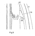
- the dispenser 1 contains batteries 1010, 1020 (FIG. Fig. 2 . 5 ) (alternatively, only a single battery), which should maintain the functionality of the dispenser 1 as long as possible, without having to be changed. Therefore, when a cartridge 900 is first inserted into the dispenser, the dispenser includes an initialization switch 710 disposed on the housing inner frame (FIG. Fig. 9 ). This switch is formed by a switch arm 430 of the left locking lever 420 at its upper leg. When inserting the cartridge this pushes the upper leg of the left locking lever to the outside, because the feed bar 300 slides on the stop surface 426 on the upper leg of this locking lever along and pushes the leg outward ( Fig. 5 ).
- the integrally formed on the left locking lever switch arm is pressed against the initialization switch and actuates it.
- the previously located in a rest position without energy consumption electronics is initialized and remains switched on by the special design of the initialization switch even after removing the cartridge.
- a second switch (not shown) next to the initialization switch 710 is actuated, which remains on only as long as the upper leg of the right latch is pushed outward, ie as long as the cartridge stays in the dispenser. After removing the cartridge, this second switch is turned off by the inward pivoting of the upper leg of the locking lever 420. This second switch gives the signal to the electronics that there is a cartridge in the dispenser.
- the number of tablets T present in the dispenser can be calculated in each case by the target specification that there is always a certain number of tablets T in a filled cartridge, for example 30 tablets, and by a further signal forwarded to the electronics, with which each withdrawal of a tablet from the donor is registered.
- the information reaches the electronics, that now again a completely filled cartridge is in the dispenser.
- the further signal with which a removal of a tablet T from the dispenser 1 is registered, is generated by a third switch (not shown), which is located in the region of a the transport lever 210, 220 is located and is switched on each actuation of the transport lever and thereby generates this further signal.
- the dispenser 1 includes a fourth switch (not shown) in the lower region of the receiving shaft 150, with which the sliding past the feed arm 300 registered and forwarded as an additional signal to the electronics.
- This fourth switch serves to signal the remaining number of tablets in the cartridge to the electronics shortly before the final emptying of the cartridge 900, for example, when there are only five tablets T in the cartridge. This is determined by the exact spatial positioning of this fourth switch on the receiving shaft, whereby the fourth switch is operated only when removing a tablet, if there are still a predetermined number of tablets in the cartridge. Namely, this control count may be necessary to properly indicate to the user how many tablets are still in the cartridge when there are only a few left.
Landscapes
- Health & Medical Sciences (AREA)
- Life Sciences & Earth Sciences (AREA)
- Animal Behavior & Ethology (AREA)
- General Health & Medical Sciences (AREA)
- Public Health (AREA)
- Veterinary Medicine (AREA)
- Engineering & Computer Science (AREA)
- Mechanical Engineering (AREA)
- Medical Informatics (AREA)
- Medical Preparation Storing Or Oral Administration Devices (AREA)
- Containers And Packaging Bodies Having A Special Means To Remove Contents (AREA)
- Medicinal Preparation (AREA)
- Infusion, Injection, And Reservoir Apparatuses (AREA)
Priority Applications (3)
| Application Number | Priority Date | Filing Date | Title |
|---|---|---|---|
| PL09759881T PL2370046T3 (pl) | 2008-11-26 | 2009-11-14 | Dozownik leku i jego zastosowanie |
| SI200931036T SI2370046T1 (sl) | 2008-11-26 | 2009-11-14 | Farmacevtski razdeljevalnik in njegova uporaba |
| CY20141100907T CY1115723T1 (el) | 2008-11-26 | 2014-11-03 | Διανεμητης φαρμακου και χρηση αυτου |
Applications Claiming Priority (2)
| Application Number | Priority Date | Filing Date | Title |
|---|---|---|---|
| DE102008059676A DE102008059676A1 (de) | 2008-11-26 | 2008-11-26 | Arzneimittelspender und dessen Verwendung |
| PCT/EP2009/008124 WO2010060547A1 (de) | 2008-11-26 | 2009-11-14 | Arzneimittelspender und dessen verwendung |
Publications (2)
| Publication Number | Publication Date |
|---|---|
| EP2370046A1 EP2370046A1 (de) | 2011-10-05 |
| EP2370046B1 true EP2370046B1 (de) | 2014-08-06 |
Family
ID=42027599
Family Applications (1)
| Application Number | Title | Priority Date | Filing Date |
|---|---|---|---|
| EP09759881.7A Active EP2370046B1 (de) | 2008-11-26 | 2009-11-14 | Arzneimittelspender und dessen Verwendung |
Country Status (37)
| Country | Link |
|---|---|
| US (1) | US20110290818A1 (pl) |
| EP (1) | EP2370046B1 (pl) |
| JP (1) | JP5749173B2 (pl) |
| KR (1) | KR101685717B1 (pl) |
| CN (1) | CN102227202B (pl) |
| AR (1) | AR074407A1 (pl) |
| AU (1) | AU2009319436B2 (pl) |
| BR (1) | BRPI0921225A2 (pl) |
| CA (1) | CA2744372C (pl) |
| CO (1) | CO6361886A2 (pl) |
| CR (1) | CR20110276A (pl) |
| CU (1) | CU24118B1 (pl) |
| CY (1) | CY1115723T1 (pl) |
| DE (1) | DE102008059676A1 (pl) |
| DK (1) | DK2370046T3 (pl) |
| DO (1) | DOP2011000158A (pl) |
| EA (1) | EA020809B1 (pl) |
| EC (1) | ECSP11011087A (pl) |
| ES (1) | ES2513830T3 (pl) |
| HN (1) | HN2011001409A (pl) |
| HR (1) | HRP20141072T1 (pl) |
| IL (1) | IL212409A (pl) |
| MA (1) | MA32831B1 (pl) |
| MX (1) | MX2011005600A (pl) |
| MY (1) | MY154062A (pl) |
| NZ (1) | NZ593016A (pl) |
| PA (1) | PA8850701A1 (pl) |
| PE (1) | PE20120377A1 (pl) |
| PL (1) | PL2370046T3 (pl) |
| PT (1) | PT2370046E (pl) |
| SI (1) | SI2370046T1 (pl) |
| TN (1) | TN2011000270A1 (pl) |
| TW (1) | TWI477267B (pl) |
| UA (1) | UA106359C2 (pl) |
| UY (1) | UY32270A (pl) |
| WO (1) | WO2010060547A1 (pl) |
| ZA (1) | ZA201104710B (pl) |
Families Citing this family (6)
| Publication number | Priority date | Publication date | Assignee | Title |
|---|---|---|---|---|
| DE102008059673A1 (de) | 2008-11-26 | 2010-05-27 | Bayer Schering Pharma Aktiengesellschaft | Kartusche, ein die Kartusche enthaltender Arzneimittelspender sowie Verwendungen der Kartusche und des Arzneimittelspenders |
| CN116863598B (zh) | 2017-10-13 | 2025-09-02 | 快而安有限责任公司 | 用于自动包装机的通用供给机构 |
| FR3088625B1 (fr) * | 2018-11-20 | 2020-12-18 | Stiplastics | Dispositif securise de comptage et de distribution d’objets |
| US11577905B2 (en) | 2020-03-11 | 2023-02-14 | Becton Dickinson Rowa Germany Gmbh | Storage and dispensing station for drugs |
| EP3879503A1 (de) * | 2020-03-11 | 2021-09-15 | Becton Dickinson Rowa Germany GmbH | Vorrats- und abgabestation für arzneimittel |
| CN114788782B (zh) * | 2021-12-30 | 2024-07-23 | 席万凤 | 一种快速弹出药丸的便携药盒 |
Family Cites Families (29)
| Publication number | Priority date | Publication date | Assignee | Title |
|---|---|---|---|---|
| US2567089A (en) * | 1949-09-01 | 1951-09-04 | Thomas P Walsh | Dispenser |
| US2683554A (en) * | 1951-04-21 | 1954-07-13 | Jr George C Mulhauser | Pill dispenser |
| US2960259A (en) * | 1956-06-25 | 1960-11-15 | James A Mcintosh | Dispenser for pills or pellets and the like |
| US3143207A (en) | 1962-07-27 | 1964-08-04 | David P Wagner | Medication dispensing means |
| US3270915A (en) * | 1965-02-03 | 1966-09-06 | Searle & Co | Dispensing means for pharmaceutical tablets |
| DE3143953A1 (de) * | 1981-11-05 | 1983-05-11 | Henkel KGaA, 4000 Düsseldorf | "dosierspender fuer tablettenfoermige produkte" |
| JPH0531113Y2 (pl) * | 1986-05-30 | 1993-08-10 | ||
| AT391300B (de) * | 1989-04-12 | 1990-09-10 | Hinterreiter Ignaz | Tablettenspender |
| AT392451B (de) | 1989-11-16 | 1991-04-10 | Hinterreiter Ignaz | Tablettenspender |
| JPH084458Y2 (ja) * | 1990-04-26 | 1996-02-07 | ぺんてる株式会社 | 粒体吐出容器、粒体収容体、及び、粒体集合体 |
| KR100194160B1 (ko) | 1990-04-26 | 1999-06-15 | 아사베 히로시 | 정제등의 분립체 토출용기 |
| US5048720A (en) | 1990-09-17 | 1991-09-17 | Tca Group, Inc. | Tablet dispenser |
| TW223015B (pl) * | 1992-07-01 | 1994-05-01 | Duphar Int Res | |
| DE4230452C2 (de) * | 1992-09-11 | 1996-06-05 | Fraunhofer Ges Forschung | Behältnis zur Aufbewahrung und Einzelausgabe von Dragees, die in vorgegebenen Zyklen anzuwenden sind |
| JPH0837820A (ja) * | 1994-07-28 | 1996-02-13 | Sakata No Tane:Kk | 種まき器 |
| WO1998023164A1 (en) * | 1996-11-29 | 1998-06-04 | Unilever Plc | Black leaf tea |
| EP0891973B1 (en) * | 1997-07-15 | 2001-10-17 | Unilever Plc | Improvements in or relating to producing theaflavin |
| ATE233054T1 (de) * | 1998-08-17 | 2003-03-15 | Unilever Nv | Behandlung von tee mit kohlendioxid |
| DE69924036T2 (de) | 1999-04-28 | 2006-02-09 | Telum Ab | Tablettenspender |
| US6409020B1 (en) | 1999-08-09 | 2002-06-25 | Pfizer Inc. | Child-resistant blister package |
| GB0010315D0 (en) * | 2000-04-27 | 2000-06-14 | Unilever Plc | Black tea manufacture |
| AT409366B (de) | 2000-06-20 | 2002-07-25 | Haas Beteiligungsgesellschaft | Magazin zur aufnahme und vereinzelten abgabe von tabletten |
| US6581797B2 (en) * | 2001-06-15 | 2003-06-24 | Sharper Image Corporation | Pill dispenser with reminder |
| GB0321779D0 (en) * | 2003-09-17 | 2003-10-15 | Cope Allman Plastic Packaging | Pill dispensers |
| US7360669B2 (en) * | 2005-11-22 | 2008-04-22 | Cornell Drajan | Dispenser for spherical articles |
| US7543579B2 (en) * | 2006-09-05 | 2009-06-09 | Shiow-Ching Chang | Apparatus for loading and unloading pellets in a slingshot |
| MX2010011103A (es) * | 2008-04-09 | 2010-11-01 | Merck Serono Sa | Recipiente de medicacion a prueba de niños. |
| US9016516B2 (en) * | 2010-05-10 | 2015-04-28 | Mallinckrodt Llc | Pen-type pharmaceutical product dispenser |
| TW201144204A (en) * | 2010-06-04 | 2011-12-16 | Taidoc Technology Corp | Ear cup supply device and ear cup and ear cup set |
-
2008
- 2008-11-26 DE DE102008059676A patent/DE102008059676A1/de not_active Ceased
-
2009
- 2009-11-14 PL PL09759881T patent/PL2370046T3/pl unknown
- 2009-11-14 AU AU2009319436A patent/AU2009319436B2/en not_active Ceased
- 2009-11-14 MY MYPI2011001948A patent/MY154062A/en unknown
- 2009-11-14 PE PE2011001100A patent/PE20120377A1/es not_active Application Discontinuation
- 2009-11-14 CU CUP2011000117A patent/CU24118B1/es active IP Right Grant
- 2009-11-14 KR KR1020117011888A patent/KR101685717B1/ko not_active Expired - Fee Related
- 2009-11-14 JP JP2011537870A patent/JP5749173B2/ja not_active Expired - Fee Related
- 2009-11-14 NZ NZ593016A patent/NZ593016A/xx not_active IP Right Cessation
- 2009-11-14 CN CN200980147553.7A patent/CN102227202B/zh not_active Expired - Fee Related
- 2009-11-14 MX MX2011005600A patent/MX2011005600A/es active IP Right Grant
- 2009-11-14 UA UAA201107744A patent/UA106359C2/uk unknown
- 2009-11-14 EP EP09759881.7A patent/EP2370046B1/de active Active
- 2009-11-14 PT PT97598817T patent/PT2370046E/pt unknown
- 2009-11-14 HR HRP20141072AT patent/HRP20141072T1/hr unknown
- 2009-11-14 BR BRPI0921225A patent/BRPI0921225A2/pt not_active Application Discontinuation
- 2009-11-14 WO PCT/EP2009/008124 patent/WO2010060547A1/de not_active Ceased
- 2009-11-14 EA EA201100792A patent/EA020809B1/ru not_active IP Right Cessation
- 2009-11-14 CA CA2744372A patent/CA2744372C/en not_active Expired - Fee Related
- 2009-11-14 DK DK09759881.7T patent/DK2370046T3/da active
- 2009-11-14 ES ES09759881.7T patent/ES2513830T3/es active Active
- 2009-11-14 US US13/131,246 patent/US20110290818A1/en not_active Abandoned
- 2009-11-14 SI SI200931036T patent/SI2370046T1/sl unknown
- 2009-11-25 TW TW098140140A patent/TWI477267B/zh not_active IP Right Cessation
- 2009-11-26 PA PA8850701A patent/PA8850701A1/es unknown
- 2009-11-26 AR ARP090104562 patent/AR074407A1/es not_active Application Discontinuation
- 2009-11-26 UY UY32270A patent/UY32270A/es not_active Application Discontinuation
-
2011
- 2011-04-17 IL IL212409A patent/IL212409A/en not_active IP Right Cessation
- 2011-05-24 TN TN2011000270A patent/TN2011000270A1/fr unknown
- 2011-05-26 DO DO2011000158A patent/DOP2011000158A/es unknown
- 2011-05-26 HN HN2011001409A patent/HN2011001409A/es unknown
- 2011-05-26 CR CR20110276A patent/CR20110276A/es unknown
- 2011-05-26 CO CO11065461A patent/CO6361886A2/es active IP Right Grant
- 2011-05-26 EC ECSP11011087 patent/ECSP11011087A/es unknown
- 2011-05-26 MA MA33892A patent/MA32831B1/fr unknown
- 2011-06-24 ZA ZA2011/04710A patent/ZA201104710B/en unknown
-
2014
- 2014-11-03 CY CY20141100907T patent/CY1115723T1/el unknown
Also Published As
Similar Documents
| Publication | Publication Date | Title |
|---|---|---|
| EP2370045B1 (de) | Kartusche, arzneimittelspender für feststoff-arzneimittelportionen sowie verwendungen der kartusche und des arzneimittelspenders | |
| EP2370327B1 (de) | Kartusche, ein die kartusche enthaltender arzneimittelspender sowie verwendungen der kartusche und des arzneimittelspenders | |
| EP2370046B1 (de) | Arzneimittelspender und dessen Verwendung | |
| EP1751032A2 (de) | Spendervorrichtung, produktträger sowie packungseinheit aus produktträger und spendervorrichtung | |
| DE102008059674A1 (de) | Kartusche für einen Arzneimittelspender und deren Verwendung | |
| DE102008059675A1 (de) | Arzneimittelspender und dessen Verwendung | |
| DE102008059672A1 (de) | Kartusche, ein die Kartusche enthaltender Arzneimittelspender sowie Verwendungen der Kartusche und des Arzneimittelspenders |
Legal Events
| Date | Code | Title | Description |
|---|---|---|---|
| PUAI | Public reference made under article 153(3) epc to a published international application that has entered the european phase |
Free format text: ORIGINAL CODE: 0009012 |
|
| 17P | Request for examination filed |
Effective date: 20110627 |
|
| AK | Designated contracting states |
Kind code of ref document: A1 Designated state(s): AT BE BG CH CY CZ DE DK EE ES FI FR GB GR HR HU IE IS IT LI LT LU LV MC MK MT NL NO PL PT RO SE SI SK SM TR |
|
| AX | Request for extension of the european patent |
Extension state: AL BA RS |
|
| RAP1 | Party data changed (applicant data changed or rights of an application transferred) |
Owner name: BAYER INTELLECTUAL PROPERTY GMBH |
|
| 17Q | First examination report despatched |
Effective date: 20130205 |
|
| GRAP | Despatch of communication of intention to grant a patent |
Free format text: ORIGINAL CODE: EPIDOSNIGR1 |
|
| INTG | Intention to grant announced |
Effective date: 20140106 |
|
| GRAP | Despatch of communication of intention to grant a patent |
Free format text: ORIGINAL CODE: EPIDOSNIGR1 |
|
| INTG | Intention to grant announced |
Effective date: 20140519 |
|
| GRAS | Grant fee paid |
Free format text: ORIGINAL CODE: EPIDOSNIGR3 |
|
| GRAA | (expected) grant |
Free format text: ORIGINAL CODE: 0009210 |
|
| AK | Designated contracting states |
Kind code of ref document: B1 Designated state(s): AT BE BG CH CY CZ DE DK EE ES FI FR GB GR HR HU IE IS IT LI LT LU LV MC MK MT NL NO PL PT RO SE SI SK SM TR |
|
| AX | Request for extension of the european patent |
Extension state: AL BA RS |
|
| REG | Reference to a national code |
Ref country code: GB Ref legal event code: FG4D Free format text: NOT ENGLISH |
|
| REG | Reference to a national code |
Ref country code: AT Ref legal event code: REF Ref document number: 680650 Country of ref document: AT Kind code of ref document: T Effective date: 20140815 Ref country code: CH Ref legal event code: EP |
|
| REG | Reference to a national code |
Ref country code: IE Ref legal event code: FG4D Free format text: LANGUAGE OF EP DOCUMENT: GERMAN |
|
| REG | Reference to a national code |
Ref country code: DE Ref legal event code: R096 Ref document number: 502009009765 Country of ref document: DE Effective date: 20140918 |
|
| REG | Reference to a national code |
Ref country code: ES Ref legal event code: FG2A Ref document number: 2513830 Country of ref document: ES Kind code of ref document: T3 Effective date: 20141027 Ref country code: RO Ref legal event code: EPE |
|
| REG | Reference to a national code |
Ref country code: PT Ref legal event code: SC4A Free format text: AVAILABILITY OF NATIONAL TRANSLATION Effective date: 20141024 |
|
| REG | Reference to a national code |
Ref country code: HR Ref legal event code: TUEP Ref document number: P20141072 Country of ref document: HR |
|
| REG | Reference to a national code |
Ref country code: DK Ref legal event code: T3 Effective date: 20141105 |
|
| REG | Reference to a national code |
Ref country code: SE Ref legal event code: TRGR |
|
| REG | Reference to a national code |
Ref country code: NL Ref legal event code: T3 |
|
| REG | Reference to a national code |
Ref country code: EE Ref legal event code: FG4A Ref document number: E009624 Country of ref document: EE Effective date: 20141013 |
|
| REG | Reference to a national code |
Ref country code: HR Ref legal event code: T1PR Ref document number: P20141072 Country of ref document: HR |
|
| REG | Reference to a national code |
Ref country code: NO Ref legal event code: T2 Effective date: 20140806 |
|
| REG | Reference to a national code |
Ref country code: PL Ref legal event code: T3 |
|
| REG | Reference to a national code |
Ref country code: SK Ref legal event code: T3 Ref document number: E 17314 Country of ref document: SK |
|
| REG | Reference to a national code |
Ref country code: GR Ref legal event code: EP Ref document number: 20140402234 Country of ref document: GR Effective date: 20141223 |
|
| RIN2 | Information on inventor provided after grant (corrected) |
Inventor name: REINHOLD, TOM, S. Inventor name: LEIFELD, SABINE Inventor name: GRUETZMACHER, HEIKE Inventor name: LEZZAIQ, SAMER |
|
| REG | Reference to a national code |
Ref country code: DE Ref legal event code: R097 Ref document number: 502009009765 Country of ref document: DE |
|
| PLBE | No opposition filed within time limit |
Free format text: ORIGINAL CODE: 0009261 |
|
| STAA | Information on the status of an ep patent application or granted ep patent |
Free format text: STATUS: NO OPPOSITION FILED WITHIN TIME LIMIT |
|
| 26N | No opposition filed |
Effective date: 20150507 |
|
| REG | Reference to a national code |
Ref country code: HU Ref legal event code: AG4A Ref document number: E023785 Country of ref document: HU |
|
| REG | Reference to a national code |
Ref country code: FR Ref legal event code: PLFP Year of fee payment: 7 |
|
| PG25 | Lapsed in a contracting state [announced via postgrant information from national office to epo] |
Ref country code: SM Free format text: LAPSE BECAUSE OF FAILURE TO SUBMIT A TRANSLATION OF THE DESCRIPTION OR TO PAY THE FEE WITHIN THE PRESCRIBED TIME-LIMIT Effective date: 20140806 |
|
| REG | Reference to a national code |
Ref country code: FR Ref legal event code: PLFP Year of fee payment: 8 |
|
| REG | Reference to a national code |
Ref country code: HR Ref legal event code: ODRP Ref document number: P20141072 Country of ref document: HR Payment date: 20171026 Year of fee payment: 9 Ref country code: FR Ref legal event code: PLFP Year of fee payment: 9 |
|
| PGFP | Annual fee paid to national office [announced via postgrant information from national office to epo] |
Ref country code: LU Payment date: 20171024 Year of fee payment: 9 |
|
| PGFP | Annual fee paid to national office [announced via postgrant information from national office to epo] |
Ref country code: SK Payment date: 20171030 Year of fee payment: 9 Ref country code: DK Payment date: 20171110 Year of fee payment: 9 Ref country code: LT Payment date: 20171113 Year of fee payment: 9 Ref country code: RO Payment date: 20171027 Year of fee payment: 9 Ref country code: TR Payment date: 20171110 Year of fee payment: 9 Ref country code: FR Payment date: 20171026 Year of fee payment: 9 Ref country code: NL Payment date: 20171115 Year of fee payment: 9 Ref country code: NO Payment date: 20171109 Year of fee payment: 9 Ref country code: EE Payment date: 20171029 Year of fee payment: 9 Ref country code: CZ Payment date: 20171025 Year of fee payment: 9 Ref country code: MC Payment date: 20171129 Year of fee payment: 9 Ref country code: HU Payment date: 20171107 Year of fee payment: 9 Ref country code: FI Payment date: 20171109 Year of fee payment: 9 |
|
| PGFP | Annual fee paid to national office [announced via postgrant information from national office to epo] |
Ref country code: GR Payment date: 20171025 Year of fee payment: 9 Ref country code: PL Payment date: 20171106 Year of fee payment: 9 Ref country code: LV Payment date: 20171108 Year of fee payment: 9 Ref country code: BG Payment date: 20171027 Year of fee payment: 9 Ref country code: IT Payment date: 20171123 Year of fee payment: 9 Ref country code: HR Payment date: 20171026 Year of fee payment: 9 Ref country code: BE Payment date: 20171024 Year of fee payment: 9 Ref country code: CH Payment date: 20171114 Year of fee payment: 9 Ref country code: GB Payment date: 20171108 Year of fee payment: 9 Ref country code: SI Payment date: 20171027 Year of fee payment: 9 Ref country code: SE Payment date: 20171113 Year of fee payment: 9 Ref country code: PT Payment date: 20171113 Year of fee payment: 9 Ref country code: ES Payment date: 20171201 Year of fee payment: 9 Ref country code: IS Payment date: 20171030 Year of fee payment: 9 Ref country code: AT Payment date: 20171026 Year of fee payment: 9 Ref country code: IE Payment date: 20171109 Year of fee payment: 9 |
|
| PGFP | Annual fee paid to national office [announced via postgrant information from national office to epo] |
Ref country code: CY Payment date: 20171109 Year of fee payment: 9 |
|
| PGFP | Annual fee paid to national office [announced via postgrant information from national office to epo] |
Ref country code: MK Payment date: 20171025 Year of fee payment: 9 |
|
| PGFP | Annual fee paid to national office [announced via postgrant information from national office to epo] |
Ref country code: MT Payment date: 20171115 Year of fee payment: 9 |
|
| REG | Reference to a national code |
Ref country code: HR Ref legal event code: PBON Ref document number: P20141072 Country of ref document: HR Effective date: 20181114 |
|
| REG | Reference to a national code |
Ref country code: LT Ref legal event code: MM4D Effective date: 20181114 |
|
| REG | Reference to a national code |
Ref country code: EE Ref legal event code: MM4A Ref document number: E009624 Country of ref document: EE Effective date: 20181130 |
|
| REG | Reference to a national code |
Ref country code: DK Ref legal event code: EBP Effective date: 20181130 Ref country code: NO Ref legal event code: MMEP |
|
| REG | Reference to a national code |
Ref country code: CH Ref legal event code: PL |
|
| REG | Reference to a national code |
Ref country code: SE Ref legal event code: EUG |
|
| REG | Reference to a national code |
Ref country code: NL Ref legal event code: MM Effective date: 20181201 |
|
| REG | Reference to a national code |
Ref country code: AT Ref legal event code: MM01 Ref document number: 680650 Country of ref document: AT Kind code of ref document: T Effective date: 20181114 |
|
| GBPC | Gb: european patent ceased through non-payment of renewal fee |
Effective date: 20181114 |
|
| PG25 | Lapsed in a contracting state [announced via postgrant information from national office to epo] |
Ref country code: PT Free format text: LAPSE BECAUSE OF NON-PAYMENT OF DUE FEES Effective date: 20190514 Ref country code: CZ Free format text: LAPSE BECAUSE OF NON-PAYMENT OF DUE FEES Effective date: 20181114 Ref country code: LT Free format text: LAPSE BECAUSE OF NON-PAYMENT OF DUE FEES Effective date: 20181114 Ref country code: CY Free format text: LAPSE BECAUSE OF NON-PAYMENT OF DUE FEES Effective date: 20181114 Ref country code: LU Free format text: LAPSE BECAUSE OF NON-PAYMENT OF DUE FEES Effective date: 20181114 Ref country code: NO Free format text: LAPSE BECAUSE OF NON-PAYMENT OF DUE FEES Effective date: 20181130 Ref country code: FI Free format text: LAPSE BECAUSE OF NON-PAYMENT OF DUE FEES Effective date: 20181114 Ref country code: MC Free format text: LAPSE BECAUSE OF NON-PAYMENT OF DUE FEES Effective date: 20181130 Ref country code: SE Free format text: LAPSE BECAUSE OF NON-PAYMENT OF DUE FEES Effective date: 20181115 |
|
| REG | Reference to a national code |
Ref country code: SK Ref legal event code: MM4A Ref document number: E 17314 Country of ref document: SK Effective date: 20181114 |
|
| REG | Reference to a national code |
Ref country code: BE Ref legal event code: MM Effective date: 20181130 |
|
| REG | Reference to a national code |
Ref country code: IE Ref legal event code: MM4A |
|
| PG25 | Lapsed in a contracting state [announced via postgrant information from national office to epo] |
Ref country code: CH Free format text: LAPSE BECAUSE OF NON-PAYMENT OF DUE FEES Effective date: 20181130 Ref country code: SI Free format text: LAPSE BECAUSE OF NON-PAYMENT OF DUE FEES Effective date: 20181115 Ref country code: BG Free format text: LAPSE BECAUSE OF NON-PAYMENT OF DUE FEES Effective date: 20190531 Ref country code: IS Free format text: LAPSE BECAUSE OF FAILURE TO SUBMIT A TRANSLATION OF THE DESCRIPTION OR TO PAY THE FEE WITHIN THE PRESCRIBED TIME-LIMIT Effective date: 20190531 Ref country code: HR Free format text: LAPSE BECAUSE OF NON-PAYMENT OF DUE FEES Effective date: 20181114 Ref country code: SK Free format text: LAPSE BECAUSE OF NON-PAYMENT OF DUE FEES Effective date: 20181114 Ref country code: NL Free format text: LAPSE BECAUSE OF NON-PAYMENT OF DUE FEES Effective date: 20181201 Ref country code: LI Free format text: LAPSE BECAUSE OF NON-PAYMENT OF DUE FEES Effective date: 20181130 Ref country code: GR Free format text: LAPSE BECAUSE OF NON-PAYMENT OF DUE FEES Effective date: 20190605 Ref country code: EE Free format text: LAPSE BECAUSE OF NON-PAYMENT OF DUE FEES Effective date: 20181130 Ref country code: HU Free format text: LAPSE BECAUSE OF NON-PAYMENT OF DUE FEES Effective date: 20181115 Ref country code: LV Free format text: LAPSE BECAUSE OF NON-PAYMENT OF DUE FEES Effective date: 20181114 Ref country code: RO Free format text: LAPSE BECAUSE OF NON-PAYMENT OF DUE FEES Effective date: 20181114 |
|
| REG | Reference to a national code |
Ref country code: SI Ref legal event code: KO00 Effective date: 20190709 |
|
| PG25 | Lapsed in a contracting state [announced via postgrant information from national office to epo] |
Ref country code: IE Free format text: LAPSE BECAUSE OF NON-PAYMENT OF DUE FEES Effective date: 20181114 Ref country code: IT Free format text: LAPSE BECAUSE OF NON-PAYMENT OF DUE FEES Effective date: 20181114 Ref country code: AT Free format text: LAPSE BECAUSE OF NON-PAYMENT OF DUE FEES Effective date: 20181114 Ref country code: DK Free format text: LAPSE BECAUSE OF NON-PAYMENT OF DUE FEES Effective date: 20181130 Ref country code: FR Free format text: LAPSE BECAUSE OF NON-PAYMENT OF DUE FEES Effective date: 20181130 |
|
| PG25 | Lapsed in a contracting state [announced via postgrant information from national office to epo] |
Ref country code: BE Free format text: LAPSE BECAUSE OF NON-PAYMENT OF DUE FEES Effective date: 20181130 |
|
| PG25 | Lapsed in a contracting state [announced via postgrant information from national office to epo] |
Ref country code: GB Free format text: LAPSE BECAUSE OF NON-PAYMENT OF DUE FEES Effective date: 20181114 |
|
| REG | Reference to a national code |
Ref country code: ES Ref legal event code: FD2A Effective date: 20200103 |
|
| PGFP | Annual fee paid to national office [announced via postgrant information from national office to epo] |
Ref country code: DE Payment date: 20191029 Year of fee payment: 11 |
|
| PG25 | Lapsed in a contracting state [announced via postgrant information from national office to epo] |
Ref country code: ES Free format text: LAPSE BECAUSE OF NON-PAYMENT OF DUE FEES Effective date: 20181115 |
|
| PG25 | Lapsed in a contracting state [announced via postgrant information from national office to epo] |
Ref country code: PL Free format text: LAPSE BECAUSE OF NON-PAYMENT OF DUE FEES Effective date: 20181114 |
|
| PG25 | Lapsed in a contracting state [announced via postgrant information from national office to epo] |
Ref country code: MT Free format text: LAPSE BECAUSE OF NON-PAYMENT OF DUE FEES Effective date: 20181114 |
|
| REG | Reference to a national code |
Ref country code: DE Ref legal event code: R119 Ref document number: 502009009765 Country of ref document: DE |
|
| PG25 | Lapsed in a contracting state [announced via postgrant information from national office to epo] |
Ref country code: DE Free format text: LAPSE BECAUSE OF NON-PAYMENT OF DUE FEES Effective date: 20210601 |
|
| PG25 | Lapsed in a contracting state [announced via postgrant information from national office to epo] |
Ref country code: TR Free format text: LAPSE BECAUSE OF NON-PAYMENT OF DUE FEES Effective date: 20181114 |