EP2369228B1 - Energy recovery unit - Google Patents
Energy recovery unit Download PDFInfo
- Publication number
- EP2369228B1 EP2369228B1 EP11154086.0A EP11154086A EP2369228B1 EP 2369228 B1 EP2369228 B1 EP 2369228B1 EP 11154086 A EP11154086 A EP 11154086A EP 2369228 B1 EP2369228 B1 EP 2369228B1
- Authority
- EP
- European Patent Office
- Prior art keywords
- condensate
- recovery unit
- energy recovery
- flash
- feed line
- Prior art date
- Legal status (The legal status is an assumption and is not a legal conclusion. Google has not performed a legal analysis and makes no representation as to the accuracy of the status listed.)
- Active
Links
Images
Classifications
-
- F—MECHANICAL ENGINEERING; LIGHTING; HEATING; WEAPONS; BLASTING
- F22—STEAM GENERATION
- F22D—PREHEATING, OR ACCUMULATING PREHEATED, FEED-WATER FOR STEAM GENERATION; FEED-WATER SUPPLY FOR STEAM GENERATION; CONTROLLING WATER LEVEL FOR STEAM GENERATION; AUXILIARY DEVICES FOR PROMOTING WATER CIRCULATION WITHIN STEAM BOILERS
- F22D1/00—Feed-water heaters, i.e. economisers or like preheaters
- F22D1/32—Feed-water heaters, i.e. economisers or like preheaters arranged to be heated by steam, e.g. bled from turbines
- F22D1/325—Schematic arrangements or control devices therefor
-
- F—MECHANICAL ENGINEERING; LIGHTING; HEATING; WEAPONS; BLASTING
- F22—STEAM GENERATION
- F22B—METHODS OF STEAM GENERATION; STEAM BOILERS
- F22B3/00—Other methods of steam generation; Steam boilers not provided for in other groups of this subclass
- F22B3/04—Other methods of steam generation; Steam boilers not provided for in other groups of this subclass by drop in pressure of high-pressure hot water within pressure- reducing chambers, e.g. in accumulators
-
- F—MECHANICAL ENGINEERING; LIGHTING; HEATING; WEAPONS; BLASTING
- F22—STEAM GENERATION
- F22D—PREHEATING, OR ACCUMULATING PREHEATED, FEED-WATER FOR STEAM GENERATION; FEED-WATER SUPPLY FOR STEAM GENERATION; CONTROLLING WATER LEVEL FOR STEAM GENERATION; AUXILIARY DEVICES FOR PROMOTING WATER CIRCULATION WITHIN STEAM BOILERS
- F22D1/00—Feed-water heaters, i.e. economisers or like preheaters
- F22D1/16—Feed-water heaters, i.e. economisers or like preheaters with water tubes arranged otherwise than in the boiler furnace, fire tubes, or flue ways
-
- F—MECHANICAL ENGINEERING; LIGHTING; HEATING; WEAPONS; BLASTING
- F22—STEAM GENERATION
- F22D—PREHEATING, OR ACCUMULATING PREHEATED, FEED-WATER FOR STEAM GENERATION; FEED-WATER SUPPLY FOR STEAM GENERATION; CONTROLLING WATER LEVEL FOR STEAM GENERATION; AUXILIARY DEVICES FOR PROMOTING WATER CIRCULATION WITHIN STEAM BOILERS
- F22D1/00—Feed-water heaters, i.e. economisers or like preheaters
- F22D1/32—Feed-water heaters, i.e. economisers or like preheaters arranged to be heated by steam, e.g. bled from turbines
Definitions
- the present invention relates to an energy recovery unit which is particularly, although not exclusively, suited for recovering thermal energy from condensate from an industrial process utilising steam as a heating medium.
- steam is generated in a boiler and transferred through pipework at high temperature and pressure to various industrial processes where the energy in the steam is utilised.
- condensate can form, and it is common for this condensate to be collected at a lower part of the system and periodically removed by means of steam traps. It is common practice for steam traps to discharge to atmospheric pressure.
- the condensate is liquid water under the high pressure prevailing within the system, its temperature may be above 100°C and so it will turn to flash steam when vented to atmospheric pressure. The heat in the condensate is thus lost. This not only represents a waste of energy, but can also incur financial penalties under measures implemented to reduce usage of carbon fuels.
- WO 97/34107 discloses a heat recovery system has with a first tube bundle for circulating a first fluid, a second tube bundle for circulating a second fluid, and a shell which accommodates the tube bundles arranged in the shell, so that when a third fluid is circulated through the shell it contacts the tube bundles for a heat transfer between the third fluid and the two first-mentioned fluids, to provide a heat transfer between three fluids.
- US 1,790,306 discloses a water heater and steam condenser comprising a U-shaped casing formed from a pair of tubular portions arranged in parallel, a tubular element for connecting the portions together, and a coil disposed within each of the portions and being operatively connected.
- EP 0 192 918 discloses a heater comprising two separate tube nests of which one heats the circulating water by condensation and supercooling and the other heats a partial flow of this water by the desuperheating of steam. Steam is admitted through pipe. The foregoing partial flow of water comes from the desuperheating zone of a heater located downstream and is admitted through a manifold. Pipes are wound round a central drum.
- DE 10 78 138 discloses a steam-heated, horizontal surface heat exchanger for feed water or other coolant comprising an annular arrangement of U-tubes and a built-in condensate cooler.
- US 4,393,816 discloses a thermodynamic method is for improving the quality of wet steam produced by conventional and once through type boilers. Moisture entrained with such steam is first separated in a steam-water separation vessel. The separated moisture is thereafter vaporized by pressure reduction and flashed to form lower pressure steam and condensate containing dissolved solids. The condensate is utilized to preheat fresh boiler feedwater. The lower pressure steam is condensed and supplements the boiler feedwater to form a hotter combined net feedwater stream containing reduced quantities of dissolved solids. It is known to use hot condensate, and steam derived from the condensate, to pre-heat boiler feed water.
- an energy recovery unit comprising: a vessel having a condensate inlet and a condensate outlet; a fluid feed line defining a fluid path; and first and second heat exchangers located within the vessel and arranged to transfer heat from flash vapour and condensate respectively, to fluid in the fluid feed line.
- the first heat exchanger may be located above the second heat exchanger in the vessel.
- the first and/or second heat exchanger may comprise a plurality of heat transfer fins in thermal contact with the fluid feed line.
- the plurality of fins may be stacked horizontally.
- the condensate inlet may be arranged to direct condensate towards the second heat exchanger.
- the condensate outlet is located towards the bottom of the vessel.
- the condensate outlet may be one of two or more condensate outlets disposed at different levels in the vessel.
- a condensate outlet pipe may connect the or each condensate outlet to a steam trap.
- the energy recovery unit may further comprise a flash vapour outlet.
- the flash vapour outlet may be located towards the top of the vessel.
- a flash vapour outlet pipe may connect the flash vapour outlet to a pressure control valve.
- the fluid feed line passes through the vessel and the fluid feed path passes through the first and the second heat exchangers.
- the fluid feed line may be a boiler feed line.
- a steam utilisation system including a condensate energy recovery unit in accordance with the invention.
- the condensate energy recovery unit 10 (hereinafter referred to as the energy recovery unit) comprises a cylindrical flash vessel 12, having first and second circular end faces 12a, 12b, with first and second heat exchangers 14, 16 located within the flash vessel 12.
- the flash vessel 12 may have a square cross-section and/or may be vertically orientated.
- the first and second heat exchangers 14, 16 are finned-tube heat exchangers and the first heat exchanger 14 is located above the second heat exchanger 16.
- the first and second heat exchangers 14, 16 each comprise a plurality of substantially circular fins that are horizontally stacked. In other words, the plurality of fins are parallel to one another and each fin lies in a vertical plane.
- first and second heat exchangers 14, 16 are finned-tube heat exchangers.
- the heat exchangers 14, 16 may be coiled pipes, heat pipes or loop heat pipes.
- the first and second heat exchangers 14, 16 may be separate portions of a single heat exchanger.
- the energy recovery unit is provided with a fluid feed line in the form of a boiler feed line 18 that defines a fluid path through the flash vessel 12.
- the boiler feed line 18 enters the flash vessel 12 through the first end wall 12a and passes through the second heat exchanger 16 before exiting the flash vessel 12 through the second end wall 12b.
- the feed line 18 is welded to the first and second end walls 12a, 12b.
- the boiler feed line 18 then re-enters the flash vessel 12 through the second end wall 12b and passes through the first heat exchanger 14 before exiting the flash vessel 12 through the first end wall 12a. Again, the feed line 18 is welded to the first and second end walls 12a, 12b.
- the fins (or plates) of the first and second heat exchangers 14, 16 are directly attached to the boiler feed line 18 and therefore the fluid path passes through the first and second heat exchangers 14, 16.
- the inlet 20 and outlet 22 of the boiler feed line 18 are provided with a coupling flange.
- the portion of the boiler feed line 18 between the inlet 20 and the flash vessel 12 may be fitted with an energy meter 24, a temperature gauge 26, an isolation valve 28 and a strainer 29.
- the feed line 18 may be provided with other suitable ancillaries.
- the portion of the boiler feed line 18 between the flash vessel 12 and the outlet 22 is provided with an isolation valve 30 and a temperature gauge 32.
- the flash vessel 12 is provided with first and second condensate outlets 34, 36.
- the first condensate outlet 34 is positioned at the bottom of the flash vessel 12 and the second condensate outlet 36 is located above the first condensate outlet 34 in the end wall 12a of the flash vessel 12.
- the first and second condensate outlets 34, 36 are connected by pipework 38 to a steam trap 39.
- the outlet 40 of the steam trap is provided with a coupling flange. As will be readily apparent to one skilled in the art, only one condensate outlet is necessary.
- the flash vessel 12 is also provided with a flash steam outlet 42 that is located at the top of the flash vessel 12.
- a flash outlet pipe 43 connects the flash steam outlet 42 to a pressure control valve 44, the outlet 46 of which is provided with a coupling flange.
- the energy recovery unit 10 also comprises a condensate inlet pipe 48, a portion of which extends into the flash vessel 12 through the first end wall 12a.
- the portion of the condensate inlet pipe 48 located within the flash vessel 12 has a right-angle bend 49 that is angled downwards. In other embodiments the inlet pipe 48 may be straight.
- the inlet pipe 48 provides the flash vessel 12 with a condensate inlet 50 (the outlet of the condensate inlet pipe 48) that is located towards the top of the stack of fins of the second heat exchanger 16.
- the condensate inlet 50 is located above the second condensate outlet 36.
- the portion of the condensate inlet pipe 48 located outside of the flash vessel 12 is provided with an isolation valve 52, the inlet 54 of which is provided with a coupling flange.
- the energy recovery unit 10 further comprises a bypass line 56 that provides fluid communication between the inlet 20 and outlet 22 of the boiler feed line 18, bypassing the flash vessel 12.
- the inlet of the bypass line 56 is upstream of the isolation valve 28 and the outlet is downstream of the isolation valve 30.
- the bypass line 56 is also provided with its own isolation valve 58.
- the bypass line 56 allows the feed water to bypass the heat exchangers 14, 16 of the energy recovery unit 10.
- the unit 10 is in the form of a module or "skid" which is self-contained and can be assembled off site for connection to an existing system.
- the components and associated pipework are mounted on a rigid support so as to be transportable from an assembly facility to the site at which the unit will be utilised.
- the pipework couplings of the unit are all situated and oriented in the unit so as to make connection to the associated existing pipework relatively simple. Thus they are situated at or close to the outer extremity of the unit and face outwardly, unobstructed by other pipes or ancillaries. Further, provided that the relative locations of existing pipework connectors are known, the unit can be assembled off site and can be installed rapidly once delivered to site by making the appropriate pipework connections.
- the coupling flanges of the energy recovery unit 10 are connected to the existing pipework of a steam utilisation system.
- the energy recovery unit 10 is connected with the inlet 20 of the boiler feed line 18 connected to a feed tank (not shown) and the outlet 22 of the boiler feed line 18 connected to pipework leading to a boiler (not shown).
- the outlet 40 of the steam trap 39 is connected to pipework leading to the feed tank (not shown) and the outlet 46 of the pressure control valve 44 is connected to an excess flash steam line (not shown).
- the inlet 54 of the condensate inlet pipe 48 is connected to the steam utilisation system such that condensate can enter the flash vessel 12 through the condensate inlet 50 of the flash vessel 12.
- isolation valves 28, 30 of the boiler feed line 18 are open and the isolation valve 58 of the bypass line 56 is closed. This allows boiler feed water to flow from the feed tank, through the boiler feed line 18 of the energy recovery unit to the boiler.
- the isolation valve 52 of the condensate inlet pipe 48 is open and therefore condensate enters the flash vessel 12 through the inlet 50. As the condensate enters the flash vessel 12, the pressure is reduced and consequently at least some of the condensate flashes into steam as it enters the flash vessel.
- the flash steam rises within the flash vessel 12 and passes through the horizontal stack of fins of the first heat exchanger 14.
- the first heat exchanger 14 extracts thermal energy from the flash steam and transfers it to the boiler feed water flowing in the boiler feed line 18.
- the first heat exchanger 14 thus operates as a vapour condenser.
- the condensate passes through the horizontal stack of fins of the second heat exchanger 16 which extracts energy from the condensate and transfers it to the boiler feed water flowing in the boiler feed line 18.
- the second heat exchanger 16 thus operates as a condensate cooler.
- the location and size of the various inlets and outlets may be chosen so as to maintain a predetermined level of condensate within the flash vessel 12.
- the first heat exchanger 14 is designed to transfer the maximum amount of energy from the flash steam to the boiler feed water.
- the second heat exchanger 16 is designed to transfer the maximum amount of energy from the condensate to the boiler feed water.
- the first and second heat exchangers 14, 16 may be designed differently in order to extract the maximum amount of thermal energy from steam and condensate respectively.
- the first and second heat exchangers 14, 16 may have different numbers of fins.
- the boiler feed water may enter the boiler feed line 18 through the inlet 20 at a temperature of 85°C.
- the water may be heated to approximately 115°C by the second heat exchanger 16, and from 115°C to approximately 132°C by the first heat exchanger 14.
- the energy meter 24 is capable of measuring the energy gained by the boiler feed water as it flows through the energy recovery unit.
- the energy meter comprises three main components, namely; a flow meter, a pair of temperature sensors and a display for displaying the energy gained.
- the temperature gauges 26, 32 measure the temperature of the boiler feed water as it enters and exits the energy recovery unit 10.
- the energy recovery unit 10 can be isolated, without affecting the running of the steam utilising system which it serves, by closing the isolation valves 28, 30 of the boiler feed line 18 and opening the isolation valve 58 of the bypass line 56. In this configuration the boiler feed water bypasses the first and second heat exchangers 14, 16 and therefore the feed water is not preheated.
- the flash vessel 12 can be inspected using an inspection hole 13.
- the energy recovery unit recovers energy from both flash steam and condensate and uses this steam to pre-heat boiler feed water. As the boiler feed water is preheated, the energy demand of the boiler is reduced.
- the flash steam and condensate energy recovery unit 10 is designed so as to utilise off-the-shelf components, so that the unit can be constructed at relatively low cost, and so that any component requiring replacement can be replaced rapidly and economically. In practice, it is expected that the cost of the condensate recovery unit will be covered, by the resulting energy savings, in less than two years of standard operation.
- Locating first and second heat exchangers 14, 16 within a single vessel 12 reduces the overall size of the energy recovery unit when compared with prior art systems such as that disclosed in US 4878457 .
Description
- The present invention relates to an energy recovery unit which is particularly, although not exclusively, suited for recovering thermal energy from condensate from an industrial process utilising steam as a heating medium.
- In an industrial and heating process utilising steam, steam is generated in a boiler and transferred through pipework at high temperature and pressure to various industrial processes where the energy in the steam is utilised. As the heat in the steam reduces, condensate can form, and it is common for this condensate to be collected at a lower part of the system and periodically removed by means of steam traps. It is common practice for steam traps to discharge to atmospheric pressure. Although the condensate is liquid water under the high pressure prevailing within the system, its temperature may be above 100°C and so it will turn to flash steam when vented to atmospheric pressure. The heat in the condensate is thus lost. This not only represents a waste of energy, but can also incur financial penalties under measures implemented to reduce usage of carbon fuels.
-
WO 97/34107 -
US 1,790,306 discloses a water heater and steam condenser comprising a U-shaped casing formed from a pair of tubular portions arranged in parallel, a tubular element for connecting the portions together, and a coil disposed within each of the portions and being operatively connected. -
EP 0 192 918 discloses a heater comprising two separate tube nests of which one heats the circulating water by condensation and supercooling and the other heats a partial flow of this water by the desuperheating of steam. Steam is admitted through pipe. The foregoing partial flow of water comes from the desuperheating zone of a heater located downstream and is admitted through a manifold. Pipes are wound round a central drum. -
DE 10 78 138 discloses a steam-heated, horizontal surface heat exchanger for feed water or other coolant comprising an annular arrangement of U-tubes and a built-in condensate cooler. -
US 4,393,816 discloses a thermodynamic method is for improving the quality of wet steam produced by conventional and once through type boilers. Moisture entrained with such steam is first separated in a steam-water separation vessel. The separated moisture is thereafter vaporized by pressure reduction and flashed to form lower pressure steam and condensate containing dissolved solids. The condensate is utilized to preheat fresh boiler feedwater. The lower pressure steam is condensed and supplements the boiler feedwater to form a hotter combined net feedwater stream containing reduced quantities of dissolved solids. It is known to use hot condensate, and steam derived from the condensate, to pre-heat boiler feed water. For example,US 4,878,457 discloses a system in which boiler feed water flows in series through a heat exchanger, in which heat is transferred to the feed water from recovered condensate, and through a flash condenser to which recovered condensate is supplied. - However, the prior art system described above comprises a relatively large number of parts that must be assembled on site which results in a relatively complicated, expensive and large installation.
- It is therefore desirable to provide an energy recovery unit which is easier and less expensive to install. The invention is defined in the attached independent claim to which reference should now be made. Further, optional features are defined in the dependent claims appended thereto.
- According to the present invention there is provided an energy recovery unit, comprising: a vessel having a condensate inlet and a condensate outlet; a fluid feed line defining a fluid path; and first and second heat exchangers located within the vessel and arranged to transfer heat from flash vapour and condensate respectively, to fluid in the fluid feed line.
- The first heat exchanger may be located above the second heat exchanger in the vessel.
- The first and/or second heat exchanger may comprise a plurality of heat transfer fins in thermal contact with the fluid feed line. The plurality of fins may be stacked horizontally.
- The condensate inlet may be arranged to direct condensate towards the second heat exchanger.
- Preferably the condensate outlet is located towards the bottom of the vessel. The condensate outlet may be one of two or more condensate outlets disposed at different levels in the vessel.
- A condensate outlet pipe may connect the or each condensate outlet to a steam trap.
- The energy recovery unit may further comprise a flash vapour outlet. The flash vapour outlet may be located towards the top of the vessel. A flash vapour outlet pipe may connect the flash vapour outlet to a pressure control valve.
- In accordance with the present invention, the fluid feed line passes through the vessel and the fluid feed path passes through the first and the second heat exchangers. The fluid feed line may be a boiler feed line.
- According to a further aspect of the present invention there is provided a steam utilisation system including a condensate energy recovery unit in accordance with the the invention.
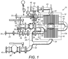
- An embodiment of the present invention will now be described, by way of example, with reference to the accompanying drawing, which schematically shows a flash steam and condensate energy recovery unit according to the present invention.
- The condensate energy recovery unit 10 (hereinafter referred to as the energy recovery unit) comprises a
cylindrical flash vessel 12, having first and secondcircular end faces second heat exchangers flash vessel 12. In other embodiments theflash vessel 12 may have a square cross-section and/or may be vertically orientated. The first andsecond heat exchangers first heat exchanger 14 is located above thesecond heat exchanger 16. The first andsecond heat exchangers - It is not essential that the first and
second heat exchangers heat exchangers second heat exchangers - The energy recovery unit is provided with a fluid feed line in the form of a
boiler feed line 18 that defines a fluid path through theflash vessel 12. Theboiler feed line 18 enters theflash vessel 12 through thefirst end wall 12a and passes through thesecond heat exchanger 16 before exiting theflash vessel 12 through thesecond end wall 12b. Thefeed line 18 is welded to the first andsecond end walls boiler feed line 18 then re-enters theflash vessel 12 through thesecond end wall 12b and passes through thefirst heat exchanger 14 before exiting theflash vessel 12 through thefirst end wall 12a. Again, thefeed line 18 is welded to the first andsecond end walls second heat exchangers boiler feed line 18 and therefore the fluid path passes through the first andsecond heat exchangers inlet 20 andoutlet 22 of theboiler feed line 18 are provided with a coupling flange. - The portion of the
boiler feed line 18 between theinlet 20 and theflash vessel 12 may be fitted with anenergy meter 24, atemperature gauge 26, anisolation valve 28 and astrainer 29. Thefeed line 18 may be provided with other suitable ancillaries. The portion of theboiler feed line 18 between theflash vessel 12 and theoutlet 22 is provided with anisolation valve 30 and atemperature gauge 32. - The
flash vessel 12 is provided with first andsecond condensate outlets first condensate outlet 34 is positioned at the bottom of theflash vessel 12 and thesecond condensate outlet 36 is located above thefirst condensate outlet 34 in theend wall 12a of theflash vessel 12. The first andsecond condensate outlets pipework 38 to asteam trap 39. Theoutlet 40 of the steam trap is provided with a coupling flange. As will be readily apparent to one skilled in the art, only one condensate outlet is necessary. - The
flash vessel 12 is also provided with aflash steam outlet 42 that is located at the top of theflash vessel 12. Aflash outlet pipe 43 connects theflash steam outlet 42 to apressure control valve 44, theoutlet 46 of which is provided with a coupling flange. - The
energy recovery unit 10 also comprises acondensate inlet pipe 48, a portion of which extends into theflash vessel 12 through thefirst end wall 12a. The portion of thecondensate inlet pipe 48 located within theflash vessel 12 has a right-angle bend 49 that is angled downwards. In other embodiments theinlet pipe 48 may be straight. Theinlet pipe 48 provides theflash vessel 12 with a condensate inlet 50 (the outlet of the condensate inlet pipe 48) that is located towards the top of the stack of fins of thesecond heat exchanger 16. Thecondensate inlet 50 is located above thesecond condensate outlet 36. The portion of thecondensate inlet pipe 48 located outside of theflash vessel 12 is provided with anisolation valve 52, theinlet 54 of which is provided with a coupling flange. - The
energy recovery unit 10 further comprises abypass line 56 that provides fluid communication between theinlet 20 andoutlet 22 of theboiler feed line 18, bypassing theflash vessel 12. The inlet of thebypass line 56 is upstream of theisolation valve 28 and the outlet is downstream of theisolation valve 30. Thebypass line 56 is also provided with itsown isolation valve 58. Thebypass line 56 allows the feed water to bypass theheat exchangers energy recovery unit 10. - The
unit 10 is in the form of a module or "skid" which is self-contained and can be assembled off site for connection to an existing system. The components and associated pipework are mounted on a rigid support so as to be transportable from an assembly facility to the site at which the unit will be utilised. It will be appreciated that the pipework couplings of the unit are all situated and oriented in the unit so as to make connection to the associated existing pipework relatively simple. Thus they are situated at or close to the outer extremity of the unit and face outwardly, unobstructed by other pipes or ancillaries. Further, provided that the relative locations of existing pipework connectors are known, the unit can be assembled off site and can be installed rapidly once delivered to site by making the appropriate pipework connections. - In use, the coupling flanges of the
energy recovery unit 10 are connected to the existing pipework of a steam utilisation system. - The
energy recovery unit 10 is connected with theinlet 20 of theboiler feed line 18 connected to a feed tank (not shown) and theoutlet 22 of theboiler feed line 18 connected to pipework leading to a boiler (not shown). Theoutlet 40 of thesteam trap 39 is connected to pipework leading to the feed tank (not shown) and theoutlet 46 of thepressure control valve 44 is connected to an excess flash steam line (not shown). Theinlet 54 of thecondensate inlet pipe 48 is connected to the steam utilisation system such that condensate can enter theflash vessel 12 through thecondensate inlet 50 of theflash vessel 12. - In normal operation the
isolation valves boiler feed line 18 are open and theisolation valve 58 of thebypass line 56 is closed. This allows boiler feed water to flow from the feed tank, through theboiler feed line 18 of the energy recovery unit to the boiler. - The
isolation valve 52 of thecondensate inlet pipe 48 is open and therefore condensate enters theflash vessel 12 through theinlet 50. As the condensate enters theflash vessel 12, the pressure is reduced and consequently at least some of the condensate flashes into steam as it enters the flash vessel. - The flash steam rises within the
flash vessel 12 and passes through the horizontal stack of fins of thefirst heat exchanger 14. Thefirst heat exchanger 14 extracts thermal energy from the flash steam and transfers it to the boiler feed water flowing in theboiler feed line 18. As heat is transferred from the flash steam to the boiler feed water the flash steam condenses and accumulates in the bottom of theflash vessel 12. Thefirst heat exchanger 14 thus operates as a vapour condenser. The condensate passes through the horizontal stack of fins of thesecond heat exchanger 16 which extracts energy from the condensate and transfers it to the boiler feed water flowing in theboiler feed line 18. Thesecond heat exchanger 16 thus operates as a condensate cooler. The cooler condensate exits theflash vessel 12 through the first and/orsecond condensate outlets steam trap 39. Any excess flash steam flows to the feed tank (not shown) through the manualpressure control valve 44 which will be set at an appropriate pressure. - The location and size of the various inlets and outlets may be chosen so as to maintain a predetermined level of condensate within the
flash vessel 12. - The
first heat exchanger 14 is designed to transfer the maximum amount of energy from the flash steam to the boiler feed water. Similarly, thesecond heat exchanger 16 is designed to transfer the maximum amount of energy from the condensate to the boiler feed water. The first andsecond heat exchangers second heat exchangers - As an example, the boiler feed water may enter the
boiler feed line 18 through theinlet 20 at a temperature of 85°C. The water may be heated to approximately 115°C by thesecond heat exchanger 16, and from 115°C to approximately 132°C by thefirst heat exchanger 14. Theenergy meter 24 is capable of measuring the energy gained by the boiler feed water as it flows through the energy recovery unit. The energy meter comprises three main components, namely; a flow meter, a pair of temperature sensors and a display for displaying the energy gained. The temperature gauges 26, 32 measure the temperature of the boiler feed water as it enters and exits theenergy recovery unit 10. - If necessary, the
energy recovery unit 10 can be isolated, without affecting the running of the steam utilising system which it serves, by closing theisolation valves boiler feed line 18 and opening theisolation valve 58 of thebypass line 56. In this configuration the boiler feed water bypasses the first andsecond heat exchangers flash vessel 12 can be inspected using aninspection hole 13. - The energy recovery unit recovers energy from both flash steam and condensate and uses this steam to pre-heat boiler feed water. As the boiler feed water is preheated, the energy demand of the boiler is reduced.
- The flash steam and condensate
energy recovery unit 10 is designed so as to utilise off-the-shelf components, so that the unit can be constructed at relatively low cost, and so that any component requiring replacement can be replaced rapidly and economically. In practice, it is expected that the cost of the condensate recovery unit will be covered, by the resulting energy savings, in less than two years of standard operation. - Locating first and
second heat exchangers single vessel 12 reduces the overall size of the energy recovery unit when compared with prior art systems such as that disclosed inUS 4878457 . - By recovering substantially all waste heat held in the collected condensate, and returning it to the feed tank, the requirement for make-up water is significantly reduced. this also reduces the requirement for chemical additives that need to be added to any make-up water to maintain the required levels of chemicals in the boiler.
Claims (13)
- An energy recovery unit (10), comprising:a flash vessel (12) having a condensate inlet (50) and a condensate outlet (34, 36);a fluid feed line (18) defining a fluid path; andfirst and second heat exchangers (14, 16) located within the flash vessel (12);characterized in that:the fluid feed line (18) passes through the flash vessel (12) so that the fluid path passes through the first and the second heat exchangers (14, 16);the first heat exchanger (14) is arranged to transfer heat from flash vapour formed from the condensate inlet to the flash vessel (12) to fluid in the fluid feed line (18), thereby condensing the flash vapour to form condensate; andthe second heat exchanger (16) is arranged to transfer heat from the condensate formed from flash vapour to fluid in the fluid feed line (18).
- An energy recovery unit (10) according to claim 1, wherein the first heat exchanger (14) is located above the second heat exchanger (16) in the flash vessel (12).
- An energy recovery unit (10) according to claim 1 or 2, wherein the first and/or second heat exchanger (14, 16) comprises a plurality of heat transfer fins in thermal contact with the fluid feed line.
- An energy recovery unit (10) according to claim 3, wherein the plurality of fins are stacked horizontally.
- An energy recovery unit (10) according to any proceeding claim, wherein the condensate inlet (50) is arranged to direct condensate towards the second heat exchanger (16).
- An energy recovery unit (10) according to any proceeding claim, wherein the condensate outlet (34) is located towards the bottom of the flash vessel (12).
- An energy recovery unit (10) according to any preceding claim, further comprising a second condensate outlet (36) located above the condensate outlet (34).
- An energy recovery unit (10) according to any preceding claim, wherein a condensate outlet pipe (38) connects the or each condensate outlet to a steam trap (39).
- An energy recovery unit (10) according to any preceding claim, further comprising a flash vapour outlet (42).
- An energy recovery unit (10) according to claim 9, wherein the flash vapour outlet (42) is located towards the top of the flash vessel (12).
- An energy recovery unit (10) according to claim 9 or 10, wherein a flash vapour outlet pipe (43) connects the flash vapour outlet (42) to a pressure control valve (44).
- An energy recovery unit (10) according to any preceding claim, wherein the fluid feed line (18) is a boiler feed line.
- A steam utilisation system including an energy recovery unit (10) in accordance with any one of the preceding claims.
Applications Claiming Priority (1)
| Application Number | Priority Date | Filing Date | Title |
|---|---|---|---|
| GB1003960A GB2478569A (en) | 2010-03-10 | 2010-03-10 | Energy recovery unit with flash steam and condensate heat exchangers |
Publications (3)
| Publication Number | Publication Date |
|---|---|
| EP2369228A2 EP2369228A2 (en) | 2011-09-28 |
| EP2369228A3 EP2369228A3 (en) | 2014-08-27 |
| EP2369228B1 true EP2369228B1 (en) | 2017-04-05 |
Family
ID=42136751
Family Applications (1)
| Application Number | Title | Priority Date | Filing Date |
|---|---|---|---|
| EP11154086.0A Active EP2369228B1 (en) | 2010-03-10 | 2011-02-10 | Energy recovery unit |
Country Status (5)
| Country | Link |
|---|---|
| US (1) | US20110220326A1 (en) |
| EP (1) | EP2369228B1 (en) |
| JP (1) | JP2011185594A (en) |
| CN (1) | CN102679317A (en) |
| GB (1) | GB2478569A (en) |
Families Citing this family (1)
| Publication number | Priority date | Publication date | Assignee | Title |
|---|---|---|---|---|
| CN107741010A (en) * | 2017-11-16 | 2018-02-27 | 陕西西咸新区博源能源工程有限公司 | A kind of boiler blowdown water waste heat and water resource recycling system |
Family Cites Families (26)
| Publication number | Priority date | Publication date | Assignee | Title |
|---|---|---|---|---|
| US1790306A (en) * | 1931-01-27 | hudson | ||
| US2060078A (en) * | 1936-02-07 | 1936-11-10 | James C Hobbs | Heat exchanger |
| US2812164A (en) * | 1953-09-17 | 1957-11-05 | Lummus Co | Heat exchanger |
| DE1078138B (en) * | 1956-06-21 | 1960-03-24 | Atlas Werke Ag | Steam-heated, horizontal surface heat exchanger for feed water or other coolants |
| US2995341A (en) * | 1959-01-08 | 1961-08-08 | Griscom Russell Co | Feed water heater sub-cooling zone |
| GB913533A (en) * | 1960-04-14 | 1962-12-19 | English Electric Co Ltd | Improvements in and relating to feed water heaters |
| US3390722A (en) * | 1965-12-16 | 1968-07-02 | Worthington Corp | Vertical feedwater heater drain coolers |
| US3795273A (en) * | 1972-06-12 | 1974-03-05 | Foster Wheeler Corp | Feedwater heater |
| US3938588A (en) * | 1973-10-18 | 1976-02-17 | Westinghouse Electric Corporation | Deaerating feedwater heater |
| DE2820736A1 (en) * | 1978-05-12 | 1979-11-15 | Bbc Brown Boveri & Cie | FEED WATER PREHEATER |
| CA1156886A (en) * | 1979-11-21 | 1983-11-15 | Ardell Beckett | Waste heat recovery system |
| SE429260B (en) * | 1981-12-29 | 1983-08-22 | Stal Laval Turbin Ab | Preheater for feedwater |
| US4393816A (en) * | 1982-02-10 | 1983-07-19 | Bock Paul A | Thermodynamic method for steam-water separation |
| US4462339A (en) * | 1983-08-29 | 1984-07-31 | Texaco Development Corporation | Gas cooler for production of saturated or superheated steam, or both |
| JPS60128170U (en) * | 1984-02-08 | 1985-08-28 | 株式会社日立製作所 | Heat exchanger |
| EP0192918B1 (en) * | 1985-02-25 | 1989-05-31 | Hamon-Sobelco S.A. | Preheater for a thermal-energy transformation plant |
| FR2581162B1 (en) * | 1985-04-24 | 1988-09-09 | Electricite De France | STEAM GENERATOR FOOD WATER HEATER |
| JPS61186911U (en) * | 1985-05-09 | 1986-11-21 | ||
| JPH0665923B2 (en) * | 1985-05-22 | 1994-08-24 | 株式会社日立製作所 | Prevention method of pipe end erosion of feed water heater |
| US4878457A (en) * | 1988-10-17 | 1989-11-07 | Martin Bekedam | Zero flash closed condensate boiler feedwater system |
| CN1022199C (en) * | 1989-06-21 | 1993-09-22 | 奥马特涡轮(1965)有限公司 | Heat exchanger for condensing vapor containing non-condensable gases |
| US5626102A (en) * | 1996-03-14 | 1997-05-06 | Nir; Ari | Heat recovery system for a boiler and a boiler provided therewith |
| CN2301607Y (en) * | 1997-10-24 | 1998-12-23 | 方立斌 | Boiler condensed water recovery heat exchange device |
| JP2004245547A (en) * | 2003-02-17 | 2004-09-02 | Samson Co Ltd | Steam generator with feed water preheater |
| CN100458314C (en) * | 2007-07-06 | 2009-02-04 | 姜玉贵 | Low temperature heat energy recovery and utilization technology |
| CN201387244Y (en) * | 2009-03-31 | 2010-01-20 | 四平市吉泰热力设备有限公司 | Steam-water heat exchanger |
-
2010
- 2010-03-10 GB GB1003960A patent/GB2478569A/en not_active Withdrawn
-
2011
- 2011-02-10 EP EP11154086.0A patent/EP2369228B1/en active Active
- 2011-03-10 US US13/045,204 patent/US20110220326A1/en not_active Abandoned
- 2011-03-10 JP JP2011053052A patent/JP2011185594A/en active Pending
- 2011-03-10 CN CN2011100582333A patent/CN102679317A/en active Pending
Non-Patent Citations (1)
| Title |
|---|
| None * |
Also Published As
| Publication number | Publication date |
|---|---|
| JP2011185594A (en) | 2011-09-22 |
| EP2369228A2 (en) | 2011-09-28 |
| EP2369228A3 (en) | 2014-08-27 |
| US20110220326A1 (en) | 2011-09-15 |
| GB201003960D0 (en) | 2010-04-21 |
| GB2478569A (en) | 2011-09-14 |
| CN102679317A (en) | 2012-09-19 |
Similar Documents
| Publication | Publication Date | Title |
|---|---|---|
| US3979914A (en) | Process and apparatus for superheating partly expanded steam | |
| CN102183007A (en) | Waste heat recovering system of boiler | |
| CN102483227A (en) | Heater for creating steam for a solar thermal power plant | |
| JP2013539006A (en) | Waste heat boiler | |
| CN102844101B (en) | There is the chemical reactor of heat-exchangers of the plate type | |
| CA2539331C (en) | Apparatus and process for detecting condensation in a heat exchanger | |
| US11454452B2 (en) | Heat exchanger for a molten salt steam generator in a concentrated solar power plant (III) | |
| EP2369228B1 (en) | Energy recovery unit | |
| CN102200403A (en) | Branch-control and phase-change heat exchange system and method based on two-stage steam-liquid heat exchanger | |
| US11359516B2 (en) | System and method for eliminating the presence of droplets in a heat exchanger | |
| US11725856B2 (en) | Refrigerant processing unit, a method for evaporating a refrigerant and use of a refrigerant processing unit | |
| US8230686B2 (en) | Start-up system mixing sphere | |
| CN109868514A (en) | A kind of vapor-recovery system and control method of acrylic spinning production definition device | |
| SA516370564B1 (en) | A Shell-and-Tube Apparatus for Heat Recovery from a Hot Process Stream | |
| TW201529961A (en) | Heat exchanging system and method for a heat recovery steam generator | |
| CN219120758U (en) | Secondary flash evaporation gas waste heat utilization device | |
| CN219265104U (en) | ORC is with integration heat exchanger | |
| JPH0665955B2 (en) | Heat exchanger | |
| CN210485686U (en) | Boiler feed water heating device and boiler | |
| RU2378571C1 (en) | Heat exchanger vertical | |
| CN219756337U (en) | Automatic blowdown heat recovery unit of boiler | |
| EP3321419B1 (en) | Multi stage washing column and device for drying wetted material comprising a multi stage washing column | |
| WO2016096847A1 (en) | System and method for fluid medium preheating | |
| CN104613458B (en) | The heat energy comprehensive utilization device of the therrmodynamic system containing steam boiler | |
| HEATER et al. | SPECIAL HEAT EXCHANGE APPARATUS: Catalog on request. |
Legal Events
| Date | Code | Title | Description |
|---|---|---|---|
| PUAI | Public reference made under article 153(3) epc to a published international application that has entered the european phase |
Free format text: ORIGINAL CODE: 0009012 |
|
| AK | Designated contracting states |
Kind code of ref document: A2 Designated state(s): AL AT BE BG CH CY CZ DE DK EE ES FI FR GB GR HR HU IE IS IT LI LT LU LV MC MK MT NL NO PL PT RO RS SE SI SK SM TR |
|
| AX | Request for extension of the european patent |
Extension state: BA ME |
|
| PUAL | Search report despatched |
Free format text: ORIGINAL CODE: 0009013 |
|
| AK | Designated contracting states |
Kind code of ref document: A3 Designated state(s): AL AT BE BG CH CY CZ DE DK EE ES FI FR GB GR HR HU IE IS IT LI LT LU LV MC MK MT NL NO PL PT RO RS SE SI SK SM TR |
|
| AX | Request for extension of the european patent |
Extension state: BA ME |
|
| RIC1 | Information provided on ipc code assigned before grant |
Ipc: F22D 1/32 20060101AFI20140722BHEP Ipc: F22B 3/04 20060101ALI20140722BHEP |
|
| 17P | Request for examination filed |
Effective date: 20141008 |
|
| RBV | Designated contracting states (corrected) |
Designated state(s): AL AT BE BG CH CY CZ DE DK EE ES FI FR GB GR HR HU IE IS IT LI LT LU LV MC MK MT NL NO PL PT RO RS SE SI SK SM TR |
|
| GRAP | Despatch of communication of intention to grant a patent |
Free format text: ORIGINAL CODE: EPIDOSNIGR1 |
|
| RIC1 | Information provided on ipc code assigned before grant |
Ipc: F22D 1/32 20060101AFI20161115BHEP Ipc: F22B 3/04 20060101ALI20161115BHEP |
|
| INTG | Intention to grant announced |
Effective date: 20161221 |
|
| GRAS | Grant fee paid |
Free format text: ORIGINAL CODE: EPIDOSNIGR3 |
|
| GRAA | (expected) grant |
Free format text: ORIGINAL CODE: 0009210 |
|
| AK | Designated contracting states |
Kind code of ref document: B1 Designated state(s): AL AT BE BG CH CY CZ DE DK EE ES FI FR GB GR HR HU IE IS IT LI LT LU LV MC MK MT NL NO PL PT RO RS SE SI SK SM TR |
|
| REG | Reference to a national code |
Ref country code: GB Ref legal event code: FG4D |
|
| REG | Reference to a national code |
Ref country code: CH Ref legal event code: EP |
|
| REG | Reference to a national code |
Ref country code: AT Ref legal event code: REF Ref document number: 882175 Country of ref document: AT Kind code of ref document: T Effective date: 20170415 |
|
| REG | Reference to a national code |
Ref country code: IE Ref legal event code: FG4D |
|
| REG | Reference to a national code |
Ref country code: DE Ref legal event code: R096 Ref document number: 602011036580 Country of ref document: DE |
|
| REG | Reference to a national code |
Ref country code: NL Ref legal event code: MP Effective date: 20170405 |
|
| REG | Reference to a national code |
Ref country code: LT Ref legal event code: MG4D |
|
| REG | Reference to a national code |
Ref country code: AT Ref legal event code: MK05 Ref document number: 882175 Country of ref document: AT Kind code of ref document: T Effective date: 20170405 |
|
| PG25 | Lapsed in a contracting state [announced via postgrant information from national office to epo] |
Ref country code: NL Free format text: LAPSE BECAUSE OF FAILURE TO SUBMIT A TRANSLATION OF THE DESCRIPTION OR TO PAY THE FEE WITHIN THE PRESCRIBED TIME-LIMIT Effective date: 20170405 |
|
| PG25 | Lapsed in a contracting state [announced via postgrant information from national office to epo] |
Ref country code: NO Free format text: LAPSE BECAUSE OF FAILURE TO SUBMIT A TRANSLATION OF THE DESCRIPTION OR TO PAY THE FEE WITHIN THE PRESCRIBED TIME-LIMIT Effective date: 20170705 Ref country code: AT Free format text: LAPSE BECAUSE OF FAILURE TO SUBMIT A TRANSLATION OF THE DESCRIPTION OR TO PAY THE FEE WITHIN THE PRESCRIBED TIME-LIMIT Effective date: 20170405 Ref country code: ES Free format text: LAPSE BECAUSE OF FAILURE TO SUBMIT A TRANSLATION OF THE DESCRIPTION OR TO PAY THE FEE WITHIN THE PRESCRIBED TIME-LIMIT Effective date: 20170405 Ref country code: HR Free format text: LAPSE BECAUSE OF FAILURE TO SUBMIT A TRANSLATION OF THE DESCRIPTION OR TO PAY THE FEE WITHIN THE PRESCRIBED TIME-LIMIT Effective date: 20170405 Ref country code: LT Free format text: LAPSE BECAUSE OF FAILURE TO SUBMIT A TRANSLATION OF THE DESCRIPTION OR TO PAY THE FEE WITHIN THE PRESCRIBED TIME-LIMIT Effective date: 20170405 Ref country code: GR Free format text: LAPSE BECAUSE OF FAILURE TO SUBMIT A TRANSLATION OF THE DESCRIPTION OR TO PAY THE FEE WITHIN THE PRESCRIBED TIME-LIMIT Effective date: 20170706 Ref country code: FI Free format text: LAPSE BECAUSE OF FAILURE TO SUBMIT A TRANSLATION OF THE DESCRIPTION OR TO PAY THE FEE WITHIN THE PRESCRIBED TIME-LIMIT Effective date: 20170405 |
|
| PG25 | Lapsed in a contracting state [announced via postgrant information from national office to epo] |
Ref country code: LV Free format text: LAPSE BECAUSE OF FAILURE TO SUBMIT A TRANSLATION OF THE DESCRIPTION OR TO PAY THE FEE WITHIN THE PRESCRIBED TIME-LIMIT Effective date: 20170405 Ref country code: IS Free format text: LAPSE BECAUSE OF FAILURE TO SUBMIT A TRANSLATION OF THE DESCRIPTION OR TO PAY THE FEE WITHIN THE PRESCRIBED TIME-LIMIT Effective date: 20170805 Ref country code: PL Free format text: LAPSE BECAUSE OF FAILURE TO SUBMIT A TRANSLATION OF THE DESCRIPTION OR TO PAY THE FEE WITHIN THE PRESCRIBED TIME-LIMIT Effective date: 20170405 Ref country code: BG Free format text: LAPSE BECAUSE OF FAILURE TO SUBMIT A TRANSLATION OF THE DESCRIPTION OR TO PAY THE FEE WITHIN THE PRESCRIBED TIME-LIMIT Effective date: 20170705 Ref country code: SE Free format text: LAPSE BECAUSE OF FAILURE TO SUBMIT A TRANSLATION OF THE DESCRIPTION OR TO PAY THE FEE WITHIN THE PRESCRIBED TIME-LIMIT Effective date: 20170405 Ref country code: RS Free format text: LAPSE BECAUSE OF FAILURE TO SUBMIT A TRANSLATION OF THE DESCRIPTION OR TO PAY THE FEE WITHIN THE PRESCRIBED TIME-LIMIT Effective date: 20170405 |
|
| REG | Reference to a national code |
Ref country code: DE Ref legal event code: R097 Ref document number: 602011036580 Country of ref document: DE |
|
| PG25 | Lapsed in a contracting state [announced via postgrant information from national office to epo] |
Ref country code: SK Free format text: LAPSE BECAUSE OF FAILURE TO SUBMIT A TRANSLATION OF THE DESCRIPTION OR TO PAY THE FEE WITHIN THE PRESCRIBED TIME-LIMIT Effective date: 20170405 Ref country code: RO Free format text: LAPSE BECAUSE OF FAILURE TO SUBMIT A TRANSLATION OF THE DESCRIPTION OR TO PAY THE FEE WITHIN THE PRESCRIBED TIME-LIMIT Effective date: 20170405 Ref country code: EE Free format text: LAPSE BECAUSE OF FAILURE TO SUBMIT A TRANSLATION OF THE DESCRIPTION OR TO PAY THE FEE WITHIN THE PRESCRIBED TIME-LIMIT Effective date: 20170405 Ref country code: CZ Free format text: LAPSE BECAUSE OF FAILURE TO SUBMIT A TRANSLATION OF THE DESCRIPTION OR TO PAY THE FEE WITHIN THE PRESCRIBED TIME-LIMIT Effective date: 20170405 Ref country code: DK Free format text: LAPSE BECAUSE OF FAILURE TO SUBMIT A TRANSLATION OF THE DESCRIPTION OR TO PAY THE FEE WITHIN THE PRESCRIBED TIME-LIMIT Effective date: 20170405 |
|
| PLBE | No opposition filed within time limit |
Free format text: ORIGINAL CODE: 0009261 |
|
| STAA | Information on the status of an ep patent application or granted ep patent |
Free format text: STATUS: NO OPPOSITION FILED WITHIN TIME LIMIT |
|
| PG25 | Lapsed in a contracting state [announced via postgrant information from national office to epo] |
Ref country code: SM Free format text: LAPSE BECAUSE OF FAILURE TO SUBMIT A TRANSLATION OF THE DESCRIPTION OR TO PAY THE FEE WITHIN THE PRESCRIBED TIME-LIMIT Effective date: 20170405 Ref country code: IT Free format text: LAPSE BECAUSE OF FAILURE TO SUBMIT A TRANSLATION OF THE DESCRIPTION OR TO PAY THE FEE WITHIN THE PRESCRIBED TIME-LIMIT Effective date: 20170405 |
|
| 26N | No opposition filed |
Effective date: 20180108 |
|
| PG25 | Lapsed in a contracting state [announced via postgrant information from national office to epo] |
Ref country code: SI Free format text: LAPSE BECAUSE OF FAILURE TO SUBMIT A TRANSLATION OF THE DESCRIPTION OR TO PAY THE FEE WITHIN THE PRESCRIBED TIME-LIMIT Effective date: 20170405 |
|
| REG | Reference to a national code |
Ref country code: DE Ref legal event code: R119 Ref document number: 602011036580 Country of ref document: DE |
|
| REG | Reference to a national code |
Ref country code: CH Ref legal event code: PL |
|
| PG25 | Lapsed in a contracting state [announced via postgrant information from national office to epo] |
Ref country code: MC Free format text: LAPSE BECAUSE OF FAILURE TO SUBMIT A TRANSLATION OF THE DESCRIPTION OR TO PAY THE FEE WITHIN THE PRESCRIBED TIME-LIMIT Effective date: 20170405 |
|
| REG | Reference to a national code |
Ref country code: IE Ref legal event code: MM4A |
|
| REG | Reference to a national code |
Ref country code: BE Ref legal event code: MM Effective date: 20180228 |
|
| PG25 | Lapsed in a contracting state [announced via postgrant information from national office to epo] |
Ref country code: LU Free format text: LAPSE BECAUSE OF NON-PAYMENT OF DUE FEES Effective date: 20180210 Ref country code: LI Free format text: LAPSE BECAUSE OF NON-PAYMENT OF DUE FEES Effective date: 20180228 Ref country code: CH Free format text: LAPSE BECAUSE OF NON-PAYMENT OF DUE FEES Effective date: 20180228 |
|
| REG | Reference to a national code |
Ref country code: FR Ref legal event code: ST Effective date: 20181031 |
|
| PG25 | Lapsed in a contracting state [announced via postgrant information from national office to epo] |
Ref country code: DE Free format text: LAPSE BECAUSE OF NON-PAYMENT OF DUE FEES Effective date: 20180901 Ref country code: IE Free format text: LAPSE BECAUSE OF NON-PAYMENT OF DUE FEES Effective date: 20180210 |
|
| PG25 | Lapsed in a contracting state [announced via postgrant information from national office to epo] |
Ref country code: BE Free format text: LAPSE BECAUSE OF NON-PAYMENT OF DUE FEES Effective date: 20180228 Ref country code: FR Free format text: LAPSE BECAUSE OF NON-PAYMENT OF DUE FEES Effective date: 20180228 |
|
| PG25 | Lapsed in a contracting state [announced via postgrant information from national office to epo] |
Ref country code: MT Free format text: LAPSE BECAUSE OF NON-PAYMENT OF DUE FEES Effective date: 20180210 |
|
| PG25 | Lapsed in a contracting state [announced via postgrant information from national office to epo] |
Ref country code: TR Free format text: LAPSE BECAUSE OF FAILURE TO SUBMIT A TRANSLATION OF THE DESCRIPTION OR TO PAY THE FEE WITHIN THE PRESCRIBED TIME-LIMIT Effective date: 20170405 |
|
| PG25 | Lapsed in a contracting state [announced via postgrant information from national office to epo] |
Ref country code: HU Free format text: LAPSE BECAUSE OF FAILURE TO SUBMIT A TRANSLATION OF THE DESCRIPTION OR TO PAY THE FEE WITHIN THE PRESCRIBED TIME-LIMIT; INVALID AB INITIO Effective date: 20110210 Ref country code: PT Free format text: LAPSE BECAUSE OF FAILURE TO SUBMIT A TRANSLATION OF THE DESCRIPTION OR TO PAY THE FEE WITHIN THE PRESCRIBED TIME-LIMIT Effective date: 20170405 |
|
| PG25 | Lapsed in a contracting state [announced via postgrant information from national office to epo] |
Ref country code: CY Free format text: LAPSE BECAUSE OF FAILURE TO SUBMIT A TRANSLATION OF THE DESCRIPTION OR TO PAY THE FEE WITHIN THE PRESCRIBED TIME-LIMIT Effective date: 20170405 Ref country code: MK Free format text: LAPSE BECAUSE OF NON-PAYMENT OF DUE FEES Effective date: 20170405 |
|
| PG25 | Lapsed in a contracting state [announced via postgrant information from national office to epo] |
Ref country code: AL Free format text: LAPSE BECAUSE OF FAILURE TO SUBMIT A TRANSLATION OF THE DESCRIPTION OR TO PAY THE FEE WITHIN THE PRESCRIBED TIME-LIMIT Effective date: 20170405 |
|
| PGFP | Annual fee paid to national office [announced via postgrant information from national office to epo] |
Ref country code: GB Payment date: 20230220 Year of fee payment: 13 |
|
| P01 | Opt-out of the competence of the unified patent court (upc) registered |
Effective date: 20230524 |