EP2369192B1 - Doppelsteuereinheit mit linearer Bewegung und entsprechendes Produktionsverfahren - Google Patents
Doppelsteuereinheit mit linearer Bewegung und entsprechendes Produktionsverfahren Download PDFInfo
- Publication number
- EP2369192B1 EP2369192B1 EP11001932.0A EP11001932A EP2369192B1 EP 2369192 B1 EP2369192 B1 EP 2369192B1 EP 11001932 A EP11001932 A EP 11001932A EP 2369192 B1 EP2369192 B1 EP 2369192B1
- Authority
- EP
- European Patent Office
- Prior art keywords
- guide
- groove
- parallel
- holes
- linear
- Prior art date
- Legal status (The legal status is an assumption and is not a legal conclusion. Google has not performed a legal analysis and makes no representation as to the accuracy of the status listed.)
- Not-in-force
Links
- 238000004519 manufacturing process Methods 0.000 title claims description 9
- 230000000712 assembly Effects 0.000 claims description 12
- 238000000429 assembly Methods 0.000 claims description 12
- 230000008878 coupling Effects 0.000 claims description 7
- 238000010168 coupling process Methods 0.000 claims description 7
- 238000005859 coupling reaction Methods 0.000 claims description 7
- 238000000605 extraction Methods 0.000 claims description 4
- 239000002184 metal Substances 0.000 claims description 4
- 238000000034 method Methods 0.000 claims description 4
- 230000013011 mating Effects 0.000 claims description 2
- 238000006073 displacement reaction Methods 0.000 description 6
- 238000012423 maintenance Methods 0.000 description 2
- 230000000295 complement effect Effects 0.000 description 1
- 230000006835 compression Effects 0.000 description 1
- 238000007906 compression Methods 0.000 description 1
- 230000001419 dependent effect Effects 0.000 description 1
- 238000001125 extrusion Methods 0.000 description 1
- 238000003754 machining Methods 0.000 description 1
Images



Classifications
-
- F—MECHANICAL ENGINEERING; LIGHTING; HEATING; WEAPONS; BLASTING
- F16—ENGINEERING ELEMENTS AND UNITS; GENERAL MEASURES FOR PRODUCING AND MAINTAINING EFFECTIVE FUNCTIONING OF MACHINES OR INSTALLATIONS; THERMAL INSULATION IN GENERAL
- F16C—SHAFTS; FLEXIBLE SHAFTS; ELEMENTS OR CRANKSHAFT MECHANISMS; ROTARY BODIES OTHER THAN GEARING ELEMENTS; BEARINGS
- F16C29/00—Bearings for parts moving only linearly
- F16C29/008—Systems with a plurality of bearings, e.g. four carriages supporting a slide on two parallel rails
-
- B—PERFORMING OPERATIONS; TRANSPORTING
- B23—MACHINE TOOLS; METAL-WORKING NOT OTHERWISE PROVIDED FOR
- B23Q—DETAILS, COMPONENTS, OR ACCESSORIES FOR MACHINE TOOLS, e.g. ARRANGEMENTS FOR COPYING OR CONTROLLING; MACHINE TOOLS IN GENERAL CHARACTERISED BY THE CONSTRUCTION OF PARTICULAR DETAILS OR COMPONENTS; COMBINATIONS OR ASSOCIATIONS OF METAL-WORKING MACHINES, NOT DIRECTED TO A PARTICULAR RESULT
- B23Q1/00—Members which are comprised in the general build-up of a form of machine, particularly relatively large fixed members
- B23Q1/25—Movable or adjustable work or tool supports
- B23Q1/44—Movable or adjustable work or tool supports using particular mechanisms
- B23Q1/56—Movable or adjustable work or tool supports using particular mechanisms with sliding pairs only, the sliding pairs being the first two elements of the mechanism
- B23Q1/58—Movable or adjustable work or tool supports using particular mechanisms with sliding pairs only, the sliding pairs being the first two elements of the mechanism a single sliding pair
-
- F—MECHANICAL ENGINEERING; LIGHTING; HEATING; WEAPONS; BLASTING
- F16—ENGINEERING ELEMENTS AND UNITS; GENERAL MEASURES FOR PRODUCING AND MAINTAINING EFFECTIVE FUNCTIONING OF MACHINES OR INSTALLATIONS; THERMAL INSULATION IN GENERAL
- F16C—SHAFTS; FLEXIBLE SHAFTS; ELEMENTS OR CRANKSHAFT MECHANISMS; ROTARY BODIES OTHER THAN GEARING ELEMENTS; BEARINGS
- F16C29/00—Bearings for parts moving only linearly
- F16C29/04—Ball or roller bearings
- F16C29/06—Ball or roller bearings in which the rolling bodies circulate partly without carrying load
- F16C29/0633—Ball or roller bearings in which the rolling bodies circulate partly without carrying load with a bearing body defining a U-shaped carriage, i.e. surrounding a guide rail or track on three sides
-
- F—MECHANICAL ENGINEERING; LIGHTING; HEATING; WEAPONS; BLASTING
- F16—ENGINEERING ELEMENTS AND UNITS; GENERAL MEASURES FOR PRODUCING AND MAINTAINING EFFECTIVE FUNCTIONING OF MACHINES OR INSTALLATIONS; THERMAL INSULATION IN GENERAL
- F16C—SHAFTS; FLEXIBLE SHAFTS; ELEMENTS OR CRANKSHAFT MECHANISMS; ROTARY BODIES OTHER THAN GEARING ELEMENTS; BEARINGS
- F16C2322/00—Apparatus used in shaping articles
- F16C2322/39—General buildup of machine tools, e.g. spindles, slides, actuators
Definitions
- the present invention relates to a linear motion double guide unit device, with linear motion integrated drive.
- the invention also relates to the production process of this device.
- a linear motion single guide unit device comprises a hollow structural element extending according to a longitudinal axis, hereinafter called beam, and having a bottom wall and two lateral walls, which delimit a guide cavity.
- the aforesaid linear motion single guide unit also comprises a rectilinear guide, called single rail guide, parallel to said axis and secured on the bottom wall inside the guide cavity.
- a slide assembly is superimposed and mounted sliding along said single rail guide and includes an upper carriage part and at least one lower saddle, integral with said carriage and engaged for sliding with respect to the single rail guide.
- linear movement control and drive means for displacement of the slide assembly in the direction of the longitudinal axis along the rectilinear guide.
- said control and drive means comprise a flexible traction member, for example a toothed belt, which starting from one longitudinal end of the carriage, to which it is secured, partially surrounds two guide pulleys respectively provided in proximity of each of the two ends of the guide beam, with essentially transverse axis. Said flexible member is also secured to said carriage, with the other end thereof, in a closed loop configuration.
- Rotation control means for example an electric gear motor, are kinematically connected to one of said pulleys, while the other pulley is mounted idle.
- said control and drive means comprise a screw/nut screw mechanism, wherein the screw extends in the longitudinal direction of the guide beam, is mounted axially fixed and rotating with respect to said beam and is kinematically connected with respect to rotation drive means, for example electric gear motor means. Said screw is engaged by helical coupling with respect to a nut screw, for example of the type with internally threaded nut, secured with respect to the slide assembly.
- control and drive means for displacement of said slide assembly with respect to said single rail rectilinear guide means.
- control and drive means include rack means, extending in said guide cavity parallel to said longitudinal axis, and a drive unit including pinion means meshed with respect to said rack means and controlled in rotation by means of rotation driving means.
- Said rack means are, for example, secured with respect to a wall of said linear guide hollow beam and project with a toothed part thereof inside said guide cavity, while said pinion means are supported by said slide assembly.
- a linear motion double guide unit device comprises a beam element, produced in one piece, extending according to a longitudinal axis and having two longitudinal guide cavities, adjacent and parallel to said axis, and two respective single rail rectilinear guides, each secured parallel to said axis on the bottom wall of a corresponding guide cavity.
- a slide assembly is superimposed and mounted sliding along the two rectilinear guides and includes a single upper carriage part and at least two lower saddles, integral with said carriage and each engaged by sliding along a respective rail rectilinear guide.
- This known linear motion double guide unit device comprises its own control and drive means, of the type with toothed belt on pulleys or of the screw and nut screw type as described above, for displacement of the corresponding slide assembly with respect to the two single rail rectilinear guides.
- the aforesaid known linear motion double guide unit device is advantageously used when the load is applied in a cantilever fashion with respect to the guide unit.
- a load of this kind generates an overturning moment on the single rail guide.
- This overturning moment if applied to a single guide unit device, besides causing possible structural failure of the lower saddle of the slide assembly, considerably reduces the working life of the device.
- the two single rail rectilinear guides and the respective lower saddles of the slide assembly efficiently counteract the overturning moment applied and are mainly subjected to tensile and compression stress, working in an optimal condition. Therefore, the operating precision and working life of the device are considerably increased.
- the aforesaid known linear motion double guide unit device has the drawback that the beam body with double guide cavity and the relative slide assembly are each conceived and produced as a structurally single entity and therefore are not modularly mountable: this fact leads to a relatively high technical and economic expenditure.
- the present invention intends to provide a remedy.
- An object of the invention is to provide a linear motion double guide unit device, with linear motion integrated drive, in which both the beam body with double guide cavity and the relative slide assembly are each modularly mountable, so as to make the device structurally simplified and versatile in use.
- Another object of the present invention is to provide a linear motion double guide unit device, with linear motion integrated drive, which has safe and reliable operation, which is easy to perform maintenance on and which has relatively limited costs.
- Yet another object of the invention is to provide a production process of the aforesaid device, which allows simplification of the machining steps and of any maintenance of the device, with consequent reduction in technical and economic expenditure.
- the present invention provides a linear motion double guide unit device, with linear motion integrated drive, the fundamental characteristic of which is described in claim 1.
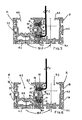
- linear motion double guide unit device with linear motion integrated drive, according to the invention is indicated as a whole with 10.
- Said device 10 includes two linear motion guide units 10.1 mutually coupled in parallel and comprises, in particular, a structural body 10.2, wherein two hollow linear guide beams 11, substantially identical, are mutually juxtaposed and secured side by side, in demountable manner, and extend parallel according to a longitudinal axis.
- Each hollow linear guide beam 11 has a substantially horizontal bottom wall 11.1 and two substantially vertical lateral walls 11.2, which delimit a guide cavity 11.3.
- each linear guide beam 11 is formed by a single piece body, with a substantially equilateral U-shaped cross section, obtained by extrusion.
- said single piece body is closed at the longitudinal ends thereof by means of respective heads 11.4.
- each linear motion guide unit forms a structurally autonomous entity and comprises a respective beam of said two hollow linear guide beams 11.
- Each linear guide beam 11 comprises, in turn, a single rail rectilinear guide 12, extending parallel to said longitudinal axis and secured, in demountable manner, with respect to the bottom wall 11.1, along the longitudinal vertical median plane of the unit.
- each slide assembly 13 is mounted sliding along the respective single rail guide 12.
- Each slide assembly 13 forms a structurally autonomous entity and includes an upper carriage part 13.1 and two lower saddles 13.20 integral with said carriage 13.1 and engaged by sliding with respect to the respective single rail rectilinear guide 12.
- Ball races 13.3 are provided in each of said saddles 13.20 in an arrangement partly surrounding said rectilinear guide 12.
- Each linear guide beam 11 has, on the outer lateral face of each of the two longitudinal lateral walls 11.2, a respective pair of assembly grooves 14, extending for the entire length parallel to said longitudinal axis, mutually staggered in height, with an opening on the respective lateral wall 11.2 and wherein the area of the cross section of each groove 14 has a trend increasing toward the inside of the beam
- each groove 14 has a cross section substantially in the shape of a "T" lying on its side.
- the two hollow linear guide beams 11 have the assembly grooves 14 in opposed pairs and with their respective openings substantially mating.
- each of said two longitudinal grooves 14 of a first of said two juxtaposed linear guide beams 11 there is housed with clearance a respective longitudinal key 15, formed by a metal profile, with cross section substantially in the shape of a "T" lying on its side and of a length essentially corresponding to that of said first linear guide beam 11.
- Said key 15 has a shape complementary to that of said groove 14 in which it is inserted and is prevented from extraction in the transverse direction of the same groove.
- said key 15 there is provided an arrangement of threaded holes 15.1, whose axes are mutually spaced in longitudinal direction according to a constant pitch and are directed parallel to the transverse direction with respect to said groove 14 in which the key 15 is inserted.
- said threaded holes 15.1 there are partially screwed the stems of corresponding assembly screws 16, which with the remaining part of their stem and their head partially occupy the opposite groove 14 in the other of said two juxtaposed linear guide beams 11.
- said slides 13 of the two units 10.1 of the device 10 according to the invention are also mutually coupled, side by side, in parallel and integrally, through a pair of transverse blocks 18, arranged bridging the slides 13 and secured with respect to the same in demountable manner.
- each slide 13 has, in the upper face of the carriage 13.1 thereof, a pair of transverse grooves 13.2 extending for the entire width thereof.
- a respective transverse block 18 In each groove 13.2 there is inserted, through positive connection, a corresponding end of a respective transverse block 18, arranged bridging the two coupled slide assemblies 13 and formed by a metal bar provided with assembly through holes 18.1 with axis essentially vertical and corresponding, for position, with respective through holes 13.4 provided in each carriage 13.1 of the same slide 13.
- Corresponding assembly screws 18.2 are inserted, through said holes 18.1 of the blocks 18 and are clamped in said holes 13.4, so as to make said same slide assemblies 13 mutually integral by means of said blocks 18 thus secured.
- said linear motion control and drive means are provided only in one of said linear motion guide units 10.1, as will be more apparent below.
- said control and drive means are provided in a first of said linear motion guide units 10.1 and comprise a flexible traction member 19, for example with toothed belt, which starting from one longitudinal end of the carriage 13.1, to which it is secured, partially surrounds two guide pulleys (not shown) respectively provided in proximity of each of the two ends of the corresponding linear guide beam 11, with essentially transverse axis.
- Said flexible member 19 is further secured to said carriage 13.1, with the other end thereof, forming a closed loop.
- Rotation control means (not shown), for example an electric gear motor, are kinematically connected to one of said pulleys, while the other pulley is mounted idle.
- said control and drive means are provided in a first of said linear motion guide units 10.1 and comprise a screw/nut screw mechanism 20, wherein the screw extends in the longitudinal direction of the corresponding linear guide beam 11, is mounted axially fixed and rotating with respect to said beam and is kinematically connected with respect to rotation drive means, for example electric gear motor means (not shown). Said screw is engaged by helical coupling with respect to a nut screw, for example of the type with internally threaded nut, secured with respect to the respective slide assembly 13 of said first guide unit 10.1.
- control and drive means for displacement of said slide assembly with respect to said single rail rectilinear guide means.
- control and drive means include rack means, extending in said guide cavity parallel to said longitudinal axis, and a drive unit including pinion means meshed with respect to said rack means and controlled in rotation by means of rotation driving means.
- Said rack means are, for example, secured with respect to a wall of said linear guide hollow beam and project with a toothed part thereof inside said guide cavity, while said pinion means are supported by said slide assembly.
- said control and drive means for linear displacement of the corresponding slide 13 are provided in only one of the two linear motion guide units 10.1, whose slide 13 in turn drives with integral motion the slide 13 of the other coupled guide unit 10.1.
- said other guide unit 10.1 without guide means, the structure of the respective slide 13 is structurally simplified and of lesser height.
- the beam 11 of said other linear unit 10.1 there is provided in an integral body a raised double bottom 11.5, on which the respective single rail guide 12 is secured in demountable manner. Operation of the double guide unit device 10 according to the present invention is apparent from the above. Therefore, further description thereof is omitted.
- the production process of the linear motion double guide unit device according to the invention comprises the following assembly steps.
- a first part of the device 10 according to the invention is produced by mutually coupling in parallel two linear motion guide units 10.1 and, in particular, forming a structural body 10.2, wherein two hollow linear guide beams 11, substantially identical, are mutually juxtaposed and secured side by side, parallel according to a longitudinal axis, in demountable manner.
- two linear motion guide units 10.1 and, in particular, forming a structural body 10.2, wherein two hollow linear guide beams 11, substantially identical, are mutually juxtaposed and secured side by side, parallel according to a longitudinal axis, in demountable manner.
- the two slide assemblies 13 of the two units 10.1 of the device 10 according to the invention are mutually coupled, side by side, in parallel and integrally.
- said two slide assemblies 13 are coupled by means of a pair of transverse blocks 18, arranged bridging the same slides and secured with respect thereto in demountable manner.
- each slide assembly 13 is a slide assembly 13:
- the linear motion double unit guide device with linear motion integrated drive, according to the present invention and as claimed, allows the objects set forth above to be achieved in an advantageous manner.
Landscapes
- Engineering & Computer Science (AREA)
- General Engineering & Computer Science (AREA)
- Mechanical Engineering (AREA)
- Bearings For Parts Moving Linearly (AREA)
- Machine Tool Units (AREA)
Claims (10)
- Lineardoppel führungseinheit, umfassend einen sich längs einer Längsachse erstreckenden Körper mit zwei parallel zu der besagten Achse verlaufenden Führungshohlräumen (11 3) und zwei entsprechenden gradlinigen Führungsschienen (12) von denen jede parallel zu dieser Achse an einer Wand (11 1) eines entsprechenden Führungshohlraums (11 3) befestigt ist, und umfassend mindestens eine längs der besagten zwei geradlinigen Führungsschienen (12) gleitend montierte Schlittengruppe (13) und aufnehmend mindestens einen karrenförmigen Teil (13 1) und mindestens zwei Wagen (13.20), die fest mit dem besagten Karren verbunden und jeweils durch Gleiten längs einer entsprechenden gradlinigen Führungsschiene engagiert sind,
dadurch gekeinzeichnet, dass
sie zwei einzelne Linearführungseinheiten (10 1) umfasst die parallel zueinander angeordnet sind, wobei jede Folgendes umfasst- ein hohles Strukturelement, das sich längs einer Längsachse erstreckt, im Folgenden linearer Führungsträger (11) genannt die einen entsprechenden Führungshohlraum (11 3) begrenzt;- eine geradlinige Führungsschiene (12) die parallel zu der besagten Achse verlauft und an de Rückwand (11 1) im Inneren des besagten Führungshohlraums (11.3) befestigt ist und- eine Schlittengruppe (13), die längs der besagten Führungsschiene (12) gleitend montiert ist und einen karrenförmigen Teil (13.1) und mindestens einen Wagen (13 20) einschließt, der fest mit dem besagten Karren verbunden und durch Gleiten in Bezug auf die besagte Führungsschiene engagiert ist;und dadurch gekennzeichnet, dass
die besagten zueinander angeordneten zwei einzelnen Linearführungseinheiten (10.1) ein Strukturelement (10 2) bilden, wobei die besagten hohlen Linearführungsträger 11) nebeneinander liegen und Seite an Seite abbaubar befestigt sind, und sich pa allel längs der besagten Längsachse erstrecken. - Vorrichtung gemäß Anspruch 1 dadurch gekennzeichnet, dass:- jede einzelne Linearführungseinheit (10 1) eine strukturell autonome Einheit bildet und eine der beiden entsprechenden hohlen Linearführungsträger (11) umfasst;- jeder Linearführungsträger (11) eine geradlinige Führungsschiene (12) umfasst, die sich parallel zu der besagten Längsachse erstreckt und in Bezug auf die besagte Rückwand (11 1) des Trägers selbst abbaubar befestigt ist;- in jeder einzelnen Linearführungseinheit (10.1) eine entsprechende Schlittengruppe (13) längs der jeweiligen Führungsschiene (12) gleitend montiert ist und eine strukturell autonome Einheit bildet, die einen karrenförmigen Teil (13 1) und mindestens einen Wagen (13 20) einschließt, der fest mit dem besagten Karren (13 1) verbunden und durch Gleiten in Bezug auf die entsprchende geradlinige Führungsschiene (12) engagiert ist.
- Vorrichtung gemäß Anspruch 1 und/oder 2 dadurch gekennzeichnet:- dass jeder Linearführungsträger (11) auf einer seitlichen Außenfläche von mindestens einer seiner beiden seitlichen Längswände (11.2), die den besagten Führungshohlraum (11 3) begrenzen, mindestens eine Montagenut (14) präsentiert, die sich auf ihrer gesamten Länge parallel zur Längsachse erstreckt und eine öffnung auf der besagten Außenfläche aufweist;- dass in den parallel zueinander angeordneten beiden einzelnen Linearführungseinheiten (10 1) die besagten zwei hohlen Linearführungsträger (11) die jeweiligen Montagenuten (14) so aufweisen, dass sie jeweils zu zweit gegenüberliegen, wobei ihre Öffnungen im Wesentlichen miteinander übereinstimmen;- durch gekennzeichnet, dass:- in mindestens einer Längsnut (14) eines ersten de besagten nebeneinanderliegenden Fuhrungstrager (11) ein entsprechender Längskeil (15) untergebracht ist, der gegen Herausziehen in Querrichtung der Nut selbst verhindert ist;- in dem besagten Keil (15) Gewindelöcher (15 1) angeordnet sind, deren Achsen in Längsrichtung jeweils in einem gewisseen Abstand liegen und in Verrichtung zu dieser Nut (14) in die der Keil (15) eingesetzt ist, parallel verlaufen;- in den besagten Gewindelöchern (15.1) die Schäfte der entsprechenden Montageschrauben (16) teilweise verschraubt sind, so dass diese im Wesentlichen mit dem verbleibenden Teil ihres Schaftes und ihres Kopfes die Nut (14) die der im anderen der beiden nebeneinanderliegenden Linearführungsträger (11) gegenüberliegt, zum Teil einnehmen;
und dadurch gekennzeichnet dass:- in der Seitenwand (11 2) die der anderen der besagten zwei nebeneinanderliegenden Linearführungsträger (11) gegenüberliegt, langs der Nut (14) die der des besagten ersten Linearfürungsträgers (11) entspricht, in der der besagte Keil (15) untergebracht ist, eine Anordnung durchgehender Montagelocher (17) in der Querachse vorgesehen ist, die auf der einen Seite mit dem Führungshohlraum (11 3) des besagten anderen Linearfuhrungst rägers (11) und auf der anderen Seite mit der Nut (14) selbst in Verbindung stehen- die Achsen der besagten Löcher (17) jeweils in Längsrichtung in einem gewissen Abstand liegen, wobei der Abstand der dem der Achsen der Locher (15 1) des besagten Keils (15) entspricht, und die Löcher (17) einer jeden Anordnung von Löchern den Köpfen der besagten Schrauben (16) die die Nut (14) in de die Löcher münden, in Anspruch nehmen, axial entsprechen, so dass die entsprechend angezogenen besagten Montageschrauben (16) jeweils die besagten zwei hohlen Linearführungsträger (11) fixieren und sie miteinander in fest verbundener Zusammenstellung und parallel längs der besagten Längsachse verbinden, und einen einzigen Strukturkörper (10.2) realisieren. - Vorrichtung gemäß einer oder mehrerer der vorhergehenden Ansprüche, dadurch gekennzeichnet, dass die besagten Schlittengruppen (13) der besagten zwei einzelnen Linearführungseinheiten (10 1) Seite an Seite, parallel und fest durch Mittel (18 18 1 18 2 13 1 13 2 13 4) zur Verbindung derselben abbaubar zueinander angeordnet sind.
- Vorrichtung gemäß Anspruch 4 dadurch gekennzeichnet dass :- jede Schlittengruppe (13) auf dem oberen Teil ihres Karrens (13.1) mindestens eine Nut (13 2) aufweist;- in jeder Nut (13 2) ein entsprechendes Ende eines jeweiligen Einsatzes (18) eingefügt ist, der als Brücke de beiden fest miteinander verbundenen Schlittengruppen (13) angeordnet ist und mit durchgehenden Montagelöchern (18 1) mit einer im Wesentlichen vertikalen Achse versehen ist, die der Lage nach den jeweiligen Gewindelöchern (13.4), die in jedem Karren (13.1) der Schlittengruppe (13) selbst vorhanden sind, entsprechen;- entsprechende Montageschrauben (18.2) durch die besagten Löcher (18.1) der Einsätze (18) eingefügt sind und in den besagten Löchern (13 4) angezogen werden so dass die besagten Schlittengruppen (13) selbst durch die besagten Einsätze (18) rest verbunden werden.
- Vorrichtung gemäß Anspruch 4 und/oder 3 dadurch gekennzeichnet dass Steuerungs- und Übertragungsmittel (19 20) der linearen Bewegung in nur einer der besagten beiden Linearführungseinheiten (10 1) vorhanden sind deren Schlittengruppe (13) die Schlittengruppe (13) der fest miteinander verbundenen anderen Führungseinheit (10 1) mitzieht.
- Produktionsverfahren einer Lineardoppelführungseinheit, mit integrierter Linearübertragung gemäß einer oder mehrerer der vorhergehenden Ansprüche, dadurch gekennzeichnet, dass zwei einzelne Linearführungseinheiten (10 1) miteinander parallel fest verbunden werden wobei jede umfasst- ein hohles Strukturelement, das sich längs eine Längsachse erstreckt, im Folgenden Linearführungsträger (11) genannt der einen entsp echenden Führungshohlraum (11 3) begrenzt,- eine geradlinige Führungsschiene (12) die parallel zu der besagten Achse verläuft und an der Rückwand (11 1) im Inneren des besagten Führungshohlraums (11 3) befestigt ist, und- eine Schlittengruppe (13) die längs der besagten Führungsschiene (12) gleitend montiert ist und einen karrenförmigen Teil (13.1) und mindestens einen Wagen (13 20) einschließt, de fest mit dem besagten Karren verbunden und durch Gleiten in Bezug auf die besagte Führungsschiene engagiert ist, und es wird ein Strukturelement (10 2) gebildet wobei die besagten beiden hohlen Linearführungstrager (11) nebeneinander liegen und Seite an Seite parallel längs der besagten Längsachse abbaubar befestigt sind
- Verfahren gemäß Anspruch 7 dadu ch gekennzeichnet, dass es die Phasen umfasst, bei denen:a) zwei hohle Linearführungsträger (11) realisiert weeden, wobei in jeder:- eine Ruckwand (11 1) und zwei Seitenwände (11 2) gebildet werden die einen Führungshohlraum (11 3) begrenzen, und- auf mindestens einer Außenseite einer ihrer seitlichen Längswände 11 2) mindestens eine Montagenut (14) gebildet wird, die ihrer ganzen Länge nach parallel zur besagten Längsachse verläuft und ihr e Öffnung auf de besagten Seite aufweist;b) die besagten zwei hohlen Linearführungsträger (11) Seite an Seite, parallel in Bezug auf die besagte Langsachse nebeneinander liegen, so dass sich die jeweiligen Nuten (14) paarweise entsprechen und die Öffnungen der Nutpaare übereinstimmenc) ein Keil (15) mit einer Länge realisiert wird, die im Wesentlichen der eines jeden Linearführungsträgers (11) entspricht und mit eine Form, die geeignet ist, um in einer entsprechenden Nut (14) eines ersten der besagten nebeneinander liegenden Linearführungsträger (11) zu lagern und gegen Herausziehen in Querrichtung der Nut selbst verhindert zu seind) der besagte Keil (15) mit einer Anordnung von Gewindelöchen (15 1) versehen ist, deren Achsen jeweils in Längsrichtung in einem gewissen Abstand liegen;e) in der besagten Anordnung von Gewindelöchern (15.1) eine entsprechende Anordnung von Montageschrauben (16) montiert wird, deren Schäfte jeweils zum Teil in diesen Gewindelöchern (15 1) ver schraubt sin;f) in der Seitenwand (11 2), die der anderen der besagten zwei nebeneinanderliegenden Linearfüh rungstäger (11) gegenüberliegt langs jede Nut (14) eine entsprechende Anordnung durchgehender Montagalöcher (17) vo gesehen ist, die auf der einen Seite mit dem Führungshohlraum (11 3) des besagten anderen Linearführungsträgers (11) und auf der anderen Seite mit der entsprechenden Nut (14) selbst in Verbindung stehen, und deren Achsen jeweils in Längsrichtung in einem gewissen Abstand liegen, wobei der Abstand dem zwischen den Achsen der Gewindelöcher (15 1) des besagten keils (15) entsprichtg) der besagte keil (15) in die jeweilige Nut (14) des besagten ersten Linearführungsträgers (11) eingefügt wird so dass- die in den Keil selbst montierten Sch rauben (16) längs von Achsen angeo rdnet sind, die parallel zur Querrichtung in Bezug auf die besagte Nut (14) verlaufen- ein Teil des Schaftes jeder der besagten Schrauben (16) in der besagten Nut (14) selbst zurückgehalten wird, wahrend der verbleibende Teil des Schaftes und der Kopf im Wesentlichen in de gegenüberliegen den Nut (14) die sich im anderen der besagten nebeneinanderliegenden Linearführungsträger (11) befindet, untergebracht ist;- der kopf jeder der besagten Schrauben (16) einem jeweiligen durchgehenden Montageloch (17) das in dem anderen der besagten nebeneinanderliegenden Linear führungsträger (11) vorgesehen ist, entsp richt;h) ein Werkzeugschlüssel zum Festschrauben (C) in den besagten Führungshohl aum (11 3) des besagten anderen Linearführungst ägers (11) eingesteckt wird und eines seiner entsprechend geformten Enden durch jedes der besagten Montagelöcher (17) hindurchgeführt wird so dass jeweils der entsprechende Kopf einer Montageschraube (16) in Anspruch genommen wird, undi) bei Betätigung des besagten Werkzeugschlüssels (C) jede Montageschraube (16) zweckmäßig angezogen wird, so dass die besagten zwei nebeneinanderliegenden hohlen Linearführungsträger (11) in Verbindung gebracht und parallel längs der besagten Langsachse fest verbunden werden, wobei sie einen Strukturkörper (10 2) bilden
- Verfahren gemäß Anspruch 7 und/oder 8 dadurch gekennzeichnet, dass die besagten zwei Schlittengruppen (13) de beiden zwei einzelnen Linearführungseinheiten (10.1) Seite an Seite parallel und fest miteinander verbunden werden,
- . Verfahren gemäß Anspruch 9, dadurch gekennzeichnet, dass es die Phasen umfasst, bei denen:- mindestens ein Einsatz (18), bestehend aus einem Metallstab, der mit durchgehenden Montagelochern (18.1) ausgestattet ist, die der Lage nach den jeweiligen im Karren (13.1) der besagten beiden Schlittengruppen (13) vorhandenen Gewindelöchern (13.4) entsprechen, als Brücke der besagten fest verbundenen Schlittengruppen (13) angeordnet wird, und- entsprechende Montagesehrauben (18.2) durch die besagten Löcher (18.1) des besagten mindestens einen Einsatzes (18) eingefugt und in den besagten Löchern (13.4) der besagten Karren (13.1) mittels eines Werkzeugschlussels (C) angezogen werden, so dass die besagten Schlittengruppen (13) selbst miteinander fest verbunden werden.
Applications Claiming Priority (1)
| Application Number | Priority Date | Filing Date | Title |
|---|---|---|---|
| ITTO2010A000195A IT1399966B1 (it) | 2009-11-30 | 2010-03-15 | Dispositivo a doppia unita di guida a movimentazione lineare e relativo procedimento di produzione |
Publications (2)
| Publication Number | Publication Date |
|---|---|
| EP2369192A1 EP2369192A1 (de) | 2011-09-28 |
| EP2369192B1 true EP2369192B1 (de) | 2013-07-03 |
Family
ID=44012506
Family Applications (1)
| Application Number | Title | Priority Date | Filing Date |
|---|---|---|---|
| EP11001932.0A Not-in-force EP2369192B1 (de) | 2010-03-15 | 2011-03-09 | Doppelsteuereinheit mit linearer Bewegung und entsprechendes Produktionsverfahren |
Country Status (1)
| Country | Link |
|---|---|
| EP (1) | EP2369192B1 (de) |
Family Cites Families (2)
| Publication number | Priority date | Publication date | Assignee | Title |
|---|---|---|---|---|
| DE9011851U1 (de) * | 1990-08-16 | 1990-10-31 | Pies, Gerrit, 5650 Solingen | Linearführungssystem |
| FR2820070B1 (fr) * | 2001-01-31 | 2003-04-25 | Jean Paul Coron | Corps profile monobloc destine a inclure un organe moteur et module lineaire realise a partir d'un tel corps |
-
2011
- 2011-03-09 EP EP11001932.0A patent/EP2369192B1/de not_active Not-in-force
Also Published As
| Publication number | Publication date |
|---|---|
| EP2369192A1 (de) | 2011-09-28 |
Similar Documents
| Publication | Publication Date | Title |
|---|---|---|
| CN106239781B (zh) | 成型机的合模单元 | |
| CN100403961C (zh) | 一种优选用于高度可调节的桌的提升柱的驱动装置及一种提升柱 | |
| US8292040B2 (en) | Double screw elevator | |
| DE102010019681B4 (de) | Linearbewegungsvorrichtung mit Omega-Antrieb | |
| US20070209857A1 (en) | Actuator | |
| US20140346810A1 (en) | Air-guiding device for a vehicle | |
| US9452547B2 (en) | Block mold having moveable liner | |
| KR101280762B1 (ko) | 구름 안내 장치 및 그 제조 방법 | |
| KR101381457B1 (ko) | 치합 체인식 진퇴 작동 장치 | |
| JP6143142B1 (ja) | 定量送り可能な高精度押出機 | |
| EP2369192A1 (de) | Doppelsteuereinheit mit linearer Bewegung und entsprechendes Produktionsverfahren | |
| CN114483754B (zh) | 开合式紧固螺母及压铸机 | |
| CN114505674B (zh) | 一种气动插销式定位锁止装置 | |
| CN212667179U (zh) | 一种电动长滑轨组件 | |
| WO2016131462A1 (en) | Hydraulic device | |
| CN120133410A (zh) | 一种用于撑开圈筋的钢筋笼生产装置 | |
| CN217784138U (zh) | 双链张紧装置 | |
| KR20090078482A (ko) | 사출성형기의 형체장치 | |
| CN210552678U (zh) | 注塑机动模板的运动导向装置及注塑机 | |
| CN222114220U (zh) | 一种机床横梁 | |
| CN219188491U (zh) | 一种钢筋混凝土电杆钢筋笼的制作设备 | |
| DE102014101246B4 (de) | Mit einem Stützwerk versehene Kugelrollspindel | |
| CN114839073A (zh) | 一种热作钢模具的抗压检测装置 | |
| DE102007012057A1 (de) | Zweiplatten-Schließeinheit | |
| CN219840516U (zh) | 一种可调节高度的挂盒、滑轮挂盒装置及门系统 |
Legal Events
| Date | Code | Title | Description |
|---|---|---|---|
| PUAI | Public reference made under article 153(3) epc to a published international application that has entered the european phase |
Free format text: ORIGINAL CODE: 0009012 |
|
| AK | Designated contracting states |
Kind code of ref document: A1 Designated state(s): AL AT BE BG CH CY CZ DE DK EE ES FI FR GB GR HR HU IE IS IT LI LT LU LV MC MK MT NL NO PL PT RO RS SE SI SK SM TR |
|
| AX | Request for extension of the european patent |
Extension state: BA ME |
|
| 17P | Request for examination filed |
Effective date: 20111207 |
|
| GRAP | Despatch of communication of intention to grant a patent |
Free format text: ORIGINAL CODE: EPIDOSNIGR1 |
|
| GRAS | Grant fee paid |
Free format text: ORIGINAL CODE: EPIDOSNIGR3 |
|
| GRAA | (expected) grant |
Free format text: ORIGINAL CODE: 0009210 |
|
| AK | Designated contracting states |
Kind code of ref document: B1 Designated state(s): AL AT BE BG CH CY CZ DE DK EE ES FI FR GB GR HR HU IE IS IT LI LT LU LV MC MK MT NL NO PL PT RO RS SE SI SK SM TR |
|
| REG | Reference to a national code |
Ref country code: GB Ref legal event code: FG4D |
|
| REG | Reference to a national code |
Ref country code: AT Ref legal event code: REF Ref document number: 619961 Country of ref document: AT Kind code of ref document: T Effective date: 20130715 Ref country code: CH Ref legal event code: EP |
|
| REG | Reference to a national code |
Ref country code: IE Ref legal event code: FG4D |
|
| REG | Reference to a national code |
Ref country code: DE Ref legal event code: R096 Ref document number: 602011002153 Country of ref document: DE Effective date: 20130829 |
|
| PG25 | Lapsed in a contracting state [announced via postgrant information from national office to epo] |
Ref country code: SI Free format text: LAPSE BECAUSE OF FAILURE TO SUBMIT A TRANSLATION OF THE DESCRIPTION OR TO PAY THE FEE WITHIN THE PRESCRIBED TIME-LIMIT Effective date: 20130703 |
|
| REG | Reference to a national code |
Ref country code: AT Ref legal event code: MK05 Ref document number: 619961 Country of ref document: AT Kind code of ref document: T Effective date: 20130703 |
|
| REG | Reference to a national code |
Ref country code: NL Ref legal event code: VDEP Effective date: 20130703 |
|
| REG | Reference to a national code |
Ref country code: LT Ref legal event code: MG4D |
|
| PG25 | Lapsed in a contracting state [announced via postgrant information from national office to epo] |
Ref country code: HR Free format text: LAPSE BECAUSE OF FAILURE TO SUBMIT A TRANSLATION OF THE DESCRIPTION OR TO PAY THE FEE WITHIN THE PRESCRIBED TIME-LIMIT Effective date: 20130703 Ref country code: SE Free format text: LAPSE BECAUSE OF FAILURE TO SUBMIT A TRANSLATION OF THE DESCRIPTION OR TO PAY THE FEE WITHIN THE PRESCRIBED TIME-LIMIT Effective date: 20130703 Ref country code: LT Free format text: LAPSE BECAUSE OF FAILURE TO SUBMIT A TRANSLATION OF THE DESCRIPTION OR TO PAY THE FEE WITHIN THE PRESCRIBED TIME-LIMIT Effective date: 20130703 Ref country code: NO Free format text: LAPSE BECAUSE OF FAILURE TO SUBMIT A TRANSLATION OF THE DESCRIPTION OR TO PAY THE FEE WITHIN THE PRESCRIBED TIME-LIMIT Effective date: 20131003 Ref country code: IS Free format text: LAPSE BECAUSE OF FAILURE TO SUBMIT A TRANSLATION OF THE DESCRIPTION OR TO PAY THE FEE WITHIN THE PRESCRIBED TIME-LIMIT Effective date: 20131103 Ref country code: BE Free format text: LAPSE BECAUSE OF FAILURE TO SUBMIT A TRANSLATION OF THE DESCRIPTION OR TO PAY THE FEE WITHIN THE PRESCRIBED TIME-LIMIT Effective date: 20130703 Ref country code: AT Free format text: LAPSE BECAUSE OF FAILURE TO SUBMIT A TRANSLATION OF THE DESCRIPTION OR TO PAY THE FEE WITHIN THE PRESCRIBED TIME-LIMIT Effective date: 20130703 Ref country code: CY Free format text: LAPSE BECAUSE OF FAILURE TO SUBMIT A TRANSLATION OF THE DESCRIPTION OR TO PAY THE FEE WITHIN THE PRESCRIBED TIME-LIMIT Effective date: 20130619 Ref country code: PT Free format text: LAPSE BECAUSE OF FAILURE TO SUBMIT A TRANSLATION OF THE DESCRIPTION OR TO PAY THE FEE WITHIN THE PRESCRIBED TIME-LIMIT Effective date: 20131104 |
|
| PG25 | Lapsed in a contracting state [announced via postgrant information from national office to epo] |
Ref country code: LV Free format text: LAPSE BECAUSE OF FAILURE TO SUBMIT A TRANSLATION OF THE DESCRIPTION OR TO PAY THE FEE WITHIN THE PRESCRIBED TIME-LIMIT Effective date: 20130703 Ref country code: FI Free format text: LAPSE BECAUSE OF FAILURE TO SUBMIT A TRANSLATION OF THE DESCRIPTION OR TO PAY THE FEE WITHIN THE PRESCRIBED TIME-LIMIT Effective date: 20130703 Ref country code: PL Free format text: LAPSE BECAUSE OF FAILURE TO SUBMIT A TRANSLATION OF THE DESCRIPTION OR TO PAY THE FEE WITHIN THE PRESCRIBED TIME-LIMIT Effective date: 20130703 Ref country code: ES Free format text: LAPSE BECAUSE OF FAILURE TO SUBMIT A TRANSLATION OF THE DESCRIPTION OR TO PAY THE FEE WITHIN THE PRESCRIBED TIME-LIMIT Effective date: 20131014 Ref country code: NL Free format text: LAPSE BECAUSE OF FAILURE TO SUBMIT A TRANSLATION OF THE DESCRIPTION OR TO PAY THE FEE WITHIN THE PRESCRIBED TIME-LIMIT Effective date: 20130703 Ref country code: GR Free format text: LAPSE BECAUSE OF FAILURE TO SUBMIT A TRANSLATION OF THE DESCRIPTION OR TO PAY THE FEE WITHIN THE PRESCRIBED TIME-LIMIT Effective date: 20131004 |
|
| PG25 | Lapsed in a contracting state [announced via postgrant information from national office to epo] |
Ref country code: CY Free format text: LAPSE BECAUSE OF FAILURE TO SUBMIT A TRANSLATION OF THE DESCRIPTION OR TO PAY THE FEE WITHIN THE PRESCRIBED TIME-LIMIT Effective date: 20130703 |
|
| PG25 | Lapsed in a contracting state [announced via postgrant information from national office to epo] |
Ref country code: RO Free format text: LAPSE BECAUSE OF FAILURE TO SUBMIT A TRANSLATION OF THE DESCRIPTION OR TO PAY THE FEE WITHIN THE PRESCRIBED TIME-LIMIT Effective date: 20130703 Ref country code: SK Free format text: LAPSE BECAUSE OF FAILURE TO SUBMIT A TRANSLATION OF THE DESCRIPTION OR TO PAY THE FEE WITHIN THE PRESCRIBED TIME-LIMIT Effective date: 20130703 Ref country code: EE Free format text: LAPSE BECAUSE OF FAILURE TO SUBMIT A TRANSLATION OF THE DESCRIPTION OR TO PAY THE FEE WITHIN THE PRESCRIBED TIME-LIMIT Effective date: 20130703 Ref country code: DK Free format text: LAPSE BECAUSE OF FAILURE TO SUBMIT A TRANSLATION OF THE DESCRIPTION OR TO PAY THE FEE WITHIN THE PRESCRIBED TIME-LIMIT Effective date: 20130703 Ref country code: CZ Free format text: LAPSE BECAUSE OF FAILURE TO SUBMIT A TRANSLATION OF THE DESCRIPTION OR TO PAY THE FEE WITHIN THE PRESCRIBED TIME-LIMIT Effective date: 20130703 |
|
| PLBE | No opposition filed within time limit |
Free format text: ORIGINAL CODE: 0009261 |
|
| STAA | Information on the status of an ep patent application or granted ep patent |
Free format text: STATUS: NO OPPOSITION FILED WITHIN TIME LIMIT |
|
| 26N | No opposition filed |
Effective date: 20140404 |
|
| REG | Reference to a national code |
Ref country code: DE Ref legal event code: R097 Ref document number: 602011002153 Country of ref document: DE Effective date: 20140404 |
|
| REG | Reference to a national code |
Ref country code: DE Ref legal event code: R119 Ref document number: 602011002153 Country of ref document: DE |
|
| PG25 | Lapsed in a contracting state [announced via postgrant information from national office to epo] |
Ref country code: LU Free format text: LAPSE BECAUSE OF FAILURE TO SUBMIT A TRANSLATION OF THE DESCRIPTION OR TO PAY THE FEE WITHIN THE PRESCRIBED TIME-LIMIT Effective date: 20140309 |
|
| REG | Reference to a national code |
Ref country code: CH Ref legal event code: PL |
|
| REG | Reference to a national code |
Ref country code: FR Ref legal event code: ST Effective date: 20141128 |
|
| REG | Reference to a national code |
Ref country code: IE Ref legal event code: MM4A Ref country code: DE Ref legal event code: R119 Ref document number: 602011002153 Country of ref document: DE Effective date: 20141001 |
|
| PG25 | Lapsed in a contracting state [announced via postgrant information from national office to epo] |
Ref country code: IE Free format text: LAPSE BECAUSE OF NON-PAYMENT OF DUE FEES Effective date: 20140309 Ref country code: CH Free format text: LAPSE BECAUSE OF NON-PAYMENT OF DUE FEES Effective date: 20140331 Ref country code: FR Free format text: LAPSE BECAUSE OF NON-PAYMENT OF DUE FEES Effective date: 20140331 Ref country code: LI Free format text: LAPSE BECAUSE OF NON-PAYMENT OF DUE FEES Effective date: 20140331 Ref country code: DE Free format text: LAPSE BECAUSE OF NON-PAYMENT OF DUE FEES Effective date: 20141001 |
|
| PGFP | Annual fee paid to national office [announced via postgrant information from national office to epo] |
Ref country code: IT Payment date: 20150324 Year of fee payment: 5 |
|
| GBPC | Gb: european patent ceased through non-payment of renewal fee |
Effective date: 20150309 |
|
| PG25 | Lapsed in a contracting state [announced via postgrant information from national office to epo] |
Ref country code: GB Free format text: LAPSE BECAUSE OF NON-PAYMENT OF DUE FEES Effective date: 20150309 |
|
| PG25 | Lapsed in a contracting state [announced via postgrant information from national office to epo] |
Ref country code: MT Free format text: LAPSE BECAUSE OF FAILURE TO SUBMIT A TRANSLATION OF THE DESCRIPTION OR TO PAY THE FEE WITHIN THE PRESCRIBED TIME-LIMIT Effective date: 20130703 |
|
| PG25 | Lapsed in a contracting state [announced via postgrant information from national office to epo] |
Ref country code: SM Free format text: LAPSE BECAUSE OF FAILURE TO SUBMIT A TRANSLATION OF THE DESCRIPTION OR TO PAY THE FEE WITHIN THE PRESCRIBED TIME-LIMIT Effective date: 20130703 |
|
| PG25 | Lapsed in a contracting state [announced via postgrant information from national office to epo] |
Ref country code: MC Free format text: LAPSE BECAUSE OF FAILURE TO SUBMIT A TRANSLATION OF THE DESCRIPTION OR TO PAY THE FEE WITHIN THE PRESCRIBED TIME-LIMIT Effective date: 20130703 |
|
| PG25 | Lapsed in a contracting state [announced via postgrant information from national office to epo] |
Ref country code: RS Free format text: LAPSE BECAUSE OF FAILURE TO SUBMIT A TRANSLATION OF THE DESCRIPTION OR TO PAY THE FEE WITHIN THE PRESCRIBED TIME-LIMIT Effective date: 20130703 Ref country code: BG Free format text: LAPSE BECAUSE OF FAILURE TO SUBMIT A TRANSLATION OF THE DESCRIPTION OR TO PAY THE FEE WITHIN THE PRESCRIBED TIME-LIMIT Effective date: 20130703 |
|
| PG25 | Lapsed in a contracting state [announced via postgrant information from national office to epo] |
Ref country code: TR Free format text: LAPSE BECAUSE OF FAILURE TO SUBMIT A TRANSLATION OF THE DESCRIPTION OR TO PAY THE FEE WITHIN THE PRESCRIBED TIME-LIMIT Effective date: 20130703 Ref country code: HU Free format text: LAPSE BECAUSE OF FAILURE TO SUBMIT A TRANSLATION OF THE DESCRIPTION OR TO PAY THE FEE WITHIN THE PRESCRIBED TIME-LIMIT; INVALID AB INITIO Effective date: 20110309 |
|
| PG25 | Lapsed in a contracting state [announced via postgrant information from national office to epo] |
Ref country code: IT Free format text: LAPSE BECAUSE OF NON-PAYMENT OF DUE FEES Effective date: 20160309 |
|
| PG25 | Lapsed in a contracting state [announced via postgrant information from national office to epo] |
Ref country code: MK Free format text: LAPSE BECAUSE OF FAILURE TO SUBMIT A TRANSLATION OF THE DESCRIPTION OR TO PAY THE FEE WITHIN THE PRESCRIBED TIME-LIMIT Effective date: 20130703 |
|
| PG25 | Lapsed in a contracting state [announced via postgrant information from national office to epo] |
Ref country code: AL Free format text: LAPSE BECAUSE OF FAILURE TO SUBMIT A TRANSLATION OF THE DESCRIPTION OR TO PAY THE FEE WITHIN THE PRESCRIBED TIME-LIMIT Effective date: 20130703 |