EP2368828A2 - Reel - Google Patents
Reel Download PDFInfo
- Publication number
- EP2368828A2 EP2368828A2 EP11169468A EP11169468A EP2368828A2 EP 2368828 A2 EP2368828 A2 EP 2368828A2 EP 11169468 A EP11169468 A EP 11169468A EP 11169468 A EP11169468 A EP 11169468A EP 2368828 A2 EP2368828 A2 EP 2368828A2
- Authority
- EP
- European Patent Office
- Prior art keywords
- adhesive
- sticky
- wound
- reel
- layer
- Prior art date
- Legal status (The legal status is an assumption and is not a legal conclusion. Google has not performed a legal analysis and makes no representation as to the accuracy of the status listed.)
- Withdrawn
Links
- 230000002093 peripheral effect Effects 0.000 claims description 66
- 239000002390 adhesive tape Substances 0.000 claims description 58
- 239000000853 adhesive Substances 0.000 claims description 43
- 230000001070 adhesive effect Effects 0.000 claims description 43
- 239000012790 adhesive layer Substances 0.000 claims description 34
- 239000010410 layer Substances 0.000 claims description 17
- 238000000034 method Methods 0.000 claims description 14
- 238000005520 cutting process Methods 0.000 claims description 7
- 239000000758 substrate Substances 0.000 claims description 2
- 239000002245 particle Substances 0.000 claims 1
- 238000004804 winding Methods 0.000 description 23
- 239000000463 material Substances 0.000 description 9
- 230000004048 modification Effects 0.000 description 7
- 238000012986 modification Methods 0.000 description 7
- 238000003860 storage Methods 0.000 description 7
- 239000011248 coating agent Substances 0.000 description 6
- 238000000576 coating method Methods 0.000 description 6
- 238000004519 manufacturing process Methods 0.000 description 5
- 230000000694 effects Effects 0.000 description 3
- 238000001746 injection moulding Methods 0.000 description 3
- 230000015572 biosynthetic process Effects 0.000 description 2
- 230000002950 deficient Effects 0.000 description 2
- 230000002265 prevention Effects 0.000 description 2
- 239000002313 adhesive film Substances 0.000 description 1
- 239000010419 fine particle Substances 0.000 description 1
- 230000001771 impaired effect Effects 0.000 description 1
- 230000001788 irregular Effects 0.000 description 1
- 239000004973 liquid crystal related substance Substances 0.000 description 1
- 238000009941 weaving Methods 0.000 description 1
Images





Classifications
-
- B—PERFORMING OPERATIONS; TRANSPORTING
- B65—CONVEYING; PACKING; STORING; HANDLING THIN OR FILAMENTARY MATERIAL
- B65H—HANDLING THIN OR FILAMENTARY MATERIAL, e.g. SHEETS, WEBS, CABLES
- B65H75/00—Storing webs, tapes, or filamentary material, e.g. on reels
- B65H75/02—Cores, formers, supports, or holders for coiled, wound, or folded material, e.g. reels, spindles, bobbins, cop tubes, cans, mandrels or chucks
- B65H75/04—Kinds or types
- B65H75/08—Kinds or types of circular or polygonal cross-section
- B65H75/14—Kinds or types of circular or polygonal cross-section with two end flanges
-
- B—PERFORMING OPERATIONS; TRANSPORTING
- B65—CONVEYING; PACKING; STORING; HANDLING THIN OR FILAMENTARY MATERIAL
- B65H—HANDLING THIN OR FILAMENTARY MATERIAL, e.g. SHEETS, WEBS, CABLES
- B65H75/00—Storing webs, tapes, or filamentary material, e.g. on reels
- B65H75/02—Cores, formers, supports, or holders for coiled, wound, or folded material, e.g. reels, spindles, bobbins, cop tubes, cans, mandrels or chucks
- B65H75/04—Kinds or types
- B65H75/08—Kinds or types of circular or polygonal cross-section
-
- B—PERFORMING OPERATIONS; TRANSPORTING
- B65—CONVEYING; PACKING; STORING; HANDLING THIN OR FILAMENTARY MATERIAL
- B65H—HANDLING THIN OR FILAMENTARY MATERIAL, e.g. SHEETS, WEBS, CABLES
- B65H2701/00—Handled material; Storage means
- B65H2701/30—Handled filamentary material
- B65H2701/37—Tapes
- B65H2701/377—Adhesive tape
Definitions
- the invention relates to a reel for winding an adhesive tape (a sticky tape) obtained by cutting into a narrow tape a film material on which an adhesive layer (or a sticky layer) is formed.
- an anisotropic conductive film obtained by incorporating conductive fine particles into an adhesive layer formed on a substrate is widely used in circuit connection of liquid crystal displays.
- this type of anisotropic conductive file' is manufactured and supplied by a method in which an adhesive layer is formed by coating or the like on a wide film material and the resultant is cut into a narrow tape.
- the inventors made extensive studies. As a result, the inventors have found that, in producing an anisotropic conductive film, there is yet room for improvement in the production method in which a film material on which an adhesive layer is formed by coating is wound around a reel while cutting it into a narrow tape. Specifically, during winding around a reel or during storage of the wound tape, an adhesive forming the adhesive layer tends to adhere to the inner surface of the reel, resulting in formation of defective products.
- An object of the invention in manufacturing and supplying an adhesive film (tape) such as an anisotropic conductive film by a method in which a film material on which an adhesive layer is formed by coating is wound around a reel while cutting it into a narrow tape, is to provide a reel which can prevent adherence of an adhesive to the inner surface of the reel to improve yield, as well as ensure stable unwinding of the adhesive tape for use.
- an adhesive film such as an anisotropic conductive film
- the reel of the invention which solves the above-mentioned problem, comprises a columnar wind-up unit and a pair of opposing side plates provided such that the wind-up unit is between the side plates, wherein the inner surface of one or both of the side plates is provided with a projection which extends continuously or intermittently.
- the reel of the invention with the above-mentioned configuration has a novel shape which cannot be found in conventional reels. If adhesive tapes are manufactured and supplied by a method in which a film material on which an adhesive layer is formed by coating is wound up around the reel of the invention while cutting it into a narrow tape, it is possible to prevent an adhesive constituting the adhesive layer from adhering to the inner surface of the reel during manufacturing or storage after winding.
- the reel of the invention can be configured such that the above-mentioned projection extends in the radial direction.
- the reel it is preferred that the reel have a configuration in which the above-mentioned projections are provided radially.
- the above-mentioned radially-directed projection be 0.05 to 1.00 mm in height and 0.5 to 20.0 mm in width.
- the reel according to the invention may have a configuration in which a peripheral projection extending in the circumferential direction thereof is provided on the inner surface along the peripheral part of one or both of the above-mentioned side plates. Due to such a configuration, when the adhesive tape is wound while preventing un-uniform winding by guiding the side surface of the adhesive tape, which is the object being wound, with the peripheral part of the side plate, it is possible to reduce the area of the adhesive tape in contact with the peripheral part, whereby adherence of the adhesive to the peripheral part of the side plate can be prevented.
- the reel of the invention in order to reduce the area of the adhesive tape in contact with the peripheral part, which is the object being wound, when winding the adhesive tape while guiding the side surface thereof with the peripheral part of the side plate, it is preferred that at least part of the peripheral projection which is in contact with the object be circular in shape.
- the projection be 0.05 to 1.00 mm in height and 0.5 to 20.0 mm in width.
- the object being wound can be provided with an adhesive layer or a sticky layer.
- the reel of the invention can preferably be applied to the object being wound, which is provided with a sticky layer formed by applying a material generally known as a "sticky adhesive", and thus adherence of a sticky adhesive can be prevented.
- FIG. 1 is an explanatory view showing the outline of the reel according to the invention, in which FIG. 1(a) is a front view and FIG. 1(b) is a cross sectional view of FIG. 1(a) taken along the line A-A in FIG. 1(a) .
- a reel 1 shown in FIG. 1 is provided with a columnar wind-up unit 3 and a pair of side plates 2 and 2 provided in parallel with or substantially in parallel with each other such that a wind-up unit 3 is between the side plates.
- a D-shaped shaft hole 4 penetrates through almost the center of the reel 1.
- the reel 1 with such a configuration is used for manufacturing and supplying various adhesive tapes 5 by a method in which a film material on which an adhesive layer is formed by coating is cut into a narrow tape and the narrow tape is wound around the reel.
- the width of the wind-up unit 3, namely the distance between the side plates 2 and 2 which are separated by the wind-up unit 3 can be appropriately set according to the cut width of an adhesive tape 5 as the object being wound.
- the side plate 2 is normally formed in a circular shape, and the diameter thereof can be appropriately set according to the winding length of the adhesive tape 5.
- the reel 1 may be a reel which is integrally formed by injection molding or the like.
- the pair of the side plates 2 and 2 and the wind-up unit 3 may be formed separately, and these parts may be connected by an appropriate means such as fitting and adhesion.
- the side plates 2 and 2 and the wind-up unit 3 separately, the following configuration can be realized.
- the side plates 2 differing in diameter can be combined with the common wind-up unit 3, thereby allowing the reel 1 to correspond to various winding lengths, or the wind-up units 3 differing in width can be combined with the common side plate 2, thereby allowing the reel to correspond to various cutting widths.
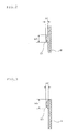
- FIG. 2 is an end view taken along the line B-B in FIG. 1(b) .
- the projection 21 provided on the inner surface of the side plate 2 serves to avoid contact of the adhesive layer exposed on the side surface of an adhesive tape 4 with the inner surface of the reel 1 (inner surface of the side plate 2) when winding up the adhesive tape 5 around the reel 1 or during the storage of the wound adhesive tape 5, whereby the adhesive constituting the adhesive layer is prevented from adhering to the inner surface of the reel 1.
- the distance between the side plates 2 and 2, which are separated by the wind-up unit 3, is set to be larger to some extent than the cut width of the adhesive tape 5 such that the adhesive tape 5 to be wound around the wind-up unit 3 is prevented from being adhered to the inner surface of the side plate 2. Even with this distance, if the winding position of the adhesive tape 5 is shifted due to irregular rotation or the like of the reel 1 during winding of the adhesive tape 5, or the position of the adhesive tape 5 which has been wound is shifted due to impact or vibration during storage, the adhesive tape 5 may come in contact with the inner surface of the side plate 2.
- the height hl of the projection 21 is preferably 0.05 to 1.00 mm, more preferably 0.05 to 0.30 mm, and particularly preferably 0.05 to 0.20 mm. If the height hl of the projection 21 is less than 0.05 mm, it may be hard to obtain the effects of suppressing contact of the adhesive tape 5 with the inner surface of the side plate 2. In addition, the height hl of less than 0.05 mm is not preferable, since the injection molding conditions of the reel 1 are required to be controlled accurately. On the other hand, if the height hl of the projection 21 exceeds 1.00 mm, the projection 21 becomes excessively high, affecting the width dimensions of the reel 1. In addition, this height is not preferable since pushing pressure to the side surface of the adhesive tape 5 increases, and as a result, the side surface of the adhesive tape 5 may acquire marks from the projection 21.
- the width w1 of the projection 21 is preferably 0.5 to 20.0 mm, more preferably 0.5 to 10.0 mm, and particularly preferably 0.5 to 5.0 mm. If the width w1 of the projections 21 is less than 0.5 mm, the side surface of the adhesive tape 5 may become damaged. In addition, the width w1 of the projection 21 of less than 0.5 mm is not preferable since the injection molding conditions of the reel 1 are required to be controlled accurately. On the other hand, when the width w1 of the projection 21 exceeds 20.0 mm, the adhesive may adhere to the projection 21.
- FIG. 3 is an end view showing the cross section taken along the line C-C in FIG. 1(b) .
- FIG. 4 is an explanatory view showing the winding-up state of the adhesive tape 5.
- FIG. 4(b) is a left side view of the state shown in FIG. 4(a) .
- the adhesive tape 5 is wound around the reel 1 which rotates in the direction shown by the arrow.
- the peripheral projection 22 provided on the inner surface along the peripheral part of the side plate 2 serves to prevent adherence of the adhesive constituting the adhesive layer to the peripheral part of the side plate 2, which is caused by the contact of the adhesive layer exposed on the side surface of the adhesive tape 5 with the peripheral part of the side plate 2 when winding the adhesive tape 5 around the reel 1 as mentioned above.
- the peripheral projection 22 extending in the circumference direction is provided on the inner surface along the peripheral part of the side plate 2 to suppress the adhesion of the adhesive.
- the peripheral projection 22 which is in contact with the adhesive tape 5 have a circular shape.
- the radius of curvature thereof is preferably 0.3 to 1.5 mm, more preferably 0.5 to 1.0 mm in order to reduce the contact area of the peripheral projection 21 with the adhesive tape 5.
- the height h2 of the peripheral projection 22 is preferably 0.05 to 1.00 mm, more preferably 0.05 to 0.30 mm, and particularly preferably 0.05 to 0.20 mm. If the height h2 of the peripheral projection 22 is less than 0.05 mm, the effects of suppressing contact of the adhesive tape 5 with the inner surface of the side plate 2 are impaired. In addition, such a small height of the peripheral projection 22 is not preferable since the adhesive tape 5 may become scratched due to interference of the projection 21 and the adhesive tape 5 when winding the adhesive tape 5.
- the peripheral projection 22 If the height h2 of the peripheral projection 22 exceeds 1.00 mm, the peripheral projection 22 becomes excessively high, and as a result, the peripheral projection 22 may interfere with the adhesive tape 5 when winding up the adhesive tape 5. In addition, since the gap between the wound adhesive tape 5 and the side plates 2 and 2 increases after winding of the adhesive tape 5 is completed, weaving may occur during storage, resulting in lowered storage stability.
- the width w2 of the peripheral projection 22 is preferably 0.5 to 20.0 mm, more preferably 0.5 to 10.0 mm, and particularly preferably 0.5 to 5.0 mm. If the width w2 of the peripheral projection 22 is less than 0.5 mm, the side surface of the adhesive tape 5 may become scratched. If the width w2 of the peripheral projection 22 exceeds 20.0 mm, the problem of adherence of the adhesive to the peripheral projection 22 occurs. In addition, when the adhesive tape 5 which has been wound up around the reel 1 is unwound for use, the adhesive tape 5 may become caught in the peripheral projection 22.
- both of the pair of side plates 2 and 2 are provided with the radially-directed projection 21 or the peripheral projection 22.
- the radially-directed projection 21 and the peripheral projection 22 may be provided on only one of the side plates 2 and 2. That is, if the adhesive tape 5 is wound near one of the side plates 2 in order to increase the distance between the other side plate 2 and the adhesive tape 5, the radially-directed projection 21'and the peripheral projection 22 can be provided on the one side plate 2.
- the shaft hole 4 in the shape of the letter D is shown.
- the shaft hole 4 may contain a key groove corresponding to a key provided on the winding shaft.
- the specific configuration of the shaft hole 4 can be changed corresponding to a means for mounting the winding apparatus to the winding shaft.
- the winding unit 3 may have various configurations which can be applied to this type of reel, for example, provision of a rib for ensuring rigidity.
- the adhesive tape 5 provided with an adhesive layer is used as an object to be wound.
- the reel of the invention can preferably be applied to an object to be wound provided with a sticky layer formed by applying a material generally known as a "sticky adhesive".
- the projections 21 provided on the inner surface of the side plate 2 are provided as a concave line formed continuously from the inner perimeter to the outer perimeter of the reel 1.
- the projections 21 may be formed intermittently.
- the projections 21 may be provided from the center of the side plate 2 to the periphery so that they extend in the radial direction.
- the projections 21 may be provided such that they intersect with the radial direction, and, as shown in FIG. 5(c) , the projections 21 may be provided in a spiral shape.
- the projections 21 are provided radially, the radial center thereof is preferably the same as the center of the side plate 2. However, it is possible to allow the radial center and the center of the side plate 2 to be different, if necessary. Furthermore, it is possible to form the projections 21 in such a manner that the projections 21 extend radially from each of these different radial centers.
- the shape of the cross section of the projection 21 is not limited to the above-mentioned circular shape.
- the cross section may have a rectangular shape or a rectangular shape with round corners, or the like.
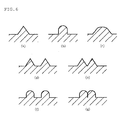
- the cross section may have a shape as shown in FIG. 6 .
- the peripheral projection 22 is provided along the entire circumference of the peripheral part of the side plate 2.
- the peripheral projection may be provided intermittently along the peripheral part of the side plate 2.
- the peripheral projection may be provided in a spiral form, and as shown in FIG. 7(c) , a plurality of (2 in the in the shown example) peripheral projections 22 may be arranged in parallel to each other.
- the peripheral projections 22 provided intermittently may be connected with the projections 21, which is provided to avoid adherence of the adhesive to the inner surface of the reel 1.
- the cross section of the peripheral projection 22 may have the same shape as that of the projection 21. Specifically, it may have a circular shape, a rectangular shape, a rectangular shape with round corners, or a shape shown in FIG. 6 .
- FIGs. 5 , 7 and 8 are explanatory views which conceptually show the positions of the projections 21 and 22 in the above-mentioned modification example.
- FIG. 6 is an explanatory view which shows the outline of the shape of the cross section of the projection 21 (or peripheral projection 22).
- FIGs. 6(d) and (f) show two projections 21 (or peripheral projections 22) which are arranged in parallel in such a manner that they are close to each other
- FIGs. 6(e) and (g) show two projections 21 (or peripheral projections 22) which are arranged in such a manner that they are in contact with each other.
- the invention provides a reel used to manufacture and supply an adhesive tape, which prevents adherence of an adhesive to the inner surface thereof.
Landscapes
- Storage Of Web-Like Or Filamentary Materials (AREA)
- Adhesive Tapes (AREA)
Abstract
Description
- The invention relates to a reel for winding an adhesive tape (a sticky tape) obtained by cutting into a narrow tape a film material on which an adhesive layer (or a sticky layer) is formed.
- In recent years, an anisotropic conductive film obtained by incorporating conductive fine particles into an adhesive layer formed on a substrate is widely used in circuit connection of liquid crystal displays. Generally, as stated in
Patent Document 1 or the like, this type of anisotropic conductive file' is manufactured and supplied by a method in which an adhesive layer is formed by coating or the like on a wide film material and the resultant is cut into a narrow tape. -
- Patent Document 1:
JP-A-2003-34468 - The inventors made extensive studies. As a result, the inventors have found that, in producing an anisotropic conductive film, there is yet room for improvement in the production method in which a film material on which an adhesive layer is formed by coating is wound around a reel while cutting it into a narrow tape. Specifically, during winding around a reel or during storage of the wound tape, an adhesive forming the adhesive layer tends to adhere to the inner surface of the reel, resulting in formation of defective products.
- The invention has been made based on the above-mentioned studies by the inventors. An object of the invention, in manufacturing and supplying an adhesive film (tape) such as an anisotropic conductive film by a method in which a film material on which an adhesive layer is formed by coating is wound around a reel while cutting it into a narrow tape, is to provide a reel which can prevent adherence of an adhesive to the inner surface of the reel to improve yield, as well as ensure stable unwinding of the adhesive tape for use.
- The reel of the invention, which solves the above-mentioned problem, comprises a columnar wind-up unit and a pair of opposing side plates provided such that the wind-up unit is between the side plates, wherein the inner surface of one or both of the side plates is provided with a projection which extends continuously or intermittently.
- The reel of the invention with the above-mentioned configuration has a novel shape which cannot be found in conventional reels. If adhesive tapes are manufactured and supplied by a method in which a film material on which an adhesive layer is formed by coating is wound up around the reel of the invention while cutting it into a narrow tape, it is possible to prevent an adhesive constituting the adhesive layer from adhering to the inner surface of the reel during manufacturing or storage after winding.
- The reel of the invention can be configured such that the above-mentioned projection extends in the radial direction. In this case, it is preferred that the reel have a configuration in which the above-mentioned projections are provided radially.
By this configuration, adherence of an adhesive constituting the adhesive layer to the inner surface of a reel can be prevented more consistently. - In the reel of the invention, in order to further ensure prevention of adherence of an adhesive to the inner surface of a reel without causing problems, it is preferred that the above-mentioned radially-directed projection be 0.05 to 1.00 mm in height and 0.5 to 20.0 mm in width.
- The reel according to the invention may have a configuration in which a peripheral projection extending in the circumferential direction thereof is provided on the inner surface along the peripheral part of one or both of the above-mentioned side plates.
Due to such a configuration, when the adhesive tape is wound while preventing un-uniform winding by guiding the side surface of the adhesive tape, which is the object being wound, with the peripheral part of the side plate, it is possible to reduce the area of the adhesive tape in contact with the peripheral part, whereby adherence of the adhesive to the peripheral part of the side plate can be prevented. - In the reel of the invention, in order to reduce the area of the adhesive tape in contact with the peripheral part, which is the object being wound, when winding the adhesive tape while guiding the side surface thereof with the peripheral part of the side plate, it is preferred that at least part of the peripheral projection which is in contact with the object be circular in shape.
- In the reel of the invention, in order to further ensure prevention of adherence of an adhesive to the peripheral part of the side plates, it is preferred that the projection be 0.05 to 1.00 mm in height and 0.5 to 20.0 mm in width.
- In the reel of the invention, the object being wound can be provided with an adhesive layer or a sticky layer. The reel of the invention can preferably be applied to the object being wound, which is provided with a sticky layer formed by applying a material generally known as a "sticky adhesive", and thus adherence of a sticky adhesive can be prevented.
- According to the invention, when winding a film material on which an adhesive layer or a sticky layer is formed by coating around a reel while cutting it into a narrow tape, or during storage of the wound tape, it is possible to prevent adherence of an adhesive or sticky adhesive to the inner surface of the reel, thereby improving yield by eliminating formation of defective products.
-
-
FIG. 1 is a view illustrating an embodiment of the reel of the invention; -
FIG. 2 is an end view taken along the line B-B ofFIG. 1(b) ; -
FIG. 3 is an end view taken along the line C-C ofFIG. 1(b) ; -
FIG. 4 is an explanatory view showing the winding state of the adhesive tape; -
FIG. 5 is a conceptual view showing the position of the projection on the inner surface of the side plate according to a modification example of the reel of the invention; -
FIG. 6 is an explanatory view showing the outline of the cross section of the projection provided on the inner surface of the side plate or the peripheral projection provided on the inner surface along the peripheral part of the side plate according to a modification example of the reel of the invention; -
FIG. 7 is a conceptual view showing the position of the peripheral projection provided on the inner surface along the peripheral part of the side plate according to a modification example of the reel of the invention; and -
FIG. 8 is a conceptual view showing the positions of the projections provided on the inner surface of the side plate and the peripheral projections provided on the inner surface along the peripheral part of the side plate according to a modification example of the reel of the invention. - The preferred embodiments of the invention will be described with reference to the drawings.
FIG. 1 is an explanatory view showing the outline of the reel according to the invention, in whichFIG. 1(a) is a front view andFIG. 1(b) is a cross sectional view ofFIG. 1(a) taken along the line A-A inFIG. 1(a) . - A
reel 1 shown inFIG. 1 is provided with a columnar wind-upunit 3 and a pair ofside plates unit 3 is between the side plates. A D-shaped shaft hole 4 penetrates through almost the center of thereel 1. By inserting the wind-up shaft of a wind-up apparatus (not shown) into thisshaft hole 4, thereel 1 is installed on this wind-up apparatus, and the reel is allowed to rotate when the wind-up shaft is driven. - The
reel 1 with such a configuration is used for manufacturing and supplying variousadhesive tapes 5 by a method in which a film material on which an adhesive layer is formed by coating is cut into a narrow tape and the narrow tape is wound around the reel. The width of the wind-upunit 3, namely the distance between theside plates unit 3 can be appropriately set according to the cut width of anadhesive tape 5 as the object being wound. In addition, theside plate 2 is normally formed in a circular shape, and the diameter thereof can be appropriately set according to the winding length of theadhesive tape 5. - In this embodiment, the
reel 1 may be a reel which is integrally formed by injection molding or the like. However, the pair of theside plates unit 3 may be formed separately, and these parts may be connected by an appropriate means such as fitting and adhesion. By forming theside plates unit 3 separately, the following configuration can be realized. For example, theside plates 2 differing in diameter can be combined with the common wind-upunit 3, thereby allowing thereel 1 to correspond to various winding lengths, or the wind-upunits 3 differing in width can be combined with thecommon side plate 2, thereby allowing the reel to correspond to various cutting widths. - In this embodiment, as shown in
FIG. 1 (b) andFIG. 2 , aprojection 21 extending in the radial direction is provided on the inner surface of theside plates
FIG. 2 is an end view taken along the line B-B inFIG. 1(b) . - The
projection 21 provided on the inner surface of theside plate 2 serves to avoid contact of the adhesive layer exposed on the side surface of anadhesive tape 4 with the inner surface of the reel 1 (inner surface of the side plate 2) when winding up theadhesive tape 5 around thereel 1 or during the storage of the woundadhesive tape 5, whereby the adhesive constituting the adhesive layer is prevented from adhering to the inner surface of thereel 1. - That is, the distance between the
side plates unit 3, is set to be larger to some extent than the cut width of theadhesive tape 5 such that theadhesive tape 5 to be wound around the wind-upunit 3 is prevented from being adhered to the inner surface of theside plate 2. Even with this distance, if the winding position of theadhesive tape 5 is shifted due to irregular rotation or the like of thereel 1 during winding of theadhesive tape 5, or the position of theadhesive tape 5 which has been wound is shifted due to impact or vibration during storage, theadhesive tape 5 may come in contact with the inner surface of theside plate 2.
In this embodiment, even in such a case, by providing aprojection 21 on the inner surface of theside plate 2, the contact area of the adhesive layer exposed on the side surface of theadhesive tape 5 and the inner surface of theside plate 2 can be reduced, whereby adherence of the adhesive constituting the adhesive layer to the inner surface of thereel 1 can be prevented. - In this embodiment, when
such projection 21 is provided, the height hl of theprojection 21 is preferably 0.05 to 1.00 mm, more preferably 0.05 to 0.30 mm, and particularly preferably 0.05 to 0.20 mm.
If the height hl of theprojection 21 is less than 0.05 mm, it may be hard to obtain the effects of suppressing contact of theadhesive tape 5 with the inner surface of theside plate 2. In addition, the height hl of less than 0.05 mm is not preferable, since the injection molding conditions of thereel 1 are required to be controlled accurately. On the other hand, if the height hl of theprojection 21 exceeds 1.00 mm, theprojection 21 becomes excessively high, affecting the width dimensions of thereel 1. In addition, this height is not preferable since pushing pressure to the side surface of theadhesive tape 5 increases, and as a result, the side surface of theadhesive tape 5 may acquire marks from theprojection 21. - The width w1 of the
projection 21 is preferably 0.5 to 20.0 mm, more preferably 0.5 to 10.0 mm, and particularly preferably 0.5 to 5.0 mm.
If the width w1 of theprojections 21 is less than 0.5 mm, the side surface of theadhesive tape 5 may become damaged. In addition, the width w1 of theprojection 21 of less than 0.5 mm is not preferable since the injection molding conditions of thereel 1 are required to be controlled accurately. On the other hand, when the width w1 of theprojection 21 exceeds 20.0 mm, the adhesive may adhere to theprojection 21. - In this embodiment, as shown in
FIG. 1 , radial provision of a plurality of (8 in the shown example)projections 21 which extend in the radial direction is preferable, since adherence of the adhesive constituting the adhesive layer to the inner surface of thereel 1 can be prevented more surely. - In this embodiment, on the inner surface along the peripheral part of the
side plate 2, theperipheral projection 22 extending in the circumference direction are provided as shown inFIG. 1(b) andFIG. 3 .
FIG. 3 is an end view showing the cross section taken along the line C-C inFIG. 1(b) . - When winding the
adhesive tape 5 around thereel 1, which has been cut to have a narrow width, as shown inFIG. 4(a) , if theadhesive tape 5 is slightly tilted and the side surface of theadhesive tape 5 is guided by the peripheral part of theside plate 2, theadhesive tape 5 can be wound uniformly with flushed stacked side surfaces of the woundadhesive tape 5.
FIG. 4 is an explanatory view showing the winding-up state of theadhesive tape 5.FIG. 4(b) is a left side view of the state shown inFIG. 4(a) . In this figure, theadhesive tape 5 is wound around thereel 1 which rotates in the direction shown by the arrow. - In this embodiment, the
peripheral projection 22 provided on the inner surface along the peripheral part of theside plate 2 serves to prevent adherence of the adhesive constituting the adhesive layer to the peripheral part of theside plate 2, which is caused by the contact of the adhesive layer exposed on the side surface of theadhesive tape 5 with the peripheral part of theside plate 2 when winding theadhesive tape 5 around thereel 1 as mentioned above. - That is, in this embodiment, when guiding the side surface of the
adhesive tape 5 with the peripheral part of theside plate 2, in order to reduce the contact area with theadhesive tape 5, theperipheral projection 22 extending in the circumference direction is provided on the inner surface along the peripheral part of theside plate 2 to suppress the adhesion of the adhesive. - Therefore, it is preferred that at least part of the
peripheral projection 22 which is in contact with theadhesive tape 5 have a circular shape. The radius of curvature thereof is preferably 0.3 to 1.5 mm, more preferably 0.5 to 1.0 mm in order to reduce the contact area of theperipheral projection 21 with theadhesive tape 5. - In this embodiment, in providing such
peripheral projection 22, the height h2 of theperipheral projection 22 is preferably 0.05 to 1.00 mm, more preferably 0.05 to 0.30 mm, and particularly preferably 0.05 to 0.20 mm.
If the height h2 of theperipheral projection 22 is less than 0.05 mm, the effects of suppressing contact of theadhesive tape 5 with the inner surface of theside plate 2 are impaired. In addition, such a small height of theperipheral projection 22 is not preferable since theadhesive tape 5 may become scratched due to interference of theprojection 21 and theadhesive tape 5 when winding theadhesive tape 5. If the height h2 of theperipheral projection 22 exceeds 1.00 mm, theperipheral projection 22 becomes excessively high, and as a result, theperipheral projection 22 may interfere with theadhesive tape 5 when winding up theadhesive tape 5. In addition, since the gap between the woundadhesive tape 5 and theside plates adhesive tape 5 is completed, weaving may occur during storage, resulting in lowered storage stability. - The width w2 of the
peripheral projection 22 is preferably 0.5 to 20.0 mm, more preferably 0.5 to 10.0 mm, and particularly preferably 0.5 to 5.0 mm.
If the width w2 of theperipheral projection 22 is less than 0.5 mm, the side surface of theadhesive tape 5 may become scratched. If the width w2 of theperipheral projection 22 exceeds 20.0 mm, the problem of adherence of the adhesive to theperipheral projection 22 occurs. In addition, when theadhesive tape 5 which has been wound up around thereel 1 is unwound for use, theadhesive tape 5 may become caught in theperipheral projection 22. - The preferred embodiments of the invention have been described hereinabove. The invention is not limited to the embodiments mentioned above, and it is needless to say that various modifications are possible within the scope of the invention.
- For example, in the above-mentioned embodiments, both of the pair of
side plates projection 21 or theperipheral projection 22. However, if necessary, the radially-directedprojection 21 and theperipheral projection 22 may be provided on only one of theside plates
That is, if theadhesive tape 5 is wound near one of theside plates 2 in order to increase the distance between theother side plate 2 and theadhesive tape 5, the radially-directed projection 21'and theperipheral projection 22 can be provided on the oneside plate 2. - In the above embodiment, the
shaft hole 4 in the shape of the letter D is shown. However, theshaft hole 4 may contain a key groove corresponding to a key provided on the winding shaft. The specific configuration of theshaft hole 4 can be changed corresponding to a means for mounting the winding apparatus to the winding shaft. - In the above-mentioned embodiment, the configuration of the winding
unit 3 is roughly shown. The windingunit 3 may have various configurations which can be applied to this type of reel, for example, provision of a rib for ensuring rigidity. - In the above-mentioned embodiment, the
adhesive tape 5 provided with an adhesive layer is used as an object to be wound. However, the reel of the invention can preferably be applied to an object to be wound provided with a sticky layer formed by applying a material generally known as a "sticky adhesive". - In the above-mentioned embodiment, the
projections 21 provided on the inner surface of theside plate 2 are provided as a concave line formed continuously from the inner perimeter to the outer perimeter of thereel 1. However, as shown inFIG. 5(a) , theprojections 21 may be formed intermittently. Furthermore, theprojections 21 may be provided from the center of theside plate 2 to the periphery so that they extend in the radial direction. In addition, as shown inFIG. 5(b) , theprojections 21 may be provided such that they intersect with the radial direction, and, as shown inFIG. 5(c) , theprojections 21 may be provided in a spiral shape.
If theprojections 21 are provided radially, the radial center thereof is preferably the same as the center of theside plate 2. However, it is possible to allow the radial center and the center of theside plate 2 to be different, if necessary. Furthermore, it is possible to form theprojections 21 in such a manner that theprojections 21 extend radially from each of these different radial centers. - Furthermore, the shape of the cross section of the
projection 21 is not limited to the above-mentioned circular shape. The cross section may have a rectangular shape or a rectangular shape with round corners, or the like. The cross section may have a shape as shown inFIG. 6 . - As mentioned above, there are no specific limitations on specific aspects, e.g. the number or shape of the
projection 21 provided on the inner surface of theside plate 2, insofar as adherence of the adhesive to the inner surface of thereel 1 can be prevented. - As in the case of the
peripheral projection 22 provided along the peripheral part of theside plate 2, various modifications are possible, as long as adherence of the adhesive can be prevented when winding is performed while guiding the side surface of theadhesive tape 5 with the peripheral part of theside plate 2.
In the above-mentioned embodiment, theperipheral projection 22 is provided along the entire circumference of the peripheral part of theside plate 2. However, as shown inFIG. 7(a) , the peripheral projection may be provided intermittently along the peripheral part of theside plate 2. In addition; as shown inFIG. 7 (b) , the peripheral projection may be provided in a spiral form, and as shown inFIG. 7(c) , a plurality of (2 in the in the shown example)peripheral projections 22 may be arranged in parallel to each other.
Furthermore, as shown inFIGs. 8(a) to (c) , theperipheral projections 22 provided intermittently may be connected with theprojections 21, which is provided to avoid adherence of the adhesive to the inner surface of thereel 1. - The cross section of the
peripheral projection 22 may have the same shape as that of theprojection 21. Specifically, it may have a circular shape, a rectangular shape, a rectangular shape with round corners, or a shape shown inFIG. 6 . - Here,
FIGs. 5 ,7 and8 are explanatory views which conceptually show the positions of theprojections FIG. 6 is an explanatory view which shows the outline of the shape of the cross section of the projection 21 (or peripheral projection 22).FIGs. 6(d) and (f) show two projections 21 (or peripheral projections 22) which are arranged in parallel in such a manner that they are close to each other, andFIGs. 6(e) and (g) show two projections 21 (or peripheral projections 22) which are arranged in such a manner that they are in contact with each other. - As mentioned hereinabove, the invention provides a reel used to manufacture and supply an adhesive tape, which prevents adherence of an adhesive to the inner surface thereof.
- A. A reel comprising a columnar wind-up unit and a pair of opposing side plates provided such that the wind-up unit is between the side plates, wherein the inner surface of one or both of the side plates is provided with a projection which extends continuously or intermittently.
- B. The reel according to A, wherein the projection is provided such that it extends in the radial direction.
- C. The reel according to B, wherein projections are provided radially.
- D. The reel according to any one of A. to C., wherein the height of the projection is 0.05 to 1.00 mm.
- E. The reel according to any one of A. to D., wherein the width of the projection is 0.5 to 20.0 mm.
- F. The reel according to any one of A. to E., wherein peripheral projection is provided along the peripheral part on the inner surface of one or both of the side plates.
- G. The reel according to F., wherein at least part of the peripheral projection which is in contact with an object to be wound when the object is wound while guiding the side surface of the object by the peripheral part of the side plate has a circular shape.
- H. The reel according to any one of F. to G., wherein the height, of the peripheral projection is 0.05 to 1.00 mm.
- I. The reel according to any one of F. to H., wherein the width of the peripheral projection is 0.5 to 20.0 mm.
- J. The reel according to any one of A. to I., wherein the object to be wound is provided with an adhesive layer or a sticky layer.
- K. A reel comprising a columnar wind-up unit, and a pair of opposing side plates provided such that the wind-up unit is between the plates and a D-shaped shaft hole.
Claims (10)
- A method of preventing an adhesive or a sticky adhesive constituting an adhesive layer or a sticky layer that an object being wound has from adhering to a inner surface of a reel, wherein the object being wound which is an adhesive tape provided with an adhesive layer or the sticky tape provided with a sticky layer is wound up around the reel which comprising a columnar wind-up unit and a pair of opposing side plates provided such that the wind-up unit is between the side plates, and the inner surface of one or both of the side plates is provided with a projection which extends continuously or intermittently along the radial direction.
- The method of preventing an adhesive or a sticky adhesive constituting an adhesive layer or a sticky layer that an object being wound has from adhering to an inner surface of a reel according to claim 1, wherein the object being wound is an adhesive tape provided with an adhesive layer.
- The method of preventing an adhesive or a sticky adhesive constituting an adhesive layer or a sticky layer that an object being wound has from adhering to an inner surface of a reel according to claim 2, wherein the adhesive tape is obtained by cutting into a narrow tape an anisotropic conductive film obtained by incorporating conductive particles into an adhesive layer formed on a substrate.
- The method of preventing an adhesive or a sticky adhesive constituting an adhesive layer or a sticky layer that an object being wound has from adhering to an inner surface of a reel according to any one of claims 1 to 3, wherein projections are provided radially.
- The method of preventing an adhesive or a sticky adhesive constituting an adhesive layer or a sticky layer that an object being wound has from adhering to an inner surface of a reel according to any one of claims 1 to 4, wherein the height of the projection is 0.05 to 1.00 mm.
- The method of preventing an adhesive or a sticky adhesive constituting an adhesive layer or a sticky layer that an object being wound has from adhering to a inner surface of a reel according to any one of claims 1 to 5, wherein the width of the projection is 0.5 to 20.0 mm.
- The method of preventing an adhesive or a sticky adhesive constituting an adhesive layer or a sticky layer that an object being wound has from adhering to an inner surface of a reel according to any one of claims 1 to 6, wherein the reel provided with a peripheral projection along the periphery on the inner surface of one or both of the side plates.
- The method of preventing an adhesive or a sticky adhesive constituting an adhesive layer or a sticky layer that an object being wound has from adhering to a inner surface of a reel according to claim 7, wherein at least part of the peripheral projection which is in contact with the object being wound has a circular shape when the object being wound is wound while guiding the side surface of the object by the periphery of the side plates.
- The method of preventing an adhesive or a sticky adhesive constituting an adhesive layer or a sticky layer that an object being wound has from adhering to a inner surface of a reel according to any one of claims 7 to 8, wherein the height of the peripheral projection is 0.05 to 1.00 mm.
- The method of preventing an adhesive or a sticky adhesive constituting an adhesive layer or a sticky layer that an object being wound has from adhering to an inner surface of a reel according to any one of claims 7 to 9, wherein the width of the peripheral projection is 0.5 to 20.0 mm.
Applications Claiming Priority (2)
| Application Number | Priority Date | Filing Date | Title |
|---|---|---|---|
| JP2006170961 | 2006-06-21 | ||
| EP07745221A EP2030936A4 (en) | 2006-06-21 | 2007-06-14 | Reel |
Related Parent Applications (1)
| Application Number | Title | Priority Date | Filing Date |
|---|---|---|---|
| EP07745221.7 Division | 2007-06-14 |
Publications (2)
| Publication Number | Publication Date |
|---|---|
| EP2368828A2 true EP2368828A2 (en) | 2011-09-28 |
| EP2368828A3 EP2368828A3 (en) | 2011-12-21 |
Family
ID=38833335
Family Applications (3)
| Application Number | Title | Priority Date | Filing Date |
|---|---|---|---|
| EP11169468A Withdrawn EP2368828A3 (en) | 2006-06-21 | 2007-06-14 | Reel |
| EP11169467A Withdrawn EP2364944A3 (en) | 2006-06-21 | 2007-06-14 | Tape roll |
| EP07745221A Withdrawn EP2030936A4 (en) | 2006-06-21 | 2007-06-14 | Reel |
Family Applications After (2)
| Application Number | Title | Priority Date | Filing Date |
|---|---|---|---|
| EP11169467A Withdrawn EP2364944A3 (en) | 2006-06-21 | 2007-06-14 | Tape roll |
| EP07745221A Withdrawn EP2030936A4 (en) | 2006-06-21 | 2007-06-14 | Reel |
Country Status (7)
| Country | Link |
|---|---|
| US (3) | US20090230233A1 (en) |
| EP (3) | EP2368828A3 (en) |
| JP (4) | JPWO2007148593A1 (en) |
| KR (1) | KR101330861B1 (en) |
| CN (3) | CN102085983B (en) |
| TW (3) | TW200825011A (en) |
| WO (1) | WO2007148593A1 (en) |
Families Citing this family (16)
| Publication number | Priority date | Publication date | Assignee | Title |
|---|---|---|---|---|
| CN103003178B (en) * | 2010-03-23 | 2015-09-30 | 日立化成株式会社 | Adhesive tape reel |
| WO2013008744A1 (en) * | 2011-07-08 | 2013-01-17 | 日立化成工業株式会社 | Reel for adhesive tape, tape roll, packaging, use of reel as reel for adhesive tape for winding adhesive tape, and method for manufacturing reel for adhesive tape |
| JP5930274B2 (en) * | 2011-12-05 | 2016-06-08 | デクセリアルズ株式会社 | Reel member and film container |
| JP5982158B2 (en) * | 2012-04-06 | 2016-08-31 | デクセリアルズ株式会社 | Reel member |
| JP5982159B2 (en) * | 2012-04-06 | 2016-08-31 | デクセリアルズ株式会社 | Reel member, adhesive film winding method, adhesive film unwinding method |
| JP5939504B2 (en) * | 2012-05-02 | 2016-06-22 | ブラザー工業株式会社 | Tape winding device and core member |
| JP5905351B2 (en) * | 2012-07-04 | 2016-04-20 | デクセリアルズ株式会社 | Reel member and film container |
| JP6197395B2 (en) * | 2012-07-20 | 2017-09-20 | 日立化成株式会社 | Reel and tape for adhesive tape |
| JP6202033B2 (en) * | 2014-05-15 | 2017-09-27 | 株式会社村田製作所 | Taping electronic component continuous reel and manufacturing method thereof |
| KR20190035956A (en) * | 2015-02-27 | 2019-04-03 | 데쿠세리아루즈 가부시키가이샤 | Reel body, film connection body, film winding body, and manufacturing method for film connection body |
| CN106364989A (en) * | 2015-07-21 | 2017-02-01 | 刘程秀 | Supporting body of belt-shaped object |
| JP6905320B2 (en) * | 2016-09-27 | 2021-07-21 | デクセリアルズ株式会社 | Adhesive film winding body, manufacturing method of adhesive film winding body |
| TWI767131B (en) | 2018-07-18 | 2022-06-11 | 日商美克司股份有限公司 | strapping belt |
| JP7325706B2 (en) * | 2018-07-18 | 2023-08-15 | マックス株式会社 | Binding tape, binding method, tape wound body and reel |
| JP7595411B2 (en) * | 2019-11-22 | 2024-12-06 | デクセリアルズ株式会社 | Reel parts, adhesive film rolls |
| US20240299856A1 (en) * | 2023-03-10 | 2024-09-12 | Nelson Companies One, LLC | Balloon weight and ribbon assembly with adhesive film peel-assist feature |
Citations (1)
| Publication number | Priority date | Publication date | Assignee | Title |
|---|---|---|---|---|
| JP2003034468A (en) | 2001-02-16 | 2003-02-07 | Sony Chem Corp | Reel member and film winding method |
Family Cites Families (30)
| Publication number | Priority date | Publication date | Assignee | Title |
|---|---|---|---|---|
| US1951151A (en) * | 1933-07-21 | 1934-03-13 | Metal Package Corp | Tape spool |
| GB869979A (en) * | 1959-02-17 | 1961-06-07 | Hallmark Cards | Improvements in or relating to spools for decorative or other ribbon |
| US2973159A (en) * | 1959-08-17 | 1961-02-28 | Thomas S Kulka | Friction reducing tape reel |
| US3099414A (en) * | 1961-02-27 | 1963-07-30 | Thomas S Kuika | Tape reel having friction reducing means |
| FR1313449A (en) * | 1962-01-23 | 1962-12-28 | Plastic ring | |
| US3342435A (en) * | 1966-04-11 | 1967-09-19 | Data Packaging Corp | Reel with tape guide |
| JPS5443246Y2 (en) * | 1971-05-11 | 1979-12-14 | ||
| JPS5647175Y2 (en) * | 1976-10-27 | 1981-11-05 | ||
| JPS5363379A (en) * | 1976-11-17 | 1978-06-06 | Nippon Kayaku Co Ltd | Preparation of 2-phenylbenzotriazoles or their n-oxides |
| JPS56135965U (en) * | 1980-03-17 | 1981-10-15 | ||
| JPS56140557U (en) * | 1980-03-19 | 1981-10-23 | ||
| JPS56135965A (en) * | 1980-03-28 | 1981-10-23 | Nec Corp | Semiconductor device |
| JPS56140557A (en) * | 1980-04-04 | 1981-11-02 | Pioneer Electronic Corp | Bookshelf type record player |
| USD298541S (en) * | 1985-12-17 | 1988-11-15 | Strapack Corporation | Reel plate for a strapping machine |
| US4726534A (en) * | 1986-08-06 | 1988-02-23 | Advantek Inc. | Convertible reel assembly |
| JPS6490763A (en) * | 1987-10-01 | 1989-04-07 | Seiko Epson Corp | Wire dot head |
| JPH0190763U (en) * | 1987-12-07 | 1989-06-14 | ||
| JP2570366Y2 (en) * | 1993-01-29 | 1998-05-06 | 信越ポリマー株式会社 | Carrier tape reel |
| US5474254A (en) * | 1994-11-08 | 1995-12-12 | Faulkner Fabricators, Inc. | Spool and method of making same |
| USD370908S (en) * | 1995-09-08 | 1996-06-18 | Alpha Enterprises, Inc. | Tape reel flange |
| JPH09278291A (en) * | 1996-04-16 | 1997-10-28 | Toshiba Corp | Tape take-up reel |
| US6196495B1 (en) * | 1996-05-30 | 2001-03-06 | Kolon Industries, Inc. | Reel for winding photosensitive film |
| US6598825B2 (en) * | 1998-02-13 | 2003-07-29 | C. Robert Ripplinger | Simultaneous-access surfaces for reel-flange fasteners |
| JP3945076B2 (en) | 1999-06-30 | 2007-07-18 | ブラザー工業株式会社 | Tape cassette |
| DE29918667U1 (en) * | 1999-10-22 | 1999-12-30 | BIC Deutschland GmbH & Co, 65835 Liederbach | Handheld device for transferring a film from a carrier tape to a substrate, with a backstop |
| US6435451B1 (en) * | 2000-10-19 | 2002-08-20 | Storage Technology Corporation | Compliant tape reel flanges |
| JP2003031990A (en) * | 2001-07-11 | 2003-01-31 | Sanyo Electric Co Ltd | Parts supply device |
| US7073742B2 (en) * | 2003-01-21 | 2006-07-11 | Quantum Corporation | Tape guiding reel |
| US20040140392A1 (en) * | 2003-01-21 | 2004-07-22 | George Saliba | Butterfly tape reel |
| CN101472821A (en) * | 2006-06-21 | 2009-07-01 | 日立化成工业株式会社 | reel |
-
2007
- 2007-06-14 CN CN2011100252808A patent/CN102085983B/en active Active
- 2007-06-14 CN CN2011100252916A patent/CN102107803A/en active Pending
- 2007-06-14 WO PCT/JP2007/061964 patent/WO2007148593A1/en not_active Ceased
- 2007-06-14 US US12/306,250 patent/US20090230233A1/en not_active Abandoned
- 2007-06-14 EP EP11169468A patent/EP2368828A3/en not_active Withdrawn
- 2007-06-14 EP EP11169467A patent/EP2364944A3/en not_active Withdrawn
- 2007-06-14 JP JP2008522411A patent/JPWO2007148593A1/en active Pending
- 2007-06-14 EP EP07745221A patent/EP2030936A4/en not_active Withdrawn
- 2007-06-14 KR KR1020087030993A patent/KR101330861B1/en active Active
- 2007-06-14 CN CNA2007800228590A patent/CN101479176A/en active Pending
- 2007-06-21 TW TW096122289A patent/TW200825011A/en unknown
- 2007-06-21 TW TW099139965A patent/TW201125803A/en unknown
- 2007-06-21 TW TW099139967A patent/TW201125804A/en not_active IP Right Cessation
-
2010
- 2010-11-01 JP JP2010245529A patent/JP5024444B2/en active Active
- 2010-12-01 JP JP2010268264A patent/JP2011089126A/en active Pending
-
2011
- 2011-02-22 US US13/032,615 patent/US20110139916A1/en not_active Abandoned
- 2011-02-22 US US13/032,599 patent/US20110139922A1/en not_active Abandoned
- 2011-12-20 JP JP2011278716A patent/JP5293802B2/en active Active
Patent Citations (1)
| Publication number | Priority date | Publication date | Assignee | Title |
|---|---|---|---|---|
| JP2003034468A (en) | 2001-02-16 | 2003-02-07 | Sony Chem Corp | Reel member and film winding method |
Also Published As
| Publication number | Publication date |
|---|---|
| JP2011020859A (en) | 2011-02-03 |
| EP2030936A4 (en) | 2010-12-22 |
| CN102085983B (en) | 2013-05-01 |
| KR101330861B1 (en) | 2013-11-18 |
| TW201125803A (en) | 2011-08-01 |
| JP5024444B2 (en) | 2012-09-12 |
| JP2012057176A (en) | 2012-03-22 |
| EP2030936A1 (en) | 2009-03-04 |
| EP2364944A2 (en) | 2011-09-14 |
| JP2011089126A (en) | 2011-05-06 |
| TWI360510B (en) | 2012-03-21 |
| WO2007148593A1 (en) | 2007-12-27 |
| KR20090018831A (en) | 2009-02-23 |
| CN102107803A (en) | 2011-06-29 |
| CN101479176A (en) | 2009-07-08 |
| US20110139916A1 (en) | 2011-06-16 |
| CN102085983A (en) | 2011-06-08 |
| JP5293802B2 (en) | 2013-09-18 |
| US20090230233A1 (en) | 2009-09-17 |
| JPWO2007148593A1 (en) | 2009-11-19 |
| US20110139922A1 (en) | 2011-06-16 |
| TWI360511B (en) | 2012-03-21 |
| TW200825011A (en) | 2008-06-16 |
| EP2364944A3 (en) | 2011-12-21 |
| EP2368828A3 (en) | 2011-12-21 |
| TW201125804A (en) | 2011-08-01 |
Similar Documents
| Publication | Publication Date | Title |
|---|---|---|
| EP2364944A2 (en) | Tape roll | |
| US20110198433A1 (en) | Reel | |
| CN103958384B (en) | Reel parts and film housing | |
| KR101467128B1 (en) | Winding core, winding reel and band-winding method | |
| JP2009286046A (en) | Cartridge for change of coating film transfer tool, and main body case | |
| JP2009149397A (en) | Reel for adhesive tape | |
| JP2019005926A (en) | Coating film transfer tool | |
| JP5050832B2 (en) | Reel for adhesive tape | |
| JP5835905B2 (en) | Roll manufacturing method |
Legal Events
| Date | Code | Title | Description |
|---|---|---|---|
| PUAI | Public reference made under article 153(3) epc to a published international application that has entered the european phase |
Free format text: ORIGINAL CODE: 0009012 |
|
| 17P | Request for examination filed |
Effective date: 20110610 |
|
| AC | Divisional application: reference to earlier application |
Ref document number: 2030936 Country of ref document: EP Kind code of ref document: P |
|
| AK | Designated contracting states |
Kind code of ref document: A2 Designated state(s): AT BE BG CH CY CZ DE DK EE ES FI FR GB GR HU IE IS IT LI LT LU LV MC MT NL PL PT RO SE SI SK TR |
|
| AX | Request for extension of the european patent |
Extension state: AL BA HR MK RS |
|
| PUAL | Search report despatched |
Free format text: ORIGINAL CODE: 0009013 |
|
| AK | Designated contracting states |
Kind code of ref document: A3 Designated state(s): AT BE BG CH CY CZ DE DK EE ES FI FR GB GR HU IE IS IT LI LT LU LV MC MT NL PL PT RO SE SI SK TR |
|
| AX | Request for extension of the european patent |
Extension state: AL BA HR MK RS |
|
| RIC1 | Information provided on ipc code assigned before grant |
Ipc: B65H 75/14 20060101AFI20111118BHEP |
|
| STAA | Information on the status of an ep patent application or granted ep patent |
Free format text: STATUS: THE APPLICATION HAS BEEN WITHDRAWN |
|
| 18W | Application withdrawn |
Effective date: 20120121 |