EP2368806A1 - Boîte de pliage - Google Patents
Boîte de pliage Download PDFInfo
- Publication number
- EP2368806A1 EP2368806A1 EP10157390A EP10157390A EP2368806A1 EP 2368806 A1 EP2368806 A1 EP 2368806A1 EP 10157390 A EP10157390 A EP 10157390A EP 10157390 A EP10157390 A EP 10157390A EP 2368806 A1 EP2368806 A1 EP 2368806A1
- Authority
- EP
- European Patent Office
- Prior art keywords
- box part
- wall
- bottom wall
- outer box
- side walls
- Prior art date
- Legal status (The legal status is an assumption and is not a legal conclusion. Google has not performed a legal analysis and makes no representation as to the accuracy of the status listed.)
- Ceased
Links
Images


Classifications
-
- B—PERFORMING OPERATIONS; TRANSPORTING
- B65—CONVEYING; PACKING; STORING; HANDLING THIN OR FILAMENTARY MATERIAL
- B65D—CONTAINERS FOR STORAGE OR TRANSPORT OF ARTICLES OR MATERIALS, e.g. BAGS, BARRELS, BOTTLES, BOXES, CANS, CARTONS, CRATES, DRUMS, JARS, TANKS, HOPPERS, FORWARDING CONTAINERS; ACCESSORIES, CLOSURES, OR FITTINGS THEREFOR; PACKAGING ELEMENTS; PACKAGES
- B65D5/00—Rigid or semi-rigid containers of polygonal cross-section, e.g. boxes, cartons or trays, formed by folding or erecting one or more blanks made of paper
- B65D5/42—Details of containers or of foldable or erectable container blanks
- B65D5/72—Contents-dispensing means
- B65D5/728—Contents-dispensing means for drawer-and-shell-type containers
-
- B—PERFORMING OPERATIONS; TRANSPORTING
- B65—CONVEYING; PACKING; STORING; HANDLING THIN OR FILAMENTARY MATERIAL
- B65D—CONTAINERS FOR STORAGE OR TRANSPORT OF ARTICLES OR MATERIALS, e.g. BAGS, BARRELS, BOTTLES, BOXES, CANS, CARTONS, CRATES, DRUMS, JARS, TANKS, HOPPERS, FORWARDING CONTAINERS; ACCESSORIES, CLOSURES, OR FITTINGS THEREFOR; PACKAGING ELEMENTS; PACKAGES
- B65D11/00—Containers having bodies formed by interconnecting or uniting two or more rigid, or substantially rigid, components made wholly or mainly of plastics material
- B65D11/10—Containers having bodies formed by interconnecting or uniting two or more rigid, or substantially rigid, components made wholly or mainly of plastics material of polygonal cross-section and all parts being permanently connected to each other
- B65D11/12—Containers having bodies formed by interconnecting or uniting two or more rigid, or substantially rigid, components made wholly or mainly of plastics material of polygonal cross-section and all parts being permanently connected to each other of drawer-and-shell type
-
- B—PERFORMING OPERATIONS; TRANSPORTING
- B65—CONVEYING; PACKING; STORING; HANDLING THIN OR FILAMENTARY MATERIAL
- B65D—CONTAINERS FOR STORAGE OR TRANSPORT OF ARTICLES OR MATERIALS, e.g. BAGS, BARRELS, BOTTLES, BOXES, CANS, CARTONS, CRATES, DRUMS, JARS, TANKS, HOPPERS, FORWARDING CONTAINERS; ACCESSORIES, CLOSURES, OR FITTINGS THEREFOR; PACKAGING ELEMENTS; PACKAGES
- B65D5/00—Rigid or semi-rigid containers of polygonal cross-section, e.g. boxes, cartons or trays, formed by folding or erecting one or more blanks made of paper
- B65D5/38—Drawer-and-shell type containers
Definitions
- the present invention relates to a folding box for storage and metered dispensing of goods comprising an outer box part and an inner box part, wherein the outer box part and the inner box part are arranged displaceable to each other, such that when moving the inner box part relative to the outer box part at least one opening in an inner bottom wall of the inner box part with at least one opening in an outer bottom wall of the outer box part at least partially to form a discharge opening for the metered delivery of goods comes to cover and the displacement of the inner box part takes place relative to the outer box part against a spring force.
- the invention further relates to a blank for producing a carton for storage and metered dispensing of goods.
- Such a carton is from the CH 473 012 known.
- a mecanicschachtelteil is slidably disposed in an outer box part, wherein the inner box part is urged by spring action into an end position, from which it is displaceable against the spring action in a position in which a removal opening of the inner box part coincides with a corresponding opening of the outer box part.
- a disadvantage of this known carton is that it consists of two completely formed box parts. This means that only a storage space of the inner box part is provided for receiving goods.
- the arrangement of a spring element in a separate space within the outer box part of the Folding box overall formed large volume. However, only a part of this volume, namely the mentioned receiving area of the inner box part for receiving goods is available.
- the known construction is structurally complex.
- a folding box according to the invention for storage and metered dispensing of goods comprises an outer box part and an inner box part, wherein the outer box part and the inner box part are arranged displaceable relative to each other, such that when moving the inner box part relative to the outer box part at least one opening in an inner bottom wall of the inner box part with at least one Opening in an outer bottom wall of the outer box part at least partially to form a discharge opening for the metered delivery of goods comes to cover.
- the displacement of the inner box part takes place relative to the outer box part against a spring force.
- the outer box part and the inner box part form a common receiving space for the goods to be stored and are hinged together in a common corner area.
- the folding box Due to the formation of a common receiving space through the outer box part and the inner box part according to the invention an enlarged receiving volume for Goods provided. Due to the articulated connection of the two box parts in a common corner region, the folding box is easy to operate, especially with one hand. In addition, the carton according to the invention can be easily manufactured, since this only a folding simple basic blanks is necessary.
- the outer box part and the inner box part are connected by means of a hinged to a top wall of the outer box part connecting plate which is attached to a rear wall of the inner box part.
- the outer box part comprises the outer bottom wall and the outer wall opposite lid wall and outer wall connected via bending lines outer side walls and a rear wall which is arranged between the outer side walls.
- the inner box part includes the inner bottom wall and inner side walls connected to the inner bottom wall via bending lines and also a rear wall. This configuration of the outer box part and the inner box part results in a common receiving volume for goods within the carton.
- the inner side walls are formed such that they rest against a maximum displacement of the inner box part relative to the outer box part on the inner sides of the top wall or a bonded to the top wall adhesive flap and the rear wall of the outer box part or an adhesive flap connected to the rear wall and before Reaching this state and in the non-moving state of the carton do not rest against the inner sides of the top wall or said adhesive flap and the rear wall of the outer box part or said adhesive tabs and thus at least partially spaced therefrom.
- a defined displacement of the inner box part relative to the outer box part becomes possible.
- a displacement path of the inner box part is defined within the outer box part.
- the inner side walls may be rounded in the area between the top wall and the rear wall of the outer box part. It is also possible that the inner side walls are formed longer in the region of the cover wall of the outer box part than in the area connected to the bottom wall of the inner box part. Furthermore, there is the possibility that the outer side walls are formed longer in the area connected to the top wall of the outer box part than in the area connected to the bottom wall of the outer box part. Finally, at least one outer side wall may have at least one bulge on the sides opposite the rear wall. Due to the large number of design options, it is possible according to the invention to create individual packaging units which take particular account of the shape and nature of the goods to be stored.
- At least one flexible, strip-like element is connected to the inside of the bottom wall of the inner box part to achieve the spring force or a spring action, such that at least when moving the inner box part relative to the outer box part one end of the strip-like element on an inner side the rear wall of the outer box part or an inner side of an adhesive flap connected to the rear wall abuts and is bent to produce a displacement of the opposing spring force.
- the strip-like element may be formed as a separate element or integrally with the inside of the bottom wall of the inner box part.
- the strip-like element made of paper, cardboard, a rubber-like material or plastic.
- the inner box part and the strip-like element are made of the same material, the inner box part with the strip-like element can be produced in one piece from a blank.
- the outer box part and / or the inner box part consist of paper, cardboard, plastic or a combination of these materials. This makes it according to the invention possible to use suitable materials for specific applications.
- An inventive blank for producing a folding box for storage and metered dispensing of goods comprises a first blank element for forming a theoryschachtelteils, wherein the infrastructureschachtelteil an outer bottom wall and bending lines with the outer bottom wall connected outer side walls and a top wall, via a further, parallel to said bending lines extending bending line is connected to the outer side wall and a rear wall, which is connected via a further, perpendicular to said bending lines extending bending line with the outer side wall.
- the blank comprises a second blanking element for forming an inner box part, the inner box part having an inner bottom wall and inner side walls connected to the inner bottom wall via bending lines and a rear wall connected to the inner side wall via a further bending line extending perpendicular to the said bending lines.
- the blank comprises a third blank element for forming at least one strip-like element.
- the third blanking element may be formed as a separate element or integrally with the second blanking element.
- Such blanks according to the invention can be produced easily and, in the folded state, provide a folding box which has an increased receiving volume for goods.
- the blank elements can consist of paper, cardboard, plastic or a combination of these materials.
- the FIG. 1 shows a schematic representation of a carton 10 for storage and metered dispensing of goods.
- the folding box 10 comprises an outer box part 12 and an inner box part 14, wherein the outer box part 12 and the inner box part 14 are arranged displaceable to each other, such that when moving the inner box part 14 relative to the outer box part 12 an opening 48 (see also Figures 2 and 3 ) comes in an inner bottom wall 36 of the inner box part 14 with an opening 26 in an outer bottom wall 16 of the outer box part 12 at least partially to form a discharge opening for the metered delivery of the goods to cover.
- the outer box part 12 and the inner box part 14 form a common receiving space 62 (see also FIG. 3 ) for the goods to be stored.
- outer box part 12 and the inner box part 14 are hinged together in a common corner area 64.
- the outer box part 12 and the inner box part 14 by means of a hinged to a top wall 22 of the outer box part 12 connecting plate 34 which is fixed to a rear wall 42 of the inner box part 14, respectively. This results in an articulated connection between the outer box part 12 and the inner box part 14 in the common corner area 64.
- both the outer box part 12 and the inner box part 14 are made of cardboard.
- FIG. 2 shows a schematic representation of the individual elements of the carton 10 according to FIG. 1
- the outer box part 12 and the inner box part 14 are designed such that the inner side walls 38, 40 can engage in the interior space formed by the outer box part 12.
- the inner side walls 38, 40 bear against the inner sides of the outer side walls 18, 20.
- the inner side walls 38, 40 in the region between the cover wall 22 and the rear wall 24 of the outer box part 12 - in the assembled state of the folding box 10 - is rounded.
- the inner side walls 38, 40 are formed longer in the region of the cover wall 22 of the outer box part 12-again based on the assembled state of the folded box 10 -than in the area connected to the bottom wall 36 of the inner box part 14.
- the outer side walls 18, 20 are formed longer in the area connected to the top wall 22 of the outer box part 12 than in the region connected to the bottom wall 16 of the outer box part 12. It can be seen that the outer side walls 18, 20 at the opposite sides of the rear wall 24 have a same shape formed bulge. The bulges facilitate moving or pressing the inner box part 14 in the outer box part 12 (see also FIG. 1 ).
- FIG. 3 shows a schematic sectional view of the carton 10 according to FIG. 1 ,
- the outer side wall 20 of the outer box part 12 has been removed.
- the carton 10 is - as well as in FIG. 1 - shown in an uncompressed state.
- the inner side walls 38, 40 are formed such that they at a maximum displacement of the inner box part 14 relative to the outer box part 12 on the inner sides of the cover wall 22 and one with the Cover wall 22 connected adhesive tab 78 abut.
- the inner side walls 38, 40 are also located on the rear wall 24 of the Outer box part 12 or connected to the rear wall adhesive tab 28, 30, 32 at.
- the inner side walls 38, 40 are not on the inner sides of the top wall 22 or the adhesive flap 78 and the rear wall 24 or the adhesive tabs 28, 30, 32 of the outer box part 12 and are spaced therefrom.
- a flexible, strip-like element 50 is connected to the inside of the bottom wall 36 of the inner box part 14, such that at least when moving the inner box part 14 relative to the outer box part 12 has an end 92 of the strip-like Element 50 on an inner side of the rear wall 24 of the outer box part 12 or an inner side of an adhesive plate connected to the rear wall 24, 32 abuts and is bent to produce a displacement of the opposing spring force.
- the strip-like element 50 already in the non-compressed state of the carton 10 on a bias.
- the end 92 of the element 50 acts against the adhesive flap 32.
- a common receiving space 62 is formed by the configuration of the folding box 10 or of the outer box part 12 and of the inner box part 14.
- the strip-like element 50 is made of plastic. But it is also possible to form the strip-like element 50 made of paper, cardboard or a rubber-like material. Furthermore, it is clear that in the illustrated embodiment, the strip-like element 50 is formed as a separate element. But it is also possible, the element 50 integral with the Form inside the bottom wall 36 of the inner box part 14.
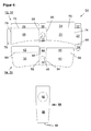
- FIG. 4 shows a schematic representation of a blank 54 for the production of the carton 10 for storage and metered dispensing of goods.
- the blank 54 in this case comprises a first blanking element 56 for forming the outer box part 12, wherein the outer box part 12 the outer bottom wall 16 and via the bending lines 66, 68 connected to the outer bottom wall 16 outer side walls 18, 20 and a top wall 22, via a further, parallel to the bending lines 66, 68 extending bending line 74 is connected to the outer side wall 20.
- the first blanking element 56 comprises the rear wall 24, which is connected to the outer side wall 20 via a further bending line 70 extending perpendicular to the bending lines 66, 68.
- a second blanking element 58 is used to form the inner box part 14, wherein the inner box part 14, the inner bottom wall 36 and the inner bottom wall 36 via bending lines 82, 84 connected inner side walls 38, 40 and the rear wall 42, via a further, perpendicular to the bending lines 82, 84th extending bending line 88 is connected to the inner side wall 38.
- the blank 54 comprises a third blanking element 60 for forming the strip-like element 50.
- the first blanking element 56, the second blanking element 58 and the third blanking element 60 are made of the same material.
- the third blank element 60 is formed as a separate element. With the same choice of material, however, it is also possible to form the third blanking element 60 in one piece with the second blanking element 58.
- the carton described as well as the blank for producing the package described is usually made of cardboard, paper or plastic or a combination thereof. Other suitable materials are conceivable.
Landscapes
- Engineering & Computer Science (AREA)
- Mechanical Engineering (AREA)
- Cartons (AREA)
Priority Applications (1)
| Application Number | Priority Date | Filing Date | Title |
|---|---|---|---|
| EP10157390A EP2368806A1 (fr) | 2010-03-23 | 2010-03-23 | Boîte de pliage |
Applications Claiming Priority (1)
| Application Number | Priority Date | Filing Date | Title |
|---|---|---|---|
| EP10157390A EP2368806A1 (fr) | 2010-03-23 | 2010-03-23 | Boîte de pliage |
Publications (1)
| Publication Number | Publication Date |
|---|---|
| EP2368806A1 true EP2368806A1 (fr) | 2011-09-28 |
Family
ID=42342708
Family Applications (1)
| Application Number | Title | Priority Date | Filing Date |
|---|---|---|---|
| EP10157390A Ceased EP2368806A1 (fr) | 2010-03-23 | 2010-03-23 | Boîte de pliage |
Country Status (1)
| Country | Link |
|---|---|
| EP (1) | EP2368806A1 (fr) |
Cited By (2)
| Publication number | Priority date | Publication date | Assignee | Title |
|---|---|---|---|---|
| EP2631189A1 (fr) | 2012-02-24 | 2013-08-28 | Carl Edelmann GmbH | Boîte de pliage |
| WO2019116194A1 (fr) * | 2017-12-12 | 2019-06-20 | G.D S.P.A. | Emballage distributeur à ouverture coulissante pour articles en vrac |
Citations (4)
| Publication number | Priority date | Publication date | Assignee | Title |
|---|---|---|---|---|
| FR1208736A (fr) * | 1958-11-19 | 1960-02-25 | Emballage | |
| CH473012A (de) | 1968-12-23 | 1969-05-31 | Merz & Co Ag | Schachtel |
| GB1394740A (en) * | 1971-06-07 | 1975-05-21 | Gero G Gero A Distefano | Cigarette dispensing package |
| WO2010022888A2 (fr) * | 2008-08-26 | 2010-03-04 | Philip Morris Products S.A. | Récipient à élément élastique |
-
2010
- 2010-03-23 EP EP10157390A patent/EP2368806A1/fr not_active Ceased
Patent Citations (4)
| Publication number | Priority date | Publication date | Assignee | Title |
|---|---|---|---|---|
| FR1208736A (fr) * | 1958-11-19 | 1960-02-25 | Emballage | |
| CH473012A (de) | 1968-12-23 | 1969-05-31 | Merz & Co Ag | Schachtel |
| GB1394740A (en) * | 1971-06-07 | 1975-05-21 | Gero G Gero A Distefano | Cigarette dispensing package |
| WO2010022888A2 (fr) * | 2008-08-26 | 2010-03-04 | Philip Morris Products S.A. | Récipient à élément élastique |
Cited By (3)
| Publication number | Priority date | Publication date | Assignee | Title |
|---|---|---|---|---|
| EP2631189A1 (fr) | 2012-02-24 | 2013-08-28 | Carl Edelmann GmbH | Boîte de pliage |
| WO2019116194A1 (fr) * | 2017-12-12 | 2019-06-20 | G.D S.P.A. | Emballage distributeur à ouverture coulissante pour articles en vrac |
| US11634249B2 (en) | 2017-12-12 | 2023-04-25 | G.D S.P.A. | Slide-open dispenser package for loose articles |
Similar Documents
| Publication | Publication Date | Title |
|---|---|---|
| DE60219214T2 (de) | Kindersichere verpackung mit verschiebbarem einsatzabschnitt | |
| DE102014013821A1 (de) | Klappschachtel für Zigaretten | |
| EP2465787B1 (fr) | Emballage pour deux raclettes d'essuie-glace à barre plate | |
| EP3173360A1 (fr) | Emballage et section destinés a la fabrication d'un emballage | |
| EP2368806A1 (fr) | Boîte de pliage | |
| DE202010006381U1 (de) | Faltschachtelzuschnitt und daraus gefaltete Faltschachtel | |
| DE202022102821U1 (de) | Verpackungseinlage, Aufnahmebehälter und Verpackung | |
| EP3770081A1 (fr) | Doublure interne pour un emballage et emballage | |
| DE202010006107U1 (de) | Faltschachtel | |
| AT413813B (de) | Behälter mit deckel, mit drehverschluss, aus flachem material | |
| EP1515627A1 (fr) | Boite destinee a contenir au moins un crayon | |
| DE202015101298U1 (de) | Schachtel aus Karton | |
| DE202010002096U1 (de) | Verpackung und Zuschnitt zur Herstellung einer Verpackung | |
| DE102012018759A1 (de) | Verpackung und Zuschnitt dafür | |
| DE202022106180U1 (de) | Behälter und Zuschnitt zur Herstellung eines Behälters | |
| WO2019015984A1 (fr) | Contenant | |
| EP3118138B1 (fr) | Emballage et section destinee a la fabrication d'un emballage | |
| DE102008030684A1 (de) | Faltschachtel | |
| DE202022106312U1 (de) | Behälter, Zuschnitt und Verpackung | |
| DE202009008875U1 (de) | Zuschnitt für einen Behälterträger | |
| DE202011051159U1 (de) | Zuschnitt für Kartonschachtel mit Deckel | |
| EP4365098A1 (fr) | Récipient et flan pour la fabrication d'un récipient | |
| WO2024094782A1 (fr) | Contenant et ébauche de production d'un contenant | |
| EP4180347A1 (fr) | Récipient et découpe destinée à la fabrication d'un récipient | |
| DE19544116A1 (de) | Röhrenförmiger Verpackungsbehälter |
Legal Events
| Date | Code | Title | Description |
|---|---|---|---|
| PUAI | Public reference made under article 153(3) epc to a published international application that has entered the european phase |
Free format text: ORIGINAL CODE: 0009012 |
|
| AK | Designated contracting states |
Kind code of ref document: A1 Designated state(s): AT BE BG CH CY CZ DE DK EE ES FI FR GB GR HR HU IE IS IT LI LT LU LV MC MK MT NL NO PL PT RO SE SI SK SM TR |
|
| AX | Request for extension of the european patent |
Extension state: AL BA ME RS |
|
| STAA | Information on the status of an ep patent application or granted ep patent |
Free format text: STATUS: THE APPLICATION HAS BEEN REFUSED |
|
| 18R | Application refused |
Effective date: 20111119 |