EP2368806A1 - Folding box - Google Patents
Folding box Download PDFInfo
- Publication number
- EP2368806A1 EP2368806A1 EP10157390A EP10157390A EP2368806A1 EP 2368806 A1 EP2368806 A1 EP 2368806A1 EP 10157390 A EP10157390 A EP 10157390A EP 10157390 A EP10157390 A EP 10157390A EP 2368806 A1 EP2368806 A1 EP 2368806A1
- Authority
- EP
- European Patent Office
- Prior art keywords
- box part
- wall
- bottom wall
- outer box
- side walls
- Prior art date
- Legal status (The legal status is an assumption and is not a legal conclusion. Google has not performed a legal analysis and makes no representation as to the accuracy of the status listed.)
- Ceased
Links
Images


Classifications
-
- B—PERFORMING OPERATIONS; TRANSPORTING
- B65—CONVEYING; PACKING; STORING; HANDLING THIN OR FILAMENTARY MATERIAL
- B65D—CONTAINERS FOR STORAGE OR TRANSPORT OF ARTICLES OR MATERIALS, e.g. BAGS, BARRELS, BOTTLES, BOXES, CANS, CARTONS, CRATES, DRUMS, JARS, TANKS, HOPPERS, FORWARDING CONTAINERS; ACCESSORIES, CLOSURES, OR FITTINGS THEREFOR; PACKAGING ELEMENTS; PACKAGES
- B65D5/00—Rigid or semi-rigid containers of polygonal cross-section, e.g. boxes, cartons or trays, formed by folding or erecting one or more blanks made of paper
- B65D5/42—Details of containers or of foldable or erectable container blanks
- B65D5/72—Contents-dispensing means
- B65D5/728—Contents-dispensing means for drawer-and-shell-type containers
-
- B—PERFORMING OPERATIONS; TRANSPORTING
- B65—CONVEYING; PACKING; STORING; HANDLING THIN OR FILAMENTARY MATERIAL
- B65D—CONTAINERS FOR STORAGE OR TRANSPORT OF ARTICLES OR MATERIALS, e.g. BAGS, BARRELS, BOTTLES, BOXES, CANS, CARTONS, CRATES, DRUMS, JARS, TANKS, HOPPERS, FORWARDING CONTAINERS; ACCESSORIES, CLOSURES, OR FITTINGS THEREFOR; PACKAGING ELEMENTS; PACKAGES
- B65D11/00—Containers having bodies formed by interconnecting or uniting two or more rigid, or substantially rigid, components made wholly or mainly of plastics material
- B65D11/10—Containers having bodies formed by interconnecting or uniting two or more rigid, or substantially rigid, components made wholly or mainly of plastics material of polygonal cross-section and all parts being permanently connected to each other
- B65D11/12—Containers having bodies formed by interconnecting or uniting two or more rigid, or substantially rigid, components made wholly or mainly of plastics material of polygonal cross-section and all parts being permanently connected to each other of drawer-and-shell type
-
- B—PERFORMING OPERATIONS; TRANSPORTING
- B65—CONVEYING; PACKING; STORING; HANDLING THIN OR FILAMENTARY MATERIAL
- B65D—CONTAINERS FOR STORAGE OR TRANSPORT OF ARTICLES OR MATERIALS, e.g. BAGS, BARRELS, BOTTLES, BOXES, CANS, CARTONS, CRATES, DRUMS, JARS, TANKS, HOPPERS, FORWARDING CONTAINERS; ACCESSORIES, CLOSURES, OR FITTINGS THEREFOR; PACKAGING ELEMENTS; PACKAGES
- B65D5/00—Rigid or semi-rigid containers of polygonal cross-section, e.g. boxes, cartons or trays, formed by folding or erecting one or more blanks made of paper
- B65D5/38—Drawer-and-shell type containers
Definitions
- the present invention relates to a folding box for storage and metered dispensing of goods comprising an outer box part and an inner box part, wherein the outer box part and the inner box part are arranged displaceable to each other, such that when moving the inner box part relative to the outer box part at least one opening in an inner bottom wall of the inner box part with at least one opening in an outer bottom wall of the outer box part at least partially to form a discharge opening for the metered delivery of goods comes to cover and the displacement of the inner box part takes place relative to the outer box part against a spring force.
- the invention further relates to a blank for producing a carton for storage and metered dispensing of goods.
- Such a carton is from the CH 473 012 known.
- a mecanicschachtelteil is slidably disposed in an outer box part, wherein the inner box part is urged by spring action into an end position, from which it is displaceable against the spring action in a position in which a removal opening of the inner box part coincides with a corresponding opening of the outer box part.
- a disadvantage of this known carton is that it consists of two completely formed box parts. This means that only a storage space of the inner box part is provided for receiving goods.
- the arrangement of a spring element in a separate space within the outer box part of the Folding box overall formed large volume. However, only a part of this volume, namely the mentioned receiving area of the inner box part for receiving goods is available.
- the known construction is structurally complex.
- a folding box according to the invention for storage and metered dispensing of goods comprises an outer box part and an inner box part, wherein the outer box part and the inner box part are arranged displaceable relative to each other, such that when moving the inner box part relative to the outer box part at least one opening in an inner bottom wall of the inner box part with at least one Opening in an outer bottom wall of the outer box part at least partially to form a discharge opening for the metered delivery of goods comes to cover.
- the displacement of the inner box part takes place relative to the outer box part against a spring force.
- the outer box part and the inner box part form a common receiving space for the goods to be stored and are hinged together in a common corner area.
- the folding box Due to the formation of a common receiving space through the outer box part and the inner box part according to the invention an enlarged receiving volume for Goods provided. Due to the articulated connection of the two box parts in a common corner region, the folding box is easy to operate, especially with one hand. In addition, the carton according to the invention can be easily manufactured, since this only a folding simple basic blanks is necessary.
- the outer box part and the inner box part are connected by means of a hinged to a top wall of the outer box part connecting plate which is attached to a rear wall of the inner box part.
- the outer box part comprises the outer bottom wall and the outer wall opposite lid wall and outer wall connected via bending lines outer side walls and a rear wall which is arranged between the outer side walls.
- the inner box part includes the inner bottom wall and inner side walls connected to the inner bottom wall via bending lines and also a rear wall. This configuration of the outer box part and the inner box part results in a common receiving volume for goods within the carton.
- the inner side walls are formed such that they rest against a maximum displacement of the inner box part relative to the outer box part on the inner sides of the top wall or a bonded to the top wall adhesive flap and the rear wall of the outer box part or an adhesive flap connected to the rear wall and before Reaching this state and in the non-moving state of the carton do not rest against the inner sides of the top wall or said adhesive flap and the rear wall of the outer box part or said adhesive tabs and thus at least partially spaced therefrom.
- a defined displacement of the inner box part relative to the outer box part becomes possible.
- a displacement path of the inner box part is defined within the outer box part.
- the inner side walls may be rounded in the area between the top wall and the rear wall of the outer box part. It is also possible that the inner side walls are formed longer in the region of the cover wall of the outer box part than in the area connected to the bottom wall of the inner box part. Furthermore, there is the possibility that the outer side walls are formed longer in the area connected to the top wall of the outer box part than in the area connected to the bottom wall of the outer box part. Finally, at least one outer side wall may have at least one bulge on the sides opposite the rear wall. Due to the large number of design options, it is possible according to the invention to create individual packaging units which take particular account of the shape and nature of the goods to be stored.
- At least one flexible, strip-like element is connected to the inside of the bottom wall of the inner box part to achieve the spring force or a spring action, such that at least when moving the inner box part relative to the outer box part one end of the strip-like element on an inner side the rear wall of the outer box part or an inner side of an adhesive flap connected to the rear wall abuts and is bent to produce a displacement of the opposing spring force.
- the strip-like element may be formed as a separate element or integrally with the inside of the bottom wall of the inner box part.
- the strip-like element made of paper, cardboard, a rubber-like material or plastic.
- the inner box part and the strip-like element are made of the same material, the inner box part with the strip-like element can be produced in one piece from a blank.
- the outer box part and / or the inner box part consist of paper, cardboard, plastic or a combination of these materials. This makes it according to the invention possible to use suitable materials for specific applications.
- An inventive blank for producing a folding box for storage and metered dispensing of goods comprises a first blank element for forming a theoryschachtelteils, wherein the infrastructureschachtelteil an outer bottom wall and bending lines with the outer bottom wall connected outer side walls and a top wall, via a further, parallel to said bending lines extending bending line is connected to the outer side wall and a rear wall, which is connected via a further, perpendicular to said bending lines extending bending line with the outer side wall.
- the blank comprises a second blanking element for forming an inner box part, the inner box part having an inner bottom wall and inner side walls connected to the inner bottom wall via bending lines and a rear wall connected to the inner side wall via a further bending line extending perpendicular to the said bending lines.
- the blank comprises a third blank element for forming at least one strip-like element.
- the third blanking element may be formed as a separate element or integrally with the second blanking element.
- Such blanks according to the invention can be produced easily and, in the folded state, provide a folding box which has an increased receiving volume for goods.
- the blank elements can consist of paper, cardboard, plastic or a combination of these materials.
- the FIG. 1 shows a schematic representation of a carton 10 for storage and metered dispensing of goods.
- the folding box 10 comprises an outer box part 12 and an inner box part 14, wherein the outer box part 12 and the inner box part 14 are arranged displaceable to each other, such that when moving the inner box part 14 relative to the outer box part 12 an opening 48 (see also Figures 2 and 3 ) comes in an inner bottom wall 36 of the inner box part 14 with an opening 26 in an outer bottom wall 16 of the outer box part 12 at least partially to form a discharge opening for the metered delivery of the goods to cover.
- the outer box part 12 and the inner box part 14 form a common receiving space 62 (see also FIG. 3 ) for the goods to be stored.
- outer box part 12 and the inner box part 14 are hinged together in a common corner area 64.
- the outer box part 12 and the inner box part 14 by means of a hinged to a top wall 22 of the outer box part 12 connecting plate 34 which is fixed to a rear wall 42 of the inner box part 14, respectively. This results in an articulated connection between the outer box part 12 and the inner box part 14 in the common corner area 64.
- both the outer box part 12 and the inner box part 14 are made of cardboard.
- FIG. 2 shows a schematic representation of the individual elements of the carton 10 according to FIG. 1
- the outer box part 12 and the inner box part 14 are designed such that the inner side walls 38, 40 can engage in the interior space formed by the outer box part 12.
- the inner side walls 38, 40 bear against the inner sides of the outer side walls 18, 20.
- the inner side walls 38, 40 in the region between the cover wall 22 and the rear wall 24 of the outer box part 12 - in the assembled state of the folding box 10 - is rounded.
- the inner side walls 38, 40 are formed longer in the region of the cover wall 22 of the outer box part 12-again based on the assembled state of the folded box 10 -than in the area connected to the bottom wall 36 of the inner box part 14.
- the outer side walls 18, 20 are formed longer in the area connected to the top wall 22 of the outer box part 12 than in the region connected to the bottom wall 16 of the outer box part 12. It can be seen that the outer side walls 18, 20 at the opposite sides of the rear wall 24 have a same shape formed bulge. The bulges facilitate moving or pressing the inner box part 14 in the outer box part 12 (see also FIG. 1 ).
- FIG. 3 shows a schematic sectional view of the carton 10 according to FIG. 1 ,
- the outer side wall 20 of the outer box part 12 has been removed.
- the carton 10 is - as well as in FIG. 1 - shown in an uncompressed state.
- the inner side walls 38, 40 are formed such that they at a maximum displacement of the inner box part 14 relative to the outer box part 12 on the inner sides of the cover wall 22 and one with the Cover wall 22 connected adhesive tab 78 abut.
- the inner side walls 38, 40 are also located on the rear wall 24 of the Outer box part 12 or connected to the rear wall adhesive tab 28, 30, 32 at.
- the inner side walls 38, 40 are not on the inner sides of the top wall 22 or the adhesive flap 78 and the rear wall 24 or the adhesive tabs 28, 30, 32 of the outer box part 12 and are spaced therefrom.
- a flexible, strip-like element 50 is connected to the inside of the bottom wall 36 of the inner box part 14, such that at least when moving the inner box part 14 relative to the outer box part 12 has an end 92 of the strip-like Element 50 on an inner side of the rear wall 24 of the outer box part 12 or an inner side of an adhesive plate connected to the rear wall 24, 32 abuts and is bent to produce a displacement of the opposing spring force.
- the strip-like element 50 already in the non-compressed state of the carton 10 on a bias.
- the end 92 of the element 50 acts against the adhesive flap 32.
- a common receiving space 62 is formed by the configuration of the folding box 10 or of the outer box part 12 and of the inner box part 14.
- the strip-like element 50 is made of plastic. But it is also possible to form the strip-like element 50 made of paper, cardboard or a rubber-like material. Furthermore, it is clear that in the illustrated embodiment, the strip-like element 50 is formed as a separate element. But it is also possible, the element 50 integral with the Form inside the bottom wall 36 of the inner box part 14.
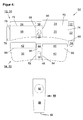
- FIG. 4 shows a schematic representation of a blank 54 for the production of the carton 10 for storage and metered dispensing of goods.
- the blank 54 in this case comprises a first blanking element 56 for forming the outer box part 12, wherein the outer box part 12 the outer bottom wall 16 and via the bending lines 66, 68 connected to the outer bottom wall 16 outer side walls 18, 20 and a top wall 22, via a further, parallel to the bending lines 66, 68 extending bending line 74 is connected to the outer side wall 20.
- the first blanking element 56 comprises the rear wall 24, which is connected to the outer side wall 20 via a further bending line 70 extending perpendicular to the bending lines 66, 68.
- a second blanking element 58 is used to form the inner box part 14, wherein the inner box part 14, the inner bottom wall 36 and the inner bottom wall 36 via bending lines 82, 84 connected inner side walls 38, 40 and the rear wall 42, via a further, perpendicular to the bending lines 82, 84th extending bending line 88 is connected to the inner side wall 38.
- the blank 54 comprises a third blanking element 60 for forming the strip-like element 50.
- the first blanking element 56, the second blanking element 58 and the third blanking element 60 are made of the same material.
- the third blank element 60 is formed as a separate element. With the same choice of material, however, it is also possible to form the third blanking element 60 in one piece with the second blanking element 58.
- the carton described as well as the blank for producing the package described is usually made of cardboard, paper or plastic or a combination thereof. Other suitable materials are conceivable.
Abstract
Description
Die vorliegende Erfindung betrifft eine Faltschachtel zur Aufbewahrung und dosierten Abgabe von Waren umfassend ein Außenschachtelteil und ein Innenschachtelteil, wobei das Außenschachtelteil und das Innenschachtelteil verschiebbar zueinander angeordnet sind, derart, dass bei einem Verschieben des Innenschachtelteils relativ zum Außenschachtelteil mindestens eine Öffnung in einer Innenbodenwand des Innenschachtelteils mit mindestens einer Öffnung in einer Außenbodenwand des Außenschachtelteils zumindest teilweise unter Bildung einer Abgabeöffnung für die dosierte Abgabe von Waren zur Deckung kommt und das Verschieben des Innenschachtelteils relativ zum Außenschachtelteil entgegen einer Federkraft erfolgt. Die Erfindung betrifft weiterhin einen Zuschnitt zur Herstellung einer Faltschachtel zur Aufbewahrung und dosierten Abgabe von Waren.The present invention relates to a folding box for storage and metered dispensing of goods comprising an outer box part and an inner box part, wherein the outer box part and the inner box part are arranged displaceable to each other, such that when moving the inner box part relative to the outer box part at least one opening in an inner bottom wall of the inner box part with at least one opening in an outer bottom wall of the outer box part at least partially to form a discharge opening for the metered delivery of goods comes to cover and the displacement of the inner box part takes place relative to the outer box part against a spring force. The invention further relates to a blank for producing a carton for storage and metered dispensing of goods.
Eine derartige Faltschachtel ist aus der
Es ist daher Aufgabe der vorliegenden Erfindung, eine Faltschachtel der eingangs genannten Art bereitzustellen, welche einfach herzustellen und leicht betätigbar ist sowie ein vergrößertes Aufnahmevolumen für Waren bereitstellt.It is therefore an object of the present invention to provide a carton of the type mentioned, which is easy to manufacture and easy to operate and provides an increased receiving volume for goods.
Es ist weiterhin Aufgabe der vorliegenden Erfindung, einen gattungsgemäßen Zuschnitt zur Herstellung einer Faltschachtel bereitzustellen, welcher einfach herzustellen ist und ein vergrößertes Aufnahmevolumen für Waren der fertigen Faltschachtel bereitstellt.It is a further object of the present invention to provide a generic blank for producing a carton, which is easy to manufacture and provides an increased receiving volume for goods of the finished carton.
Zur Lösung dieser Aufgaben dienen eine Faltschachtel mit den Merkmalen des Anspruchs 1 sowie ein Zuschnitt mit den Merkmalen des Anspruchs 9.To solve these problems serve a carton with the features of claim 1 and a blank with the features of claim 9.
Vorteilhafte Ausgestaltungen der erfindungsgemäßen Faltschachtel und des erfindungsgemäßen Zuschnitts sind in den jeweiligen Unteransprüchen beschrieben.Advantageous embodiments of the carton according to the invention and of the blank according to the invention are described in the respective subclaims.
Eine erfindungsgemäße Faltschachtel zur Aufbewahrung und dosierten Abgabe von Waren umfasst ein Außenschachtelteil und ein Innenschachtelteil, wobei das Außenschachtelteil und das Innenschachtelteil verschiebbar zueinander angeordnet sind, derart, dass bei einem Verschieben des Innenschachtelteils relativ zum Außenschachtelteil mindestens eine Öffnung in einer Innenbodenwand des Innenschachtelteils mit mindestens einer Öffnung in einer Außenbodenwand des Außenschachtelteils zumindest teilweise unter Bildung einer Abgabeöffnung für die dosierte Abgabe von Waren zur Deckung kommt. Das Verschieben des Innenschachtelteils erfolgt dabei relativ zum Außenschachtelteil entgegen einer Federkraft. Des Weiteren bilden das Außenschachtelteil und das Innenschachtelteil einen gemeinsamen Aufnahmeraum für die aufzubewahrenden Waren und sind in einem gemeinsamen Eckbereich gelenkig miteinander verbunden. Durch die Ausbildung eines gemeinsamen Aufnahmeraums durch das Außenschachtelteil und das Innenschachtelteil wird erfindungsgemäß ein vergrößertes Aufnahmevolumen für Waren bereitgestellt. Durch die gelenkige Verbindung der beiden Schachtelteile in einem gemeinsamen Eckbereich ist die Faltschachtel leicht, insbesondere auch einhändig zu bedienen. Zudem kann die erfindungsgemäße Faltschachtel einfach hergestellt werden, da hierfür nur ein Zusammenfalten einfacher Grundzuschnitte notwendig ist.A folding box according to the invention for storage and metered dispensing of goods comprises an outer box part and an inner box part, wherein the outer box part and the inner box part are arranged displaceable relative to each other, such that when moving the inner box part relative to the outer box part at least one opening in an inner bottom wall of the inner box part with at least one Opening in an outer bottom wall of the outer box part at least partially to form a discharge opening for the metered delivery of goods comes to cover. The displacement of the inner box part takes place relative to the outer box part against a spring force. Furthermore, the outer box part and the inner box part form a common receiving space for the goods to be stored and are hinged together in a common corner area. Due to the formation of a common receiving space through the outer box part and the inner box part according to the invention an enlarged receiving volume for Goods provided. Due to the articulated connection of the two box parts in a common corner region, the folding box is easy to operate, especially with one hand. In addition, the carton according to the invention can be easily manufactured, since this only a folding simple basic blanks is necessary.
In einer vorteilhaften Ausgestaltung der erfindungsgemäßen Faltschachtel sind das Außenschachtelteil und das Innenschachtelteil mittels einer an einer Deckelwand des Außenschachtelteils angelenkten Verbindungslasche, die an einer Rückwand des Innenschachtelteils befestigt ist, verbunden. Dadurch ergibt sich eine einfach herzustellende, sichere Gelenkverbindung zwischen dem Außenschachtelteil und dem Innenschachtelteil. Es ist aber auch möglich, dass das Außenschachtelteil und das Innenschachtelteil mittels einer Drehgelenkverbindung miteinander verbunden sind.In an advantageous embodiment of the folding box according to the invention, the outer box part and the inner box part are connected by means of a hinged to a top wall of the outer box part connecting plate which is attached to a rear wall of the inner box part. This results in a simple to produce, secure joint connection between the outer box part and the inner box part. But it is also possible that the outer box part and the inner box part are connected to each other by means of a hinge connection.
In weiteren vorteilhaften Ausgestaltungen der erfindungsgemäßen Faltschachtel umfasst das Außenschachtelteil die Außenbodenwand und die der Außenbodenwand gegenüberliegende Deckelwand sowie mit der Außenbodenwand über Biegelinien verbundene Außenseitenwände und eine Rückwand, die zwischen den Außenseitenwänden angeordnet ist. Das Innenschachtelteil umfasst dabei die Innenbodenwand sowie mit der Innenbodenwand über Biegelinien verbundene Innenseitenwände und ebenfalls eine Rückwand. Durch diese Ausgestaltung des Außenschachtelteils und des Innenschachtelteils ergibt sich ein gemeinsames Aufnahmevolumen für Waren innerhalb der Faltschachtel. Dabei ist es möglich, dass die Innenseitenwände derart ausgebildet sind, dass sie bei einer maximalen Verschiebung des Innenschachtelteils relativ zum Außenschachtelteil an den Innenseiten der Deckelwand oder einer mit der Deckelwand verbundenen Klebelasche sowie der Rückwand des Außenschachtelteils oder einer mit der Rückwand verbundenen Klebelasche anliegen und vor Erreichen dieses Zustands sowie im nicht-bewegten Zustand der Faltschachtel nicht an den Innenseiten der Deckelwand oder der genannten Klebelasche und der Rückwand des Außenschachtelteils oder den genannten Klebelaschen anliegen und somit zumindest teilweise davon beabstandet sind. Dadurch wird ein definiertes Verschieben des Innenschachtelteils relativ zum Außenschachtelteil möglich. Je nach Ausgestaltung der Innenseitenwände wird ein Verschiebeweg des Innenschachtelteils innerhalb des Außenschachtelteils definiert.In further advantageous embodiments of the folding box according to the invention, the outer box part comprises the outer bottom wall and the outer wall opposite lid wall and outer wall connected via bending lines outer side walls and a rear wall which is arranged between the outer side walls. The inner box part includes the inner bottom wall and inner side walls connected to the inner bottom wall via bending lines and also a rear wall. This configuration of the outer box part and the inner box part results in a common receiving volume for goods within the carton. It is possible that the inner side walls are formed such that they rest against a maximum displacement of the inner box part relative to the outer box part on the inner sides of the top wall or a bonded to the top wall adhesive flap and the rear wall of the outer box part or an adhesive flap connected to the rear wall and before Reaching this state and in the non-moving state of the carton do not rest against the inner sides of the top wall or said adhesive flap and the rear wall of the outer box part or said adhesive tabs and thus at least partially spaced therefrom. As a result, a defined displacement of the inner box part relative to the outer box part becomes possible. Depending on the configuration of the inner side walls, a displacement path of the inner box part is defined within the outer box part.
So können beispielsweise die Innenseitenwände im Bereich zwischen der Deckelwand und der Rückwand des Außenschachtelteils abgerundet ausgebildet sein. Es ist auch möglich, dass die Innenseitenwände im Bereich der Deckelwand des Außenschachtelteils länger ausgebildet sind als in dem mit der Bodenwand des Innenschachtelteils verbundenen Bereich. Des Weiteren besteht die Möglichkeit, dass die Außenseitenwände in dem mit der Deckelwand des Außenschachtelteils verbundenen Bereich länger ausgebildet sind als in dem mit der Bodenwand des Außenschachtelteils verbundenen Bereich. Schließlich kann mindestens eine Außenseitenwand an den der Rückwand gegenüberliegenden Seiten mindestens eine Ausbuchtung aufweisen. Durch die Vielzahl der Ausgestaltungsmöglichkeiten ist es erfindungsgemäß möglich, individuelle Verpackungseinheiten zu schaffen, die insbesondere auf die Form und Natur der aufzubewahrenden Waren Rücksicht nimmt.For example, the inner side walls may be rounded in the area between the top wall and the rear wall of the outer box part. It is also possible that the inner side walls are formed longer in the region of the cover wall of the outer box part than in the area connected to the bottom wall of the inner box part. Furthermore, there is the possibility that the outer side walls are formed longer in the area connected to the top wall of the outer box part than in the area connected to the bottom wall of the outer box part. Finally, at least one outer side wall may have at least one bulge on the sides opposite the rear wall. Due to the large number of design options, it is possible according to the invention to create individual packaging units which take particular account of the shape and nature of the goods to be stored.
In weiteren vorteilhaften Ausgestaltungen der erfindungsgemäßen Faltschachtel ist zur Erzielung der Federkraft beziehungsweise einer Federwirkung mindestens ein biegsames, streifenartiges Element mit der Innenseite der Bodenwand des Innenschachtelteils verbunden, derart, dass zumindest bei einem Verschieben des Innenschachtelteils relativ zum Außenschachtelteil ein Ende des streifenartigen Elements an einer Innenseite der Rückwand des Außenschachtelteils oder einer Innenseite einer mit der Rückwand verbundenen Klebelasche anliegt und unter Erzeugung einer der Verschiebung entgegengerichteten Federkraft gebogen wird. Durch eine derartige Ausgestaltung wird ein konstruktiv einfach herzustellendes Federelement zur Erzielung der Federkraft beziehungsweise einer Federwirkung bereitgestellt. Das streifenartige Element kann dabei als separates Element oder einstückig mit der Innenseite der Bodenwand des Innenschachtelteils ausgebildet sein. Insbesondere kann das streifenartige Element aus Papier, Karton, einem gummiartigen Material oder Kunststoff bestehen. Für den Fall, dass das Innenschachtelteil und streifenartige Element aus demselben Material bestehen, kann das Innenschachtelteil mit dem streifenartigen Element einstückig aus einem Zuschnitt hergestellt werden.In further advantageous embodiments of the folding box according to the invention at least one flexible, strip-like element is connected to the inside of the bottom wall of the inner box part to achieve the spring force or a spring action, such that at least when moving the inner box part relative to the outer box part one end of the strip-like element on an inner side the rear wall of the outer box part or an inner side of an adhesive flap connected to the rear wall abuts and is bent to produce a displacement of the opposing spring force. By such a configuration, a structurally simple to produce spring element for achieving the spring force or a spring action is provided. The strip-like element may be formed as a separate element or integrally with the inside of the bottom wall of the inner box part. In particular, the strip-like element made of paper, cardboard, a rubber-like material or plastic. In the event that the inner box part and the strip-like element are made of the same material, the inner box part with the strip-like element can be produced in one piece from a blank.
In weiteren vorteilhaften Ausgestaltungen der erfindungsgemäßen Faltschachtel bestehen das Außenschachtelteil und/oder das Innenschachtelteil aus Papier, Karton, Kunststoff oder einer Kombination dieser Materialien. Dadurch ist es erfindungsgemäß möglich, jeweils geeignete Materialien für spezifische Anwendungszwecke zu verwenden.In further advantageous embodiments of the folding box according to the invention, the outer box part and / or the inner box part consist of paper, cardboard, plastic or a combination of these materials. This makes it according to the invention possible to use suitable materials for specific applications.
Ein erfindungsgemäßer Zuschnitt zur Herstellung einer Faltschachtel zur Aufbewahrung und dosierten Abgabe von Waren umfasst ein erstes Zuschnittelement zur Ausbildung eines Außenschachtelteils, wobei das Außenschachtelteil eine Außenbodenwand und über Biegelinien mit der Außenbodenwand verbundene Außenseitenwände sowie eine Deckelwand, die über eine weitere, parallel zu den genannten Biegelinien verlaufende Biegelinie mit der Außenseitenwand verbunden ist und eine Rückwand, die über eine weitere, senkrecht zu den genannten Biegelinien verlaufene Biegelinie mit der Außenseitenwand verbunden ist. Des Weiteren umfasst der Zuschnitt ein zweites Zuschnittselement zur Ausbildung eines Innenschachtelteils, wobei das Innenschachtelteil eine Innenbodenwand sowie mit der Innenbodenwand über Biegelinien verbundene Innenseitenwände und eine Rückwand, die über eine weitere, senkrecht zu den genannten Biegelinien verlaufende Biegelinie mit der Innenseitenwand verbunden ist. Des Weiteren umfasst der Zuschnitt ein drittes Zuschnittelement zur Ausbildung von mindestens einem streifenartigen Element. Das dritte Zuschnittelement kann dabei als separates Element oder einstückig mit dem zweiten Zuschnittelement ausgebildet sein. Derartige erfindungsgemäße Zuschnitte können einfach hergestellt werden und stellen im zusammengefalteten Zustand eine Faltschachtel bereit, die ein vergrößertes Aufnahmevolumen für Waren aufweist. Die Zuschnittselemente können dabei aus Papier, Karton, Kunststoff oder einer Kombination dieser Materialien bestehen.An inventive blank for producing a folding box for storage and metered dispensing of goods comprises a first blank element for forming a Außenschachtelteils, wherein the Außenschachtelteil an outer bottom wall and bending lines with the outer bottom wall connected outer side walls and a top wall, via a further, parallel to said bending lines extending bending line is connected to the outer side wall and a rear wall, which is connected via a further, perpendicular to said bending lines extending bending line with the outer side wall. Furthermore, the blank comprises a second blanking element for forming an inner box part, the inner box part having an inner bottom wall and inner side walls connected to the inner bottom wall via bending lines and a rear wall connected to the inner side wall via a further bending line extending perpendicular to the said bending lines. Furthermore, the blank comprises a third blank element for forming at least one strip-like element. The third blanking element may be formed as a separate element or integrally with the second blanking element. Such blanks according to the invention can be produced easily and, in the folded state, provide a folding box which has an increased receiving volume for goods. The blank elements can consist of paper, cardboard, plastic or a combination of these materials.
Weitere Einzelheiten, Merkmale und Vorteile der Erfindung ergeben sich aus der folgenden Beschreibung des in den Figuren dargestellten Ausführungsbeispiels. Es zeigen
- Figur 1
- eine schematisch dargestellte seitliche Ansicht von unten auf eine erfindungsgemäßen Faltschachtel;
- Figur 2
- eine schematische Darstellung der Einzelelemente der erfindungsgemäßen Faltschachtel gemäß
Figur 1 ; - Figur 3
- eine schematische Schnittdarstellung der erfindungsgemäßen Faltschachtel gemäß
Figur 1 ; und - Figur 4
- eine schematische Darstellung eines erfindungsgemäßen Zuschnitts.
- FIG. 1
- a schematically illustrated side view from below of a carton according to the invention;
- FIG. 2
- a schematic representation of the individual elements of the carton according to the invention according to
FIG. 1 ; - FIG. 3
- a schematic sectional view of the carton according to the invention
FIG. 1 ; and - FIG. 4
- a schematic representation of a blank according to the invention.
Die
Des Weiteren erkennt man, dass das Außenschachtelteil 12 die Außenbodenwand 16 und die der Außenbodenwand 16 gegenüberliegende Deckelwand 22 sowie mit der Außenbodenwand 16 über Biegelinien 66, 68 verbundene Außenseitenwände 18, 20 (vergleiche auch
Des Weiteren erkennt man, dass zur Erzielung der Federkraft beziehungsweise einer Federwirkung ein biegsames, streifenartiges Element 50 mit der Innenseite der Bodenwand 36 des Innenschachtelteils 14 verbunden ist, derart, dass zumindest bei einem Verschieben des Innenschachtelteils 14 relativ zum Außenschachtelteil 12 eine Ende 92 des streifenartigen Elements 50 an einer Innenseite der Rückwand 24 des Außenschachtelteils 12 oder einer Innenseite einer mit der Rückwand 24 verbundenen Klebelasche 28, 32 anliegt und unter Erzeugung einer der Verschiebung entgegengerichteten Federkraft gebogen wird. In dem dargestellten Ausführungsbeispiel weist das streifenartige Element 50 bereits im nichtzusammengedrückten Zustand der Faltschachtel 10 eine Vorspannung auf. Zudem wirkt das Ende 92 des Elements 50 gegen die Klebelasche 32. Bei dem Zusammendrücken beziehungsweise einem Verschieben des Innenschachtelteils 14 gegenüber dem Außenschachtelteil 12 wird das Federelement weiter aufgebogen und erzeugt somit eine Gegenkraft gegen die Richtung des Verschiebens beziehungsweise Zusammendrückens. Durch das Verschieben des Innenschachtelteils 14 gegenüber dem Außenschachtelteil 12 kommt die Öffnung 48 der Innenbodenwand 36 mit der Öffnung 26 der Außenbodenwand 16 zur Deckung und erzeugt somit eine Abgabeöffnung für die dosierte Abgabe von Waren aus dem Aufnahmeraum 62 der Faltschachtel 10. Es wird deutlich, dass durch die Ausgestaltung der Faltschachtel 10 beziehungsweise des Außenschachtelteils 12 und des Innenschachtelteils 14 ein gemeinsamer Aufnahmeraum 62 gebildet wird.Furthermore, it can be seen that to achieve the spring force or a spring action, a flexible, strip-
In dem dargestellten Ausführungsbeispiel besteht das streifenartige Element 50 aus Kunststoff. Es ist aber auch möglich, das streifenartige Element 50 aus Papier, Karton oder einem gummiartigen Material auszubilden. Des Weiteren wird deutlich, dass in dem dargestellten Ausführungsbeispiel das streifenartige Element 50 als separates Element ausgebildet ist. Es ist aber auch möglich, das Element 50 einstückig mit der Innenseite der Bodenwand 36 des Innenschachtelteils 14 auszubilden.In the illustrated embodiment, the strip-
Ein zweites Zuschnittelement 58 dient zur Ausbildung des Innenschachtelteils 14, wobei das Innenschachtelteil 14 die Innenbodenwand 36 sowie mit der Innenbodenwand 36 über Biegelinien 82, 84 verbundene Innenseitenwände 38, 40 und die Rückwand 42, die über eine weitere, senkrecht zu den Biegelinien 82, 84 verlaufende Biegelinie 88 mit der Innenseitenwand 38 verbunden ist.A second blanking element 58 is used to form the
Des Weiteren umfasst der Zuschnitt 54 ein drittes Zuschnittelement 60 zur Ausbildung des streifenartigen Elements 50. In diesem Fall bestehen das erste Zuschnittelement 56, das zweite Zuschnittelement 58 und das dritte Zuschnittelement 60 aus dem gleichen Material. Bei der Verwendung von unterschiedlichen Materialien für die genannten Zuschnittelemente werden entsprechend separat ausgebildete Zuschnitte benötigt. Des Weiteren erkennt man, dass in dem dargestellten Ausführungsbeispiel das dritte Zuschnittelement 60 als separates Element ausgebildet ist. Bei gleicher Materialwahl ist es jedoch auch möglich, das dritte Zuschnittelement 60 einstückig mit dem zweiten Zuschnittelement 58 auszubilden.Furthermore, the blank 54 comprises a
Die beschriebene Faltschachtel wie auch der Zuschnitt zur Herstellung der beschriebenen Verpackung besteht üblicherweise aus Karton, Papier oder Kunststoff oder einer Kombination davon. Auch andere geeignete Materialien sind denkbar.The carton described as well as the blank for producing the package described is usually made of cardboard, paper or plastic or a combination thereof. Other suitable materials are conceivable.
Claims (15)
dadurch gekennzeichnet,
dass das Außenschachtelteil (12) und das Innenschachtelteil (14) einen gemeinsamen Aufnahmeraum (62) für die aufzubewahrenden Waren ausbilden und in einem gemeinsamen Eckbereich (64) gelenkig miteinander verbunden sind.Folding box for storage and metered dispensing of goods comprising an outer box part (12) and an inner box part (14), wherein the outer box part (12) and the inner box part (14) are arranged displaceable to each other, such that when moving the inner box part (14) relative to the outer box part (12) at least one opening (48) in an inner bottom wall (36) of the inner box part (14) with at least one opening (26) in an outer bottom wall (16) of the outer box part (12) at least partially forming a dispensing opening for the metered dispensing of goods comes to cover and the displacement of the inner box part (14) takes place relative to the outer box part (12) against a spring force,
characterized,
in that the outer box part (12) and the inner box part (14) form a common receiving space (62) for the goods to be stored and are hinged together in a common corner area (64).
dadurch gekennzeichnet,
dass das Außenschachtelteil (12) und das Innenschachtelteil (14) mittels einer an einer Deckelwand (22) des Außenschachtelteils (12) angelenkten Verbindungslasche (34), die an einer Rückwand (42) des Innenschachtelteils (14) befestigt ist, verbunden sind.Folding box according to claim 1,
characterized,
in that the outer box part (12) and the inner box part (14) are connected to a rear wall (42) of the inner box part by means of a connecting lug (34) articulated on a cover wall (22) of the outer box part (12) (14) is attached, are connected.
dadurch gekennzeichnet,
dass das Außenschachtelteil (12) und das Innenschachtelteil (14) mittels einer Drehgelenkverbindung miteinander verbunden sind.Folding box according to claim 1,
characterized,
in that the outer box part (12) and the inner box part (14) are connected to one another by means of a pivot connection.
dadurch gekennzeichnet,
dass das Außenschachtelteil (12) die Außenbodenwand (16) und die der Außenbodenwand (16) gegenüberliegende Deckelwand (22) sowie mit der Außenbodenwand (16) über Biegelinien (66, 68) verbundene Außenseitenwände (18, 20) und eine Rückwand (24), die zwischen den Außenseitenwänden (18, 20) angeordnet ist, umfasst und das Innenschachtelteil (14) die Innenbodenwand (36) sowie mit der Innenbodenwand (36) über Biegelinien (82, 84) verbundene Innenseitenwände (38, 40) und die Rückwand (42) umfasst.Folding box according to one of the preceding claims,
characterized,
in that the outer box part (12) comprises the outer bottom wall (16) and the lid wall (22) opposite the outer bottom wall (16) and outer side walls (18, 20) connected to the outer bottom wall (16) via bending lines (66, 68) and a rear wall (24). , which is arranged between the outer side walls (18, 20), and the inner box part (14) comprises the inner bottom wall (36) and inner side walls (38, 40) connected to the inner bottom wall (36) via bending lines (82, 84) and the rear wall (38). 42).
dadurch gekennzeichnet,
dass die Innenseitenwände (38, 40) derart ausgebildet sind, dass sie bei einer maximalen Verschiebung des Innenschachtelteils (14) relativ zum Außenschachtelteil (12) an den Innenseiten der Deckelwand (22) oder einer mit der Deckelwand (22) verbundenen Klebelasche (78) und der Rückwand (24) des Außenschachtelteils (12) oder einer mit der Rückwand (24) verbundenen Klebelasche (28, 30, 32) anliegen und vor Erreichen dieses Zustands sowie im nicht-bewegten Zustand der Faltschachtel (10) nicht an den Innenseiten der Deckelwand (22) oder der Klebelasche (78) und der Rückwand (24) des Außenschachtelteils (12) oder den Klebelaschen (28, 30, 32) anliegen und davon zumindest teilweise beabstandet sind.Folding box according to claim 4,
characterized,
in that the inner side walls (38, 40) are designed such that, with a maximum displacement of the inner box part (14) relative to the outer box part (12) on the inner sides of the cover wall (22) or an adhesive flap (78) connected to the cover wall (22). and the rear wall (24) of the outer box part (12) or one with the rear wall (24) connected adhesive tab (28, 30, 32) abut and before reaching this state and in the non-moving state of the carton (10) not on the insides of the Cover wall (22) or the adhesive flap (78) and the rear wall (24) of the outer box part (12) or the adhesive tabs (28, 30, 32) abut and are at least partially spaced therefrom.
dadurch gekennzeichnet,
dass die Innenseitenwände (38, 40) im Bereich zwischen der Deckelwand (22) und der Rückwand (24) des Außenschachtelteils (12) abgerundet ausgebildet sind.Folding box according to claim 5,
characterized,
in that the inner side walls (38, 40) in the region between the cover wall (22) and the rear wall (24) of the outer box part (12) are rounded.
dadurch gekennzeichnet,
dass die Innenseitenwände (38, 40) im Bereich der Deckelwand (22) des Außenschachtelteils (12) länger ausgebildet sind als in dem mit der Bodenwand (36) des Innenschachtelteils (14) verbundenen Bereich.Folding box according to claim 5 or 6,
characterized,
that the inner side walls (38, 40) in the region of the lid wall (22) of the outer pack part (12) are longer than the with the bottom wall (36) of the inner pack part (14) connected region.
dadurch gekennzeichnet,
dass die Außenseitenwände (18, 20) in dem mit der Deckelwand (22) des Außenschachtelteils (12) verbundenen Bereich länger ausgebildet sind als in dem mit der Bodenwand (16) des Außenschachtelteils (12) verbundenen Bereich.Folding box according to one of claims 4 to 7,
characterized,
in that the outer side walls (18, 20) are made longer in the region connected to the cover wall (22) of the outer box part (12) than in the region connected to the bottom wall (16) of the outer box part (12).
dadurch gekennzeichnet,
dass mindestens eine Außenseitenwand (18, 20) an den der Rückwand (24) gegenüberliegenden Seiten mindestens eine Ausbuchtung aufweist.Folding box according to one of claims 4 to 8,
characterized,
in that at least one outer side wall (18, 20) has at least one bulge on the sides opposite the rear wall (24).
dadurch gekennzeichnet,
dass zur Erzielung der Federkraft beziehungsweise einer Federwirkung mindestens ein biegsames, streifenartiges Element (50) mit der Innenseite der Bodenwand (36) des Innenschachtelteils (14) verbunden ist, derart, dass zumindest bei einem Verschieben des Innenschachtelteils (14) relativ zum Außenschachtelteil (12) ein Ende (92) des streifenartigen Elements (50) an einer Innenseite der Rückwand (24) des Außenschachtelteils (12) oder einer Innenseite einer mit der Rückwand (24) verbundenen Kleblasche (28, 32) anliegt und unter Erzeugung einer der Verschiebung entgegengerichteten Federkraft gebogen wird.Folding box according to one of the preceding claims,
characterized,
in that at least one flexible, strip-like element (50) is connected to the inside of the bottom wall (36) of the inner box part (14) in such a way that at least when the inner box part (14) is displaced relative to the outer box part (12) ) abuts an end (92) of the strip-like element (50) on an inner side of the rear wall (24) of the outer box part (12) or an inner side of an adhesive flap (28, 32) connected to the rear wall (24) and producing an opposite direction of displacement Spring force is bent.
dadurch gekennzeichnet,
dass das streifenartige Element (50) als separates Element oder einstückig mit der Innenseite der Bodenwand (36) des Innenschachtelteils (14) ausgebildet ist.Folding box according to claim 10,
characterized,
in that the strip-like element (50) is formed as a separate element or integrally with the inside of the bottom wall (36) of the inner box part (14).
dadurch gekennzeichnet,
dass das streifenartige Element (50) aus Papier, Karton, einem gummiartigen Material oder Kunststoff besteht.Folding box according to claim 10 or 11,
characterized,
in that the strip-like element (50) consists of paper, cardboard, a rubber-like material or plastic.
dadurch gekennzeichnet,
dass das Außenschachtelteil (12) und/oder das Innenschachtelteil (14) aus Papier, Karton, Kunststoff oder einer Kombination dieser Materialen bestehen.Folding box according to one of the preceding claims,
characterized,
that the outer pack part (12) and / or the inner box part (14) made of paper, cardboard, plastic or a combination of these materials exist.
dadurch gekennzeichnet,
dass das dritte Zuschnittelement (60) als separates Element oder einstückig mit dem zweiten Zuschnittelement (58) ausgebildet ist.Blank according to claim 14,
characterized,
in that the third blanking element (60) is formed as a separate element or integrally with the second blanking element (58).
Priority Applications (1)
| Application Number | Priority Date | Filing Date | Title |
|---|---|---|---|
| EP10157390A EP2368806A1 (en) | 2010-03-23 | 2010-03-23 | Folding box |
Applications Claiming Priority (1)
| Application Number | Priority Date | Filing Date | Title |
|---|---|---|---|
| EP10157390A EP2368806A1 (en) | 2010-03-23 | 2010-03-23 | Folding box |
Publications (1)
| Publication Number | Publication Date |
|---|---|
| EP2368806A1 true EP2368806A1 (en) | 2011-09-28 |
Family
ID=42342708
Family Applications (1)
| Application Number | Title | Priority Date | Filing Date |
|---|---|---|---|
| EP10157390A Ceased EP2368806A1 (en) | 2010-03-23 | 2010-03-23 | Folding box |
Country Status (1)
| Country | Link |
|---|---|
| EP (1) | EP2368806A1 (en) |
Cited By (2)
| Publication number | Priority date | Publication date | Assignee | Title |
|---|---|---|---|---|
| EP2631189A1 (en) | 2012-02-24 | 2013-08-28 | Carl Edelmann GmbH | Folding box |
| WO2019116194A1 (en) * | 2017-12-12 | 2019-06-20 | G.D S.P.A. | Slide-open dispenser package for loose articles |
Citations (4)
| Publication number | Priority date | Publication date | Assignee | Title |
|---|---|---|---|---|
| FR1208736A (en) * | 1958-11-19 | 1960-02-25 | Packaging | |
| CH473012A (en) | 1968-12-23 | 1969-05-31 | Merz & Co Ag | box |
| GB1394740A (en) * | 1971-06-07 | 1975-05-21 | Gero G Gero A Distefano | Cigarette dispensing package |
| WO2010022888A2 (en) * | 2008-08-26 | 2010-03-04 | Philip Morris Products S.A. | Container with resilient member |
-
2010
- 2010-03-23 EP EP10157390A patent/EP2368806A1/en not_active Ceased
Patent Citations (4)
| Publication number | Priority date | Publication date | Assignee | Title |
|---|---|---|---|---|
| FR1208736A (en) * | 1958-11-19 | 1960-02-25 | Packaging | |
| CH473012A (en) | 1968-12-23 | 1969-05-31 | Merz & Co Ag | box |
| GB1394740A (en) * | 1971-06-07 | 1975-05-21 | Gero G Gero A Distefano | Cigarette dispensing package |
| WO2010022888A2 (en) * | 2008-08-26 | 2010-03-04 | Philip Morris Products S.A. | Container with resilient member |
Cited By (3)
| Publication number | Priority date | Publication date | Assignee | Title |
|---|---|---|---|---|
| EP2631189A1 (en) | 2012-02-24 | 2013-08-28 | Carl Edelmann GmbH | Folding box |
| WO2019116194A1 (en) * | 2017-12-12 | 2019-06-20 | G.D S.P.A. | Slide-open dispenser package for loose articles |
| US11634249B2 (en) | 2017-12-12 | 2023-04-25 | G.D S.P.A. | Slide-open dispenser package for loose articles |
Similar Documents
| Publication | Publication Date | Title |
|---|---|---|
| DE60219214T2 (en) | CHILDREN-SAFE PACKAGING WITH MOVABLE INSERT SECTION | |
| DE102014013821A1 (en) | Folding box for cigarettes | |
| EP2465787B1 (en) | Packaging for two flat bar wiper blades | |
| EP3173360A1 (en) | Packaging and blank for producing packaging | |
| EP2368806A1 (en) | Folding box | |
| DE202010006381U1 (en) | Faltschachtelzuschnitt and folded out folding box | |
| DE202022102821U1 (en) | Packing liner, receptacle and packaging | |
| EP3770081A1 (en) | Package and inner collar for a package | |
| DE202010006107U1 (en) | folding | |
| AT413813B (en) | CONTAINER WITH LID, WITH TURNING, OF FLAT MATERIAL | |
| EP1515627A1 (en) | Receptacle for accommodating at least one pencil | |
| DE202015101298U1 (en) | Box made of cardboard | |
| DE102012018759A1 (en) | Package for use in retail sector for packaging of goods or articles for sale, has stack border section connected with wall sections across bending line, where stack border section is divided into two portions through another bending line | |
| DE202022106180U1 (en) | Container and blank for making a container | |
| WO2019015984A1 (en) | Container | |
| EP3118138B1 (en) | Packaging and blank for producing packaging | |
| DE102008030684A1 (en) | Folded box for storing and presenting stationery article, has base segments connected with walls arranged parallel to front- and rear walls and connected with walls that are arranged parallel to side walls by folding lines | |
| DE202022106312U1 (en) | Containers, cutting and packaging | |
| DE202009008875U1 (en) | Blank for a container carrier | |
| DE202011051159U1 (en) | Blank for cardboard box with lid | |
| EP4180347A1 (en) | Container and blank for producing a container | |
| DE19544116A1 (en) | Tubular packing container for various types of goods | |
| DE202022106181U1 (en) | Container and set to create a container | |
| AT517222B1 (en) | Containers, in particular for bottles | |
| DE202010002097U1 (en) | Packaging and cutting to produce a packaging |
Legal Events
| Date | Code | Title | Description |
|---|---|---|---|
| PUAI | Public reference made under article 153(3) epc to a published international application that has entered the european phase |
Free format text: ORIGINAL CODE: 0009012 |
|
| AK | Designated contracting states |
Kind code of ref document: A1 Designated state(s): AT BE BG CH CY CZ DE DK EE ES FI FR GB GR HR HU IE IS IT LI LT LU LV MC MK MT NL NO PL PT RO SE SI SK SM TR |
|
| AX | Request for extension of the european patent |
Extension state: AL BA ME RS |
|
| STAA | Information on the status of an ep patent application or granted ep patent |
Free format text: STATUS: THE APPLICATION HAS BEEN REFUSED |
|
| 18R | Application refused |
Effective date: 20111119 |