EP2367965B1 - Leitfähige beschichtungen auf ito-basis - Google Patents
Leitfähige beschichtungen auf ito-basis Download PDFInfo
- Publication number
- EP2367965B1 EP2367965B1 EP09818654.7A EP09818654A EP2367965B1 EP 2367965 B1 EP2367965 B1 EP 2367965B1 EP 09818654 A EP09818654 A EP 09818654A EP 2367965 B1 EP2367965 B1 EP 2367965B1
- Authority
- EP
- European Patent Office
- Prior art keywords
- ito
- process according
- content
- coating
- hydrolysable
- Prior art date
- Legal status (The legal status is an assumption and is not a legal conclusion. Google has not performed a legal analysis and makes no representation as to the accuracy of the status listed.)
- Active
Links
Images



Classifications
-
- C—CHEMISTRY; METALLURGY
- C23—COATING METALLIC MATERIAL; COATING MATERIAL WITH METALLIC MATERIAL; CHEMICAL SURFACE TREATMENT; DIFFUSION TREATMENT OF METALLIC MATERIAL; COATING BY VACUUM EVAPORATION, BY SPUTTERING, BY ION IMPLANTATION OR BY CHEMICAL VAPOUR DEPOSITION, IN GENERAL; INHIBITING CORROSION OF METALLIC MATERIAL OR INCRUSTATION IN GENERAL
- C23C—COATING METALLIC MATERIAL; COATING MATERIAL WITH METALLIC MATERIAL; SURFACE TREATMENT OF METALLIC MATERIAL BY DIFFUSION INTO THE SURFACE, BY CHEMICAL CONVERSION OR SUBSTITUTION; COATING BY VACUUM EVAPORATION, BY SPUTTERING, BY ION IMPLANTATION OR BY CHEMICAL VAPOUR DEPOSITION, IN GENERAL
- C23C18/00—Chemical coating by decomposition of either liquid compounds or solutions of the coating forming compounds, without leaving reaction products of surface material in the coating; Contact plating
- C23C18/02—Chemical coating by decomposition of either liquid compounds or solutions of the coating forming compounds, without leaving reaction products of surface material in the coating; Contact plating by thermal decomposition
- C23C18/12—Chemical coating by decomposition of either liquid compounds or solutions of the coating forming compounds, without leaving reaction products of surface material in the coating; Contact plating by thermal decomposition characterised by the deposition of inorganic material other than metallic material
- C23C18/125—Process of deposition of the inorganic material
- C23C18/1262—Process of deposition of the inorganic material involving particles, e.g. carbon nanotubes [CNT], flakes
- C23C18/127—Preformed particles
-
- H—ELECTRICITY
- H10—SEMICONDUCTOR DEVICES; ELECTRIC SOLID-STATE DEVICES NOT OTHERWISE PROVIDED FOR
- H10F—INORGANIC SEMICONDUCTOR DEVICES SENSITIVE TO INFRARED RADIATION, LIGHT, ELECTROMAGNETIC RADIATION OF SHORTER WAVELENGTH OR CORPUSCULAR RADIATION
- H10F71/00—Manufacture or treatment of devices covered by this subclass
- H10F71/138—Manufacture of transparent electrodes, e.g. transparent conductive oxides [TCO] or indium tin oxide [ITO] electrodes
Definitions
- the invention relates to coatings based on indium tin oxide.
- Indium tin oxides are characterized by their optoelectronic properties. They are z. B. in the form of thin transparent layers able to reflect infrared light and are characterized at the same time by a relatively high electronic conductivity in existing transparency in layer systems.
- ITO indium-tin-oxide
- the most common methods for applying transparent layers are gas-phase techniques in which the ITO is vapor-deposited on the substrate in the form of a coherent thin layer Layer is deposited.
- Other methods use the sol-gel process or powder and paste technologies.
- the substance system indium and oxygen is characterized by a variety of compounds.
- the thermodynamically most stable is In 2 O 3 .
- Indium oxides of the composition In 4 O 3 , In 4 O 5 , In 2 O and In 7 O 9 are usually formed by reduction of In 2 O 3 in hydrogen stream.
- In 2 O 3 at room temperature is dark yellow to light yellow, at higher temperatures brown to brownish red and soluble in mineral acids. Radiographically, only the cubic modification can be detected.
- Indium oxide is a wide-gap n semiconductor whose intrinsic electron conduction is based on oxygen vacancies. In addition to intracrystalline effects, the mobility of the charge carriers is limited above all by the obstruction of intercrystalline electron transitions.
- One way to increase the low carrier density of pure indium oxide is the targeted incorporation of tetravalent elements such. Tin.
- Tin-doped indium oxide layers are currently the most conductive coatings commercially available.
- the achievable resistivity is about 1-2 x 10 4 ohm.cm, which, in combination with an approximately 30 nm thick barrier layer of SiO 2 at 120 nm layer thickness leads to a surface resistance of 15 ohms / sq. (Transparency> 90%). Due to the production in sputtering or CVD process, the cost of this type of coating are relatively high and large-scale coatings are difficult to perform.
- the high charge carrier density in combination with a charge carrier mobility in the range of 40-60 cm 2 / Vs leads to a very high transparency in the visible range, at the same time excellent reflection in the IR range.
- the proportion of tin oxide is usually between 7-12 wt.%.
- US 5,518,810 relates to the preparation of specific ITO-based IR blocking materials, especially in polymers.
- JP 8 067837 and DE 198 49 048 disclose methods of making a coating using a composition containing ITO particles.
- Suspensions of ITO particles are therefore frequently used to produce conductive and / or transparent ITO-based coatings.
- the particles used In order to ensure a high transparency, it is necessary that the particles used not only have an average particle size of not more than 200 nm, but also that they form substantially no agglomerates in the suspension, but the primary particle size is practically maintained.
- the object of the invention is to specify a method for the production of coatings based on indium-tin-oxide, which makes it possible to produce transparent and / or conductive layers with very advantageous properties and reduced content of indium.
- coatings or moldings obtained by the specified process have improved specific conductivity or transparency, such as coatings or moldings of ITO compositions only. It compares coatings or moldings made from compositions having the similar wt% wt% of ITO.
- coatings and moldings can be produced with a reduced content of ITO, which have the same or improved properties.
- conductivity of the coatings and moldings produced is hardly changed.
- Indium tin oxide nanoparticles are understood as meaning nanoparticles which essentially consist of a mixed oxide of indium and tin.
- the indium and the tin may be present therein in one or in different oxidation states.
- Sn is preferably present as Sn (+ IV).
- indium and tin may also be partially present as In (0) or Sn (0).
- the ITO nanoparticles can also be surface-modified.
- the ITO powder is a tin-doped indium oxide, ie the proportion of tin oxide is less than the proportion of indium oxide.
- the content of tin oxide relative to the indium-tin oxide, without consideration of the surface-modifying components, is for example 2 to 30 mol%, preferably 5 to 12 mol%.
- the ITO nanoparticles can without consideration of the surface-modifying component, by which formula In 2-y Sn y O 3 where 0 ⁇ y ⁇ 2, in particular 0 ⁇ y ⁇ 1 are expressed (charge excess: e - y ).
- the indium tin oxide powder may contain impurities.
- the acceptable level depends on the purpose.
- About the reactants z. B. SO 4 2- , Co, Cu, Fe, Ni, Pb, Zn, K or Na may be included.
- SO 4 2- , Ca, Co, Cu, Fe, Ni, Pb and Zn can be brought to less than 0.005 wt .-% and Na, K to less than 0.01 wt.%.
- About the method can, for. As NH 4 + and Cl - get into the product, which can be almost completely removed depending on the number of wash cycles.
- the ITO nanoparticles preferably have an average particle size of preferably not more than 200 nm, in particular not more than 50 nm and particularly preferably not more than 30 nm. A particularly preferred range is 5 to 30 nm.
- ITO nanoparticles which are obtained by precipitation of indium tin precursors in the presence of one or more surface-modifying components, subsequent calcination and subsequent comminution or dispersion treatment.
- surface-modifying components for example, mono- or polycarboxylic acids, diketones, amino acids, polyethylene oxide derivatives, amines or acid amides or mixtures of two or more of these components can be used.
- a complexing agent such as a ⁇ Dicarbonyl compound or a (mono) carboxylic acid is replaced.
- surfactants e.g. Cationic, anionic, nonionic and amphoteric surfactants.
- Nonionic surfactants are preferred, with polyethylene oxide derivatives being particularly preferred. It may be z.
- polyethylene oxide derivatives with stearic, palmitic or oleic acid such as those available under the brand name "Emulsogen” products. They may also be derivatives with sorbitan esters (sorbitan + carboxylic acid), such as those mentioned above being suitable as the carboxylic acid. These products are commercially available under the trademark "Tween”.
- polyethylene oxide (mono) alkyl ethers for example, with alcohols having more than 7, preferably more than 11 carbon atoms can be used, for. B. the products available under the brand "Brij”.
- surface-modifying components can be used singly or as a mixture.
- Particularly preferred compounds are 3,6,9-trioxadecanoic acid, ⁇ -alanine, Tween® 80 and caprolactam.
- the proportion of the surface-modifying component (s), based on the ITO particles is preferably between 2 and 30% by weight, more preferably between 2 and 7% by weight.
- the particles obtained after the precipitation are calcined, for example at temperatures between 200 and 400.degree. C., preferably between 230 and 280.degree. C., particularly preferably at 250.degree.
- the isothermal hold time is, for example, between 15 and 120 minutes, preferably between 45 and 90 minutes, particularly preferably 60 minutes.
- the calcination is preferably carried out under reducing conditions, wherein also the above-mentioned process conditions are used.
- the reducing conditions are preferably obtained by passing a reducing gas / gas mixture or a reducing vapor. Before using the reducing component of the furnace with an inert gas, for. B. nitrogen be rinsed.
- carbon monoxide, carbon monoxide / nitrogen, a steam atmosphere or forming gas can be used as reducing gas / gas mixture or reducing vapor.
- forming gas is particularly preferred. The gas flow used depends on the amount of the powder to be calcined and the reducing component.
- the reduction can also be carried out after the calcination, for example in a later process step of the process according to the invention.
- the preferred ITO nanoparticles are then obtained from the calcined powder by a crushing or dispersing treatment, with further surface modifying components and / or other solvents being added. It is preferably a mechanical comminution treatment. Preference is also given to the addition of surface-modifying components, in particular 3,6,9-trioadecanoic acid. Based on the calcined powder, the surface-modifying component, preferably in an amount of 2 to 30 wt .-%, particularly preferably 2-10 wt .-% is added.
- solvents are high-boiling liquids, for example liquids having a boiling point above 120 ° C., preferably above 150 ° C.
- glycols or glycol ethers preferably ethylene glycol, propylene glycol or butylene glycol or the corresponding di-, tri-, tetra-, penta- or hexamers, and the corresponding mono- or diethers, where one or both hydroxy groups are replaced by, for example, a methoxy , Ethoxy, propoxy or butoxy group are replaced.
- the solvent may, in the comminution or dispersion based on the indium tin oxide powder used, in an amount of 5 to 150 wt .-%, preferably 10 to 100 wt .-%, particularly preferably between 30 to 50 wt. % are added. A particularly preferred ratio is 75:25.
- the amount of the solvent is chosen so that pasty, or highly viscous suspensions are obtained.
- powders may be obtained by removing the solvent.
- Particles produced in this way are characterized in particular by being substantially redispersible to primary size.
- the composition contains a hydrolyzable compound of groups 4, 5, 6, 13 or 14 of the Periodic Table.
- the composition may contain from 1 to 80% by weight of this compound, based on the content of ITO, preferably from 1 to 30% by weight, more preferably from 3 to 15% by weight, in particular from 5 to 10% by weight the ITO salary, with the optimal salary of this compound depending on the ITO salary since it is based on the ITO salary.
- the optimal range may vary.
- the content of the hydrolyzable compound is preferably based on the oxide corresponding to it, for example in the case of Ti (OR) 4 on TiO 2 ). This is usually the oxide of the most stable oxidation state of this compound.
- M is a metal of the 4th, 5th, 6th, 13th or 14th of the Periodic Table (Si is not a metal), for example B, Al, Ga, In, Tl, Ge, Sn, Pb, Ti, Zr, Hf, V, Nb, Ta, Cr, Mo, W.
- M is Sn, Ti, Al or Zr, more preferably Ti.
- X is a hydrolyzable radical, for example halogen atoms (in particular chlorine and bromine), alkoxy groups, alkylcarbonyl groups or acyloxy groups, where alkoxy groups, in particular C 1-4 -alkoxy groups, more preferably ethoxy, propoxy, isopropoxy, n-butoxy, iso-butoxy Groups are preferred.
- a corresponds to the valence of M.
- Preferred titanates are Ti (OCH 3 ) 4 , Ti (OC 2 H 5 ) 4 and Ti (n- or i-OC 3 H 7 ) 4 . It can also be used mixtures.
- the content of ITO particles in the cured layer or the cured molded article is preferably more than 70% by weight, more preferably more than 75% by weight or more than 80% by weight, but less than 95% by weight or less than 90% Wt .-%, in particular between 70 wt .-% and 95 wt .-%, preferably between 75 wt .-% and 90 wt .-%.
- Wt .-% based on the inorganic constituents of the binder.
- inorganic constituents is meant the oxide of the binder and the oxide of the hydrolyzable compound.
- the ITO nanoparticles and the hydrolyzable compound may be mixed together in any manner known to those skilled in the art. Preferably, the mixing of a dispersion or a sol of the ITO particles and that of a sol of the hydrolyzable compound.
- the ITO nanoparticles can be added both directly from the manufacturing process and as a powder.
- Suitable solvents may be suitable solvents known to those skilled in the art. Preference is given to organic solvents. Suitable organic solvents are both polar and nonpolar and aprotic solvents. Examples of these are alcohols, such as. B.
- aliphatic alcohols with 1 to 6 carbon atoms especially methanol, ethanol, n- and i-propanol, 2-isopropoxyethanol and butanol
- Ketones such as Acetone and butanone
- Esters such as.
- ethyl acetate such as.
- Ether such as.
- diethyl ether tetrahydrofuran and tetrahydropyran
- Amides such as Dimethylacetamide and dimethylformamide
- Sulfoxides and sulfones such as. Sulfolane and dimethyl sulfoxide
- aliphatic (optionally halogenated) hydrocarbons such as.
- pentane hexane and cyclohexane.
- mixtures of such solvents can be used.
- composition it is also possible to remove or add solvents after mixing, for example to adjust a certain viscosity.
- composition may contain conventional additives such as wetting agents, stabilizers, sensitizers or the like, preferably less than 5 wt .-% based on the composition.
- the composition may additionally contain one or more binders.
- the binders may be added in an amount such that the degree of filling of ITO and the hydrolysis product of the hydrolyzable compound is from 1 to 95% by volume, preferably from 5 to 80% by volume.
- degree of filling is understood to mean the amount of ITO and of the oxide of the hydrolyzable compound in% by volume, based on the total solids content after curing or drying of the composition.
- the content of binder based on the inorganic constituents may be between 1 and 20% by weight of the layer, preferably between 3 and 10 wt .-% based on the oxide of the respective binder (eg., SiO 2 in the case of silanes).
- the binder can already be added during the comminution treatment of the preferred ITO nanoparticles.
- the binder if it has a suitable viscosity, can also be used instead of a solvent.
- organically modified inorganic binders are polyorganosiloxanes or silicone paints.
- the polyorganosiloxanes or the silicone lacquers are preferably prepared by the sol-gel process (sol-gel lacquer).
- hydrolyzable silanes are used.
- the hydrolyzable silanes may preferably have nonhydrolyzable radicals.
- the organically modified inorganic binder therefore comprises at least one hydrolyzable silane having at least one nonhydrolyzable radical.
- the hydrolyzable silanes are preferably silanes of the general formula R n SiX 4-n .
- R are nonhydrolyzable radicals.
- the radicals X are preferably selected from halogen atoms (in particular chlorine and bromine), alkoxy groups, alkylcarbonyl groups and acyloxy groups, particular preference being given to alkoxy groups, in particular C 1-4 -alkoxy groups such as methoxy and ethoxy.
- n can assume the values 1, 2 or 3, preferably 1 or 2 and more preferably 1.
- the hydrolyzable silanes used can also comprise fully hydrolyzable silanes of the above formula in which n is 0, preferably in an amount of less than 50 mol%, based on all the monomeric hydrolyzable silanes used.
- the group R or the groups R which may be the same or different, may be alkyl, alkenyl, aryl, alkylaryl, arylalkyl or R'Y.
- R ' is straight-chain or branched alkylene, which may be interrupted by oxygen or sulfur atoms or NH groups, phenylene, alkylphenylene or alkylenephenylene.
- Y is the functional group through which networking is possible.
- Examples of Y are optionally substituted amino, amide, alkylcarbonyl, optionally substituted anilino, aldehyde, keto, carboxyl, hydroxyl, alkoxy, alkoxycarbonyl, mercapto, cyano, hydroxyphenyl, carboxylic acid alkyl ester, sulfonic acid , Phosphoric acid, acryloxy, methacryloxy, glycidyloxy, epoxy, hydroxyl or amino groups.
- Group R is preferably a (meth) acryloxy- (C 1-6 ) alkylene radical such as. B. (meth) acryloxypropyl.
- silanes are vinyltriethoxysilane, vinyltrimethoxysilane, methacryloxypropyltrimethoxysilane (MPTS), methacryloxypropyltriethoxysilane, acryloxypropyltrimethoxysilane and acryloxypropyltriethoxysilane, with MPTS being used to advantage.
- MPTS methacryloxypropyltrimethoxysilane
- epoxysilanes are 3-glycidyloxypropyltrimethoxysilane (GPTS) or 3-glycidyloxypropyltriethoxysilane.
- radicals R, R ', X or Y which are present several times can each have the same or different meaning in the case of a compound. It is also possible to use mixtures of different hydrolyzable silanes.
- the composition comprises only one or more organically modified inorganic binders and no organic binders.
- binders which contain crosslinkable groups, the nonhydrolyzable group preferably having at least one functional group via which crosslinking is possible.
- initiators or catalysts may also be added.
- Suitable catalysts / initiators or crosslinking initiators are all known starter / starter systems known to those skilled in the art, including radical photoinitiators, free-radical thermo-initiators, cationic photoinitiators, cationic thermo-initiators and any desired combinations thereof.
- the networking initiator may be dispensed with altogether, such as: B. optionally in the case of electron beam or laser curing.
- usable radical photoinitiators are Irgacure® 184 (1-hydroxycyclohexylphenyl ketone), Irgacure® 500 (1-hydroxycyclohexyl phenyl ketone, benzophenone), Irgacure® 819 (phosphine oxide, phenyl bis (2,4,6-trimethyl benzoyl) and others from the Company Ciba-Geigy available Irgacure® type photoinitiators, Darocure 1173, 1116, 1398, 1174 and 1020 (Merck), benzophenone, 2-chlorothioxanthone, 2-methylthioxanthone, 2-iso-propylthioxanthone, benzoin, 4.4 ' Dimethoxybenzoin, benzoin ethyl ether, benzoin isopropyl ether, benzil dimethyl ketal, 1,1,1-trichloroacetophenone, diethoxyacetophen
- thermo-initiators are preferably organic peroxides in the form of diacyl peroxides, peroxydicarbonates, alkyl peresters, alkyl peroxides, dialkyl peroxides, perketals, ketone peroxides and alkyl hydroperoxides and azo compounds. Specific examples which may be mentioned here are in particular dibenzoyl peroxide, tert-butyl perbenzoate and azoisobutyronitrile.
- An example of a cationic photoinitiator is Cyracure® UVI-6974, while a preferred cationic thermostarter is 1-methylimidazole.
- the polycondensation-inducing catalysts are z.
- Lewis acids such as metal alkoxides (eg., Alcoholates in the case of epoxy silanes)
- ring-opening catalysts such as, for example, N-alkylimidazoles
- the hydrolyzable compound or a sol of the hydrolyzable compound becomes a Sol containing ITO nanoparticles, binders and possibly additives or initiators / catalysts given.
- a sol of the binder in the case of silanes preferably a sol obtained by acid catalysis (or precondensate), is preferably added to a dispersion of the ITO nanoparticles. Only as the last component, the hydrolyzable compound is added.
- binders which can be cured by heat or radiation, preferably by UV light.
- the binder is preferably a hydrolyzate of silanes with crosslinkable groups, preferably silanes with epoxy, methacrylate or acrylate groups, more preferably an MPTS hydrolyzate.
- composition is then subjected to a molding process.
- molded articles can be produced by means of the shaping process known to the person skilled in the art.
- extrusion slip casting, injection molding, electrophoresis, film casting screen printing or gravure printing (gravure printing) may be mentioned.
- binders can also be used.
- targets are produced.
- Targets are used in particular in the sputtering process for coating substrates.
- a particular advantage of the compositions according to the invention is that the resulting shaped articles are more similar specific conductivity have a lower indium content.
- Shaped bodies are used as components or functional bodies for conductive systems in optoelectronics and microelectronics or as ITO sources in sputtering systems.
- the processes suitable for coating are conventional and known to those skilled in the art. Examples include dipping, spraying, knife coating, brushing, brushing and spinning.
- substrates of any materials such as. As plastic, metal, glass, semiconductors (eg., Silicon wafer) or ceramic.
- the composition is cured. This also includes simple drying of the composition. This temperature treatment is carried out at temperatures between 200 and 600 ° C, preferably at temperatures between 200 and 400 ° C, more preferably between 210 and 260 ° C.
- the curing may also be a treatment under conditions which cause the crosslinking. Preference is given to a temperature treatment or irradiation. In the case of irradiation, irradiation with UV light is preferred.
- the coatings obtained by the process according to the invention are characterized by an improved specific resistance, or specific conductivity, as coatings of pure ITO when using coating dispersions having the same content of ITO (wt.%).
- the layers obtained in this way have a lower content of ITO in the solid fraction compared to pure ITO layers and nevertheless an improved specific resistance.
- the specific resistance of the layer according to the invention is lower by more than 20%, preferably by more than 30%. This means that with layers of lower solids content of ITO, an improved resistivity can be achieved and ITO can be saved. As a result, the layers are much cheaper to produce with better conductivity. Without being bound to any particular theory, the addition of the hydrolyzable compound might facilitate charge transport between the ITO nanoparticles and thus contribute to an improvement in conductivity. However, this only seems to be the case in a certain proportion.
- the coatings according to the invention also have the optical quality of the corresponding ITO layers.
- they show a similar transmission, haze or clarity as analogously prepared coatings of ITO. Only at high levels of the hydrolyzable compound can the levels be slightly lower.
- the conductivity of the obtained ITO layers and moldings in the foreground the obtained coatings and moldings, although compared to the corresponding ITO layers similar good optical qualities, but even the ITO layers do not reach the example in US 5,518,810 described IR cutoff properties of greater than 90% for wavelengths above 700 nm US 5,518,810 used ITO particles produced under inert atmosphere, pressure and at higher temperatures.
- the resulting layers show good conductivity even with a small layer thickness (specific resistance of less than 10 ⁇ cm even less than 2 ⁇ cm or 1 ⁇ cm after temperature treatment). Due to the lower content of ITO they are significantly cheaper to produce.
- the invention also relates to coatings or moldings produced by the process according to the invention.
- compositions prepared according to the invention are preferably used as coating material in optoelectronics and microelectronics or for optical (transparent), IR-blocking or conductive coatings.
- they can be used for screen printing pastes or gravure pastes.
- they can be preferably used for transparent drive electrodes for liquid displays, thin-film electroluminescent displays, organic photodiodes, electrochromic displays, transparent conductive Layers for high-sensitivity radiation selectors, ferroelectric photoconductors, memory arrangements, transparent conductive oxide films as gate electrodes for charge, injection and charge coupled arrangements, as well as for the production of printing pastes, which are suitable for the printing of glass, ceramics and plastics, for shielding of electromagnetic waves, for IR-reflecting layers or plastics, conductive electrodes for solar cells or antistatic films, for.
- the coatings can be used for IR blocking and anti-static equipment.
- the IR blocking can z. B. by IR absorption or by IR reflection.
- plastic glazing IR barriers for projectors, IR barriers after lamps, IR-absorbing paints and varnishes, heat shields B. as a coating of glass panes for ovens), solar collectors, layers on heat exchangers, and transparent heat radiation absorbers on metals, Glass, ceramics and plastics, such as anti-tarnish coatings and heatable coatings on all substrates and objects (eg vehicles, windows, facades, instruments, traffic signs, information signs and windows of refrigeration plants).
- objects eg vehicles, windows, facades, instruments, traffic signs, information signs and windows of refrigeration plants.
- the invention also relates to articles containing coatings of the invention, as well as the use of these articles in the abovementioned applications.
- area information always includes all - not mentioned - intermediate values and all imaginable subintervals.
- the resulting MPTS prehydrolysate is viscous and can be stored in the refrigerator for a long time (about 1 year) without change.), photoinitiator (preferably Irgacure 819, Irgacure 184) and a alcoholic solvent (preferably 1-propanol or ethanol, also possible: isopropoxyethanol with an addition of water).
- photoinitiator preferably Irgacure 819, Irgacure 18
- a alcoholic solvent preferably 1-propanol or ethanol, also possible: isopropoxyethanol with an addition of water.
- To this dispersion was added tetraisopropyl orthotitanate corresponding to the desired wt .-% of TiO 2 , wherein the statement in wt.% TiO 2 based on the ITO content.
- the order was applied in the order described above.
- the order of addition is not of great importance, but preferably the tetraisopropyl orthotitanate should be
- the dispersion was stirred at room temperature (about 15 minutes to 24 hours, preferably 1 hour to 18 hours, more preferably 2 to 6 hours) and then used for coating. For longer storage The dispersion over several days to weeks should be stored in the refrigerator.
- compositions prepared are shown in Tables 1, 1a and 1b.
- Substrates preferably glass, e.g., borosilicate glass
- Table 2 shows the coatings prepared under different conditions.
- plastic films such as e.g. PET and PEN foils, by gravure printing (or engraving pressure) (Labratester N.Schläfli machines, Switzerland) possible.
- the layers produced were cured by irradiation with UV light (the preferred irradiation energy is between about 7 and 70 J / cm 2 , which corresponds to 1 to 10 passes on a conveyor belt at the speed of 1 m / min in a UV exposure device UV Ir-Dryer (Type UV-IR Laboratory Dryer, BE 25 / 120W / II + 2, Beltron Company)
- the irradiation energy used in the examples was 70 J / cm 2 as measured with a Beltron UV-integrator 10 passes.
- the light energy, measured with the UV integrator from Beltron is approximately 7 J / cm 2 per pass at the belt speed of 1 m / min.
- the coated substrates were sintered in an oven preferably a circulating air oven at 240 ° C and 550 ° C for between 30 minutes and 2 h, preferably 30 min to 1 h.
- the heating rate was 2.5 K / min
- the final temperature was maintained for 1 h
- the samples were cooled in the oven without active cooling (circulating air without heating).
- the thermal treatment was carried out without protective gas under air. Even a shorter heating in a pre-heated oven is possible.
- inert gas or reducing gases eg forming gas
- sheet resistance was measured with a four-point meter (Model RT-70, RG-7S, Napson Corporation).
- the layer thickness and the refractive index were determined using a Spectroscopic Ellipsometer (ESM-300, JA Woollam Co., Inc), different fitting models being selected for different sintering temperatures (Fitting Model EMA for temperatures up to 250 ° C) C and Cauchy for sintering temperature 550 ° C).
- the content of ITO in the coating dispersion was kept constant (20% by weight), as well as the content of MPTS-based binder and photoinitiator, only the content of the titanium compound leading to the formation of TiO 2 in the layer (tetraisopropyl orthotitanate) was increased from 5 wt .-% (calculated as TiO 2 and based on ITO content in wt .-%) up to 30 wt .-%.
- Increasing the TiO 2 content (wt% based on ITO) in the layer decreases the percentage of ITO (in wt%) in the layer (see Table 1, 1a and 1b).
- Table 1c shows the content of the inorganic constituents of the obtained layers.
- the layers of the composition with TiO 2 have a significantly lower content of ITO.
- the content of binder is less than 10 wt .-% based on the oxide SiO 2 .
- Table 3 shows the measured properties of the coatings after 10 UV treatments (1 m / min). For the samples, there is a significant decrease in resistivity as the TiO 2 content increases to 10 wt% (ITS 10) compared to a coating of the same ITO (ITO 20) content in the coating dispersion. As the content of TiO 2 further increases, the resistivity increases again.
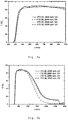
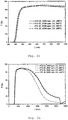
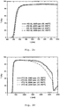
- Fig. 2a to Fig. 2e show transmission spectra in UV-VIS ( Fig. 2a . 2c . 2e ) and in the UV-VIS-NIR range ( Fig. 2b . 2d . 2f ) of ITO and ITO-TiO 2 layers.
- the ITO layers ITO 20 and ITO 30 were prepared with 20 wt.% Or 30 wt.% Strength ITO coating dispersion (see Tables 1, 1a, 1b), the ITO-TiO 2 layers ITS 05 and ITS 10 with a 20% ITO dispersion with 5 wt .-% and 10 wt .-% content of titanium compound (calculated as TiO 2 and based on ITO content in wt .-%, see Table 1a). All layers were spin coated at 2000 rpm. The curing of the layers was carried out by UV exposure either without further heat treatment ( Fig. 2a , b: samples 18, 22, 2, 6; see. Table 2) or by UV exposure and subsequent heat treatment at 240 ° C ( Fig.
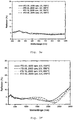
- Fig. 3a to Fig. 3e show reflection spectra in UV-VIS ( Fig. 3a . 3c . 3e ) and in the UV-VIS-NIR range ( Fig. 3b . 3d . 3f ) of the ITO and ITO TiO2 layers whose transmission spectra are in Fig. 2a to Fig. 2e (see description of the samples, see Fig. 2a to 2e ). It can be clearly seen that the reflection in the visible range by the content of TiO 2 . is hardly influenced The reflection in the NIR range (wavelength> 1500 nm) is for UV-cured samples ( Fig. 3a, 3b ) and for UV-cured samples with additional heat treatment at 240 ° C ( Fig.
Landscapes
- Chemical & Material Sciences (AREA)
- Engineering & Computer Science (AREA)
- Materials Engineering (AREA)
- Chemical Kinetics & Catalysis (AREA)
- Inorganic Chemistry (AREA)
- Physics & Mathematics (AREA)
- Thermal Sciences (AREA)
- General Chemical & Material Sciences (AREA)
- Nanotechnology (AREA)
- Mechanical Engineering (AREA)
- Metallurgy (AREA)
- Organic Chemistry (AREA)
- Paints Or Removers (AREA)
- Laminated Bodies (AREA)
- Application Of Or Painting With Fluid Materials (AREA)
- Manufacturing Of Electric Cables (AREA)
Description
- Die Erfindung betrifft Beschichtungen auf der Basis von Indium-Zinn-Oxid.
- Indium-Zinn-Oxide sind durch ihre optoelektronischen Eigenschaften gekennzeichnet. Sie sind z. B. in Form von dünnen transparenten Schichten in der Lage, Infrarotlicht zu reflektieren und zeichnen sich gleichzeitig durch eine relativ hohe elektronische Leitfähigkeit bei vorhandener Transparenz in Schichtsystemen aus.
- Aus diesem Grunde gibt es sehr viele Anwendungsmöglichkeiten für Indium-Zinn-Oxid (ITO)-Systeme, und dementsprechend auch sehr viele Untersuchungen zu ihrer Herstellung.
- Die gängigsten Verfahren zum Auftragen von transparenten Schichten sind Gasphasentechniken, bei denen das ITO aus der Gasphase auf das Substrat in Form einer zusammenhängenden dünnen Schicht abgeschieden wird. Als andere Verfahren werden der Sol-Gel-Prozess oder Pulver- und Pastentechnologien verwendet.
- Das Stoffsystem Indium und Sauerstoff ist durch eine Vielzahl von Verbindungen gekennzeichnet. Die thermodynamisch stabilste ist In2O3. Indiumoxide der Zusammensetzung In4O3, In4O5, In2O und In7O9 werden üblicherweise durch Reduktion von In2O3 in Wasserstoffstrom gebildet. In2O3 ist bei Zimmertemperatur dunkelgelb bis hellgelb, bei höheren Temperaturen braun bis braunrot und in Mineralsäuren löslich. Röntgenographisch kann nur die kubische Modifikation nachgewiesen werden.
- Indiumoxid ist ein wide-gap n-Halbleiter, dessen intrinsische Elektronenleitung auf Sauerstofffehlstellen beruht. Die Mobilität der Ladungsträger wird neben intrakristallinen Effekten vor allem durch die Behinderung interkristalliner Elektronenübergänge beschränkt. Eine Möglichkeit, die geringe Ladungsträgerdichte des reinen Indiumoxids zu erhöhen, ist der gezielte Einbau von vierwertigen Elementen wie z. B. Zinn.
- In den letzten Jahren hat das Interesse an einer definierten Herstellung und Anwendung transparenter leitfähiger Schichten auf verschiedenen Substraten stark an Bedeutung gewonnen. Während die Anwendung Sb-und F-dotierter Zinnoxidschichten auf Glassubstraten aufgrund ihrer Leitfähigkeit, ihrer Transparenz im sichtbaren Spektralbereich und ihrer Reflektionseigenschaften im IR-Bereich für die Oberflächenbeheizung von Gläsern für Flugzeuge, Raumschiffe, Kameras und auch für elektrostatische Abschirmzwecke schon lange bekannt ist, sind in neuerer Zeit vielfältige Anforderungen an derartige Schichten für die Anwendungen in der Mikro- und Optoelektronik entstanden. Dazu gchören z. B.
- 1. transparente Ansteuerelektroden für Flüssigkeitsdisplays, Dünnfilmelektrolumineszenz-Displays und Elektrochromie-Displays.
- 2. transparente leitfähige Schichten für hochempfindliche Strahlungsdetektoren, ferroelektrische Photoleiter und Speicheranordnungen.
- 3. transparente leitfähige Oxidfilme als Gate-Elektroden für Ladungs-, Injektions- und ladungsgekoppelte Anordnungen.
- Diese Anwendungen in der Optoelektronik sind gleichfalls mit höheren Anforderungen an die Leitfähigkeit, Transparenz und Strukturierbarkeit der Schichten verbunden. Aufgrund der ungünstigen Strukturierungseigenschaften dotierter Zinnoxidschichten bei der üblichen Strukturierung durch chemische Ätztechnologien haben sich für diese Anwendungen überwiegend zinndotierte Indiumoxidschichten (ITO) durchgesetzt.
- Weiterhin zeigen diese ITO-Schichten im Vergleich zu dotierten Zinnoxidschichten eine wesentlich bessere Leitfähigkeit und Transparenz. Zinndotierte Indiumoxidschichten stellen zurzeit die leitfähigsten Beschichtungen dar, die kommerziell erhältlich sind. Im Routinebetrieb liegt der erreichbare spezifische Widerstand bei etwa 1-2 x 10⁴ Ohm.cm, was in Verbindung mit einer etwa 30 nm dicken Sperrschicht aus SiO2 bereits bei 120 nm Schichtdicke zu einem Flächenwiderstand von 15 Ohm/sq führt. (Transparenz > 90%). Bedingt durch die Herstellung im Sputter- bzw. CVD-Verfahren sind die Kosten für diese Art der Beschichtung vergleichsweise hoch und großflächige Beschichtungen sind nur schwer durchzuführen.
- Die hohe Ladungsträgerdichte in Verbindung mit einer Ladungsträgermobilität im Bereich von 40-60 cm2/Vs führt zu einer sehr hohen Transparenz im sichtbaren Bereich, bei gleichzeitig hervorragender Reflexion im IR-Bereich. Der Anteil an Zinnoxid liegt üblicherweise zwischen 7-12 Gew. %.
-
US 5,518,810 betrifft die Herstellung von speziellen IRblockierenden Materialien auf ITO-Basis insbesondere in Polymeren. -
JP 8 067837 DE 198 49 048 offenbaren Verfahren zur Herstellung einer Beschichtung unter Verwendung einer Zusammensetzung enthaltend ITO-Partikel. - Zur Herstellung von leitfähigen und/oder transparenten Beschichtungen auf ITO-Basis werden daher häufig Suspensionen von ITO-Partikeln verwendet. Um dabei eine hohe Transparenz zu gewährleisten ist es notwendig, dass die eingesetzten Partikel nicht nur eine durchschnittliche Teilchengröße von nicht mehr als 200 nm aufweisen, sondern auch, dass sie in der Suspension im wesentlichen keine Agglomerate bilden, sondern die Primärpartikelgröße praktisch erhalten bleibt.
- Aus Kostengründen ist gerade für die Massenherstellung ein möglichst geringer Gehalt an Indium von großem Interesse.
- Da gerade in der Optoelektronik sehr hohe Anforderungen an die eingesetzten Materialien gestellt werden, reichen die Zusammensetzungen aus dem Stand der Technik nicht aus, um transparente und/oder leitfähige Schichten auf ITO-Basis mit verringertem Indiumgehalt herzustellen. In der aktuellen Entwicklung spielt gerade die Leitfähigkeit von besonders dünnen Schichten eine wichtige Rolle.
- Aufgabe der Erfindung ist es, ein Verfahren zur Herstellung von Beschichtungen auf Indium-Zinn-Oxid-Basis anzugeben, welches es erlaubt transparente und/oder leitfähige Schichten mit sehr vorteilhaften Eigenschaften und reduziertem Gehalt an Indium herzustellen.
- Diese Aufgabe wird durch die Erfindungen mit den Merkmalen der unabhängigen Ansprüche gelöst. Vorteilhafte Weiterbildungen der Erfindungen sind in den Unteransprüchen gekennzeichnet. Der Wortlaut sämtlicher Ansprüche wird hiermit durch Bezugnahme zum Inhalt dieser Beschreibung gemacht. Die Erfindung umfasst auch alle sinnvollen und insbesondere alle erwähnten Kombinationen von unabhängigen und/oder abhängigen Ansprüchen.
- Im Folgenden werden einzelne Verfahrensschritte näher beschrieben. Die Schritte müssen nicht notwendigerweise in der angegebenen Reihenfolge durchgeführt werden, und das zu schildernde Verfahren kann auch weitere, nicht genannte Schritte aufweisen.
- Die Aufgabe wird überraschenderweise durch ein Verfahren zur Herstellung von Beschichtungen und/oder Formkörpern auf der Basis von Indium-Zinn-Oxid (ITO) enthaltend folgende Schritte gelöst:
- a) Herstellung einer Zusammensetzung enthaltend
- a1) ITO-Nanopartikel; und
- a2) mindestens eine hydrolysierbare Verbindung der 4., 5., 6., 13. oder 14. Gruppe des Periodensystems;
- a3) mindestens ein organisch modifiziertes anorganisches Bindemittel;
- b) Auftragen der Beschichtungszusammensetzung auf ein Substrat oder Einbringen der Zusammensetzung in einer Form;
- c) Härten der Zusammensetzung.
- Es wurde gefunden, dass durch das angegebene Verfahren erhaltene Beschichtungen oder Formkörper eine verbesserte spezifische Leitfähigkeit oder Transparenz wie Beschichtungen oder Formkörper aus Zusammensetzungen nur aus ITO aufweisen. Dabei werden Beschichtungen oder Formkörper verglichen, welche aus Zusammensetzungen mit dem ähnlichem Anteil in Gew.-% an ITO hergestellt wurden. Durch die Erfindung können Beschichtungen und Formkörper mit verringertem Gehalt an ITO hergestellt werden, welche gleiche oder verbesserte Eigenschaften aufweisen. Von besonderer Bedeutung ist dabei die Leitfähigkeit der hergestellten Beschichtungen und Formkörper. Zusätzlich werden die optischen Eigenschaften kaum verändert.
- Unter Indium-Zinn-Oxid-Nanopartikeln werden Nanopartikel verstanden, welche im Wesentlichen aus einem Mischoxid von Indium und Zinn bestehen. Das Indium und das Zinn können darin in einer oder in verschiedenen Oxidationsstufen vorliegen. Beispielsweise liegen In (+I) und/oder In (+III) sowie Sn (+II) und/oder Sn (+IV) vor. Sn liegt bevorzugt als Sn (+IV) vor. Gegebenenfalls können Indium und Zinn auch teilweise als In (0) oder Sn (0) vorliegen. Die ITO-Nanopartikel können auch oberflächenmodifiziert sein.
- Bevorzugt handelt es sich bei dem ITO-Pulver um ein zinndotiertes Indiumoxid, d. h. der Anteil an Zinnoxid ist geringer als der Anteil an Indiumoxid. Der Anteil an Zinnoxid bezogen auf das Indium-Zinn-Oxid, ohne Berücksichtigung der oberflächenmodifizierenden Komponenten, beträgt beispielsweise 2 bis 30 Mol-%, bevorzugt 5 bis 12 Mol-%. Die ITO-Nanopartikel können beispielsweise, ohne Berücksichtigung der oberflächenmodifizierenden Komponente, durch die Formel In2-ySnyO3 mit 0 ≤ y ≤ 2 insbesondere 0 ≤ y ≤ 1 ausgedrückt werden (Ladungsüberschuss: e- y).
- Selbstverständlich kann das Indium-Zinn-Oxid-Pulver Verunreinigungen enthalten.
- Der akzeptierbare Grad hängt vom Verwendungszweck ab. Über die Edukte kann z. B. SO4 2- , Co, Cu, Fe, Ni, Pb, Zn, K oder Na enthalten sein. Durch Verwendung reiner Edukte können SO4 2-, Ca, Co, Cu, Fe, Ni, Pb und Zn auf unter 0,005 Gew.-% und Na, K auf unter 0,01 Gew. % gebracht werden. Über das Verfahren kann z. B. NH4 + und Cl- in das Produkt gelangen, das je nach Anzahl der Waschzyklen praktisch gänzlich entfernt werden kann. Bezogen auf das Indium-Zinn-Oxid-Pulver sind aber unter Berücksichtigung der oberflächenmodifizierenden Komponente weniger als 5 Gew.-%, bevorzugt weniger als 1 Gew.-%, insbesondere bevorzugt weniger als 0,1 Gew.-% Verunreinigungen enthalten.
- Die ITO-Nanopartikel weisen bevorzugt eine durchschnittliche Teilchengröße von bevorzugt nicht mehr als 200 nm, insbesondere nicht mehr als 50 nm und besonders bevorzugt nicht mehr als 30 nm auf. Ein besonders bevorzugter Bereich liegt bei 5 bis 30 nm.
- Bevorzugt sind ITO-Nanopartikel, welche durch Fällung von Indium-Zinn-Vorstufen in Gegenwart einer oder mehrerer oberflächenmodifizierender Komponenten, nachträglicher Calcinierung und folgender Zerkleinerungs- oder Dispergierbehandlung erhalten werden.
- Als oberflächenmodifizierende Komponenten können beispielsweise Mono- oder Polycarbonsäuren, Diketone, Aminosäuren, Polyethylenoxidderivate, Amine oder Säureamide oder Mischungen aus zwei oder mehreren dieser Komponenten eingesetzt werden.
- Beispiele für weitere geeignete oberflächenmodifizierenden Komponenten sind Mono- und Polyamine, insbesondere solche der allgemeinen Formel R3-nNHn, worin n = 0,1 oder 2 und die Reste R unabhängig voneinander Alkylgruppen mit 1 bis 12, insbesondere 1 bis 6 und besonders bevorzugt 1 bis 4 Kohlenstoffatomen darstellen (z. B. Methyl, Ethyl, n-und i-Propyl und Butyl) und Polyethylenamine ; β-Dicarbonylverbindungen mit 4 bis 12, insbesondere 5 bis 8 Kohlenstoffatomen ; Organoalkoxysilane, wie z. B. diejenigen, die zur Oberflächenmodifizierung von kolloidaler Kieselsäure eingesetzt werden (z. B. solche der aligemeinen Formel R4-mSi(OR')m worin die Gruppen R und R' unabhängig voneinander C1-C4-Alkyl darstellen und m 1, 2, 3 oder 4 ist und modifizierte Alkoholate, bei denen ein Teil der OR-Gruppen (R wie oben definiert) durch inerte organische Gruppen substituiert ist und über die noch vorhandenen OR-Gruppen eine Anbindung (Kondensation) auf der Partikeloberfläche erfolgt und die organischen Gruppen die Abschirmung übernehmen. Beispiele hierfür sind z. B. Zirkon-und Titanalkoholate M(OR)4 (M = Ti, Zr), bei denen ein Teil der OR-Gruppen durch einen Komplexbildner, wie z. B. eine β-Dicarbonylverbindung oder eine (Mono)carbonsäure ersetzt ist.
- Eine weitere Gruppe von verwendbaren oberflächenmodifizierenden Komponenten sind Tenside, z. B. kationische, anionische, nicht-ionische und amphotere Tenside.
- Bevorzugt werden nicht-ionische Tenside, wobei Polyethylenoxid-derivate besonders bevorzugt sind. Es kann sich dabei z. B. um Derivate mit gesättigten oder ungesättigten (Mono)carbonsäuren handeln, insbesondere mit Carbonsäuren mit mehr als 7, bevorzugt mehr als 11 Kohlenstoffatomen, z. B. Polyethylenoxidderivate mit Stearin-, Palmitin- oder Ölsäure, etwa die unter der Marke "Emulsogen" erhältlichen Produkte. Es kann sich auch um Derivate mit Sorbitanestern (Sorbitan + Carbonsäure) handeln, wobei als Carbonsäure beispielsweise die vorstehend genannten in Frage kommen. Diese Produkte sind im Handel unter der Marke "Tween" erhältlich. Weiter können Polyethylenoxid(mono)-alkylether, beispielsweise mit Alkoholen mit mehr als 7, bevorzugt mehr als 11 Kohlenstoffatomen verwendet werden, z. B. die unter der Marke "Brij" erhältlichen Produkte.
-
- a. Mono- und Polycarbonsäuren wie Ameisensäure, Essigsäure, Propionsäure, Buttersäure, Pentansäure, Hexansäure, Acrylsäure, Methacrylsäure, Crotonsäure, Citronensäure, Adipinsäure, Bernsteinsäure, Glutarsäure, Oxalsäure, Maleinsäure, Fumarsäure, Itaconsäure, Stearinsäure und insbesondere 3,6,9-Trioxadecansäure sowie die entsprechenden Anhydride,
- b. Diketone wie Acetylaceton, 2,4-Hexandion, 3,5-Heptandion, Acetessigsäure, Acetessigsäure-C1-C4-Alkylester wie Acetessigsäureethylester, Diacetyl und Acetonylaceton,
- c. Aminosäuren, insbesondere β-Alanin, aber auch Glycin, Valin, Aminocapronsäure, Leucin und Isoleucin,
- d. Polyethylenoxid-Derivate, insbesondere Tween 80 (Sorbitanmonooleat-polyoxyalkylen), aber auch Emulsogen® (Hexaglycolmonostearat), Emulsogen® OG (Ölsäurederivat) und Brij® 30 (Polyoxyethylenlaurylether),
- e. Säureamide, insbesondere Caprolactam, und
- f. Amine wie z. B. Methylamin, Dimethylamin. Trimethylamin, Anilin, N-Methylanilin, Diphenylamin, Triphenylamin, Toluidin, Ethylendiamin, Diethylentriamin.
- Diese oberflächenmodifizierenden Komponenten können einzeln oder als Mischung eingesetzt werden. Besonders bevorzugte Verbindungen sind 3,6,9-Trioxadecansäure, β-Alanin, Tween® 80 und Caprolactam.
- Der Anteil der oberflächenmodifizierenden Komponente(n), bezogen auf die ITO-Partikel, liegt bevorzugt zwischen 2 und 30 Gew.-%, besonders bevorzugt zwischen 2 und 7 Gew.-%.
- Die nach der Fällung erhaltenen Partikel werden calciniert, beispielsweise bei Temperaturen zwischen 200 und 400 °C, bevorzugt zwischen 230 und 280 °C, besonders bevorzugt bei 250 °C. Die isotherme Haltezeit beträgt beispielsweise zwischen 15 und 120 Minuten, bevorzugt zwischen 45 und 90 Minuten, besonders bevorzugt 60 Minuten. Die Calcinierung erfolgt bevorzugt unter reduzierenden Bedingungen, wobei ebenfalls die vorstehend benannten Verfahrensbedingungen zur Anwendung kommen. Die reduzierenden Bedingungen werden bevorzugt durch Durchleiten eines reduzierenden Gases/Gasgemisches oder eines reduzierenden Dampfes erhalten. Vor Einsatz der reduzierenden Komponente kann der Ofen mit einem Inertgas, z. B. Stickstoff gespült werden. Als reduzierendes Gas/Gasgemisch oder reduzierender Dampf kann beispielsweise Kohlenmonoxid, Kohlenmonoxid/ Stickstoff, eine Wasserdampf-Atmosphäre oder Formiergas (Wasserstoff/Stickstoff) verwendet werden. Dabei ist die Verwendung von Formiergas besonders bevorzugt. Der eingesetzte Gasfluss hängt von der Menge des zu calcinierenden Pulvers und der reduzierenden Komponente ab.
- Falls die Calcinierung nicht unter reduzierenden Bedingungen durchgeführt wurde, kann die Reduktion auch nach der Calcinierung durchgeführt werden, beispielsweise in einem späteren Verfahrensschritt des erfindungsgemäßen Verfahrens.
- Die bevorzugten ITO-Nanopartikel werden danach durch eine Zerkleinerungs- oder Dispergierbehandlung aus dem calcinierten Pulver erhalten, wobei weitere oberflächenmodifizierende Komponenten und/oder weitere Lösungsmittel zugegeben werden. Bevorzugt handelt es sich um eine mechanische Zerkleinerungsbehandlung. Bevorzugt ist außerdem der Zusatz oberflächenmodifizierender Komponenten, insbesondere 3,6,9-Trioadecansäure. Bezogen auf das calcinierte Pulver wird die oberflächenmodifizierende Komponente, bevorzugt in einer Menge von 2 bis 30 Gew.-%, besonders bevorzugt von 2-10 Gew.-% zugegeben.
- Bei der Zerkleinerungsbehandlung kann auch noch ein oder mehrere Lösungsmittel zugegeben werden. Bevorzugt werden als Lösungsmittel hochsiedende Flüssigkeiten, z.B. Flüssigkeiten mit einem Siedepunkt von über 120 °C, bevorzugt über 150 °C. Bevorzugt werden hochsiedende Glycole oder Glycolether eingesetzt, bevorzugt Ethylen-, Propylen- oder Butylenglycol oder die entsprechenden Di-, Tri-, Tetra-, Penta- oder Hexamere, sowie die entsprechenden Mono- oder Diether wobei eine oder beide Hydroxygruppen durch z.B. eine Methoxy-, Ethoxy-, Propoxy- oder Butoxygruppe ersetzt sind. Selbstverständlich können auch Mischungen dieser Lösungsmittel eingesetzt werden.
- Das Lösungsmittel kann bei der Zerkleinerung oder Dispergierung bezogen auf das eingesetzte Indium-Zinn-Oxid-Pulver, in einer Menge von 5 bis 150 Gew.-%, bevorzugt 10 bis 100 Gew.-%, besonders bevorzugt zwischen 30 bis 50 Gew.-% zugegeben werden. Ein besonders bevorzugtes Verhältnis ist 75:25. Bevorzugt wird die Menge des Lösungsmittels so gewählt, dass pastöse, bzw. hochviskose Suspensionen erhalten werden. Alternativ können auch durch Entfernen des Lösungsmittels Pulver erhalten werden.
- Auf diese Weise hergestellte Partikel zeichnen sich insbesondere dadurch aus, dass sie im Wesentlichen auf Primärgröße redispergierbar.sind.
- Solche Partikel sind beispielsweise in der Schrift
WO 00/14017 A1 - Die Zusammensetzung enthält eine hydrolysierbare Verbindung der Gruppen 4., 5., 6., 13. oder 14. des Periodensystems. Die Zusammensetzung kann 1 bis 80 Gew.-% dieser Verbindung bezogen auf den Gehalt an ITO enthalten, bevorzugt sind 1 bis 30 Gew.-%, besonders bevorzugt sind 3 bis 15 Gew.-%, insbesondere 5 bis 10 Gew.-% bezogen auf den ITO Gehalt, wobei der optimale Gehalt an dieser Verbindung vom ITO Gehalt abhängt, da er auf den ITO Gehalt bezogen wird. Abhängig vom Gehalt an ITO kann der optimale Bereich variieren. Bevorzugt wird der Gehalt der hydrolysierbaren Verbindung auf das ihr entsprechende Oxid bezogen, z.B. im Falle von Ti(OR)4 auf TiO2). Dies ist in der Regel das Oxid der stabilsten Oxidationsstufe dieser Verbindung. Bevorzugt handelt es sich dabei um Verbindungen der Formel MXa, wobei M ein Metall der 4., 5., 6., 13. oder 14. des Periodensystems ist (Si ist dabei kein Metall), wie beispielsweise B, Al, Ga, In, Tl, Ge, Sn, Pb, Ti, Zr, Hf, V, Nb, Ta, Cr, Mo, W. Bevorzugt ist M Sn, Ti, Al oder Zr, besonders bevorzugt Ti. X ist ein hydrolysierbarer Rest, wie beispielweise Halogenatome (insbesondere Chlor und Brom), Alkoxygruppen, Alkylcarbonylgruppen oder Acyloxygruppen, wobei Alkoxygruppen, insbesondere C1-4-Alkoxygruppen, besonders bevorzugt Ethoxy-, Propoxy-, Isopropoxy-, n-Butoxy-, iso-Butoxy-Gruppen, bevorzugt sind. a entspricht der Wertigkeit von M. Bevorzugt eingesetzte Titanate sind Ti(OCH3)4, Ti(OC2H5)4 und Ti (n-oder i-OC3H7)4. Es können auch Mischungen eingesetzt werden.
- Der Gehalt an ITO-Partikeln in der gehärteten Schicht oder dem gehärteten Formkörper liegt bevorzugt bei über 70 Gew.-%, besonders bevorzugt über 75 Gew.-% oder über 80 Gew.-%, aber unter 95 Gew.-% oder unter 90 Gew.-%, insbesondere zwischen 70 Gew.-% und 95 Gew.-%, bevorzugt zwischen 75 Gew.-% und 90 Gew.-%. Bei Verwendung eines organisch modifizierten anorganischen Bindemittels bezogen auf die anorganischen Bestandteile des Bindemittels. Unter anorganischen Bestandteilen wird dabei das Oxid des Bindemittels und das Oxid der hydrolysierbaren Verbindung verstanden.
- Die ITO-Nanopartikel und die hydrolysierbare Verbindung können auf beliebige dem Fachmann bekannte Arten miteinander vermischt werden. Bevorzugt ist die Vermischung einer Dispersion oder eines Sols der ITO-Partikel und die eines Sols der hydrolysierbaren Verbindung. Die ITO-Nanopartikel können sowohl direkt aus dem Herstellungsverfahren, als auch als Pulver hinzugefügt werden. Als Lösungsmittel können geeignete dem Fachmann bekannte Lösungsmittel verwendet werden. Bevorzugt sind organische Lösungsmittel. Als organische Lösungsmittel eignon sich sowohl polare als auch unpolare und aprotische Lösungsmittel. Beispiele hierfür sind Alkohole, wie z. B. aliphatische Alkohole mit 1 bis 6 Kohlenstoffatomen (insbesondere Methanol, Ethanol, n-und i-Propanol, 2-Isopropoxyethanol und Butanol); Ketone, wie z. B. Aceton und Butanon ; Ester, wie z. B. Essigsäureethylester ; Ether, wie z. B. Diethylether, Tetrahydrofuran und Tetrahydropyran ; Amide, wie z. B. Dimethylacetamid und Dimethylformamid ; Sulfoxide und Sulfone, wie z. B. Sulfolan und Dimethylsulfoxid ; und aliphatische (gegebenenfalls halogenierte) Kohlenwasserstoffe, wie z. B. Pentan, Hexan und Cyclohexan. Selbstverständlich können auch Mischungen derartiger Lösungsmittel eingesetzt werden.
- Abhängig von der Verwendung der Zusammensetzung können auch noch nach der Vermischung Lösungsmittel entfernt oder hinzugefügt werden, beispielsweise um eine bestimmte Viskosität einzustellen.
- Zusätzlich kann die Zusammensetzung noch übliche Additive, wie Benetzungsmittel, Stabilisatoren, Sensibilisatoren oder ähnlich enthalten, bevorzugt unter 5 Gew.-% bezogen auf die Zusammensetzung.
- Die Zusammensetzung kann noch zusätzlich noch ein oder mehrere Bindemittel enthalten. Die Bindemittel können in einer Menge zugegeben werden, dass der Füllgrad an ITO und dem Hydrolyseprodukt der hydrolysierbaren Verbindung von 1 bis 95 Vol.-%, bevorzugt 5 bis 80 Vol.-% ergibt. Unter Füllgrad wird dabei die Menge an ITO und Oxid der hydrolysierbaren Verbindung in Vol.-% bezogen auf den Gesamtfeststoffgehalt der nach Härtung, bzw. Trocknung der Zusammensetzung verstanden. In der gehärteten, bzw. getrockneten Zusammensetzung kann der Gehalt an Bindemittel bezogen auf die anorganischen Bestandteile zwischen 1 und 20 Gew.-% der Schicht betragen, bevorzugt zwischen 3 und 10 Gew.-% bezogen auf das Oxid des jeweiligen Bindemittels (z. B. SiO2 im Falls von Silanen).
- Dabei kann beispielsweise auch das Bindemittel bereits bei der Zerkleinerungsbehandlung der bevorzugten ITO-Nanopartikel zugegeben werden. Prinzipiell kann das Bindemittel, sofern es eine geeignete Viskosität aufweist, auch anstelle eines Lösungsmittels verwendet werden.
- Als Bindemittel können prinzipiell alle dem Fachmann bekannten organisch modifizierten anorganischen Bindemittel oder Mischungen davon eingesetzt werden. Beispiele für organisch modifizierte anorganische Bindemittel sind Polyorganosiloxane bzw. Silicon-Lacke. Die Polyorganosiloxane bzw. die Silicon-Lacke werden bevorzugt nach dem Sol-Gel- Verfahren hergestellt (Sol-Gel-Lack). Zur Herstellung werden bevorzugt hydrolysierbare Silane verwendet. Die hydrolysierbaren Silane können bevorzugt nicht hydrolysierbare Reste aufweisen. Das organisch modifizierte anorganische Bindemittel umfasst daher mindestens ein hydrolysierbares Silan mit mindestens einem nicht hydrolysierbaren Rest.
- Bei den hydrolysierbaren Silanen handelt es sich bevorzugt um Silane der allgemeinen Formel RnSiX4-n. Bei der oder den Gruppen X, die gleich oder verschieden sein können, und vorzugsweise identisch sind, handelt es sich um hydrolysierbare Reste, bei R handelt es sich um nicht hydrolysierbare Reste. Die Reste X werden vorzugsweise aus Halogenatomen (insbesondere Chlor und Brom), Alkoxygruppen, Alkylcarbonylgruppen und Acyloxygruppen ausgewählt, wobei Alkoxygruppen, insbesondere C1-4-Alkoxygruppen wie Methoxy und Ethoxy besonders bevorzugt sind. n kann die Werte 1, 2 oder 3, vorzugsweise 1 oder 2 und besonders bevorzugt 1, annehmen. Die eingesetzten hydrolysierbaren Silane können auch vollständig hydrolysierbare Silane der obigen Formel, in der n gleich 0 ist, umfassen, vorzugsweise in einem Anteil von weniger als 50 Mol-% auf Basis aller eingesetzten monomeren hydrolysierbaren Silane.
- Die Gruppe R oder die Gruppen R, die gleich oder verschieden sein können, können Alkyl, Alkenyl, Aryl, Alkylaryl, Arylalkyl oder R'Y sein. R' ist geradkettiges oder verzweigtes Alkylen, durch Sauerstoff-oder Schwefelatome oder NH-Gruppen unterbrochen sein kann, Phenylen, Alkylphenylen oder Alkylenphenylen. Y ist die funktionelle Gruppe, über die eine Vernetzung möglich ist. Beispiele für Y sind gegebenenfalls substituierte Amino-, Amid-, Alkylcarbonyl, gegebenenfalls substituierte Anilino-, Aldehyd-, Keto-, Carboxyl-, Hydroxyl-, Alkoxy-, Alkoxycarbonyl, Mercapto-, Cyano-, Hydroxyphenyl-, Carbonsäurealkylester-, Sulfonsäure-, Phosphorsäure-, Acryloxy-, Methacryloxy-, Glycidyloxy-, Epoxid-, Hydroxyl-oder Aminogruppen. Gruppe R ist bevorzugt ein (Meth) acryloxy-(C1-6)-alkylen-Rest wie z. B. (Meth) acryloxypropyl. Konkrete Beispiele für Silane sind Vinyltriethoxysilan, Vinyltrimethoxysilan, Methacryloxypropyltrimethoxysilan (MPTS), Methacryloxypropyltriethoxysilan, Acryloxypropyltrimethoxysilan und Acryloxypropyltriethoxysilan, wobei MPTS mit Vorteil eingesetzt wird. Weitere Beispiele für Epoxysilane sind 3- Glycidyloxypropyltrimethoxysilan (GPTS) oder 3-Glycidyloxypropyltriethoxysilan.
- In den vorstehenden Formeln können mehrmals vorhandene Reste R, R', X bzw. Y bei einer Verbindung jeweils die gleiche oder unterschiedliche Bedeutung haben. Es können auch Mischungen verschiedener hydrolysierbarer Silane verwendet werden.
- Beispiele für anorganische Bindemittel sind Silicon-Lacke, die z. B. aus hydrolysierbaren Silanen hergestellt werden, die keine nicht-hydrolysierbaren Substituenten aufweisen, also z. B. Verbindungen der obigen Formel RnSiX4-n, worin n = 0 und X wie vorstehend definiert ist.
- Bevorzugt weist die Zusammensetzung nur ein oder mehrere organisch modifizierte anorganische Bindemittel auf und keine organischen Bindemittel.
- Bevorzugt sind Bindemittel, welche vernetzbare Gruppen enthalten, bevorzugt weist der nicht hydrolysierbare Rest mindestens eine funktionelle Gruppe auf, über die eine Vernetzung möglich ist. Abhängig von der Vernetzungsreaktion können noch entsprechende Initiatoren oder Katalysatoren zugesetzt werden. Als Katalysatoren/Initiatoren bzw. Vernetzungsinitiator kommen alle geläufigen und dem Fachmann bekannten Starter/Startsysteme in Frage, einschließlich radikalischer Photostarter, radikalischer Thermostarter, kationischer Photostarter, kationischer Thermostarter und beliebiger Kombinationen derselben.
- Unter bestimmten Umständen kann ganz auf den Vernetzungsinitiator verzichtet werden, wie z. B. gegebenenfalls im Fall von Elektronenstrahl- oder Laserhärtung.
- Konkrete Beispiele für einsetzbare radikalische Photostarter sind Irgacure ® 184 (1-Hydroxycyclohexylphenylketon),Irgacure ® 500 (1-Hydroxycyclohexylphenylketon, Benzophenon), Irgacure ® 819 (phosphine oxide, phenyl bis (2,4,6-trimethyl benzoyl) und andere von der Firma Ciba-Geigy erhältliche Photoinitiatoren vom Irgacure®-Typ, Darocure 1173, 1116, 1398, 1174 und 1020 (Fa. Merck), Benzophenon, 2-Chlorthioxanthon,2-Methylthioxanthon,2-Iso-propylthioxanthon, Benzoin, 4,4'-Dimethoxybenzoin, Benzoinethylether, Benzoinisopropylether, Benzildimethylketal, 1,1,1-Trichloracetophenon, Diethoxyacetophenon und Dibenzosuberon.
- Beispiele für radikalische Thermostarter sind bevorzugt organische Peroxide in Form von Diacylperoxiden, Peroxydicarbonaten, Alkylperestern, Alkylperoxiden, Dialkylperoxiden, Perketalen, Ketonperoxiden und Alkylhydroperoxiden sowie Azo-Verbindungen. Als konkrete Beispiele wären hier insbesondere Dibenzoylperoxid, tert-Butylperbenzoat und Azoisobutyronitril zu nennen. Ein Beispiel für einen kationischen Photostarter ist Cyracure® UVI-6974, während ein bevorzugter kationischer Thermostarter 1-Methylimidazol ist.
- Die Polykondensation induzierende Katalysatoren sind z. B. Brönsted-Säuren und -Basen, wie Mineralsäuren oder tertiäre Amine, für die anionische Polykondensation und Lewis-Säuren, wie Metallalkoholate (z. B. Aluminiumalkoholate im Falle von Epoxysilanen), für die kationische Polykondensation. Bei Beteiligung von Epoxidgruppen ist der Zusatz von Ringöffnungskatalysatoren wie beispielsweise N-Alkylimidazolen von besonderem Vorteil.
- In einer bevorzugten Ausführungsform wird die hydrolysierbare Verbindung oder ein Sol der hydrolysierbaren Verbindung zu einem Sol enthaltend ITO-Nanopartikel, Bindemittel und evtl. Additive oder Initiatoren/Katalysatoren gegeben. Bevorzugt wird ein Sol des Bindemittels, im Falle von Silanen bevorzugt ein durch saure Katalyse erhaltenes Sol (oder Vorkondensat), zu einer Dispersion der ITO-Nanopartikel gegeben. Erst als letzte Komponente wird die hydrolysierbare Verbindung zugegeben.
- Bevorzugt sind Bindemittel, welche durch Hitze oder Bestrahlung, bevorzugt von UV-Licht härten lassen. Bevorzugt ist das Bindemittel ein Hydrolysat von Silanen mit vernetzbaren Gruppen, bevorzugt Silane mit Epoxid-, Methacrylat- oder Acrylatgruppen, besonders bevorzugt ein MPTS-Hydrolysat.
- Die Zusammensetzung wird danach einem Formgebungsprozess unterworfen. Dies beinhaltet die Herstellung von Beschichtungen, als auch das Einbringen in eine Form zur Herstellung von Formkörpern.
- Im Falle von Formkörpern lassen sich über die dem Fachmann bekannten Formgebungsverfahren Formkörper herstellen. Beispielsweise seien Extrusion, Schlickerguss, Spritzgießen, Elektrophorese, Foliengießen Siebdruck oder Tiefdruck (Gravurdruck) genannt.
- Es können dabei, je nach dem angewendeten Verfahren, auch Bindemittel eingesetzt werden. Als Bindemittel kommen z. B. die vorstehend genannten in Frage.
- Als Formkörper können z. B. Schichten oder Sinterkörper, insbesondere Targets hergestellt werden. Targets werden insbesondere beim Sputter-Verfahren zur Beschichtung von Substraten eingesetzt. Ein besonderer Vorteil der erfindungsgemäßen Zusammensetzungen besteht darin, die erhaltenen Formkörper bei ähnlicher spezifischer Leitfähigkeit einen geringeren Indiumanteil aufweisen.
- Formkörper finden als Bauteile oder Funktionskörper für leitfähige Systeme in der Opto- und Mikroelektronik oder als ITO-Quelle in Sputteranlagen Verwendung.
- Bevorzugt ist die Herstellung von Beschichtungen durch Auftragen der Zusammensetzung auf ein Substrat. Die zur Beschichtung geeigneten Verfahren sind die herkömmlichen und dem Fachmann bekannten. Beispiele hierfür sind Tauchen, Sprühen, Rakeln, Streichen, Bürsten und Schleudern. Zur Beschichtung eignen sich Substrate aus beliebigen Materialien, wie z. B. Kunststoff, Metall, Glas, Halbleiter (z. B. Siliciumwafer) oder Keramik.
- Im nächsten Schritt wird die Zusammensetzung gehärtet. Dies beinhaltet auch einfaches Trocknen der Zusammensetzung. Diese Temperaturbehandlung erfolgt bei Temperaturen zwischen 200 und 600 °C, bevorzugt bei Temperaturen zwischen 200 und 400 °C, besonders bevorzugt zwischen 210 und 260 °C.
- Falls die Zusammensetzung vernetzbare Bestandteile, beispielsweise entsprechende Bindemittel, aufweist, kann die Härtung auch eine Behandlung unter Bedingungen, welche die Vernetzung hervorrufen, erfolgen. Bevorzugt ist eine Temperaturbehandlung oder Bestrahlung. Im Falle einer Bestrahlung ist eine Bestrahlung mit UV-Licht bevorzugt.
- Es ist auch möglich, dass mehrere Behandlungen nacheinander oder gleichzeitig durch geführt werden. Bevorzugt ist, bei Verwendung eines entsprechenden Bindemittels, die Bestrahlung, bevorzugt mit UV-Licht, und nachfolgend eine Temperaturbehandlung bei Temperaturen zwischen 200 und 600 °C, wobei höhere Temperaturen eine weitere Verbesserung der Eigenschaften bewirken können. Dabei sind höhere Temperaturen zwischen 500 und 600 °C bevorzugt. Wie bereits erwähnt, zeichnen sich die durch das erfindungsgemäße Verfahren erhaltenen Beschichtungen durch einen verbesserten spezifischen Widerstand, bzw. spezifische Leitfähigkeit, aus, als Beschichtungen aus reinem ITO bei Verwendung von Beschichtungsdispersionen mit gleichen Gehalt an ITO (Gew.-%). Die so erhaltenen Schichten haben im Vergleich zu reinen ITO Schichten einen geringeren Anteil an ITO im Feststoffanteil und trotzdem einen verbesserten spezifischen Widerstand. Wobei verbessert bedeutet, dass der spezifische Widerstand der erfindungsgemäßen Schicht um über 20 %, bevorzugt über 30 % geringer ist. Das bedeutet, dass mit Schichten mit geringerem Feststoffgehalt an ITO, ein verbesserter spezifischer Widerstand erreicht werden kann und dadurch ITO eingespart werden kann. Dadurch sind die Schichten bei besserer Leitfähigkeit deutlich günstiger herzustellen. Ohne an eine bestimmte Theorie gebunden zu sein, könnte es sein, dass die Zugabe der hydrolysierbaren Verbindung den Ladungstransport zwischen den ITO-Nanopartikeln erleichtert und daher zu einer Verbesserung der Leitfähigkeit beiträgt. Dies scheint jedoch nur in einem bestimmten Anteil der Fall zu sein.
- Gleichzeitig weisen die erfindungsgemäßen Beschichtungen auch die optische Qualität der entsprechenden ITO-Schichten. So zeigen sie eine ähnliche Transmission, Trübung oder Klarheit wie analog hergestellte Beschichtungen aus ITO. Lediglich bei hohen Anteilen der hydrolysierbaren Verbindung können die Werte etwas geringer sein. Da die Leitfähigkeit der erhaltenen ITO-Schichten und Formkörper im Vordergrund steht, weisen die erhaltenen Beschichtungen und Formkörper zwar im Vergleich zu den entsprechenden ITO-Schichten ähnlich gute optische Qualitäten auf, aber selbst die ITO-Schichten erreichen nicht die beispielsweise in
US 5,518,810 beschriebenen IR-cutoff-Eigenschaften von größer 90% für Wellenlängen über 700 nm. So werden die in derUS 5,518,810 verwendeten ITO-Partikel unter inerter Atmosphäre, Druck und bei höheren Temperaturen hergestellt. - Die erhaltenen Schichten zeigen auch bei geringer Schichtdicke eine gute Leitfähigkeit (spezifischer Widerstand von unter 10 Ωcm sogar unter 2 Ωcm oder 1 Ωcm nach Temperaturbehandlung). Durch den geringeren Gehalt an ITO sind sie deutlich kostengünstiger herzustellen.
- Die Zugabe von entsprechenden Nanopartikeln anstatt einer hydrolysierbaren Verbindung führte zu keiner Verbesserung der Eigenschaften der erhaltenen Formkörper oder Beschichtungen.
- Desweiteren betrifft die Erfindung auch mit dem erfindungsgemäßen Verfahren hergestellte Beschichtungen oder Formkörper.
- Die erfindungsgemäß hergestellten Zusammensetzungen finden bevorzugt als Beschichtungsmaterial in der Opto- und Mikroelektronik oder für optische (transparente), IR-blockierende oder leitfähige Beschichtungen Verwendung.
- Außerdem können sie für Siebdruckpasten oder Tiefdruckpasten verwendet werden. Sie können beispielsweise bevorzugt eingesetzt werden für transparente Ansteuerelektroden für Flüssigkeitsdisplays, Dünnfilmelektrolumineszenz-Displays, organische Photodioden, Elektrochromie-Displays, transparente leitfähige Schichten für hochempfindliche Strahlungs-selektoren, ferroelektrische Photoleiter, Speicheranordnungen, transparente leitfähige Oxidfilme als Gate-elektroden für Ladungs-, Injektions- und ladungsgekoppelte Anordnungen, sowie zur Herstellung von Druckpasten, die sich für die Bedruckung von Glas, Keramik und Kunststoffen eignen, zur Abschirmung von elektromagnetischen Wellen, für IR-reflektierenden Schichten bzw. Kunststoffe, leitfähige Elektroden für Solarzellen oder antistatische Filme, z. B. für Fernsehröhren, Monitore und Kontaktbildschirme. Die Beschichtungen können zur IR-Blockierung und zur Antistatikausrüstung verwendet werden. Die IR- Blockierung kann z. B. durch IR-Absorption oder durch IR-Reflektion erfolgen.
- Weitere Einsatzmöglichkeiten ist die Verwendung für Plastikverscheibungen, IR-Sperren für Projektoren, IR-Sperren nach Lampen, IR-absorbierende Anstriche und Lacke, Wärmeschutzscheiben B. als Beschichtung von Glasscheiben für Backöfen), Sonnenkollektoren, Schichten auf Wärmetauschern, sowie transparente Wärmestrahlenabsorber auf Metallen, Glas, Keramiken und Kunststoffen, wie Anti(be)taubeschichtungen und heizbare Beschichtungen auf allen Substraten und Gegenständen (z. B. Fahrzeuge, Fenster, Fassaden, Instrumente, Verkehrsschilder, Hinweisschilder und Fenster von Kühlanlagen).
- Desweiteren betrifft die Erfindung auch Artikel, welche erfindungsgemäße Beschichtungen enthalten, sowie die Verwendung dieser Artikel in den vorstehend genannten Anwendungen.
- Die folgenden Beispiele erläutern die Erfindung, ohne sie zu beschränken.
- Weitere Einzelheiten und Merkmale ergeben sich aus der nachfolgenden Beschreibung von bevorzugten Ausführungsbeispielen in Verbindung mit den Unteransprüchen. Hierbei können die jeweiligen Merkmale für sich alleine oder zu mehreren in Kombination miteinander verwirklicht sein. Die Möglichkeiten, die Aufgabe zu lösen, sind nicht auf die Ausführungsbeispiele beschränkt. So umfassen beispielsweise Bereichsangaben stets alle - nicht genannten - Zwischenwerte und alle denkbaren Teilintervalle.
- Es wurde eine Dispersion von ITO-Partikeln (vorzugsweise hergestellt nach
WO 00/14017 - Die Dispersion wurde bei Raumtemperatur gerührt (ca.15 min bis 24 h, vorzugsweise 1 h bis 18 h, besonders bevorzugt 2 bis 6 h) und anschließend zur Beschichtung verwendet. Zur längeren Aufbewahrung der Dispersion über mehrere Tage bis Wochen sollte die Lagerung im Kühlschrank erfolgen.
- Die hergestellten Zusammensetzungen zeigen die Tabellen 1, 1a und 1b.
- Mit den hergestellten Zusammensetzungen wurden Substrate (vorzugsweise Glas, z.B. Borosilikatglas) mit Hilfe von spin-coating (Spin Coater Convac 1001) beschichtet. Tabelle 2 zeigt die bei unterschiedlichen Bedingungen hergestellten Beschichtungen. Darüber hinaus ist auch die Beschichtung von Kunststofffolien wie z.B. PET und PEN Folien, mittels Tiefdruck (bzw. Gravurdruck)(Labratester N.Schläfli Maschinen, Schweiz) möglich.
- Die hergestellten Schichten wurden durch Bestrahlung mit UV-Licht gehärtet (Die bevorzugte Bestrahlungsenergie liegt dabei zwischen ca. 7 und 70 J/cm2, was mit 1 bis 10 Durchläufen auf einem Fließband mit der Geschwindigkeit 1 m/min in einem UV-Belichtungsgerät UV-IR-Trockner (Typ UV-IR-Labortrockner, BE 25/120W/II+2, Firma Beltron) entspricht. Die in den Beispielen verwendete Bestrahlungsenergie betrug 70 J/cm2, gemessen mit einem UV-Integrator der Firma Beltron) was 10 Durchläufen entspricht. Die Lichtenergie, gemessen mit dem UV-Integrator der Firma Beltron beträgt pro Durchlauf mit der Bandgeschwindigkeit 1 m/min ca. 7 J/cm2.
- Im Falle einer thermischen Behandlung wurden die beschichteten Substrate in einem Ofen bevorzugt einem Umluftofen bei 240 °C bzw. 550 °C zwischen 30 Minuten und 2 h, bevorzugt 30 min bis 1 h gesintert. Die Aufheizrate betrug 2,5 K/min, die Endtemperatur wurde 1 h aufrechterhalten, das Abkühlen der Proben erfolgte im Ofen ohne aktive Kühlung (Umluft ohne Heizen). Die thermische Behandlung wurde ohne Schutzgas unter Luft durchgeführt. Auch ein kürzeres Ausheizen im einem bereits vorgeheizten Ofen ist möglich. Durch die Verwendung von Schutzgas oder reduzierenden Gasen (z.B. Formiergas) kann der spezifische Widerstand der Schichten noch weiter gesenkt werden.
- Von den erhaltenen Beschichtungen wurde der Schichtwiderstand mit einem Vierpunkt-Messgerät (Model RT-70, RG-7S, Napson Corporation) gemessen. Die Schichtdicke sowie der Brechungsindex wurde mit einem Spektral-Ellipsometer (Spectroscopic Ellipsometer, ESM-300, J.A. Woollam Co., Inc) bestimmt, wobei für verschiedene Sintertemperaturen unterschiedliche Fitting Modelle zur Bestimmung der Schichtdicke ausgewählt wurden (Fitting Modell EMA für Temperaturen bis 250 °C und Cauchy für Sintertemperatur 550 °C).
- Zusätzlich wurde von den erhaltenen Beschichtungen nach der entsprechenden UV- bzw. kombinierten UV- und thermischen Behandlung Transmission, Haze (Trübung) und Clarity in Anlehnung an ASTM D1003 bestimmt bei Raumtemperatur (Haze-Gard plus, BYK Gardner). Von ausgewählten Proben wurden Transmissionsspektren gemessen (Cary 5000 UV-VIS-NIR Spektrophotometer, Varian).
- Die Proben und die gemessenen Daten sind in folgenden Tabellen aufgeführt:
- Tabelle 1:
- Hergestellte Zusammensetzungen der Beschichtungsdispersionen für Beschichtungen;
- Tabelle 1a:
- Beispiel für eine zusammebsetzung nach ITS 10 ;
- Tabelle 1b:
- Beispiel für eine Zusammensetzung nach ITO 20;
- Tabelle 1c:
- Anorganische Bestandteile der fertigen Schicht;
- Tabelle 2:
- Aufstellung der hergestellten Proben. Die mit * gekennzeichneten Proben wurden 1h gerührt. Dabei kam es zu Ausfällungen;
- Tabelle 3:
- Widerstand gemessen 5 Minuten nach 10 UV-Behandlungen mit 1 m/min; Ellipsometrie-Modell zur Bestimmung der Schichtdicke: EMA);
- Tabelle 4:
- Gemessene Eigenschaften einiger Proben nach einer Temperaturbehandlung bei 240 °C nach dem Abkühlen; (Fitting Modell bei Schichtdickenbestimmung: EMA) ;
- Tabelle 5:
- Eigenschaften einiger Proben nach einer Temperaturbehandlung bei 550 °C nach dem Abkühlen; (Fitting Modell bei Schichtdickenbestimmung: Cauchy);
- Tabelle 6:
- Schichtwiderstände, spez. Widerstände und spez. Leitfähigkeit 22 h nach der letzten UV-Behandlung und ggf. zusätzlicher thermischer Nachbehandlung von den Beschichtungen bei 240 °C bzw. 550 °C (jeweils 1 h); Die Lagerung erfolgte in einem klimatisierten Raum (20 °C, ca. 34 % Luftfeuchte) in geschlossenen Boxen zur Probenaufbewahrung.
- Tabelle 7:
- Schichtwiderstände, spez. Widerstände und spez. Leitfähigkeit der Proben nach 84 Stunden; die Lagerung erfolgte in einem klimatisierten Raum (20 °C, ca. 34 % Luftfeuchte) in geschlossenen Boxen zur Probenaufbewahrung.
- Tabelle 8:
- Schichtwiderstände, spez. Widerstände und spez. Leitfähigkeit der Proben nach einer Woche; die Lagerung erfolgte wie für Tabelle 7 beschrieben.
- Tabelle 9:
- Schichtwiderstände, spez. Widerstände und spez. Leitfähigkeit der Proben nach zwei Wochen; die Lagerung erfolgte wie für Tablelle 7 beschrieben.
- Tabelle 10:
- Schichtwiderstände, spez. Widerstände und spez. Leitfähigkeit der Proben nach drei Wochen; die Lagerung erfolgte wie für Tabelle 7 beschrieben.
- Tabelle 11:
- Schichtwiderstände, spez. Widerstände und spez. Leitfähigkeit der Proben nach vier Wochen; die Lagerung erfolgte wie für Tabelle 7 beschrieben.
- Tabelle 12:
- Transmission Haze und Clarity Messung (Byk Gardner (jeweils in %).
- Fig. 1:
- Spezifischer Widerstand der bei 2000 rpm hergestellten Proben nach unterschiedlichen Temperaturbehandlungen nach der UV-Belichtung, aufgetragen gegen den Gehalt an TiO2 in der Beschichtungsdispersion von 0 bis 20 Gew.-% (bezogen auf den ITO-Gehalt) Der ITO Gehalt der Beschichtungsdispersionen war konstant mit 20 Gew.-%)
- Fig. 2a-f
- Transmissionsspektren im UV-VIS- (
Fig. 2a ,2c ,2e ) und im UV-VIS-NIR-Bereich (Fig. 2b ,2d ,2f , λ: Wellenlänge) von ITO- und ITO-TiO2-Schichten. Die ITO-Schichten ITO 20 und ITO 30 wurden mit 20 gew.-%iger bzw. 30 gew.-%iger ITO Beschichtungsdispersion hergestellt, die ITO-TiO2-Schichten ITS 05 und· ITS 10 mit einer 20%igen ITO Dispersion mit 5 Gew.-% bzw. 10 Gew.-% Gehalt an Titanverbindung (berechnet als TiO2 und bezogen auf ITO Gehalt in Gew.-%, siehe Tabellen 1, 1a, 1b). Alle Schichten wurden mittels Schleuderbeschichtung mit 2000 rpm hergestellt. Die Härtung der Schichten erfolgte mittels UV-Belichtung ohne weitere Temperaturbehandlung (Fig. 2a , b: Proben 18, 22, 2, 6; vgl. Tabelle 2) oder mittels UV-Belichtung und anschließender Temperaturbehandlung bei 240 °C (Fig. 2c , d: Proben 19, 23, 3, 7) bzw. 550 °C (Fig. 2e , f: Proben 20, 24, 4, 8). - Fig. 3a-f
-
Fig. 3a bis Fig. 3e zeigen Reflexionsspektren im UV-VIS- (Fig. 3a ,3c ,3e ) und im UV-VIS-NIR-Bereich (Fig. 3b ,3d ,3f ) der ITO- und ITO-TiO2-Schichten, deren Transmissionspektren inFig. 2a bis Fig. 2e gezeigt sind (Beschreibung der Proben sieheFig. 2a bis 2e ). - Für die beschriebenen Versuche und Ergebnisse der ITO Schichten mit verschiedenen TiO2 Gehalten (Tabellen 1 bis 12 und
Fig. 1 bis 2 ) wurde der Gehalt an ITO in der Beschichtungsdispersion konstant gehalten (20 Gew.-%), ebenso der Gehalt an MPTSbasiertem Binder und Photostarter, lediglich der Gehalt an der Titanverbindung, die zur Bildung von TiO2 in der Schicht führt (Tetraisopropyl-orthotitanat), wurde von 5 Gew.-% (berechnet als TiO2 und bezogen auf ITO Gehalt in Gew.-%) auf bis zu 30 Gew.-% erhöht. Durch Erhöhen des TiO2 Gehalts (Gew.-% bezogen auf ITO) in der Schicht nimmt der prozentuale Anteil an ITO (in Gew.-%) in der Schicht ab (siehe Tabelle 1, 1a und 1b). - In Tabelle 1c ist der Gehalt der anorganischen Bestandteile der erhaltenen Schichten angeführt. Die Schichten der Zusammensetzung mit TiO2 einen deutlich geringeren Gehalt an ITO aufweisen. Der Gehalt an Bindemittel liegt bei unter 10 Gew.-% bezogen auf das Oxid SiO2.
- Tabelle 3 zeigt die gemessenen Eigenschaften der Beschichtungen nach 10 UV-Behandlungen (1 m/min). Bei den Proben ist eine deutliche Abnahme des spezifischen Widerstands bei Zunahme des Gehalts an TiO2 auf 10 Gew.-% (ITS 10) im Vergleich zu einer Beschichtung mit gleichem Gehalt an ITO (ITO 20) in der Beschichtungsdispersion. Bei weiterer Zunahme des Gehalts an TiO2 steigt der spezifische Widerstand wieder an.
- Durch eine thermische Nachbehandlung nimmt der spezifische Widerstand aller Proben deutlich ab. Die Daten zu einer thermischen Nachbehandlung bei 240 °C, bzw. 550 °C sind in den Tabellen 4 und 5 angegeben. Erneut nimmt der spezifische Widerstand mit steigendem Gehalt an TiO2 zuerst ab, um dann bei höheren Werten wieder anzusteigen. Für die bei 240 °C behandelten Proben wurde dabei ein Minimum von 10 Gew.-% festgestellt. Proben, welche bei 550 °C behandelt wurden zeigten sehr ähnliche Werte für 5 und 10 Gew.-%.
- Auch bei einer Messung 22 h nach der UV-Behandlung zeigen alle Proben die gleiche Tendenz. (Messung des Widerstands 22 h nach der letzten Bestrahlung; Tabelle 6). Die erhaltenen spezifischen Widerstände einiger Proben (2, 3, 4, 6, 7, 8, 10, 11, 12, 18, 19, 20) sind in
Fig. 1 in Abhängigkeit mit dem Gehalt an TiO2 dargestellt. - Zusätzlich wurde das Alterungsverhalten der Beschichtungen bei einer Lagerung an Luft bei Raumtemperatur untersucht. Die Lagerung erfolgte in einem klimatisierten Raum (20 °C, ca. 34 % Luftfeuchte) in geschlossenen Boxen zur Probenaufbewahrung. In den Tabellen 7, 8, 9 und 10 sind die erhaltenen Messwerte nach 84 Stunden, 1 Woche, 2 Wochen, 3 Wochen und 4 Wochen angegeben. Die Messungen zeigen, dass auch nach 4 Wochen der bereits beschriebene Trend erhalten bleibt.
- Zur Bestimmung der optischen Eigenschaften der Proben wurde die Transmission, Haze und Clarity gemessen (Tabelle 12). Die Messungen zeigen, dass die erfindungsgemäßen Beschichtungen, insbesondere ITS 05 und ITS 10, im Vergleich mit reinen ITO-Schichten gleichwertige optische Eigenschaften aufweisen. Eine thermische Nachbehandlung kann die Eigenschaften noch weiter verbessern.
-
Fig. 2a bis Fig. 2e zeigen Transmissionsspektren im UV-VIS-(Fig. 2a ,2c ,2e ) und im UV-VIS-NIR-Bereich (Fig. 2b ,2d ,2f ) von ITO- und ITO-TiO2-Schichten. Die ITO-Schichten ITO 20 und ITO 30 wurden mit 20 Gew.-%iger bzw. 30 Gew.-%iger ITO Beschichtungsdispersion hergestellt (siehe Tabellen 1, 1a, 1b), die ITO-TiO2-Schichten ITS 05 und ITS 10 mit einer 20%-igen ITO Dispersion mit 5 Gew.-% bzw. 10 Gew.-% Gehalt an Titanverbindung (berechnet als TiO2 und bezogen auf ITO Gehalt in Gew.-%, siehe Tabelle 1a). Alle Schichten wurden mittels Schleuderbeschichtung mit 2000 rpm hergestellt. Die Härtung der Schichten erfolgte mittels UV-Belichtung entweder ohne weitere Temperaturbehandlung (Fig. 2a ,b: Proben 18, 22, 2, 6; vgl. Tabelle 2) oder mittels UV-Belichtung und anschließender Temperaturbehandlung bei 240 °C (Fig. 2c ,d: Proben 19, 23, 3, 7) bzw. 550 °C (Fig. 2e ,f: Proben 20, 24, 4, 8). Es ist deutlich zu erkennen, dass die erfindungsgemäßen Proben trotz geringerem Gehalt an ITO mindestens gleichwertig zu den Proben aus reinem ITO sind. -
Fig. 3a bis Fig. 3e zeigen Reflexionsspektren im UV-VIS- (Fig. 3a ,3c ,3e ) und im UV-VIS-NIR-Bereich (Fig. 3b ,3d ,3f ) der ITO- und ITO-TiO2-Schichten, deren Transmissionspektren inFig. 2a bis Fig. 2e gezeigt sind (Beschreibung der Proben sieheFig. 2a bis 2e ).
Es ist deutlich zu erkennen, dass die Reflexion im sichtbaren Bereich durch den Gehalt an TiO2. kaum beeinflusst wird
Die Reflexion im NIR-Bereich (Wellenlänge > 1500 nm) ist für UV-gehärtete Proben (Fig. 3a, 3b ) und für UV-gehärtete Proben mit zusätzlicher Temperaturbehandlung bei 240°C (Fig. 3c, 3d ) für ITO-TiO2-Schichten geringer als für ITO Schichten ohne Zusatz von TiO2. Die Reflexion im NIR-Bereich (Wellenlänge > 1500 nm) nimmt mit zunehmendem Gehalt an TiO2 in der Schicht ab. Mit steigender Temperatur wird der Anstieg der Reflexion im NIR-Bereich zu sogar größeren Wellenlängen verschoben. So findet bei Proben die nach UV-Behandlung bei 550°C ausgeheizt wurden (Fig. 3e, 3f ) der Anstieg der Reflexion erst bei Wellenlängen über 2500 nm statt. Es ist zu erkennen, dass für Wellenlängen über 2600 nm bzw. 2700 nm die Reflexion der ITO-TiO2 Schichten ebenfalls kleiner ist als die Reflexion der reinen ITO Schichten. Auch hier nimmt die Reflexion im NIR-Bereich (Wellenlänge > 2700 nm) mit zunehmendem Gehalt an TiO2 in der Schicht geringfügig ab. -
-
WO 00/14017 -
US 5,518,810 -
Tabelle 7 Nr. Thermische Behandlung Schichtwiderstand (kΩ/sq) Standardabweichung Schichtdicke (nm) Brechungsindex Spez. Widerstand Ωcm Spez. Leitfähigkeit S/cm 1 ITS 05 - 114,7 2,75 693 1,5241 7,95 0,126 2 ITS 05 - 133,9 4,10 441 1,6119 5,90 0,169 3 ITS 05 240°C 10,1 0,16 425 1,5915 0,43 2,319 4 ITS 05 550°C 6,9 0,13 408 1,5131 0,28 3,560 5 ITS 10 - 116,1 3,35 752 1,5895 8,73 0,114 6 ITS 10 - 129,2 2,13 522 1,5997 6,75 0,148 7 ITS 10 240°C 9,2 0,08 486 1,5748 0,45 2,229 8 ITS 10 550°C 7,1 0,25 413 1,5653 0,29 3,407 9 ITS 20 - 266,5 9,22 1022 1,5844 27,24 0,037 10 ITS 20 - 315,5 11,92 690 1,5823 21,77 0,046 11 ITS 20 240°C 266,5 9,22 649 1,5561 17,30 0,058 12 ITS 20 550°C 19,3 1,06 571 1,6014 1,10 0,908 13 ITS 30 - n.m. n.m. n.m. n.m. n.m. n.m. 14 ITS 30 - 1339,0 500,60 748 1,5446 100,15 0,010 15 ITS 30 240°C 49,6 4,65 854 15.917 4,24 0,236 16 ITS 30 550°C 48,2 5,91 n.m. n.m. n.m. n.m. 17 ITO 20 - 530,7 14,54 589 1,6079 31,26 0,032 18 ITO 20 - 377,6 19,67 383 1,6259 14,46 0,069 19 ITO 20 240°C 17,5 0,26 387 1,5859 0,68 1,481 20 ITO 20 550°C 14,7 0,70 350 1,5004 0,51 1,948 21 ITO 30 - 41,6 5,95 885 1,6299 3,68 0,272 22 ITO 30 - 51,2 1,49 647 1,6141 3,31 0,302 23 ITO 30 240°C 4,5 0,14 620 1,5817 0,28 3,554 24 ITO 30 550°C 3,5 0,17 563 1,5167 0,20 5,106 25 ITO 40 - 15,2 0,50 1618 1,6339 2,45 0,407 26 ITO 40 - 24,8 0,57 1191 1,6342 2,95 0,338 27 ITO 40 240 °C 2,1 0,05 1152 1,5971 0,24 4,148 28 ITO 40 550 °C 1,6 0,51 1048 1,5189 0,16 6,103 n.m. : nicht gemessen. -
Tabelle 8 Nr. Thermische Behandlung Schichtwiderstand (kΩ/sq) Standardabweichung Schichtdicke (nm) Brechungsindex Spez. Widerstand Ωcm Spez. Leitfähigkeit S/cm 1 ITS 05 - 170,1 1,24 693 1,5241 11,79 0,085 2 ITS 05 - 235,3 5,35 441 1,6119 10,37 0,096 3 ITS 05 240 °C 16,6 0,25 425 1,5915 0,70 1,421 4 ITS 05 550 °C 7,0 0,15 408 1,5131 0,29 3,494 5 ITS 10 - 183,5 2,34 752 1,5895 13,80 0,072 6 ITS 10 - 227,0 5,63 522 1,5997 11,85 0,084 7 ITS 10 240 °C 11,7 0,19 486 1,5748 0,57 1,755 8 ITS 10 550 °C 7,6 0,15 413 1,5653 0,31 3,194 9 ITS 20 - 424,0 11,27 1022 1,5844 43,33 0,023 10 ITS 20 - 509,9 13,87 690 1,5823 35,18 0,028 11 ITS 20 240 °C 28,1 0,69 649 1,5561 1,82 0,548 12 ITS 20 550 °C 20,8 0,60 571 1,6014 1,19 0,843 13 ITS 30 - n.m. n.m. n.m. n.m. n.m. n.m. 14 ITS 30 - 1818,4 472,73 748 1,5446 136,02 0,007 15 ITS 30 240 °C 76,2 3,83 854 15.917 6,50 0,154 16 ITS 30 550 °C 53,0 2,65 n.m. n.m. n.m. n.m. 17 ITO 20 - 299,6 4,12 589 1,6079 17,65 0,057 18 ITO 20 - 227,7 7,36 383 1,6259 8,72 0,115 19 ITO 20 240 °C 16,9 0,19 387 1,5859 0,66 1,526 20 ITO 20 550 °C 15,3 0,37 350 1,5004 0,54 1,868 21 ITO 30 - 25,6 0,53 885 1,6299 2,27 0,441 22 ITO 30 - 44,2 0,61 647 1,6141 2,86 0,349 23 ITO 30 240 °C 4,8 0,14 620 1,5817 0,30 3,374 24 ITO 30 550 °C 3,5 0,09 563 1,5167 0,19 5,132 25 ITO 40 - 11,5 0,16 1618 1,6339 1,86 0,539 26 ITO 40 - 18,4 0,56 1191 1,6342 2,19 0,457 27 ITO 40 240 °C 3,1 0,06 1152 1,5971 0,36 2,760 28 ITO 40 550 °C 1,6 0,06 1048 1,5189 0,17 5,826 n.m. : nicht gemessen. -
Tabelle 9 Nr. Thermische Behandlung Schichtwiderstand (kΩ/sq) Standardabweichung Schichtdicke (nm) Brechungsindex Spez. Widerstand Ωcm Spez. Leitfähigkeit S/cm 1 ITS 05 - 113,1 2,20 693 1,5241 7,84 0,128 2 ITS 05 - 122,4 4,43 441 1,6119 5,40 0,185 3 ITS 05 240°C 11,4 0,18 425 1,5915 0,48 2,073 4 ITS 05 550°C 4,5 0,20 408 1,5131 0,18 5,492 5 ITS 10 - 99,4 8,65 752 1,5895 7,47 0,134 6 ITS 10 - 105,8 11,95 522 1,5997 5,52 0,181 7 ITS 10 240°C 10,4 0,67 486 1,5748 0,51 1,979 8 ITS 10 550°C 4,8 0,13 413 1,5653 0,20 5,087 9 ITS 20 - 246,2 11,58 1022 1,5844 25,16 0,040 10 ITS 20 - 280,5 46,04 690 1,5823 19,35 0,052 11 ITS 20 240°C 23,6 0,41 649 1,5561 1,53 0,653 12 ITS 20 550°C 12,8 0,41 571 1,6014 0,73 1,371 13 ITS 30 - n.m. n.m. n.m. n.m. n.m. n.m. 14 ITS 30 - 969,9 165,06 748 1,5446 72,55 0,014 15 ITS 30 240°C 61,6 4,76 854 15.917 5,26 0,190 16 ITS 30 550°C 36,8 2,62 n.m. n.m. n.m. n.m. 17 ITO 20 - 333,6 4,45 589 1,6079 19,65 0,051 18 ITO 20 - 244,9 10,69 383 1,6259 9,38 0,107 19 ITO 20 240°C 16,7 0,51 387 1,5859 0,65 1,545 20 ITO 20 550°C 10,0 0,82 350 1,5004 0,35 2,860 21 ITO 30 - 31,0 1,50 885 1,6299 2,74 0,365 22 ITO 30 - 48,0 1,01 647 1,6141 3,11 0,322 23 ITO 30 240°C 4,8 0,12 620 1,5817 0,30 3,376 24 ITO 30 550°C 2,3 0,18 563 1,5167 0,13 7,583 25 ITO 40 - 12,6 0,19 1618 1,6339 2,04 0,490 26 ITO 40 - 21,0 0,29 1191 1,6342 2,50 0,400 27 ITO 40 240°C 3,0 0,11 1152 1,5971 0,34 2,924 28 ITO 40 550°C 1,2 0,05 1048 1,5189 0,12 8,234 n.m. : nicht gemessen. -
Tabelle 10 Nr. Thermische Behandlung Schichtwiderstand (kΩ/sq) Standardabweichung Schichtdicke (nm) Brechungsindex Spez. Widerstand Ωcm Spez. Leitfähigkeit S/cm 1 ITS 05 - 113,1 2,20 693 1,5241 7,84 0,128 2 ITS 05 - 122,4 4,43 441 1,6119 5,40 0,185 3 ITS 05 240 °C 11,4 0,18 425 1,5915 0,48 2,073 4 ITS 05 550°C 4,5 0,20 408 1,5131 0,18 5,492 5 ITS 10 - 99,4 8,65 752 1,5895 7,47 0,134 6 ITS 10 - 105,8 11,95 522 1,5997 5,52 0,181 7 ITS 10 240 °C 10,4 0,67 486 1,5748 0,51 1,979 8 ITS 10 550 °C 4,8 0,13 413 1,5653 0,20 5,087 9 ITS 20 - 246,2 11,58 1022 1,5844 25,16 0,040 10 ITS 20 - 280,5 46,04 690 1,5823 19,35 0,052 11 ITS 20 240 °C 23,6 0,41 649 1,5561 1,53 0,653 12 ITS 20 550 °C 12,8 0,41 571 1,6014 0,73 1,371 13 ITS 30 - n.m. n.m. n.m. n.m. n.m. n.m. 14 ITS 30 - 969,9 165,06 748 1,5446 72,55 0,014 15 ITS 30 240 °C 61,6 4,76 854 15.917 5,26 0,190 16 ITS 30 550°C 36,8 2,62 n.m. n.m. n.m. n.m. 17 ITO 20 - 333,6 4,45 589 1,6079 19,65 0,051 18 ITO 20 - 244,9 10,69 383 1,6259 9,38 0,107 19 ITO 20 240 °C 16,7 0,51 387 1,5859 0,65 1,545 20 ITO 20 550 °C 10,0 0,82 350 1,5004 0,35 2,860 21 ITO 30 - 31,0 1,50 885 1,6299 2,74 0,365 22 ITO 30 - 48,0 1,01 647 1,6141 3,11 0,322 23 ITO 30 240 °C 4,8 0,12 620 1,5817 0,30 3,376 24 ITO 30 550 °C 2,3 0,18 563 1,5167 0,13 7,583 25 ITO 40 - 12,6 0,19 1618 1,6339 2,04 0,490 26 ITO 40 - 21,0 0,29 1191 1,6342 2,50 0,400 27 ITO 40 240 °C 3,0 0,11 1152 1,5971 0,34 2,924 28 ITO 40 550 °C 1,2 0,05 1048 1,5189 0,12 8,234 n.m. : nicht gemessen. -
Tabelle 11 Nr. Thermische Behandlung Schichtwiderstand (kΩ/sq) Standardabweichung Schichtdicke (nm) Brechungsindex Spez. Widerstand Ωcm Spez. Leitfähigkeit S/cm 1 ITS 05 - 91,5 2,83 693 1,5241 6,34 0,158 2 ITS 05 - 101,8 2,27 441 1,6119 4,49 0,223 3 ITS 05 240 °C 10,1 0,09 425 1,5915 0,43 2,329 4 ITS 05 550 °C 3,7 0,08 408 1,5131 0,15 6,565 5 ITS 10 - 82,9 4,12 752 1,5895 6,23 0,160 6 ITS 10 - 88,0 6,45 522 1,5997 4,59 0,218 7 ITS 10 240 °C 9,5 0,41 486 1,5748 0,46 2,159 8 ITS 10 550 °C 4,0 0,17 413 1,5653 0,17 6,040 9 ITS 20 - 164,3 80,57 1022 1,5844 16,79 0,060 10 ITS 20 - 222,0 7,42 690 1,5823 15,32 0,065 11 ITS 20 240 °C 21,3 0,24 649 1,5561 1,38 0,725 12 ITS 20 550 °C 11,5 0,74 571 1,6014 0,65 1,527 13 ITS 30 n.m. n.m. n.m. n.m. n.m. n.m. 14 ITS 30 840,8 325,80 748 1,5446 62,89 0,016 15 ITS 30 240 °C 54,8 1,22 854 15.917 4,68 0,214 16 ITS 30 550 °C 32,2 2,97 n.m. n.m. n.m. n.m. 17 ITO 20 - 356,1 16,32 589 1,6079 20,98 0,048 18 ITO 20 - 253,7 22,87 383 1,6259 9,72 0,103 19 ITO 20 240 °C 17,5 0,29 387 1,5859 0,68 1,478 20 ITO 20 550°C 7,5 0,43 350 1,5004 0,26 3,831 21 ITO 30 - 32,8 1,03 885 1,6299 2,90 0,344 22 ITO 30 - 50,2 1,39 647 1,6141 3,25 0,308 23 ITO 30 240 °C 4,4 0,10 620 1,5817 0,27 3,705 24 ITO 30 550°C 1,7 0,09 563 1,5167 0,10 10,192 25 ITO 40 - 13,9 0,15 1618 1,6339 2,25 0,444 26 ITO 40 - 21,9 0,36 1191 1,6342 2,61 0,383 27 ITO 40 240 °C 2,5 0,13 1152 1,5971 0,28 3,515 28 ITO 40 550 °C 0,9 0,02 1048 1,5189 0,09 11,085 n.m. : nicht gemessen. -
Tabelle 12 Transmission % Haze % Clarity % Nr. Nachbehandlung Mittelwert St. abw. Mittelwert St. abw. Mittelwert St. abw. 1 ITS 05 - 92,30 0,06 1,59 0,04 99,00 0,15 2 ITS 05 - 91,90 0,35 3,08 0,44 97,40 0,45 3 ITS 05 240 °C 92,00 0,06 1,53 0,61 98,80 0,10 4 ITS 05 550° 93,20 0,00 1,44 0,03 99,10 0,10 5 ITS 10 - 90,00 3,26 1,49 0,16 99,30 0,12 6 ITS 10 - 92,60 0,10 1,65 0,07 99,00 0,17 7 ITS 10 240 °C 91,60 0,06 1,66 0,10 99,00 0,06 8 ITS 10 550° 92,30 0,06 1,42 0,00 99,30 0,10 9 ITS 20 - 90,80 0,06 2,25 0,10 98,00 0,30 10 ITS 20 - 91,20 0,06 1,87 0,04 98,30 0,31 11 ITS 20 240 °C 89,80 0,10 2,16 0,00 98,60 0,17 12 ITS 20 550° 91,20 0,00 2,55 0,06 98,80 0,06 13 ITS 30 - 88,90 0,71 7,09 0,75 92,70 1,00 14 ITS 30 - 90,20 0,06 5,65 0,34 95,20 0,70 15 ITS 30 240 °C 88 0,32 8,62 0,3 95,5 0,7 16 ITS 30 550° 88,10 0,21 12,00 0,98 94,30 0,15 17 ITO 20 - 91,10 0,06 1,49 0,00 99,00 0,06 18 ITO 20 - 91,30 0,00 2,74 0,00 98,70 0,00 19 ITO 20 240 °C 92,00 0,00 2,51 0,00 98,80 0,06 20 ITO 20 550° 93,10 0,06 1,49 0,09 99,20 0,10 21 ITO 30 - 90,50 0,40 0,89 0,07 99,50 0,00 22 ITO 30 - 91,60 0,21 1,34 0,03 99,30 0,00 23 ITO 30 240 °C 91,70 0,06 1,31 0,11 99,30 0,00 24 ITO 30 550° 93,00 0,06 0,94 0,05 99,50 0,06 25 ITO 40 - 88,80 0,15 0,69 0,13 99,40 0,00 26 ITO 40 - 89,90 0,06 0,63 0,03 99,30 0,06 27 ITO 40 240 °C 91,10 0,06 0,64 0,35 99,20 0,06 28 ITO 40 550° 92,50 0,06 1,04 0,00 99,50 0,06
| Zusammensetzung der Beschichtungsdispersion | Gew.-% ITO | Gew.-% TiO2 bezogen auf ITO Gehalt |
| ITS 05 | 20 | 5 |
| ITS 10 | 20 | 10 |
| ITS 20 | 20 | 20 |
| ITS 30 | 20 | 30 |
| ITO 20 (Vergleichsbeispiel) | 20 | 0 |
| ITO 30 (Vergleichsbeispiel) | 30 | 0 |
| ITO 40 (Vergleichsbeispiel) | 40 | 0 |
| ITS 10 | Gehalt in Schicht (g) | Gehalt in Schicht (Gew.-%) | |
| ITO Paste (61,01%) | 1,9669 g | 1,2 g ITO in Dispersion (und in Schicht) | 84,9 (ITO) |
| MPTS Vorhydrolysat | 0,3 g | 0,094 g SiO2 | 6,6 (SiO2) |
| Irgacure 819 | 0,015 g | ||
| Tetraisopropylorthotitanat | 0,4269 g | 0, 12 g TiO2 | 8,5 (TiO2) |
| 1-Propanol | 3,2912 g | ||
| Summe | 6 g | 1,414 g | 100 |
| TiO2/ITO (Gew.) Schicht | 0,10 | 0,10 | 0,10 |
| ITO 20 | Gehalt in Schicht (g) | Gehalt in Schicht (Fest stoffanteil in Gew. -%) | |
| ITO Paste (61,01%) | 1,9669 g (= 1.2 g ITO, 20 Gew.-%) | 1,2 g ITO in Dispersion (und in Schicht) | 92,7 (ITO) |
| MPTS Vorhydrolysat | 0,3 g | 0,094 g SiO2 | 7,3 (SiO2) |
| Irgacure 819 | 0,015 g | ||
| 1-Propanol | 3,7181 g | ||
| Summe | 6 g | 1,294 g | 100 |
| Gehalt in der gehärteten Schicht (anorganische Bestandteile) (Gew.-%, gerundet) | ITO | SiO2 | TiO2 |
| ITS 05 | 88.6 | 6.9 | 4.4 |
| ITS 10 | 84.9 | 6.7 | 8.5 |
| ITS 20 | 78,2 | 6.1 | 15.7 |
| ITS 30 | 72.6 | 5.7 | 21.8 |
| ITO 20 (Vergleichsbeispiel) | 92.7 | 7.3 | |
| ITO 30 (Vergleichsbeispiel) | 95.0 | 5.0 | |
| ITO 40 (Vergleichsbeispiel) | 96.2 | 3.8 |
| Nr. | Beschichtung | Geschwindigkeit beim spin-coating (rpm) |
| 1 | ITS 05 | 1000 |
| 2 | ITS 05 | 2000 |
| 3 | ITS 05 | 2000 |
| 4 | ITS 05 | 2000 |
| 5 | ITS 10 | 1000 |
| 6 | ITS 10 | 2000 |
| 7 | ITS 10 | 2000 |
| 8 | ITS 10 | 2000 |
| 9 | ITS 20 | 1000 |
| 10 | ITS 20 | 2000 |
| 11 | ITS 20 | 2000 |
| 12 | ITS 20 | 2000 |
| 13 | ITS 30* | 1000 |
| 14 | ITS 30* | 2000 |
| 15 | ITS 30* | 2000 |
| 16 | ITS 30* | 2000 |
| 17 | ITO 20 | 1000 |
| 18 | ITO 20 | 2000 |
| 19 | ITO 20 | 2000 |
| 20 | ITO 20 | 2000 |
| 21 | ITO 30 | 1000 |
| 22 | ITO 30 | 2000 |
| 23 | ITO 30 | 2000 |
| 24 | ITO 30 | 2000 |
| 25 | ITO 40 | 1000 |
| 26 | ITO 40 | 2000 |
| 27 | ITO 40 | 2000 |
| 28 | ITO 40 | 2000 |
| No. | Geschw. (spin coating) | Schicht widerstand R/sq | Standardab weichung | Schichtdicke | spez. Widerstand | spez. Leitfähigkeit | Brechungs index |
| rpm | kΩ/sq | kΩ/sq | nm | Ωcm | S/cm | ||
| ITS 05 | |||||||
| 1 | 1000 | 30,2 | 0,59 | 693 | 2,09 | 0,478 | 1,5241 |
| 2 | 2000 | 38,2 | 0,65 | 441 | 1,68 | 0,594 | 1,6119 |
| 3 | 2000 | 35,8 | 0,88 | ||||
| 4 | 2000 | 35,4 | 0,53 | ||||
| ITS 10 | |||||||
| 5 | 1000 | 25,8 | 0,79 | 752 | 1,94 | 0,515 | 1,5895 |
| 6 | 2000 | 30,7 | 0,27 | 522 | 1,60 | 0,624 | 1,5997 |
| 7 | 2000 | 28,2 | 0,53 | ||||
| 8 | 2000 | 28,4 | 0,38 | ||||
| ITS 20 | |||||||
| 9 | 1000 | 42,8 | 2,16 | 1022 | 4,37 | 0,229 | 1,5844 |
| 10 | 2000 | 56,0 | 2,33 | 690 | 3,86 | 0,259 | 1,5823 |
| 11 | 2000 | 57,2 | 1,62 | ||||
| 12 | 2000 | 59,1 | 1,75 | ||||
| ITS 30 | |||||||
| 13 | 1000 | n.m. | n.m. | n.m. | n.m. | n.m. | n.m. |
| 14 | 2000 | 209,3 | 36,56 | 748 | 15,66 | 0,064 | 1,5446 |
| 15 | 2000 | 265,3 | 81,02 | ||||
| 16 | 2000 | 262,5 | 48,21 | ||||
| ITO 20 | |||||||
| 17 | 1000 | 183,8 | 4,33 | 589 | 10,82 | 0,092 | 1,6079 |
| 18 | 2000 | 158,3 | 35,84 | 383 | 6,06 | 0,165 | 1,6259 |
| 19 | 2000 | 128,1 | 14,68 | ||||
| 20 | 2000 | 144,3 | 35,12 | ||||
| ITO 30 | |||||||
| 21 | 1000 | 7,0 | 0,12 | 885 | 0,62 | 1,615 | 1,6299 |
| 22 | 2000 | 8,4 | 0,17 | 647 | 0,54 | 1,842 | 1,6141 |
| 23 | 2000 | 10,0 | 0,40 | ||||
| 24 | 2000 | 8,8 | 0,42 | ||||
| ITO 40 | |||||||
| 25 | 1000 | 4,1 | 0,12 | 1618 | 0,67 | 1,501 | 1,6339 |
| 26 | 2000 | 5,8 | 0,06 | 1191 | 0,69 | 1,444 | 1,6342 |
| 27 | 2000 | 6,3 | 0,32 | ||||
| 28 | 2000 | 5,6 | 0,18 | ||||
| Nr. | Schichtwid erstand | Standard abweichung | Schicht dicke | Spez. Widerstand | Spez. Leitfähigkeit | Brechungsindex | |
| kΩ/sq | kΩ/sq | nm | Ωcm | S/cm | |||
| 3 | ITS 05 | 15,8 | 0,54 | 425 | 0,67 | 1,493 | 1,5915 |
| 7 | ITS 10 | 15,9 | 1,30 | 486 | 0,77 | 1,292 | 1,5748 |
| 11 | ITS 20 | 34,2 | 1,20 | 649 | 2,22 | 0,450 | 1,5561 |
| 15 | ITS 30 | 77,7 | 5,84 | 854 ? | 6,64 | 0,151 | 1.5917 |
| 19 | ITO 20 | 25,3 | 1,74 | 387 | 0,98 | 1,020 | 1,5859 |
| 23 | ITO 30 | 5,8 | 0,16 | 620 | 0,36 | 2,769 | 1,5817 |
| 27 | ITO 40 | 2,6 | 0,11 | 1152 | 0,30 | 3,377 | 1,5971 |
| Nr. | Schich twider stand | Standard abweichung | Schichtdicke | Spez. Widerstand | Spez. Leitfähigkeit | Brechungsindex | |
| kΩ/sq | kΩ/sq | nm | Ωcm | S/cm | |||
| 4 | ITS 05 | 9,6 | 0,37 | 408 | 0,39 | 2,542 | 1,5131 |
| 8 | ITS 10 | 9,7 | 0,47 | 413 | 0,40 | 2,488 | 1,5653 |
| 12 | ITS 20 | 24,9 | 0,85 | 571 | 1,42 | 0,703 | 1,6014 |
| 16 | ITS 30 | 64,7 | 4,05 | n.m. | n.m | n.m. | n.m. |
| 20 | ITO 20 | 22,4 | 0,63 | 350 | 0,78 | 1,276 | 1,5004 |
| 24 | ITO 30 | 4,7 | 0,18 | 563 | 0,26 | 3,787 | 1,5167 |
| 28 | ITO 40 | 2,5 | 0,06 | 1048 | 0,26 | 3,848 | 1,5189 |
| n.m. : nicht gemessen. |
| Nr. | Thermische Behandlung | Schichtwiderstand (kQ/sq) | Standardabweichung | Schichtdicke (nm) | Brechungsindex | Spez. Widerstand Ωcm | Spez. Leitfähigkeit S/cm | |
| 1 | ITS 05 | - | 79,8 | 0,5 | 693 | 1,5241 | 5,53 | 0,181 |
| 2 | ITS 05 | - | 98,7 | 1,6 | 441 | 1,6119 | 4,35 | 0,230 |
| 3 | ITS 05 | 240°C | 9,9 | 0,1 | 425 | 1,5915 | 0,42 | 2,382 |
| 4 | ITS 05 | 550°C | 9,7 | 0,6 | 408 | 1,5131 | 0,40 | 2,516 |
| 5 | ITS 10 | - | 76,5 | 1,6 | 752 | 1,5895 | 5,75 | 0,174 |
| 6 | ITS 10 | - | 88,8 | 1,5 | 522 | 1,5997 | 4,64 | 0,216 |
| 7 | ITS 10 | 240°C | 9,0 | 0,3 | 486 | 1,5748 | 0,44 | 2,292 |
| 8 | ITS 10 | 550°C | 9,4 | 0,4 | 413 | 1,5653 | 0,39 | 2,576 |
| 9 | ITS 20 | - | 168,1 | 2,6 | 1022 | 1,5844 | 17,18 | 0,058 |
| 10 | ITS 20 | - | 212,2 | 5,1 | 690 | 1,5823 | 14,64 | 0,068 |
| 11 | ITS 20 | 240°C | 19,1 | 0,5 | 649 | 1,5561 | 1,24 | 0,806 |
| 12 | ITS 20 | 550°C | 24, 9 | 1,6 | 571 | 1,6014 | 1,42 | 0,702 |
| 13 | ITS 30 | - | n.m. | n.m. | n.m. | n.m. | n.m. | n.m. |
| 14 | ITS 30 | - | 736,3 | 177,4 | 748 | 1,5446 | 55,08 | 0,018 |
| 15 | ITS 30 | 240°C | 47,7 | 2,7 | 854 ? | 15.917 | 4,07 | 0,246 |
| 16 | ITS 30 | 550°C | 66,4 | 8,1 | n.m. | n.m. | n.m. | n.m. |
| 17 | ITO 20 | - | 535,8 | 16,1 | 589 | 1,6079 | 31,56 | 0,032 |
| 18 | ITO 20 | - | 365,1 | 34,0 | 383 | 1,6259 | 13,98 | 0,072 |
| 19 | ITO 20 | 240°C | 19,0 | 0,3 | 387 | 1,5859 | 0,74 | 1,357 |
| 20 | ITO 20 | 550°C | 21,5 | 0,7 | 350 | 1,5004 | 0,75 | 1,330 |
| 21 | ITO 30 | - | 33,8 | 10,3 | 885 | 1,6299 | 2,99 | 0,335 |
| 22 | ITO 30 | - | 39,2 | 0,8 | 647 | 1,6141 | 2,53 | 0,395 |
| 23 | ITO 30 | 240°C | 4,9 | 0,1 | 620 | 1,5817 | 0,30 | 3,321 |
| Nr. | Thermische Behandlung | Schichtwiderstand (kΩ/sq) | Standardabweichung | Schichtdicke (nm) | Brechungsindex | Spez. Widerstand Ωcm | Spez. Leitfähigkeit S/cm | |
| 24 | ITO 30 | 550°C | 4,5 | 0,2 | 563 | 1,5167 | 0,25 | 3,947 |
| 25 | ITO 40 | - | 11,6 | 0,1 | 1618 | 1,6339 | 1,88 | 0,531 |
| 26 | ITO 40 | - | 19,8 | 0,5 | 1191 | 1,6342 | 2,36 | 0,424 |
| 27 | ITO 40 | 240°C | 2,1 | 0,1 | 1152 | 1,5971 | 0,24 | 4,099 |
| 28 | ITO 40 | 550°C | 2,5 | 0,0 | 1048 | 1,5189 | 0,26 | 3,877 |
| n.m. : nicht gemessen. |
Claims (15)
- Verfahren zur Herstellung einer Beschichtung oder eines Formkörpers auf der Basis von Indium-Zinn-Oxid (ITO), enthaltend die folgenden Schritte:a) Herstellung einer Zusammensetzung enthaltenda1) ITO-Nanopartikel unda2) mindestens eine hydrolysierbare Verbindung der 4., 5., 6., 13. oder 14. Gruppe des Periodensystems ;a3) mindestens ein organisch modifiziertes anorganisches Bindemittel;b) Auftragen der Beschichtungszusammensetzung auf ein Substrat oder Einbringen der Zusammensetzung in einer Form;c) Härten der Zusammensetzung, wobei das Härten eine Temperaturbehandlung bei 200 °C bis 600 °C umfasst.
- Verfahren nach Anspruch 1, dadurch gekennzeichnet, dass die ITO-Nanopartikel oberflächenmodifiziert sind.
- Verfahren nach einem der Ansprüche 1 oder 2, dadurch gekennzeichnet, dass
die Zusammensetzung zwischen 1 und 30 Gew.-% mindestens der hydrolysierbaren Verbindung der 4., 5., 6., 13. oder 14. Gruppe des Periodensystems enthält berechnet als das zugehörige Oxid der Verbindung bezogen auf den Gehalt an ITO-Nanopartikeln. - Verfahren nach einem der vorhergehenden Ansprüche,
dadurch gekennzeichnet, dass
die hydrolysierbare Verbindung eine Verbindung der Formel
MXa
ist, wobei M ein Metall ist, X ein hydrolysierbarer Rest darstellt und a der Wertigkeit von M entspricht, wobei M Ti, Zr, Al oder Sn ist. - Verfahren nach Anspruch 4, dadurch gekennzeichnet, dass
X ausgewählt ist aus der Gruppe umfassend Halogenatome, Alkoxygruppen, Alkylcarbonylgruppen oder Acyloxygruppen. - Verfahren nach einem der vorhergehenden Ansprüche,
dadurch gekennzeichnet, dass
das organisch modifizierte anorganische Bindemittel mindestens ein hydrolysierbares Silan der Formel RnSiX4-n umfasst, wobei X hydrolysierbare Reste darstellen und R ein nicht hydrolysierbarer Rest darstellt, wobei n für 1, 2 oder 3 steht. - Verfahren nach Anspruch 6, dadurch gekennzeichnet, dass
der nicht hydrolysierbare Rest mindestens eine funktionelle Gruppe aufweist, über die eine Vernetzung möglich ist. - Verfahren nach einem der vorhergehenden Ansprüche,
dadurch gekennzeichnet, dass
die Zusammensetzung nur ein oder mehrere organisch modifizierte anorganische Bindemittel aufweist. - Verfahren nach einem der vorhergehenden Ansprüche,
dadurch gekennzeichnet, dass
der Gehalt an ITO-Nanopartikeln in der gehärteten Schicht oder Formkörper über 70 Gew.-% liegt. - Verfahren nach einem der vorhergehenden Ansprüche,
dadurch gekennzeichnet, dass
das Härten der Beschichtung auch durch UV-Licht erfolgt. - Verfahren nach einem der vorhergehenden Ansprüche,
dadurch gekennzeichnet, dass
nach dem Härten eine Temperaturbehandlung bei Temperaturen von 200 bis 600 °C erfolgt. - Verfahren nach einem der vorhergehenden Ansprüche,
dadurch gekennzeichnet, dass
im gehärteten Zustand der Gehalt an Bindemittel bezogen auf die anorganischen Bestandteile zwischen 1 und 20 Gew.-% der Schicht beträgt, bezogen auf das Oxid des jeweiligen Bindemittels.. - Beschichtungen oder Formkörper erhältlich nach einem der Ansprüche 1 bis 12.
- Artikel enthaltend eine Beschichtung nach einem der Ansprüche 1 bis 12.
- Verwendung einer Beschichtung oder eines Formkörpers nach Anspruch 13 oder eines Artikels nach Anspruch 14 für mikro- und/oder optoelektronische Zwecke.
Applications Claiming Priority (2)
| Application Number | Priority Date | Filing Date | Title |
|---|---|---|---|
| DE102008058365A DE102008058365A1 (de) | 2008-11-20 | 2008-11-20 | Leitfähige Beschichtungen auf ITO-Basis |
| PCT/EP2009/008280 WO2010057653A2 (de) | 2008-11-20 | 2009-11-20 | Leitfähige beschichtungen auf ito-basis |
Publications (2)
| Publication Number | Publication Date |
|---|---|
| EP2367965A2 EP2367965A2 (de) | 2011-09-28 |
| EP2367965B1 true EP2367965B1 (de) | 2019-01-09 |
Family
ID=42114501
Family Applications (1)
| Application Number | Title | Priority Date | Filing Date |
|---|---|---|---|
| EP09818654.7A Active EP2367965B1 (de) | 2008-11-20 | 2009-11-20 | Leitfähige beschichtungen auf ito-basis |
Country Status (4)
| Country | Link |
|---|---|
| EP (1) | EP2367965B1 (de) |
| DE (1) | DE102008058365A1 (de) |
| ES (1) | ES2713553T3 (de) |
| WO (1) | WO2010057653A2 (de) |
Family Cites Families (5)
| Publication number | Priority date | Publication date | Assignee | Title |
|---|---|---|---|---|
| JP3355733B2 (ja) * | 1992-12-28 | 2002-12-09 | 三菱マテリアル株式会社 | 低抵抗導電性顔料及びその製造方法 |
| KR100214428B1 (ko) * | 1993-06-30 | 1999-08-02 | 후지무라 마사지카, 아키모토 유미 | 적외선차단재와 그것에 사용하는 적외선차단분말 |
| JPH0867837A (ja) * | 1994-08-29 | 1996-03-12 | Mitsubishi Materials Corp | 導電性、耐摩耗性、および密着性に優れたuv照射型透明導電膜形成用の塗料 |
| DE19849048A1 (de) * | 1998-10-23 | 2000-04-27 | Inst Neue Mat Gemein Gmbh | Verfahren zur Herstellung von Suspensionen und Pulvern von Indium-Zinn-Oxid und deren Verwendung |
| ES2268881T3 (es) | 1998-09-06 | 2007-03-16 | Leibniz-Institut Fur Neue Materialien Gemeinnutzige Gmbh | Metodo para la fabricacion de suspensiones y polvos a base de oxido de zinc y de indio y su utilizacion. |
-
2008
- 2008-11-20 DE DE102008058365A patent/DE102008058365A1/de not_active Withdrawn
-
2009
- 2009-11-20 WO PCT/EP2009/008280 patent/WO2010057653A2/de not_active Ceased
- 2009-11-20 EP EP09818654.7A patent/EP2367965B1/de active Active
- 2009-11-20 ES ES09818654T patent/ES2713553T3/es active Active
Non-Patent Citations (1)
| Title |
|---|
| None * |
Also Published As
| Publication number | Publication date |
|---|---|
| WO2010057653A3 (de) | 2010-08-26 |
| DE102008058365A1 (de) | 2010-05-27 |
| WO2010057653A2 (de) | 2010-05-27 |
| EP2367965A2 (de) | 2011-09-28 |
| ES2713553T3 (es) | 2019-05-22 |
Similar Documents
| Publication | Publication Date | Title |
|---|---|---|
| EP1113992B1 (de) | Verfahren zur herstellung von suspensionen und pulvern auf basis von indium-zinn-oxid und deren verwendung | |
| DE69305318T2 (de) | Verfahren zur Herstellung eines Siliziumoxid-Filmes | |
| AU758075B2 (en) | Compositions for forming transparent conductive nanoparticle coatings and process of preparation therefor | |
| DE69203056T2 (de) | Verfahren und Vorrichtung für Herstellung einer Antireflektionsbeschichtung einer Kathodenstrahlröhre. | |
| EP2398935B1 (de) | Indiumalkoxid-haltige zusammensetzungen, verfahren zu ihrer herstellung und ihre verwendung | |
| DE69309634T2 (de) | Verfahren zur Herstellung von Siliciumdioxidschichten | |
| DE102009054997B3 (de) | Verfahren zur Herstellung von Indiumoxid-haltigen Schichten, nach dem Verfahren hergestellte Indiumoxid-haltige Schichten und ihre Verwendung | |
| DE112013006144B4 (de) | Verfahren zur Herstellung eines Komposits aus Metalloxid-Nanoteilchen und Silsesquioxan-Polymer und Verwendung eines Phasentransferkatalysators für die Herstellung desselben | |
| DE102007013181B4 (de) | Transparente, elektrisch leitfähige Schicht | |
| DE69623844T2 (de) | Beschichtungszusammensetzung und dessen Verwendung | |
| EP0962511B1 (de) | Mittel zur Herstellung von wasserabweisenden Beschichtungen auf optischen Substraten | |
| EP2468826A1 (de) | Pickering-Emulsion zur Herstellung elektrisch leitfähiger Beschichtungen und Verfahren zur Herstellung einer Pickering-Emulsion | |
| DE102010043668A1 (de) | Verfahren zur Herstellung von Indiumoxid-haltigen Schichten, nach dem Verfahren hergestellte Indiumoxid-haltige Schichten und ihre Verwendung | |
| DE102011056639A1 (de) | Verfahren zum Herstellen einer transparenten leitenden Oxidschicht und einer photovoltaischen Vorrichtung | |
| KR102019522B1 (ko) | Pzt계 강유전체 박막 형성용 조성물 및 그 제조 방법 그리고 그 조성물을 사용한 pzt계 강유전체 박막의 형성 방법 | |
| DE19840527B4 (de) | Verfahren zur Herstellung von Suspensionen und Pulvern von Indium-Zinn-Oxid | |
| DE19849048A1 (de) | Verfahren zur Herstellung von Suspensionen und Pulvern von Indium-Zinn-Oxid und deren Verwendung | |
| KR102032575B1 (ko) | Pzt 계 강유전체 박막 형성용 조성물 및 그 제조 방법 그리고 그 조성물을 사용한 pzt 계 강유전체 박막의 형성 방법 | |
| WO2010057653A2 (de) | Leitfähige beschichtungen auf ito-basis | |
| EP3792326A1 (de) | Oberflächenbehandelte infrarotabsorbierende feinteilchendispersion und infrarotabsorbierendes transparentes substrat | |
| DE69820639T2 (de) | Substrat mit einem durchsichtigen, leitfähigen Film beschichtet ist und Sputtertarget zur Abscheidung des Films | |
| CN101037329A (zh) | 一种渗流型Ag-PbTiO3复合陶瓷薄膜及其制备方法 | |
| WO2011161038A1 (de) | Verfahren zur erhöhung der transluzenz eines substrats | |
| EP2975012B1 (de) | Verfahren zur Herstellung elektrisch leitfähiger Beschichtungen | |
| Jawad | Influence of thickness variation on optical properties of (poly vinyl alcohol: violet methyl) composite |
Legal Events
| Date | Code | Title | Description |
|---|---|---|---|
| PUAI | Public reference made under article 153(3) epc to a published international application that has entered the european phase |
Free format text: ORIGINAL CODE: 0009012 |
|
| 17P | Request for examination filed |
Effective date: 20110617 |
|
| AK | Designated contracting states |
Kind code of ref document: A2 Designated state(s): AT BE BG CH CY CZ DE DK EE ES FI FR GB GR HR HU IE IS IT LI LT LU LV MC MK MT NL NO PL PT RO SE SI SK SM TR |
|
| DAX | Request for extension of the european patent (deleted) | ||
| STAA | Information on the status of an ep patent application or granted ep patent |
Free format text: STATUS: EXAMINATION IS IN PROGRESS |
|
| 17Q | First examination report despatched |
Effective date: 20170719 |
|
| GRAP | Despatch of communication of intention to grant a patent |
Free format text: ORIGINAL CODE: EPIDOSNIGR1 |
|
| STAA | Information on the status of an ep patent application or granted ep patent |
Free format text: STATUS: GRANT OF PATENT IS INTENDED |
|
| INTG | Intention to grant announced |
Effective date: 20180223 |
|
| GRAJ | Information related to disapproval of communication of intention to grant by the applicant or resumption of examination proceedings by the epo deleted |
Free format text: ORIGINAL CODE: EPIDOSDIGR1 |
|
| STAA | Information on the status of an ep patent application or granted ep patent |
Free format text: STATUS: EXAMINATION IS IN PROGRESS |
|
| GRAS | Grant fee paid |
Free format text: ORIGINAL CODE: EPIDOSNIGR3 |
|
| STAA | Information on the status of an ep patent application or granted ep patent |
Free format text: STATUS: GRANT OF PATENT IS INTENDED |
|
| GRAP | Despatch of communication of intention to grant a patent |
Free format text: ORIGINAL CODE: EPIDOSNIGR1 |
|
| INTC | Intention to grant announced (deleted) | ||
| RIN1 | Information on inventor provided before grant (corrected) |
Inventor name: HEUSING, SABINE Inventor name: VEITH, MICHAEL Inventor name: SCHNEIDER, HEIKE Inventor name: DE OLIVEIRA, PETER WILLIAM, Inventor name: QUILITZ, MARIO |
|
| INTG | Intention to grant announced |
Effective date: 20180711 |
|
| GRAA | (expected) grant |
Free format text: ORIGINAL CODE: 0009210 |
|
| STAA | Information on the status of an ep patent application or granted ep patent |
Free format text: STATUS: THE PATENT HAS BEEN GRANTED |
|
| AK | Designated contracting states |
Kind code of ref document: B1 Designated state(s): AT BE BG CH CY CZ DE DK EE ES FI FR GB GR HR HU IE IS IT LI LT LU LV MC MK MT NL NO PL PT RO SE SI SK SM TR |
|
| REG | Reference to a national code |
Ref country code: GB Ref legal event code: FG4D Free format text: NOT ENGLISH |
|
| REG | Reference to a national code |
Ref country code: CH Ref legal event code: EP Ref country code: AT Ref legal event code: REF Ref document number: 1087381 Country of ref document: AT Kind code of ref document: T Effective date: 20190115 |
|
| REG | Reference to a national code |
Ref country code: DE Ref legal event code: R096 Ref document number: 502009015567 Country of ref document: DE |
|
| REG | Reference to a national code |
Ref country code: IE Ref legal event code: FG4D Free format text: LANGUAGE OF EP DOCUMENT: GERMAN |
|
| REG | Reference to a national code |
Ref country code: NL Ref legal event code: FP |
|
| REG | Reference to a national code |
Ref country code: ES Ref legal event code: FG2A Ref document number: 2713553 Country of ref document: ES Kind code of ref document: T3 Effective date: 20190522 |
|
| REG | Reference to a national code |
Ref country code: LT Ref legal event code: MG4D |
|
| PG25 | Lapsed in a contracting state [announced via postgrant information from national office to epo] |
Ref country code: FI Free format text: LAPSE BECAUSE OF FAILURE TO SUBMIT A TRANSLATION OF THE DESCRIPTION OR TO PAY THE FEE WITHIN THE PRESCRIBED TIME-LIMIT Effective date: 20190109 Ref country code: NO Free format text: LAPSE BECAUSE OF FAILURE TO SUBMIT A TRANSLATION OF THE DESCRIPTION OR TO PAY THE FEE WITHIN THE PRESCRIBED TIME-LIMIT Effective date: 20190409 Ref country code: LT Free format text: LAPSE BECAUSE OF FAILURE TO SUBMIT A TRANSLATION OF THE DESCRIPTION OR TO PAY THE FEE WITHIN THE PRESCRIBED TIME-LIMIT Effective date: 20190109 Ref country code: PL Free format text: LAPSE BECAUSE OF FAILURE TO SUBMIT A TRANSLATION OF THE DESCRIPTION OR TO PAY THE FEE WITHIN THE PRESCRIBED TIME-LIMIT Effective date: 20190109 Ref country code: SE Free format text: LAPSE BECAUSE OF FAILURE TO SUBMIT A TRANSLATION OF THE DESCRIPTION OR TO PAY THE FEE WITHIN THE PRESCRIBED TIME-LIMIT Effective date: 20190109 Ref country code: PT Free format text: LAPSE BECAUSE OF FAILURE TO SUBMIT A TRANSLATION OF THE DESCRIPTION OR TO PAY THE FEE WITHIN THE PRESCRIBED TIME-LIMIT Effective date: 20190509 |
|
| PG25 | Lapsed in a contracting state [announced via postgrant information from national office to epo] |
Ref country code: GR Free format text: LAPSE BECAUSE OF FAILURE TO SUBMIT A TRANSLATION OF THE DESCRIPTION OR TO PAY THE FEE WITHIN THE PRESCRIBED TIME-LIMIT Effective date: 20190410 Ref country code: BG Free format text: LAPSE BECAUSE OF FAILURE TO SUBMIT A TRANSLATION OF THE DESCRIPTION OR TO PAY THE FEE WITHIN THE PRESCRIBED TIME-LIMIT Effective date: 20190409 Ref country code: HR Free format text: LAPSE BECAUSE OF FAILURE TO SUBMIT A TRANSLATION OF THE DESCRIPTION OR TO PAY THE FEE WITHIN THE PRESCRIBED TIME-LIMIT Effective date: 20190109 Ref country code: IS Free format text: LAPSE BECAUSE OF FAILURE TO SUBMIT A TRANSLATION OF THE DESCRIPTION OR TO PAY THE FEE WITHIN THE PRESCRIBED TIME-LIMIT Effective date: 20190509 Ref country code: LV Free format text: LAPSE BECAUSE OF FAILURE TO SUBMIT A TRANSLATION OF THE DESCRIPTION OR TO PAY THE FEE WITHIN THE PRESCRIBED TIME-LIMIT Effective date: 20190109 |
|
| REG | Reference to a national code |
Ref country code: DE Ref legal event code: R097 Ref document number: 502009015567 Country of ref document: DE |
|
| PG25 | Lapsed in a contracting state [announced via postgrant information from national office to epo] |
Ref country code: DK Free format text: LAPSE BECAUSE OF FAILURE TO SUBMIT A TRANSLATION OF THE DESCRIPTION OR TO PAY THE FEE WITHIN THE PRESCRIBED TIME-LIMIT Effective date: 20190109 Ref country code: EE Free format text: LAPSE BECAUSE OF FAILURE TO SUBMIT A TRANSLATION OF THE DESCRIPTION OR TO PAY THE FEE WITHIN THE PRESCRIBED TIME-LIMIT Effective date: 20190109 Ref country code: CZ Free format text: LAPSE BECAUSE OF FAILURE TO SUBMIT A TRANSLATION OF THE DESCRIPTION OR TO PAY THE FEE WITHIN THE PRESCRIBED TIME-LIMIT Effective date: 20190109 Ref country code: RO Free format text: LAPSE BECAUSE OF FAILURE TO SUBMIT A TRANSLATION OF THE DESCRIPTION OR TO PAY THE FEE WITHIN THE PRESCRIBED TIME-LIMIT Effective date: 20190109 Ref country code: SK Free format text: LAPSE BECAUSE OF FAILURE TO SUBMIT A TRANSLATION OF THE DESCRIPTION OR TO PAY THE FEE WITHIN THE PRESCRIBED TIME-LIMIT Effective date: 20190109 |
|
| PLBE | No opposition filed within time limit |
Free format text: ORIGINAL CODE: 0009261 |
|
| STAA | Information on the status of an ep patent application or granted ep patent |
Free format text: STATUS: NO OPPOSITION FILED WITHIN TIME LIMIT |
|
| PG25 | Lapsed in a contracting state [announced via postgrant information from national office to epo] |
Ref country code: SM Free format text: LAPSE BECAUSE OF FAILURE TO SUBMIT A TRANSLATION OF THE DESCRIPTION OR TO PAY THE FEE WITHIN THE PRESCRIBED TIME-LIMIT Effective date: 20190109 |
|
| 26N | No opposition filed |
Effective date: 20191010 |
|
| PG25 | Lapsed in a contracting state [announced via postgrant information from national office to epo] |
Ref country code: SI Free format text: LAPSE BECAUSE OF FAILURE TO SUBMIT A TRANSLATION OF THE DESCRIPTION OR TO PAY THE FEE WITHIN THE PRESCRIBED TIME-LIMIT Effective date: 20190109 |
|
| PG25 | Lapsed in a contracting state [announced via postgrant information from national office to epo] |
Ref country code: TR Free format text: LAPSE BECAUSE OF FAILURE TO SUBMIT A TRANSLATION OF THE DESCRIPTION OR TO PAY THE FEE WITHIN THE PRESCRIBED TIME-LIMIT Effective date: 20190109 |
|
| REG | Reference to a national code |
Ref country code: CH Ref legal event code: PL |
|
| PG25 | Lapsed in a contracting state [announced via postgrant information from national office to epo] |
Ref country code: LU Free format text: LAPSE BECAUSE OF NON-PAYMENT OF DUE FEES Effective date: 20191120 Ref country code: CH Free format text: LAPSE BECAUSE OF NON-PAYMENT OF DUE FEES Effective date: 20191130 Ref country code: MC Free format text: LAPSE BECAUSE OF FAILURE TO SUBMIT A TRANSLATION OF THE DESCRIPTION OR TO PAY THE FEE WITHIN THE PRESCRIBED TIME-LIMIT Effective date: 20190109 Ref country code: LI Free format text: LAPSE BECAUSE OF NON-PAYMENT OF DUE FEES Effective date: 20191130 |
|
| PG25 | Lapsed in a contracting state [announced via postgrant information from national office to epo] |
Ref country code: IE Free format text: LAPSE BECAUSE OF NON-PAYMENT OF DUE FEES Effective date: 20191120 |
|
| PG25 | Lapsed in a contracting state [announced via postgrant information from national office to epo] |
Ref country code: CY Free format text: LAPSE BECAUSE OF FAILURE TO SUBMIT A TRANSLATION OF THE DESCRIPTION OR TO PAY THE FEE WITHIN THE PRESCRIBED TIME-LIMIT Effective date: 20190109 |
|
| PG25 | Lapsed in a contracting state [announced via postgrant information from national office to epo] |
Ref country code: HU Free format text: LAPSE BECAUSE OF FAILURE TO SUBMIT A TRANSLATION OF THE DESCRIPTION OR TO PAY THE FEE WITHIN THE PRESCRIBED TIME-LIMIT; INVALID AB INITIO Effective date: 20091120 Ref country code: MT Free format text: LAPSE BECAUSE OF FAILURE TO SUBMIT A TRANSLATION OF THE DESCRIPTION OR TO PAY THE FEE WITHIN THE PRESCRIBED TIME-LIMIT Effective date: 20190109 |
|
| PG25 | Lapsed in a contracting state [announced via postgrant information from national office to epo] |
Ref country code: MK Free format text: LAPSE BECAUSE OF FAILURE TO SUBMIT A TRANSLATION OF THE DESCRIPTION OR TO PAY THE FEE WITHIN THE PRESCRIBED TIME-LIMIT Effective date: 20190109 |
|
| P01 | Opt-out of the competence of the unified patent court (upc) registered |
Effective date: 20230513 |
|
| PGFP | Annual fee paid to national office [announced via postgrant information from national office to epo] |
Ref country code: NL Payment date: 20251119 Year of fee payment: 17 |
|
| PGFP | Annual fee paid to national office [announced via postgrant information from national office to epo] |
Ref country code: DE Payment date: 20251118 Year of fee payment: 17 |
|
| PGFP | Annual fee paid to national office [announced via postgrant information from national office to epo] |
Ref country code: GB Payment date: 20251120 Year of fee payment: 17 |
|
| PGFP | Annual fee paid to national office [announced via postgrant information from national office to epo] |
Ref country code: AT Payment date: 20251117 Year of fee payment: 17 |
|
| PGFP | Annual fee paid to national office [announced via postgrant information from national office to epo] |
Ref country code: IT Payment date: 20251128 Year of fee payment: 17 |
|
| PGFP | Annual fee paid to national office [announced via postgrant information from national office to epo] |
Ref country code: FR Payment date: 20251120 Year of fee payment: 17 |
|
| PGFP | Annual fee paid to national office [announced via postgrant information from national office to epo] |
Ref country code: BE Payment date: 20251118 Year of fee payment: 17 |
|
| PGFP | Annual fee paid to national office [announced via postgrant information from national office to epo] |
Ref country code: ES Payment date: 20251216 Year of fee payment: 17 |