EP2366939A2 - Kraftfahrzeugscheinwerfer mit einer Lichtquelle und wenigstens zwei Licht verteilenden optischen Elementen - Google Patents
Kraftfahrzeugscheinwerfer mit einer Lichtquelle und wenigstens zwei Licht verteilenden optischen Elementen Download PDFInfo
- Publication number
- EP2366939A2 EP2366939A2 EP11000515A EP11000515A EP2366939A2 EP 2366939 A2 EP2366939 A2 EP 2366939A2 EP 11000515 A EP11000515 A EP 11000515A EP 11000515 A EP11000515 A EP 11000515A EP 2366939 A2 EP2366939 A2 EP 2366939A2
- Authority
- EP
- European Patent Office
- Prior art keywords
- optical element
- light source
- light
- reflector
- headlamp
- Prior art date
- Legal status (The legal status is an assumption and is not a legal conclusion. Google has not performed a legal analysis and makes no representation as to the accuracy of the status listed.)
- Granted
Links
Images
Classifications
-
- F—MECHANICAL ENGINEERING; LIGHTING; HEATING; WEAPONS; BLASTING
- F21—LIGHTING
- F21S—NON-PORTABLE LIGHTING DEVICES; SYSTEMS THEREOF; VEHICLE LIGHTING DEVICES SPECIALLY ADAPTED FOR VEHICLE EXTERIORS
- F21S41/00—Illuminating devices specially adapted for vehicle exteriors, e.g. headlamps
- F21S41/60—Illuminating devices specially adapted for vehicle exteriors, e.g. headlamps characterised by a variable light distribution
- F21S41/65—Illuminating devices specially adapted for vehicle exteriors, e.g. headlamps characterised by a variable light distribution by acting on light sources
- F21S41/663—Illuminating devices specially adapted for vehicle exteriors, e.g. headlamps characterised by a variable light distribution by acting on light sources by switching light sources
-
- F—MECHANICAL ENGINEERING; LIGHTING; HEATING; WEAPONS; BLASTING
- F21—LIGHTING
- F21S—NON-PORTABLE LIGHTING DEVICES; SYSTEMS THEREOF; VEHICLE LIGHTING DEVICES SPECIALLY ADAPTED FOR VEHICLE EXTERIORS
- F21S41/00—Illuminating devices specially adapted for vehicle exteriors, e.g. headlamps
- F21S41/10—Illuminating devices specially adapted for vehicle exteriors, e.g. headlamps characterised by the light source
- F21S41/14—Illuminating devices specially adapted for vehicle exteriors, e.g. headlamps characterised by the light source characterised by the type of light source
- F21S41/141—Light emitting diodes [LED]
- F21S41/147—Light emitting diodes [LED] the main emission direction of the LED being angled to the optical axis of the illuminating device
- F21S41/148—Light emitting diodes [LED] the main emission direction of the LED being angled to the optical axis of the illuminating device the main emission direction of the LED being perpendicular to the optical axis
-
- F—MECHANICAL ENGINEERING; LIGHTING; HEATING; WEAPONS; BLASTING
- F21—LIGHTING
- F21S—NON-PORTABLE LIGHTING DEVICES; SYSTEMS THEREOF; VEHICLE LIGHTING DEVICES SPECIALLY ADAPTED FOR VEHICLE EXTERIORS
- F21S41/00—Illuminating devices specially adapted for vehicle exteriors, e.g. headlamps
- F21S41/10—Illuminating devices specially adapted for vehicle exteriors, e.g. headlamps characterised by the light source
- F21S41/14—Illuminating devices specially adapted for vehicle exteriors, e.g. headlamps characterised by the light source characterised by the type of light source
- F21S41/141—Light emitting diodes [LED]
- F21S41/151—Light emitting diodes [LED] arranged in one or more lines
-
- F—MECHANICAL ENGINEERING; LIGHTING; HEATING; WEAPONS; BLASTING
- F21—LIGHTING
- F21S—NON-PORTABLE LIGHTING DEVICES; SYSTEMS THEREOF; VEHICLE LIGHTING DEVICES SPECIALLY ADAPTED FOR VEHICLE EXTERIORS
- F21S41/00—Illuminating devices specially adapted for vehicle exteriors, e.g. headlamps
- F21S41/20—Illuminating devices specially adapted for vehicle exteriors, e.g. headlamps characterised by refractors, transparent cover plates, light guides or filters
- F21S41/25—Projection lenses
- F21S41/265—Composite lenses; Lenses with a patch-like shape
-
- F—MECHANICAL ENGINEERING; LIGHTING; HEATING; WEAPONS; BLASTING
- F21—LIGHTING
- F21S—NON-PORTABLE LIGHTING DEVICES; SYSTEMS THEREOF; VEHICLE LIGHTING DEVICES SPECIALLY ADAPTED FOR VEHICLE EXTERIORS
- F21S41/00—Illuminating devices specially adapted for vehicle exteriors, e.g. headlamps
- F21S41/30—Illuminating devices specially adapted for vehicle exteriors, e.g. headlamps characterised by reflectors
- F21S41/32—Optical layout thereof
- F21S41/33—Multi-surface reflectors, e.g. reflectors with facets or reflectors with portions of different curvature
- F21S41/334—Multi-surface reflectors, e.g. reflectors with facets or reflectors with portions of different curvature the reflector consisting of patch like sectors
- F21S41/336—Multi-surface reflectors, e.g. reflectors with facets or reflectors with portions of different curvature the reflector consisting of patch like sectors with discontinuity at the junction between adjacent areas
-
- F—MECHANICAL ENGINEERING; LIGHTING; HEATING; WEAPONS; BLASTING
- F21—LIGHTING
- F21S—NON-PORTABLE LIGHTING DEVICES; SYSTEMS THEREOF; VEHICLE LIGHTING DEVICES SPECIALLY ADAPTED FOR VEHICLE EXTERIORS
- F21S41/00—Illuminating devices specially adapted for vehicle exteriors, e.g. headlamps
- F21S41/30—Illuminating devices specially adapted for vehicle exteriors, e.g. headlamps characterised by reflectors
- F21S41/32—Optical layout thereof
- F21S41/36—Combinations of two or more separate reflectors
-
- F—MECHANICAL ENGINEERING; LIGHTING; HEATING; WEAPONS; BLASTING
- F21—LIGHTING
- F21W—INDEXING SCHEME ASSOCIATED WITH SUBCLASSES F21K, F21L, F21S and F21V, RELATING TO USES OR APPLICATIONS OF LIGHTING DEVICES OR SYSTEMS
- F21W2102/00—Exterior vehicle lighting devices for illuminating purposes
- F21W2102/10—Arrangement or contour of the emitted light
- F21W2102/17—Arrangement or contour of the emitted light for regions other than high beam or low beam
- F21W2102/19—Arrangement or contour of the emitted light for regions other than high beam or low beam for curves
Definitions
- the present invention relates to a motor vehicle headlamp having a light source and at least two optical elements, which are adapted to distribute light of the light source in a predetermined manner.
- Such a headlamp is known per se.
- motor vehicle headlamps with free-form reflectors are known whose reflection surface is subdivided into individual facets or groups of facets and in which different facets or groups of facets are set up to fulfill different tasks in generating a required overall light distribution of the reflector or the headlamp.
- An example of such a task is the generation of a first light distribution having a long range, possibly with a bright-dark border lying relatively far in front of the vehicle.
- Another example is the Generation of a second light distribution with a specific light intensity in the lateral apron of the vehicle, which is also referred to as side scattering, and / or in the vicinity of the vehicle.
- the various facets or groups of facets represent examples of the aforementioned optical elements.
- the individual subregions or facets each have approximately the same focal length and approximately the same distance from the light source.
- the focal length and the distance depends primarily on the requirements of the first light distribution, ie on the intensity of the light at long ranges, in particular in the vicinity of a light-dark boundary and in the transition from comparatively bright area below the light-dark boundary to the comparatively dark area above the light-dark boundary , For this comparatively large values of the focal length and the distance between the light source and the optical element are used.
- the object of the invention is to provide a motor vehicle headlamp of the type mentioned, which allows an improvement of the second light distribution, without having to accept intolerable disadvantages in the first light distribution in purchasing.
- a first optical element is arranged at a comparatively large distance from the light source, and a second optical element is in one arranged comparatively small distance from the light source so that overlap a light distribution generated by the first optical element and a light distribution generated by the second optical element.
- a first light distribution produced by the interaction of the first optical element and the light source is comparatively insensitive to the light source geometry.
- a second light distribution produced by the interaction of the second optical element and the light source is comparatively sensitive to the light source geometry.
- the first optical element has a greater focal length than the second optical element.
- Light-dark boundaries are usually generated with comparatively large focal lengths. This configuration therefore allows, in particular, the maintenance of an optimized first light distribution, which has a large range and which optionally has a light-dark boundary.
- the smaller focal length of the second optical element has the advantage that it increases a converging effect of the second optical element so that the second optical element collects more light than it would collect at greater focal length.
- the efficiency of the piggyback so the proportion of the luminous flux, which generates the desired light distribution, in the total luminous flux of the Light source, enlarged. This enlargement improves in particular the second light distribution and thus in particular the side scattering.
- the light source has a plurality of semiconductor light sources.
- This embodiment provides a large design freedom in the design of the light source geometry by a possible variation of the arrangement and the distances of only a few mm large individual semiconductor light sources.
- the light source geometry is an important factor influencing the light distribution of the headlamp.
- this design enables a design of the light source geometry that optimizes the side scattering allowed, with any disadvantages occurring in the generation of the light-dark boundary can be kept within a tolerable range.
- the semiconductor light sources can be switched on individually or in groups.
- the geometry of the light source can be temporarily changed as needed, with a particular advantage that the first light distribution is relatively insensitive to the light source geometry and thus relatively insensitive to changes in the light source geometry, while the second light distribution correspondingly stronger on the changes of the light source geometry responding.
- a clear switching effect achieved without the long-range proportions of the total light distribution change in an inadmissible manner. Due to the clearly perceptible increase in intensity in the close range in front of the vehicle and in the lateral apron the safety during turning is increased. By sequential connection, this positive effect can be further increased, the connection takes place, for example, depending on the steering angle.
- a further preferred embodiment provides that the semiconductor light sources are arranged in a row oriented transversely to a main emission direction of the headlights.
- Said transverse arrangement implies different distances of the individual semiconductor light sources from a central axis, pointing in the direction of the main emission direction of the headlight, for example an optical axis, the pig-thrower and / or the second optical element.
- the individual light sources of the row are arranged relative to a central axis of the second optical element such that a light distribution generated by the second optical element expands progressively to one side as the number of switched-on light sources increases.
- An asymmetry of the light source arrangement with respect to the central axis thus leads to a desired asymmetry of the variation of the side scattering. This is advantageous if, for example, a right (left) headlight is set up to produce a right (left) cornering light.
- the first optical element is a first reflector region
- the second optical element is a second reflector region
- the invention is not limited to a realization with reflector areas and can alternatively be realized with lenses, wherein the first optical element is a first lens and the second optical element is a second lens.
- the second reflector region has different partial regions, each of which is optimized with respect to its interaction with a individually switchable semiconductor light source or individually switchable group of semiconductor light sources, which further improves side scattering allowed.
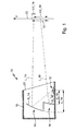
- the shows Fig. 1 a motor vehicle headlight 10 with a light source 12 and at least two optical elements 14, 16, which are arranged together with the light source 12 in the interior of a housing 18 of the piggyback 10.
- the otherwise intransparent housing 18 is covered by a transparent cover 20.
- the optical elements 14, 16 are realized in this embodiment as reflector regions R_14, R_16.
- the reflector areas R_14, R_16 are arranged by their shape and relative arrangement to the light source 12 to distribute light L_14, L_16 of the light source 12 in a predetermined manner.
- a first reflector region R_l4 is the first optical element 14 in a comparatively arranged large distance d_14 to the light source 12
- a second reflector region R_16 is arranged as a second optical element 16 in a relatively small distance d_16 to the light source 12.
- the predetermined by the shape and arrangement of the reflector areas R_14, R_16 light distribution LV, which adjusts when the light source 16 as an illuminated area on a arranged in front of the headlight 10 screen 22 is composed of a first light distribution LV_14 and a second light distribution LV_16 together.
- the first light distribution LV_14 is generated by the proportion L_14 of the light of the light source 12, which is reflected by the first optical element 14.
- the second light distribution LV_16 is generated by the proportion L_16 of the light of the light source 12, which is reflected by the second optical element 16.
- the light distribution LV_14 generated by the first optical element 14 overlaps with the light distribution LV_16 generated by the second optical element 16 to the light distribution LV, wherein the intensities of the light distributions LV_14, LV_16 add in the overlapping area.
- the second reflector region R_16 is arranged significantly closer to the light source 12 than the first reflector region R_14, the light distribution LV_16 resulting from the light L_16 of the second reflector region R_16 has a comparatively greater extent in the vertical direction V and is therefore particularly suitable for illuminating the near region in front of the vehicle and to illuminate the side apron.
- the reflector region R_16 moreover has a comparatively smaller focal length than the first reflector region R_14. He therefore collects comparatively a lot of light and therefore has a comparatively good efficiency, which increases the illumination intensity in the second light distribution LV_16. Due to the comparatively larger focal length of the first reflector region R_14, this allows, for example, a generation of a sufficiently sharp Patoscuro boundary and / or a comparatively stronger focusing of the light at a greater distance in front of the vehicle.
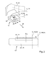
- Fig. 2 shows a perspective view of the arrangement of two reflector areas R_14, R_16 together with a light source 12, as with reference to the Fig. 1 has been explained, together with details of a preferred embodiment of the light source 12.
- the Fig. 2 a light distribution resulting from a particular operation of the light source 12.
- the shows Fig. 2 a light source 12 having a plurality of semiconductor light sources 24, 26, 28, 30.
- a plurality here is meant any natural number greater than 1.
- the semiconductor light sources 24 to 30 are mounted individually or in groups switchable on a mounting bracket 32.
- the semiconductor light sources 24 to 30 are light-emitting diodes which are controlled by a control and power electronics in the form of a control device.
- the control unit may be a component of the headlight 10 or be arranged as a separate component outside of the headlight 10 in the motor vehicle.
- the light of the semiconductor light sources 24 to 30 is preferably only through the reflector, if necessary still additionally bundled by a front lens, or by a potting of the light source with transparent plastic.
- the mounting bracket 32 may be arranged in addition to the semiconductor light sources 24 to 30 and other electronic components.
- the mounting bracket 32 may also include one or more devices for performing the heat loss occurring during operation of the semiconductor light sources to a arranged on the back of the mounting bracket heat sink.
- a mounting bracket 32 with integrated heat sink for example in the form of a metal core board, can be used.
- the mounting bracket 32 also serves to fasten the second reflector region R_16, which is arranged comparatively closer to the light source 12 than the first reflector region R_14.
- the mounting support 32 preferably serves for mounting the complete reflector component. Thereby, an accuracy of the arrangement of the semiconductor light sources 24 to 30 is achieved relative to the reflector areas R_14, R_16, which is limited only by the manufacturing accuracy of the mounting bracket 32 and the continuous reflector component.
- the illustrated light distribution LV As far as it strikes the reflector regions R_14, R_16, light emanating from the turned-on semiconductor light sources 24 to 30 is reflected by them into a main emission direction 34. This results in some distance in front of the vehicle, the illustrated light distribution LV, as they already in connection with the Fig. 1 has been explained. Unlike the Fig. 1 , which only illustrates an extension of the light distributions LV_14, LV_16 and LV in the vertical direction V, shows the Fig. 2 Also, an extension of said light distributions in the horizontal direction H. In this case, the light distribution LV_14 for the far range in the qualitative representation of Fig. 2 on the right side of the Fig. 2 bounded by a vertically extending straight line G_14 (24).
- the distance between the straight lines G_14 (24) and G_16 (24) represents a measure of the lateral range of the light distribution LV, or of the light distribution LV_16.
- the semiconductor light sources 24 to 30 are arranged in the illustrated embodiment in a transverse to the main emission direction 34 of the headlamp 10 aligned row. For this reason, the lateral range of the light distribution LV depends; or the light distribution LV_16 thereof, which of the semiconductor light sources 24 to 26 are switched on.
- the light L_14 and L_16 which generates the light distributions LV_14 and LV_16, generated only by a single switched semiconductor light source 24.
- the remaining semiconductor light sources 26, 28, 30 are switched off.
- the position of the straight lines G_14 and G_16 depends only on the first semiconductor light source 24.
- the lines G_14 and G_16 are in the Fig. 2 referred to as G_14 (24) and G_16 (24).
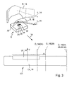
- FIG. 3 shows the subject of the Fig. 2 in a second on state and a resulting, changed light distribution, and with the lines G_14 (24) and G_16 (24) from the Fig. 2 , In the presentation of the Fig. 3 all four semiconductor light sources 24 to 30 are turned on. It can be seen that the light distribution LV_14 has only increased comparatively little beyond the position of the straight line G_14 (24) to the right due to the switching on of the further light sources 26, 28 and 30.
- the light distribution LV_16 which is generated by the reflector regions R_16 arranged closer to the light source 12, has shifted to a much greater extent beyond the position of the straight line G_16 (24) to the right and is now considered purely qualitatively by the straight line G_16 (24, 26, 28, 30) limited.
- successively switching on the semiconductor light sources 24, 26, 28, 30, a successive increase in the range of the lateral illumination is achieved in this way.
- the successive switching is effected in a preferred embodiment in dependence on a steering angle of the vehicle so that an increasing steering angle triggers an increase in the range of the lateral illumination. Due to the clear switching effect, for example, a sequential turning light can be provided in this sense.
- this switching effect also depends on the arrangement of the light sources 24-30 with respect to a central optical axis of the second reflector region 16.
- a central optical axis corresponds in one embodiment to a beam which is parallel to the main propagation direction 34 with only one semiconductor light source 24 switched on and points to the intensity maximum of the resulting second light distribution LV_16.
- the semiconductor light sources 24 to 30 are preferably arranged such that a light distribution LV_16 generated by the second optical element R_16 expands progressively to one side as the number of switched-on light sources increases.
- Such an effect results in particular for a row arrangement of the semiconductor light sources 24-30 oriented transversely to the central axis, in which the first semiconductor light source 24 lies on the central axis or lies closest to the central axis.
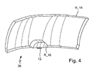
- the Fig. 4 shows an embodiment in which the reflector areas R__14 and R_16 are realized by different areas of a single reflector component 36.
- the second reflector region 16 protrudes, as it were, opposite the first reflector region in the direction of the light source 12, so that the second reflector region R_16 effectively lies between the first reflector region R_14 and the light source 12.
- the reflector regions R_14 and R_16 can also be realized by separate reflectors, that is, by separate components, as shown in the illustrations of FIGS Figures 2 and 3 suggest.
- the reflector regions R_14 and R_16 are arranged such that the second reflector region R_16, so to speak, lies between the first reflector region R_14 and the light source 12.
- the second reflector region R_16 may have different partial regions, each of which is optimized with respect to its interaction with a individually switchable semiconductor light source or individually switchable group of semiconductor light sources.
- a motor vehicle headlight 10 having the features described here can furthermore have further elements such as further optical elements, light sources and / or light modules.
Landscapes
- Engineering & Computer Science (AREA)
- General Engineering & Computer Science (AREA)
- Physics & Mathematics (AREA)
- Microelectronics & Electronic Packaging (AREA)
- Optics & Photonics (AREA)
- Non-Portable Lighting Devices Or Systems Thereof (AREA)
Abstract
Description
- Die vorliegende Erfindung betrifft einen Kraftfahrzeugscheinwerfer mit einer Lichtquelle und wenigstens zwei optischen Elementen, die dazu eingerichtet sind, Licht der Lichtquelle in vorbestimmter Weise zu verteilen.
- Ein solcher Scheinwerfer ist per se bekannt. Es sind insbesondere Kraftfahrzeugscheinwerfer mit Freiformreflektoren bekannt, deren Reflexionsfläche in einzelne Facetten oder Gruppen von Facetten unterteilt ist und bei denen verschiedene Facetten oder Gruppen von Facetten dazu eingerichtet sind, verschiedene Aufgaben bei der Erzeugung einer geforderten Gesamt-Lichtverteilung des Reflektors oder des Scheinwerfers zu erfüllen. Ein Beispiel einer solchen Aufgabe ist die Erzeugung einer ersten, eine große Reichweite aufweisenden Lichtverteilung, gegebenenfalls mit einer relativ weit vor dem Fahrzeug liegenden Hell-Dunkelgrenze. Ein anderes Beispiel ist die Erzeugung einer zweiten Lichtverteilung mit einer bestimmten Lichtintensität im seitlichen Vorfeld des Fahrzeugs, was auch als Seitenstreuung bezeichnet wird, und/oder im Nahbereich vor dem Fahrzeug.
- Die verschiedenen Facetten oder Gruppen von Facetten stellen insofern Beispiele der eingangs genannten optischen Elemente dar. Bei den bekannten Reflektoren weisen die einzelnen Teilbereiche oder Facetten jeweils etwa die gleiche Brennweite und etwa den gleichen Abstand zur Lichtquelle auf. Dabei richtet sich die Brennweite und der Abstand primär nach den Anforderungen an die erste Lichtverteilung, also an die Intensität des Lichtes bei großen Reichweiten, insbesondere in der Nähe einer Helldunkelgrenze und im Übergang vom vergleichsweise hellen Bereich unterhalb der Helldunkelgrenze zum vergleichsweise dunklen Bereich oberhalb der Helldunkelgrenze. Dazu werden vergleichsweise große Werte der Brennweite und des Abstandes zwischen der Lichtquelle und dem optischen Element verwendet.
- Die Aufgabe der Erfindung besteht in der Angabe eines Kraftfahrzeugscheinwerfers der eingangs genannten Art, der eine Verbesserung der zweiten Lichtverteilung erlaubt, ohne dafür nicht tolerierbare Nachteile bei der ersten Lichtverteilung in Kauf nehmen zu müssen.
- Diese Aufgabe wird bei einem Scheinwerfer der eingangs genannten Art durch die kennzeichnenden Merkmale des Anspruchs 1 gelöst.
- Danach ist ein erstes optisches Element in einem vergleichsweise großen Abstand zur Lichtquelle angeordnet, und ein zweites optisches Element ist in einem vergleichsweise kleinen Abstand zur Lichtquelle so angeordnet, dass sich eine vom dem ersten optischen Element erzeugte Lichtverteilung und eine vom zweiten optischen Element erzeugte Lichtverteilung überlappen.
- Durch die Anordnung des ersten optischen Elements in dem vergleichsweise großen Abstand ist eine durch das Zusammenwirken des ersten optischen Elements und der Lichtquelle erzeugte erste Lichtverteilung vergleichsweise unempfindlich gegenüber der Lichtquellengeometrie. Eine durch das Zusammenwirken des zweiten optischen Elements und der Lichtquelle erzeugte zweite Lichtverteilung ist dagegen vergleichsweise empfindlich gegenüber der Lichtquellengeometrie.
- Diese Eigenschaften erlauben eine Optimierung der zweiten Lichtverteilung, insbesondere einer Seitenstreuung, ohne dafür gravierende Nachteile bei der Optimierung der ersten Lichtverteilung in Kauf nehmen zu müssen.
- Dabei ist bevorzugt, dass das erste optische Element eine größere Brennweite besitzt als das zweite optische Element. Helldunkelgrenzen werden in der Regel mit vergleichsweise großen Brennweiten erzeugt. Diese Ausgestaltung erlaubt daher insbesondere das Beibehalten einer optimierten ersten Lichtverteilung, die eine große Reichweite aufweist und die gegebenenfalls eine Helldunkelgrenze aufweist. Die kleinere Brennweite des zweiten optischen Elements hat den Vorteil, dass sie eine konvergierende Wirkung des zweiten optischen Elements erhöht, so dass das zweite optische Element mehr Licht sammelt als es bei größerer Brennweite einsammeln würde. Dadurch wird der Wirkungsgrad des Schweinwerfers, also der Anteil des Lichtstroms, der die gewünschte Lichtverteilung erzeugt, an dem Gesamtlichtstrom der Lichtquelle, vergrößert. Diese Vergrößerung verbessert insbesondere die zweite Lichtverteilung und damit insbesondere die Seitenstreuung.
- Bevorzugt ist auch, dass die Lichtquelle eine Mehrzahl von Halbleiterlichtquellen aufweist. Diese Ausgestaltung liefert einen großen Gestaltungsspielraum beim Entwurf der Lichtquellengeometrie durch eine mögliche Variation der Anordnung und der Abstände der nur wenige mm großen einzelnen Halbleiterlichtquellen. In ihrem Zusammenwirken mit der Geometrie und Anordnung der optischen Elemente stellt die Lichtquellengeometrie eine wesentliche Einflussgröße für die Lichtverteilung des Scheinwerfers dar. In Verbindung mit den unterschiedlichen Empfindlichkeiten der beiden optischen Elemente in Bezug auf die Lichtquellengeometrie ermöglicht diese Ausgestaltung ein Design der Lichtquellengeometrie, das eine Optimierung der Seitenstreuung erlaubt, wobei gegebenenfalls auftretende Nachteile bei der Erzeugung der Helldunkelgrenze in einem tolerierbaren Rahmen gehalten werden können.
- Bevorzugt ist auch, dass die Halbleiterlichtquellen einzeln oder gruppenweise einschaltbar sind. Dadurch kann die Geometrie der Lichtquelle bei Bedarf zeitweise verändert werden, wobei ein besonderer Vorteil daraus resultiert, dass die erste Lichtverteilung vergleichsweise unempfindlich gegenüber der Lichtquellengeometrie und damit auch vergleichsweise unempfindlich gegenüber Änderungen der Lichtquellengeometrie ist, während die zweite Lichtverteilung entsprechend stärker auf die Änderungen der Lichtquellengeometrie reagiert. Dadurch wird in der Ausleuchtung des Nahbereichs vor dem Fahrzeug und des seitlichen Fahrzeugvorfeldes ein deutlicher Zuschalteffekt erzielt, ohne dass sich die langreichweitigen Anteile der Gesamtlichtverteilung in unzulässiger Weise ändern. Durch die deutlich wahrnehmbare Intensitätssteigerung im Nahbereich vor dem Fahrzeug und im seitlichen Fahrzeugvorfeld wird die Sicherheit beim Abbiegen erhöht. Durch sequenzielles Zuschalten kann dieser positive Effekt noch gesteigert werden, wobei das Zuschalten z.B. in Abhängigkeit vom Lenkwinkel erfolgt.
- Eine weitere bevorzugte Ausgestaltung sieht vor, dass die Halbleiterlichtquellen in einer quer zu einer Hauptabstrahlrichtung der Scheinwerfer ausgerichteten Reihe angeordnet sind. Die genannte Queranordnung impliziert verschiedene Abstände der einzelnen Halbleiterlichtquellen von einer zentralen, in Richtung der Hauptabstrahlrichtung des Scheinwerfers weisenden Achse, zum Beispiel einer optischen Achse, des Schweinwerfers und/oder des zweiten optischen Elements. Mit zunehmenden Abstand der eingeschalteten Halbleiterlichtquelle verbessert sich die Reichweite des in das seitliche Vorfeld gestreuten Lichtes.
- Bevorzugt ist auch, dass die einzelnen Lichtquellen der Reihe relativ zu einer zentralen Achse des zweiten optischen Elements so angeordnet sind, dass sich eine von dem zweiten optischen Element erzeugte Lichtverteilung mit zunehmender Anzahl eingeschalteter Lichtquellen zunehmend zu einer Seite ausdehnt. Eine Asymmetrie der Lichtquellenanordnung in Bezug auf die zentrale Achse führt also zu einer erwünschten Asymmetrie der Veränderung der Seitenstreuung. Dies ist dann von Vorteil, wenn zum Beispiel ein rechter (linker) Scheinwerfer zur Erzeugung eines rechten (linken) Abbiegelichtes eingerichtet ist.
- In einer bevorzugten Ausgestaltung ist das erste optische Element ein erster Reflektorbereich, und das zweite optische Element ist ein zweiter Reflektorbereich.
- Die Erfindung ist aber nicht auf eine Realisierung mit Reflektorebereichen beschränkt und kann alternativ auch mit Linsen realisiert werden, wobei das erste optische Element eine erste Linse ist und das zweite optische Element eine zweite Linse ist.
- Im Fall der Realisierung der Erfindung mit Reflektoren sieht eine bevorzugte Ausgestaltung vor, dass der zweite Reflektorbereich verschiedene Teilbereiche aufweist, von denen jeder in Bezug auf sein Zusammenwirken mit einer einzeln schaltbaren Halbleiterlichtquelle oder einzeln schaltbaren Gruppe von Halbleiterlichtquellen optimiert ist, was eine weitere Verbesserung der Seitenstreuung erlaubt.
- Die beschriebenen Ausgestaltungen von Reflektorlösungen lassen sich alternativ durch voneinander getrennte Reflektoren oder durch unterschiedliche Bereiche eines einzelnen Reflektorbauteils realisieren.
- Weitere Vorteile ergeben sich aus den abhängigen Ansprüchen, der Beschreibung und den beigefügten Figuren.
- Es versteht sich, dass die vorstehend genannten und die nachstehend noch zu erläuternden Merkmale nicht nur in der jeweils angegebenen Kombination, sondern auch in anderen Kombinationen oder in Alleinstellung verwendbar sind, ohne den Rahmen der vorliegenden Erfindung zu verlassen.
- Ausführungsbeispiele der Erfindung sind in den Zeichnungen dargestellt und werden in der nachfolgenden Beschreibung näher erläutert. Es zeigen, jeweils in schematischer Form:
- Fig. 1
- ein Ausführungsbeispiel eines erfindungsgemäßen Scheinwerfers;
- Fig. 2
- einzelne Elemente aus der
Fig. 1 mit einer Mehrzahl von Halbleiterlichtquellen in einem ersten Einschaltzustand und einer resultierenden Lichtverteilung; - Fig. 3
- den Gegenstand der
Fig. 2 in einem zweiten Einschaltzustand und einer resultierenden Lichtverteilung; und - Fig. 4
- eine perspektivische Darstellung eines Reflektors mit zwei zusammenhängenden Reflektorbereichen, für die sich unterschiedliche Abstände zu einer Lichtquelle ergeben.
- Im Einzelnen zeigt die
Fig. 1 einen Kraftfahrzeugscheinwerfer 10 mit einer Lichtquelle 12 und wenigstens zwei optischen Elementen 14, 16, die zusammen mit der Lichtquelle 12 im Inneren eines Gehäuses 18 des Schweinwerfers 10 angeordnet sind. Das ansonsten intransparente Gehäuse 18 wird durch eine transparente Abdeckscheibe 20 abgedeckt. Die optischen Elemente 14, 16 sind in dieser Ausgestaltung als Reflektorbereiche R_14, R_16 realisiert. - Die Reflektorbereiche R_14, R_16 sind durch ihre Form und relative Anordnung zur Lichtquelle 12 dazu eingerichtet, Licht L_14, L_16 der Lichtquelle 12 in vorbestimmter Weise zu verteilen. Dabei ist ein erster Reflektorbereich R_l4 als erstes optisches Element 14 in einem vergleichsweise großen Abstand d_14 zur Lichtquelle 12 angeordnet, und ein zweiter Reflektorbereich R_16 ist als zweites optisches Element 16 in einem vergleichsweise kleinen Abstand d_16 zur Lichtquelle 12 angeordnet.
- Die durch die Form und Anordnung der Reflektorbereiche R_14, R_16 vorbestimmte Lichtverteilung LV, die sich bei eingeschalteter Lichtquelle 16 als beleuchtete Fläche auf einem vor dem Scheinwerfer 10 angeordneten Schirm 22 einstellt, setzt sich aus einer ersten Lichtverteilung LV_14 und einer zweiten Lichtverteilung LV_16 zusammen. Die erste Lichtverteilung LV_14 wird vom Anteil L_14 des Lichtes der Lichtquelle 12 erzeugt, der vom ersten optischen Element 14 reflektiert wird. Analog wird die zweite Lichtverteilung LV_16 vom Anteil L_16 des Lichtes der Lichtquelle 12 erzeugt, der vom zweiten optischen Element 16 reflektiert wird. Die von dem ersten optischen Element 14 erzeugte Lichtverteilung LV_14 überlappt sich mit der vom zweiten optischen Element 16 erzeugten Lichtverteilung LV_16 zu der Lichtverteilung LV, wobei sich die Intensitäten der Lichtverteilungen LV_14, LV_16 im Überlappungsbereich addieren.
- Da der zweite Reflektorbereich R_16 deutlich näher an der Lichtquelle 12 angeordnet ist, als der erste Reflektorbereich R_14, hat die aus dem Licht L_16 des zweiten Reflektorbereiches R_16 resultierende Lichtverteilung LV_16 eine vergleichsweise größere Ausdehnung in vertikaler Richtung V und eignet sich daher insbesondere zur Ausleuchtung des Nahbereiches vor dem Fahrzeug und zur Ausleuchtung des seitlichen Vorfeldes. Der Reflektorbereich R_16 besitzt darüber hinaus eine vergleichsweise kleinere Brennweite als der erste Reflektorbereich R_14. Er sammelt daher vergleichsweise viel Licht und besitzt daher einen vergleichsweise guten Wirkungsgrad, was die Beleuchtungsintensität in der zweiten Lichtverteilung LV_16 erhöht. Durch die vergleichsweise größere Brennweite des ersten Reflektorbereichs R_14 erlaubt dieser zum Beispiel eine Erzeugung einer ausreichend scharfen Helldunkelgrenze und/oder eine vergleichsweise stärkere Bündelung des Lichtes in größerer Entfernung vor dem Fahrzeug.
-
Fig. 2 zeigt eine perspektivische Darstellung der Anordnung von zwei Reflektorbereichen R_14, R_16 zusammen mit einer Lichtquelle 12, wie sie unter Bezug auf dieFig. 1 erläutert worden ist, zusammen mit Details einer bevorzugten Ausgestaltung der Lichtquelle 12. Darüber hinaus zeigt dieFig. 2 eine Lichtverteilung, die sich aus einer bestimmten Betriebsweise der Lichtquelle 12 ergibt. - Im Einzelnen zeigt die
Fig. 2 eine Lichtquelle 12, die eine Mehrzahl von Halbleiterlichtquellen 24, 26, 28, 30 aufweist. Mit einer Mehrzahl ist hier jede natürliche Zahl größer als 1 gemeint. - Die Halbleiterlichtquellen 24 bis 30 sind einzeln oder in Gruppen schaltbar auf eine Montageträger 32 montiert. Die Halbleiterlichtquellen 24 bis 30 sind in einer bevorzugten Ausgestaltung Leuchtdioden, die von einer Ansteuer- und Leistungselektronik in Form eines Steuergeräts angesteuert werden. Das Steuergerät kann ein Bestandteil des Scheinwerfers 10 sein oder als separate Komponente außerhalb des Scheinwerfers 10 im Kraftfahrzeug angeordnet sein.
- Das Licht der Halbleiterlichtquellen 24 bis 30 wird bevorzugt nur durch den Reflektor, bei Bedarf noch zusätzlich durch eine Vorsatzlinse, beziehungsweise durch einen Verguss der Lichtquelle mit transparentem Kunststoff gebündelt.
- Auf dem Montageträger 32 können neben den Halbleiterlichtquellen 24 bis 30 auch weitere elektronische Bauteile angeordnet sein. Der Montageträger 32 kann darüber hinaus eine oder mehrere Vorrichtungen zur Durchführung der beim Betrieb der Halbleiterlichtquellen auftretenden Verlustwärme an einen auf der Rückseite des Montageträgers angeordneten Kühlkörper enthalten. Alternativ kann ein Montageträger 32 mit integriertem Kühlkörper, beispielsweise in Form einer Metallkernplatine, verwendet werden. In der dargestellten Ausgestaltung dient der Montageträger 32 darüber hinaus zur Befestigung des zweiten Reflektorbereichs R_16, der vergleichsweise näher an der Lichtquelle 12 angeordnet ist als der erste Reflektorbereich R_14.
- Bei einer Ausgestaltung, bei der die Reflektorbereiche R_14, R_16 durch unterschiedliche Bereiche eines einzelnen Reflektorbauteils realisiert werden, dient der Montageträger 32 bevorzugt zur Montage des kompletten Reflektorbauteils. Dadurch wird eine Genauigkeit der Anordnung der Halbleiterlichtquellen 24 bis 30 relativ zu den Reflektorbereichen R_14, R_16 erzielt, die nur von der Fertigungsgenauigkeit des Montageträgers 32 und des zusammenhängenden Reflektorbauteils begrenzt wird.
- Von den eingeschalteten Halbleiterlichtquellen 24 bis 30 ausgehendes Licht wird, soweit es auf die Reflektorbereiche R_14, R_16 trifft, von diesen in eine Hauptabstrahlrichtung 34 reflektiert. Dabei ergibt sich in einiger Entfernung vor dem Fahrzeug die dargestellte Lichtverteilung LV, wie sie bereits im Zusammenhang mit der
Fig. 1 erläutert worden ist. Im Unterschied zu derFig. 1 , die lediglich eine Ausdehnung der Lichtverteilungen LV_14, LV_16 und LV in vertikaler Richtung V veranschaulicht, zeigt dieFig. 2 auch eine Ausdehnung der genannten Lichtverteilungen in horizontaler Richtung H. Dabei wird die Lichtverteilung LV_14 für den Fernbereich in der qualitativen Darstellung derFig. 2 auf der rechten Seite derFig. 2 von einer vertikal verlaufenden Gerade G_14(24) begrenzt. Analog wird die Lichtverteilung LV_16 für den Nahbereich und die Seitenausleuchtung in der qualitativen Darstellung derFig. 2 durch eine weiter rechts vertikal verlaufende Gerade G_16(24) begrenzt. Der Abstand der Geraden G_14(24) und G_16(24) stellt ein Maß für die seitliche Reichweite der Lichtverteilung LV, beziehungsweise der Lichtverteilung LV_16 dar. - Die Halbleiterlichtquellen 24 bis 30 sind in der dargestellten Ausgestaltung in einer quer zu der Hauptabstrahlrichtung 34 des Scheinwerfers 10 ausgerichteten Reihe angeordnet. Aus diesem Grund hängt die seitliche Reichweite der Lichtverteilung LV; beziehungsweise der Lichtverteilung LV_16 davon ab, welche der Halbleiterlichtquellen 24 bis 26 eingeschaltet sind.
- In der Ausgestaltung, die in der
Fig. 2 dargestellt ist, wird das Licht L_14 und L_16, das die Lichtverteilungen LV_14 und LV_16 erzeugt, nur von einer einzigen eingeschalteten Halbleiterlichtquelle 24 erzeugt. Die übrigen Halbleiterlichtquellen 26, 28, 30 sind ausgeschaltet. - Aus diesem Grund ist die Lage der Geraden G_14 und G_16 nur von der ersten Halbleiterlichtquelle 24 abhängig. Aus diesem Grund sind die Geraden G_14 und G_16 in der
Fig. 2 als G_14(24) und G_16(24) bezeichnet. - Die
Figur 3 zeigt den Gegenstand derFig. 2 in einem zweiten Einschaltzustand und einer daraus resultierenden, veränderten Lichtverteilung, sowie mit den Geraden G_14(24) und G_16(24) aus derFig. 2 . In der Darstellung derFig. 3 sind alle vier Halbleiterlichtquellen 24 bis 30 eingeschaltet. Man erkennt, dass sich die Lichtverteilung LV_14 durch das Einschalten der weiteren Lichtquellen 26, 28 und 30 nur vergleichsweise wenig über die Lage der Geraden G_14(24) hinaus nach rechts vergrößert hat. Dagegen hat sich die Lichtverteilung LV_16, die durch den näher an der Lichtquelle 12 angeordneten Reflektorbereiche R_16 erzeugt wird, in einem wesentlich größeren Ausmaß über die Lage der Geraden G_16(24) hinaus nach rechts verschoben und wird nun, rein qualitativ betrachtet, durch die Gerade G_16(24, 26, 28, 30) begrenzt. - Der Abstand der Geraden G_16(24, 26, 28, 30) und G_14(24) stellt, wie auch bei der
Fig. 2 , ein Maß für die seitliche Reichweite der Lichtverteilung LV, beziehungsweise der Lichtverteilung LV_16 dar. Ein Vergleich dieses Abstandes in derFig. 4 mit dem entsprechenden Abstand in derFig. 2 stellt das Ausmaß der Ausdehnung der seitlichen Ausleuchtung dar, das durch die Erfindung erzielt wird. Dieses Ausmaß entspricht im Übrigen auch direkt dem Abstand der beiden Geraden G_16(24) und G_16(24, 26, 28, 30) aus derFig. 3 . - Für einen Schaltzustand der Lichtquelle 12 mit eingeschalteten Halbleiterlichtquellen 24 und 26 sowie für einen Schaltzustand der Lichtquelle 12 mit eingeschalteten Lichtquellen 24, 26 und 28 ergeben sich entsprechende Grenzen G_16(24, 26) und G_16(24, 26, 28), die zwischen den beiden Grenzen G_16(24) und G_16(24, 26, 28, 30) liegen.
- Durch sukzessive nacheinander erfolgendes Einschalten der Halbleiterlichtquellen 24, 26, 28, 30 wird auf diese Weise eine sukzessive erfolgende Vergrößerung der Reichweite der seitlichen Ausleuchtung erzielt. Das sukzessive Einschalten erfolgt in einer bevorzugten Ausgestaltung in Abhängigkeit von eine Lenkwinkel des Fahrzeugs so, dass ein zunehmender Lenkwinkel eine Vergrößerung der Reichweite der seitlichen Ausleuchtung auslöst. Durch den deutlichen Zuschalteffekt kann zum Beispiel ein in diesem Sinne sequentielles Abbiegelicht bereitgestellt werden.
- Die Ausprägung dieses Zuschalteffektes hängt auch von der Anordnung der Lichtquellen 24 - 30 in Bezug auf eine zentrale, optische Achse des zweiten Reflektorbereichs 16 ab. Eine solche zentrale optische Achse entspricht in einer Ausgestaltung einem Strahl, der parallel zur Hauptausbreitungsrichtung 34 bei nur einer eingeschalteten Halbleiterlichtquelle 24 liegt und zum Intensitätsmaximum der daraus resultierenden zweiten Lichtverteilung LV_16 zeigt. Relativ zu einer solchen zentralen Achse des zweiten optischen Elements R_16 sind die Halbleiterlichtquellen 24 bis 30 bevorzugt so angeordnet, dass sich eine von dem zweiten optischen Element R_16 erzeugte Lichtverteilung LV_16 mit zunehmender Anzahl eingeschalteter Lichtquellen zunehmend zu einer Seite ausdehnt. Ein solcher Effekt ergibt sich insbesondere für eine quer zur zentralen Achse ausgerichtete Reihenanordnung der Halbleiterlichtquellen 24 - 30, bei der die erste Halbleiterlichtquelle 24 auf der zentralen Achse liegt oder der zentralen Achse am nächsten liegt.
- Die
Fig. 4 zeigt eine Ausgestaltung, bei der die Reflektorbereiche R__14 und R_16 durch unterschiedliche Bereiche eines einzelnen Reflektorbauteils 36 realisiert werden. Bei dieser Ausgestaltung springt der zweite Reflektorbereich 16 gewissermaßen gegenüber dem ersten Reflektorbereich in Richtung auf die Lichtquelle 12 vor, so dass der zweite Reflektorbereich R_16 gewissermaßen zwischen dem ersten Reflektorbereich R_14 und der Lichtquelle 12 liegt. - Die Reflektorbereiche R_14 und R_16 können aber alternativ auch durch voneinander getrennte Reflektoren, also durch separate Bauteile, realisiert werden, wie es die Darstellungen der
Figuren 2 und3 nahe legen. Auch in diesem Fall sind die Reflektorbereiche R_14 und R_16 so angeordnet, dass der zweite Reflektorbereich R_16 gewissermaßen zwischen dem ersten Reflektorbereich R_14 und der Lichtquelle 12 liegt. - Unabhängig von der Ausgestaltung als separates oder mit dem ersten Reflektorbereich R_14 zusammenhängendes Bauteil ist bevorzugt, dass der zweite Reflektorbereich R_16 verschiedene Teilbereiche aufweist, von denen jeder in Bezug auf sein Zusammenwirken mit einer einzeln schaltbaren Halbleiterlichtquelle oder einzeln schaltbaren Gruppe von Halbleiterlichtquellen optimiert ist.
- Die Erfindung wurde bis zu dieser Stelle am Beispiel von Reflektorbereichen R_14, R_16 als optische Elemente 14, 16 erläutert.
- Der Fachmann erkennt jedoch, dass sich die beschriebenen Effekte auch mit Linsen als optischen Elementen 14, 16 oder mit einer Linse als optischem Element 14 und einem Reflektor als optischem Element 16, oder mit einem Reflektor als optischem Element 14 und einer Linse als optischem Element 16 erzielen lässt.
- Es versteht sich, dass ein Kraftfahrzeugscheinwerfer 10, der die hier beschriebenen Merkmale aufweist, darüber hinaus weitere Elemente wie weitere optische Elemente, Lichtquellen und/oder Lichtmodule aufweisen kann.
Claims (11)
- Kraftfahrzeugscheinwerfer (10) mit einer Lichtquelle (12) und wenigstens zwei optischen Elementen (14, 16), die dazu eingerichtet sind, Licht der Lichtquelle (12) in vorbestimmter Weise zu verteilen, dadurch gekennzeichnet, dass ein erstes optisches Element (14) in einem vergleichsweise großen Abstand (d_14) zur Lichtquelle (12) angeordnet ist und ein zweites optisches Element (16) in einem vergleichsweise kleinen Abstand (d_16) zur Lichtquelle (12) so angeordnet ist, dass sich eine vom dem ersten optischen Element (14) erzeugte Lichtverteilung (LV_14) und eine vom zweiten optischen Element (16) erzeugte Lichtverteilung (LV_16) überlappen.
- Scheinwerfer (10) nach Anspruch 1, dadurch gekennzeichnet, dass das erste optische Element (14) eine größere Brennweite besitzt als das zweite optische Element (16).
- Scheinwerfer (10) nach einem der vorhergehenden Ansprüche, dadurch gekennzeichnet, dass die Lichtquelle (12) eine Mehrzahl von Halbleiterlichtquellen (24, 26, 28, 30) aufweist.
- Scheinwerfer (10) nach einem der vorhergehenden Ansprüche, dadurch gekennzeichnet, dass die Halbleiterlichtquellen (24, 26, 28, 30) einzeln oder gruppenweise einschaltbar sind.
- Scheinwerfer (10) nach einem der vorhergehenden Ansprüche, dadurch gekennzeichnet, dass die Halbleiterlichtquellen (24, 26, 28, 30) in einer quer zu einer Hauptabstrahlrichtung (34) des Scheinwerfers (10) ausgerichteten Reihe angeordnet sind.
- Scheinwerfer (10) nach Anspruch 7, dadurch gekennzeichnet, dass die einzelnen Halbleiterlichtquellen (24, 26, 28, 30) der Reihe relativ zu einer zentralen Achse des zweiten optischen Elements (16) so angeordnet sind, dass sich eine von dem zweiten optischen Element (16) erzeugte Lichtverteilung (LV_16) mit zunehmender Anzahl eingeschalteter Halbleiterlichtquellen (24, 26, 28, 30) zunehmend zu einer Seite ausdehnt.
- Scheinwerfer (10) nach einem der vorhergehenden Ansprüche, dadurch gekennzeichnet, dass das erste optische Element (14) ein erster Reflektorbereich (R_14) ist und dass das zweite optische Element (16) ein zweiter Reflektorbereich (R_16) ist.
- Scheinwerfer (10) nach Anspruch 7, dadurch gekennzeichnet, dass der zweite Reflektorbereich (R_16) verschiedene Teilbereiche aufweist, von denen jeder in Bezug auf sein Zusammenwirken mit einer einzeln schaltbaren Halbleiterlichtquelle (24, 26, 28, 30) oder einzeln schaltbaren Gruppe von Halbleiterlichtquellen (24, 26, 28, 30) optimiert ist.
- Scheinwerfer (10) nach Anspruch 7 oder 8, dadurch gekennzeichnet, dass die Reflektorbereiche (R_14, R_16) durch voneinander getrennte Reflektoren realisiert werden.
- Scheinwerfer (10) nach Anspruch 7 oder 8, dadurch gekennzeichnet, dass die Reflektorbereiche (R_14, R_16) durch unterschiedliche Bereiche eines einzelnen Reflektorbauteils (36) realisiert werden.
- Scheinwerfer (10) nach Anspruch 2, dadurch gekennzeichnet, dass das erste optische Element (14) eine erste Linse ist und dass das zweite optische Element (16) eine zweite Linse ist.
Applications Claiming Priority (1)
| Application Number | Priority Date | Filing Date | Title |
|---|---|---|---|
| DE202010003058U DE202010003058U1 (de) | 2010-03-03 | 2010-03-03 | Kraftfahrzeugscheinwerfer mit einer Lichtquelle und wenigstens zwei Licht verteilenden optischen Elementen |
Publications (3)
| Publication Number | Publication Date |
|---|---|
| EP2366939A2 true EP2366939A2 (de) | 2011-09-21 |
| EP2366939A3 EP2366939A3 (de) | 2013-10-30 |
| EP2366939B1 EP2366939B1 (de) | 2020-06-17 |
Family
ID=42194651
Family Applications (1)
| Application Number | Title | Priority Date | Filing Date |
|---|---|---|---|
| EP11000515.4A Active EP2366939B1 (de) | 2010-03-03 | 2011-01-22 | Kraftfahrzeugscheinwerfer mit einer Lichtquelle und wenigstens zwei Licht verteilenden optischen Elementen |
Country Status (3)
| Country | Link |
|---|---|
| EP (1) | EP2366939B1 (de) |
| CN (1) | CN102192460B (de) |
| DE (1) | DE202010003058U1 (de) |
Cited By (1)
| Publication number | Priority date | Publication date | Assignee | Title |
|---|---|---|---|---|
| EP2610549A3 (de) * | 2011-12-30 | 2014-07-30 | Automotive Lighting Reutlingen GmbH | Scheinwerfer für ein Kraftfahrzeug, der eine Teilfernlicht-Lichtverteilung mit Hilfe eines Reflexionssystems erzeugt |
Families Citing this family (13)
| Publication number | Priority date | Publication date | Assignee | Title |
|---|---|---|---|---|
| JP5582865B2 (ja) * | 2010-05-12 | 2014-09-03 | 株式会社小糸製作所 | 灯具 |
| DE102010045394A1 (de) * | 2010-09-15 | 2012-03-15 | Osram Opto Semiconductors Gmbh | Leuchte |
| DE102010056311A1 (de) * | 2010-12-27 | 2012-06-28 | Automotive Lighting Reutlingen Gmbh | Beleuchtungseinrichtung eines Kraftfahrzeugs |
| JP5707661B2 (ja) * | 2011-03-25 | 2015-04-30 | スタンレー電気株式会社 | 車両用灯具ユニット及び車両用灯具に用いられる導光体 |
| JP5953665B2 (ja) * | 2011-07-26 | 2016-07-20 | 市光工業株式会社 | 車両用前照灯 |
| JP5842435B2 (ja) | 2011-07-26 | 2016-01-13 | 市光工業株式会社 | 車両用前照灯 |
| JP5912539B2 (ja) * | 2012-01-10 | 2016-04-27 | 株式会社小糸製作所 | 車両用前照灯 |
| DE102012202290B4 (de) * | 2012-02-15 | 2014-03-27 | Automotive Lighting Reutlingen Gmbh | Lichtmodul für ein blendungsfreies Kraftfahrzeug-Fernlicht |
| DE102013215359B3 (de) * | 2013-08-05 | 2015-02-19 | Automotive Lighting Reutlingen Gmbh | Mechanikfreies Kurvenlichtmodul |
| DE102013220192B4 (de) * | 2013-10-07 | 2015-04-30 | Automotive Lighting Reutlingen Gmbh | LED-Modul eines Kraftfahrzeugscheinwerfers |
| DE102014100727B4 (de) * | 2014-01-23 | 2023-09-21 | HELLA GmbH & Co. KGaA | Verfahren zur Grundeinstellung eines Scheinwerfers |
| DE102017001019A1 (de) * | 2017-02-04 | 2018-08-09 | GM Global Technology Operations LLC (n. d. Ges. d. Staates Delaware) | Fahrzeugscheinwerfer |
| CN109668111A (zh) * | 2019-02-14 | 2019-04-23 | 华域视觉科技(上海)有限公司 | 车用近光灯及包含其的汽车 |
Family Cites Families (7)
| Publication number | Priority date | Publication date | Assignee | Title |
|---|---|---|---|---|
| JP4061251B2 (ja) * | 2003-08-05 | 2008-03-12 | 株式会社小糸製作所 | 車両用灯具 |
| FR2861831B1 (fr) * | 2003-10-31 | 2006-01-20 | Valeo Vision | Module d'eclairage pour projecteur de vehicule |
| JP2008041557A (ja) * | 2006-08-09 | 2008-02-21 | Ichikoh Ind Ltd | 車両用前照灯用の灯具ユニット |
| JP4926771B2 (ja) * | 2007-03-15 | 2012-05-09 | 株式会社小糸製作所 | 車両用灯具ユニット |
| JP4864834B2 (ja) * | 2007-08-21 | 2012-02-01 | 株式会社小糸製作所 | 車両用コーナリングランプ |
| JP4979565B2 (ja) * | 2007-12-14 | 2012-07-18 | 株式会社小糸製作所 | 車両用灯具 |
| EP2322848B1 (de) * | 2009-11-12 | 2017-09-27 | Stanley Electric Co., Ltd. | Fahrzeuglicht |
-
2010
- 2010-03-03 DE DE202010003058U patent/DE202010003058U1/de not_active Expired - Lifetime
-
2011
- 2011-01-22 EP EP11000515.4A patent/EP2366939B1/de active Active
- 2011-03-03 CN CN201110059563.4A patent/CN102192460B/zh not_active Expired - Fee Related
Non-Patent Citations (1)
| Title |
|---|
| None |
Cited By (1)
| Publication number | Priority date | Publication date | Assignee | Title |
|---|---|---|---|---|
| EP2610549A3 (de) * | 2011-12-30 | 2014-07-30 | Automotive Lighting Reutlingen GmbH | Scheinwerfer für ein Kraftfahrzeug, der eine Teilfernlicht-Lichtverteilung mit Hilfe eines Reflexionssystems erzeugt |
Also Published As
| Publication number | Publication date |
|---|---|
| DE202010003058U1 (de) | 2010-05-20 |
| CN102192460A (zh) | 2011-09-21 |
| EP2366939A3 (de) | 2013-10-30 |
| EP2366939B1 (de) | 2020-06-17 |
| CN102192460B (zh) | 2015-08-05 |
Similar Documents
| Publication | Publication Date | Title |
|---|---|---|
| EP2366939B1 (de) | Kraftfahrzeugscheinwerfer mit einer Lichtquelle und wenigstens zwei Licht verteilenden optischen Elementen | |
| EP3343091B1 (de) | Lichtmodul für kraftfahrzeugscheinwerfer | |
| EP2338732B1 (de) | Kraftfahrzeugbeleuchtungseinrichtung mit einem Lichtleiter und verschiedenfarbigen Lichtquellen | |
| EP2719940B1 (de) | Lichtmodul | |
| EP2220425B1 (de) | Scheinwerfer für fahrzeuge | |
| EP3402694B1 (de) | Scheinwerfersystem und verfahren zum bereitstellen einer kurvenlichtfunktion | |
| EP2339228B1 (de) | Lichtmodul für eine Beleuchtungseinrichtung sowie Beleuchtungseinrichtung eines Kraftfahrzeugs mit einem solchen Lichtmodul | |
| AT512569B1 (de) | Beleuchtungsvorrichtung für ein Kraftfahrzeug | |
| DE102010063713A1 (de) | Beleuchtungsvorrichtung | |
| DE112019005799T5 (de) | Optisches Element einer Fahrzeugleuchte, Fahrzeugleuchtenmodul, Fahrzeug-Scheinwerfer und Fahrzeug | |
| EP2799761A2 (de) | Lichtmodul für einen Kraftfahrzeugscheinwerfer | |
| EP2363320A1 (de) | Frontscheinwerfer mit einem LED-Reflexionssystem mit Nebellicht- und Tagfahrlichtfunktion | |
| DE102014226881A1 (de) | Kraftfahrzeugscheinwerfer mit einem Zweikammerreflexionssystem | |
| EP3899358B1 (de) | Beleuchtungsvorrichtung für einen kraftfahrzeugscheinwerfer sowie kraftfahrzeugscheinwerfer | |
| EP2863108B1 (de) | LED-Modul eines Kraftfahrzeugscheinwerfers | |
| DE202017001946U1 (de) | Scheinwerfer mit einem optischen System mit statischem Matrix-Abbiegelicht | |
| EP2112978B1 (de) | Kraftfahrzeugscheinwerfer | |
| EP2284439A2 (de) | Frontscheinwerfer mit einem LED-Teilfernlichtmodul | |
| WO2011012727A1 (de) | Scheinwerfer in einem kraftfahrzeug mit einer halbleiterlichtquelle | |
| EP3812653B1 (de) | Signalleuchte mit einem lichtleiter | |
| WO2012150121A1 (de) | Strahlungsemittierende vorrichtung und verwendung einer derartigen vorrichtung | |
| DE102006029412B4 (de) | Kraftfahrzeugleuchte | |
| EP2951057B1 (de) | Fahrzeuginnenleuchte | |
| DE202021103054U1 (de) | Leuchte für Fahrzeuge und diese aufweisendes Fahrzeug | |
| EP3037717B1 (de) | Kraftfahrzeugscheinwerfer mit hohlspiegelreflektoren |
Legal Events
| Date | Code | Title | Description |
|---|---|---|---|
| PUAI | Public reference made under article 153(3) epc to a published international application that has entered the european phase |
Free format text: ORIGINAL CODE: 0009012 |
|
| AK | Designated contracting states |
Kind code of ref document: A2 Designated state(s): AL AT BE BG CH CY CZ DE DK EE ES FI FR GB GR HR HU IE IS IT LI LT LU LV MC MK MT NL NO PL PT RO RS SE SI SK SM TR |
|
| AX | Request for extension of the european patent |
Extension state: BA ME |
|
| RIN1 | Information on inventor provided before grant (corrected) |
Inventor name: SCHOLL, MICHAEL Inventor name: STADE, FLORIAN |
|
| PUAL | Search report despatched |
Free format text: ORIGINAL CODE: 0009013 |
|
| AK | Designated contracting states |
Kind code of ref document: A3 Designated state(s): AL AT BE BG CH CY CZ DE DK EE ES FI FR GB GR HR HU IE IS IT LI LT LU LV MC MK MT NL NO PL PT RO RS SE SI SK SM TR |
|
| AX | Request for extension of the european patent |
Extension state: BA ME |
|
| RIC1 | Information provided on ipc code assigned before grant |
Ipc: F21S 8/12 20060101AFI20130923BHEP Ipc: F21V 7/00 20060101ALI20130923BHEP Ipc: F21W 101/10 20060101ALN20130923BHEP Ipc: F21S 8/10 20060101ALI20130923BHEP Ipc: F21Y 101/02 20060101ALN20130923BHEP |
|
| 17P | Request for examination filed |
Effective date: 20140429 |
|
| RBV | Designated contracting states (corrected) |
Designated state(s): AL AT BE BG CH CY CZ DE DK EE ES FI FR GB GR HR HU IE IS IT LI LT LU LV MC MK MT NL NO PL PT RO RS SE SI SK SM TR |
|
| REG | Reference to a national code |
Ref country code: DE Ref legal event code: R079 Ref document number: 502011016734 Country of ref document: DE Free format text: PREVIOUS MAIN CLASS: F21S0008120000 Ipc: F21S0041147000 |
|
| RIC1 | Information provided on ipc code assigned before grant |
Ipc: F21S 41/147 20180101AFI20191119BHEP Ipc: F21S 41/663 20180101ALI20191119BHEP Ipc: F21S 41/33 20180101ALI20191119BHEP Ipc: F21S 41/36 20180101ALI20191119BHEP |
|
| GRAP | Despatch of communication of intention to grant a patent |
Free format text: ORIGINAL CODE: EPIDOSNIGR1 |
|
| STAA | Information on the status of an ep patent application or granted ep patent |
Free format text: STATUS: GRANT OF PATENT IS INTENDED |
|
| INTG | Intention to grant announced |
Effective date: 20200110 |
|
| GRAS | Grant fee paid |
Free format text: ORIGINAL CODE: EPIDOSNIGR3 |
|
| GRAA | (expected) grant |
Free format text: ORIGINAL CODE: 0009210 |
|
| STAA | Information on the status of an ep patent application or granted ep patent |
Free format text: STATUS: THE PATENT HAS BEEN GRANTED |
|
| AK | Designated contracting states |
Kind code of ref document: B1 Designated state(s): AL AT BE BG CH CY CZ DE DK EE ES FI FR GB GR HR HU IE IS IT LI LT LU LV MC MK MT NL NO PL PT RO RS SE SI SK SM TR |
|
| REG | Reference to a national code |
Ref country code: GB Ref legal event code: FG4D Free format text: NOT ENGLISH |
|
| REG | Reference to a national code |
Ref country code: CH Ref legal event code: EP |
|
| REG | Reference to a national code |
Ref country code: DE Ref legal event code: R096 Ref document number: 502011016734 Country of ref document: DE |
|
| REG | Reference to a national code |
Ref country code: IE Ref legal event code: FG4D Free format text: LANGUAGE OF EP DOCUMENT: GERMAN |
|
| REG | Reference to a national code |
Ref country code: AT Ref legal event code: REF Ref document number: 1281747 Country of ref document: AT Kind code of ref document: T Effective date: 20200715 |
|
| PG25 | Lapsed in a contracting state [announced via postgrant information from national office to epo] |
Ref country code: LT Free format text: LAPSE BECAUSE OF FAILURE TO SUBMIT A TRANSLATION OF THE DESCRIPTION OR TO PAY THE FEE WITHIN THE PRESCRIBED TIME-LIMIT Effective date: 20200617 Ref country code: NO Free format text: LAPSE BECAUSE OF FAILURE TO SUBMIT A TRANSLATION OF THE DESCRIPTION OR TO PAY THE FEE WITHIN THE PRESCRIBED TIME-LIMIT Effective date: 20200917 Ref country code: SE Free format text: LAPSE BECAUSE OF FAILURE TO SUBMIT A TRANSLATION OF THE DESCRIPTION OR TO PAY THE FEE WITHIN THE PRESCRIBED TIME-LIMIT Effective date: 20200617 Ref country code: GR Free format text: LAPSE BECAUSE OF FAILURE TO SUBMIT A TRANSLATION OF THE DESCRIPTION OR TO PAY THE FEE WITHIN THE PRESCRIBED TIME-LIMIT Effective date: 20200918 Ref country code: FI Free format text: LAPSE BECAUSE OF FAILURE TO SUBMIT A TRANSLATION OF THE DESCRIPTION OR TO PAY THE FEE WITHIN THE PRESCRIBED TIME-LIMIT Effective date: 20200617 |
|
| REG | Reference to a national code |
Ref country code: LT Ref legal event code: MG4D |
|
| REG | Reference to a national code |
Ref country code: DE Ref legal event code: R084 Ref document number: 502011016734 Country of ref document: DE |
|
| REG | Reference to a national code |
Ref country code: NL Ref legal event code: MP Effective date: 20200617 |
|
| PG25 | Lapsed in a contracting state [announced via postgrant information from national office to epo] |
Ref country code: HR Free format text: LAPSE BECAUSE OF FAILURE TO SUBMIT A TRANSLATION OF THE DESCRIPTION OR TO PAY THE FEE WITHIN THE PRESCRIBED TIME-LIMIT Effective date: 20200617 Ref country code: RS Free format text: LAPSE BECAUSE OF FAILURE TO SUBMIT A TRANSLATION OF THE DESCRIPTION OR TO PAY THE FEE WITHIN THE PRESCRIBED TIME-LIMIT Effective date: 20200617 Ref country code: LV Free format text: LAPSE BECAUSE OF FAILURE TO SUBMIT A TRANSLATION OF THE DESCRIPTION OR TO PAY THE FEE WITHIN THE PRESCRIBED TIME-LIMIT Effective date: 20200617 Ref country code: BG Free format text: LAPSE BECAUSE OF FAILURE TO SUBMIT A TRANSLATION OF THE DESCRIPTION OR TO PAY THE FEE WITHIN THE PRESCRIBED TIME-LIMIT Effective date: 20200917 |
|
| PG25 | Lapsed in a contracting state [announced via postgrant information from national office to epo] |
Ref country code: NL Free format text: LAPSE BECAUSE OF FAILURE TO SUBMIT A TRANSLATION OF THE DESCRIPTION OR TO PAY THE FEE WITHIN THE PRESCRIBED TIME-LIMIT Effective date: 20200617 Ref country code: AL Free format text: LAPSE BECAUSE OF FAILURE TO SUBMIT A TRANSLATION OF THE DESCRIPTION OR TO PAY THE FEE WITHIN THE PRESCRIBED TIME-LIMIT Effective date: 20200617 |
|
| PG25 | Lapsed in a contracting state [announced via postgrant information from national office to epo] |
Ref country code: RO Free format text: LAPSE BECAUSE OF FAILURE TO SUBMIT A TRANSLATION OF THE DESCRIPTION OR TO PAY THE FEE WITHIN THE PRESCRIBED TIME-LIMIT Effective date: 20200617 Ref country code: CZ Free format text: LAPSE BECAUSE OF FAILURE TO SUBMIT A TRANSLATION OF THE DESCRIPTION OR TO PAY THE FEE WITHIN THE PRESCRIBED TIME-LIMIT Effective date: 20200617 Ref country code: ES Free format text: LAPSE BECAUSE OF FAILURE TO SUBMIT A TRANSLATION OF THE DESCRIPTION OR TO PAY THE FEE WITHIN THE PRESCRIBED TIME-LIMIT Effective date: 20200617 Ref country code: IT Free format text: LAPSE BECAUSE OF FAILURE TO SUBMIT A TRANSLATION OF THE DESCRIPTION OR TO PAY THE FEE WITHIN THE PRESCRIBED TIME-LIMIT Effective date: 20200617 Ref country code: PT Free format text: LAPSE BECAUSE OF FAILURE TO SUBMIT A TRANSLATION OF THE DESCRIPTION OR TO PAY THE FEE WITHIN THE PRESCRIBED TIME-LIMIT Effective date: 20201019 Ref country code: SM Free format text: LAPSE BECAUSE OF FAILURE TO SUBMIT A TRANSLATION OF THE DESCRIPTION OR TO PAY THE FEE WITHIN THE PRESCRIBED TIME-LIMIT Effective date: 20200617 Ref country code: EE Free format text: LAPSE BECAUSE OF FAILURE TO SUBMIT A TRANSLATION OF THE DESCRIPTION OR TO PAY THE FEE WITHIN THE PRESCRIBED TIME-LIMIT Effective date: 20200617 |
|
| PG25 | Lapsed in a contracting state [announced via postgrant information from national office to epo] |
Ref country code: IS Free format text: LAPSE BECAUSE OF FAILURE TO SUBMIT A TRANSLATION OF THE DESCRIPTION OR TO PAY THE FEE WITHIN THE PRESCRIBED TIME-LIMIT Effective date: 20201017 Ref country code: SK Free format text: LAPSE BECAUSE OF FAILURE TO SUBMIT A TRANSLATION OF THE DESCRIPTION OR TO PAY THE FEE WITHIN THE PRESCRIBED TIME-LIMIT Effective date: 20200617 Ref country code: PL Free format text: LAPSE BECAUSE OF FAILURE TO SUBMIT A TRANSLATION OF THE DESCRIPTION OR TO PAY THE FEE WITHIN THE PRESCRIBED TIME-LIMIT Effective date: 20200617 |
|
| REG | Reference to a national code |
Ref country code: DE Ref legal event code: R026 Ref document number: 502011016734 Country of ref document: DE |
|
| PLBI | Opposition filed |
Free format text: ORIGINAL CODE: 0009260 |
|
| 26 | Opposition filed |
Opponent name: VALEO VISION Effective date: 20210317 |
|
| PG25 | Lapsed in a contracting state [announced via postgrant information from national office to epo] |
Ref country code: DK Free format text: LAPSE BECAUSE OF FAILURE TO SUBMIT A TRANSLATION OF THE DESCRIPTION OR TO PAY THE FEE WITHIN THE PRESCRIBED TIME-LIMIT Effective date: 20200617 |
|
| PG25 | Lapsed in a contracting state [announced via postgrant information from national office to epo] |
Ref country code: SI Free format text: LAPSE BECAUSE OF FAILURE TO SUBMIT A TRANSLATION OF THE DESCRIPTION OR TO PAY THE FEE WITHIN THE PRESCRIBED TIME-LIMIT Effective date: 20200617 |
|
| PLAX | Notice of opposition and request to file observation + time limit sent |
Free format text: ORIGINAL CODE: EPIDOSNOBS2 |
|
| PG25 | Lapsed in a contracting state [announced via postgrant information from national office to epo] |
Ref country code: MC Free format text: LAPSE BECAUSE OF FAILURE TO SUBMIT A TRANSLATION OF THE DESCRIPTION OR TO PAY THE FEE WITHIN THE PRESCRIBED TIME-LIMIT Effective date: 20200617 |
|
| REG | Reference to a national code |
Ref country code: CH Ref legal event code: PL |
|
| GBPC | Gb: european patent ceased through non-payment of renewal fee |
Effective date: 20210122 |
|
| PG25 | Lapsed in a contracting state [announced via postgrant information from national office to epo] |
Ref country code: LU Free format text: LAPSE BECAUSE OF NON-PAYMENT OF DUE FEES Effective date: 20210122 |
|
| REG | Reference to a national code |
Ref country code: BE Ref legal event code: MM Effective date: 20210131 |
|
| PLBB | Reply of patent proprietor to notice(s) of opposition received |
Free format text: ORIGINAL CODE: EPIDOSNOBS3 |
|
| PG25 | Lapsed in a contracting state [announced via postgrant information from national office to epo] |
Ref country code: FR Free format text: LAPSE BECAUSE OF NON-PAYMENT OF DUE FEES Effective date: 20210131 |
|
| PG25 | Lapsed in a contracting state [announced via postgrant information from national office to epo] |
Ref country code: LI Free format text: LAPSE BECAUSE OF NON-PAYMENT OF DUE FEES Effective date: 20210131 Ref country code: CH Free format text: LAPSE BECAUSE OF NON-PAYMENT OF DUE FEES Effective date: 20210131 Ref country code: GB Free format text: LAPSE BECAUSE OF NON-PAYMENT OF DUE FEES Effective date: 20210122 |
|
| PG25 | Lapsed in a contracting state [announced via postgrant information from national office to epo] |
Ref country code: IE Free format text: LAPSE BECAUSE OF NON-PAYMENT OF DUE FEES Effective date: 20210122 |
|
| REG | Reference to a national code |
Ref country code: AT Ref legal event code: MM01 Ref document number: 1281747 Country of ref document: AT Kind code of ref document: T Effective date: 20210122 |
|
| PLBP | Opposition withdrawn |
Free format text: ORIGINAL CODE: 0009264 |
|
| REG | Reference to a national code |
Ref country code: DE Ref legal event code: R100 Ref document number: 502011016734 Country of ref document: DE |
|
| PG25 | Lapsed in a contracting state [announced via postgrant information from national office to epo] |
Ref country code: AT Free format text: LAPSE BECAUSE OF NON-PAYMENT OF DUE FEES Effective date: 20210122 |
|
| PLBD | Termination of opposition procedure: decision despatched |
Free format text: ORIGINAL CODE: EPIDOSNOPC1 |
|
| PG25 | Lapsed in a contracting state [announced via postgrant information from national office to epo] |
Ref country code: IS Free format text: LAPSE BECAUSE OF FAILURE TO SUBMIT A TRANSLATION OF THE DESCRIPTION OR TO PAY THE FEE WITHIN THE PRESCRIBED TIME-LIMIT Effective date: 20201017 |
|
| PLBM | Termination of opposition procedure: date of legal effect published |
Free format text: ORIGINAL CODE: 0009276 |
|
| PG25 | Lapsed in a contracting state [announced via postgrant information from national office to epo] |
Ref country code: BE Free format text: LAPSE BECAUSE OF NON-PAYMENT OF DUE FEES Effective date: 20210131 |
|
| 27C | Opposition proceedings terminated |
Effective date: 20220416 |
|
| PG25 | Lapsed in a contracting state [announced via postgrant information from national office to epo] |
Ref country code: HU Free format text: LAPSE BECAUSE OF FAILURE TO SUBMIT A TRANSLATION OF THE DESCRIPTION OR TO PAY THE FEE WITHIN THE PRESCRIBED TIME-LIMIT; INVALID AB INITIO Effective date: 20110122 Ref country code: CY Free format text: LAPSE BECAUSE OF FAILURE TO SUBMIT A TRANSLATION OF THE DESCRIPTION OR TO PAY THE FEE WITHIN THE PRESCRIBED TIME-LIMIT Effective date: 20200617 |
|
| PG25 | Lapsed in a contracting state [announced via postgrant information from national office to epo] |
Ref country code: MK Free format text: LAPSE BECAUSE OF FAILURE TO SUBMIT A TRANSLATION OF THE DESCRIPTION OR TO PAY THE FEE WITHIN THE PRESCRIBED TIME-LIMIT Effective date: 20200617 |
|
| PG25 | Lapsed in a contracting state [announced via postgrant information from national office to epo] |
Ref country code: TR Free format text: LAPSE BECAUSE OF FAILURE TO SUBMIT A TRANSLATION OF THE DESCRIPTION OR TO PAY THE FEE WITHIN THE PRESCRIBED TIME-LIMIT Effective date: 20200617 |
|
| PG25 | Lapsed in a contracting state [announced via postgrant information from national office to epo] |
Ref country code: MT Free format text: LAPSE BECAUSE OF FAILURE TO SUBMIT A TRANSLATION OF THE DESCRIPTION OR TO PAY THE FEE WITHIN THE PRESCRIBED TIME-LIMIT Effective date: 20200617 |
|
| REG | Reference to a national code |
Ref country code: DE Ref legal event code: R081 Ref document number: 502011016734 Country of ref document: DE Owner name: MARELLI GERMANY GMBH, DE Free format text: FORMER OWNER: AUTOMOTIVE LIGHTING REUTLINGEN GMBH, 72762 REUTLINGEN, DE |
|
| PGFP | Annual fee paid to national office [announced via postgrant information from national office to epo] |
Ref country code: DE Payment date: 20251217 Year of fee payment: 16 |