EP2366580B1 - Procédé de ravitaillement et/ou de réinjection en courant indépendamment du lieu d'une unité d'accumulation et/ou de consommation mobile vers une station électrique fixe d'un fournisseur quelconque - Google Patents
Procédé de ravitaillement et/ou de réinjection en courant indépendamment du lieu d'une unité d'accumulation et/ou de consommation mobile vers une station électrique fixe d'un fournisseur quelconque Download PDFInfo
- Publication number
- EP2366580B1 EP2366580B1 EP11154183.5A EP11154183A EP2366580B1 EP 2366580 B1 EP2366580 B1 EP 2366580B1 EP 11154183 A EP11154183 A EP 11154183A EP 2366580 B1 EP2366580 B1 EP 2366580B1
- Authority
- EP
- European Patent Office
- Prior art keywords
- electricity
- charging station
- storage
- station
- consumption unit
- Prior art date
- Legal status (The legal status is an assumption and is not a legal conclusion. Google has not performed a legal analysis and makes no representation as to the accuracy of the status listed.)
- Active
Links
- 230000005611 electricity Effects 0.000 title claims description 97
- 238000000034 method Methods 0.000 title claims description 39
- 238000004891 communication Methods 0.000 claims description 67
- 230000005540 biological transmission Effects 0.000 claims description 20
- 238000013459 approach Methods 0.000 claims description 5
- 238000005516 engineering process Methods 0.000 claims description 4
- 230000001939 inductive effect Effects 0.000 claims description 4
- 238000012384 transportation and delivery Methods 0.000 claims description 4
- 230000003213 activating effect Effects 0.000 claims description 3
- 238000012545 processing Methods 0.000 claims description 3
- 230000001105 regulatory effect Effects 0.000 claims description 2
- 238000012546 transfer Methods 0.000 claims description 2
- 230000004913 activation Effects 0.000 claims 2
- 238000011161 development Methods 0.000 description 7
- 230000008901 benefit Effects 0.000 description 5
- 238000005265 energy consumption Methods 0.000 description 5
- 230000008569 process Effects 0.000 description 5
- 238000013475 authorization Methods 0.000 description 3
- 238000004590 computer program Methods 0.000 description 3
- 238000013523 data management Methods 0.000 description 3
- 238000005259 measurement Methods 0.000 description 3
- 238000011217 control strategy Methods 0.000 description 2
- 230000001276 controlling effect Effects 0.000 description 2
- 238000013461 design Methods 0.000 description 2
- 230000007246 mechanism Effects 0.000 description 2
- 102100029272 5-demethoxyubiquinone hydroxylase, mitochondrial Human genes 0.000 description 1
- 101000770593 Homo sapiens 5-demethoxyubiquinone hydroxylase, mitochondrial Proteins 0.000 description 1
- 230000008859 change Effects 0.000 description 1
- 238000012790 confirmation Methods 0.000 description 1
- 238000004146 energy storage Methods 0.000 description 1
- 230000004807 localization Effects 0.000 description 1
- 238000012423 maintenance Methods 0.000 description 1
- 230000007257 malfunction Effects 0.000 description 1
- 238000007726 management method Methods 0.000 description 1
- 238000012544 monitoring process Methods 0.000 description 1
- 230000004044 response Effects 0.000 description 1
Images
Classifications
-
- B—PERFORMING OPERATIONS; TRANSPORTING
- B60—VEHICLES IN GENERAL
- B60L—PROPULSION OF ELECTRICALLY-PROPELLED VEHICLES; SUPPLYING ELECTRIC POWER FOR AUXILIARY EQUIPMENT OF ELECTRICALLY-PROPELLED VEHICLES; ELECTRODYNAMIC BRAKE SYSTEMS FOR VEHICLES IN GENERAL; MAGNETIC SUSPENSION OR LEVITATION FOR VEHICLES; MONITORING OPERATING VARIABLES OF ELECTRICALLY-PROPELLED VEHICLES; ELECTRIC SAFETY DEVICES FOR ELECTRICALLY-PROPELLED VEHICLES
- B60L53/00—Methods of charging batteries, specially adapted for electric vehicles; Charging stations or on-board charging equipment therefor; Exchange of energy storage elements in electric vehicles
- B60L53/60—Monitoring or controlling charging stations
- B60L53/66—Data transfer between charging stations and vehicles
- B60L53/665—Methods related to measuring, billing or payment
-
- B—PERFORMING OPERATIONS; TRANSPORTING
- B60—VEHICLES IN GENERAL
- B60L—PROPULSION OF ELECTRICALLY-PROPELLED VEHICLES; SUPPLYING ELECTRIC POWER FOR AUXILIARY EQUIPMENT OF ELECTRICALLY-PROPELLED VEHICLES; ELECTRODYNAMIC BRAKE SYSTEMS FOR VEHICLES IN GENERAL; MAGNETIC SUSPENSION OR LEVITATION FOR VEHICLES; MONITORING OPERATING VARIABLES OF ELECTRICALLY-PROPELLED VEHICLES; ELECTRIC SAFETY DEVICES FOR ELECTRICALLY-PROPELLED VEHICLES
- B60L50/00—Electric propulsion with power supplied within the vehicle
- B60L50/50—Electric propulsion with power supplied within the vehicle using propulsion power supplied by batteries or fuel cells
-
- B—PERFORMING OPERATIONS; TRANSPORTING
- B60—VEHICLES IN GENERAL
- B60L—PROPULSION OF ELECTRICALLY-PROPELLED VEHICLES; SUPPLYING ELECTRIC POWER FOR AUXILIARY EQUIPMENT OF ELECTRICALLY-PROPELLED VEHICLES; ELECTRODYNAMIC BRAKE SYSTEMS FOR VEHICLES IN GENERAL; MAGNETIC SUSPENSION OR LEVITATION FOR VEHICLES; MONITORING OPERATING VARIABLES OF ELECTRICALLY-PROPELLED VEHICLES; ELECTRIC SAFETY DEVICES FOR ELECTRICALLY-PROPELLED VEHICLES
- B60L53/00—Methods of charging batteries, specially adapted for electric vehicles; Charging stations or on-board charging equipment therefor; Exchange of energy storage elements in electric vehicles
- B60L53/30—Constructional details of charging stations
- B60L53/305—Communication interfaces
-
- B—PERFORMING OPERATIONS; TRANSPORTING
- B60—VEHICLES IN GENERAL
- B60L—PROPULSION OF ELECTRICALLY-PROPELLED VEHICLES; SUPPLYING ELECTRIC POWER FOR AUXILIARY EQUIPMENT OF ELECTRICALLY-PROPELLED VEHICLES; ELECTRODYNAMIC BRAKE SYSTEMS FOR VEHICLES IN GENERAL; MAGNETIC SUSPENSION OR LEVITATION FOR VEHICLES; MONITORING OPERATING VARIABLES OF ELECTRICALLY-PROPELLED VEHICLES; ELECTRIC SAFETY DEVICES FOR ELECTRICALLY-PROPELLED VEHICLES
- B60L53/00—Methods of charging batteries, specially adapted for electric vehicles; Charging stations or on-board charging equipment therefor; Exchange of energy storage elements in electric vehicles
- B60L53/60—Monitoring or controlling charging stations
- B60L53/63—Monitoring or controlling charging stations in response to network capacity
-
- B—PERFORMING OPERATIONS; TRANSPORTING
- B60—VEHICLES IN GENERAL
- B60L—PROPULSION OF ELECTRICALLY-PROPELLED VEHICLES; SUPPLYING ELECTRIC POWER FOR AUXILIARY EQUIPMENT OF ELECTRICALLY-PROPELLED VEHICLES; ELECTRODYNAMIC BRAKE SYSTEMS FOR VEHICLES IN GENERAL; MAGNETIC SUSPENSION OR LEVITATION FOR VEHICLES; MONITORING OPERATING VARIABLES OF ELECTRICALLY-PROPELLED VEHICLES; ELECTRIC SAFETY DEVICES FOR ELECTRICALLY-PROPELLED VEHICLES
- B60L53/00—Methods of charging batteries, specially adapted for electric vehicles; Charging stations or on-board charging equipment therefor; Exchange of energy storage elements in electric vehicles
- B60L53/60—Monitoring or controlling charging stations
- B60L53/64—Optimising energy costs, e.g. responding to electricity rates
-
- B—PERFORMING OPERATIONS; TRANSPORTING
- B60—VEHICLES IN GENERAL
- B60L—PROPULSION OF ELECTRICALLY-PROPELLED VEHICLES; SUPPLYING ELECTRIC POWER FOR AUXILIARY EQUIPMENT OF ELECTRICALLY-PROPELLED VEHICLES; ELECTRODYNAMIC BRAKE SYSTEMS FOR VEHICLES IN GENERAL; MAGNETIC SUSPENSION OR LEVITATION FOR VEHICLES; MONITORING OPERATING VARIABLES OF ELECTRICALLY-PROPELLED VEHICLES; ELECTRIC SAFETY DEVICES FOR ELECTRICALLY-PROPELLED VEHICLES
- B60L53/00—Methods of charging batteries, specially adapted for electric vehicles; Charging stations or on-board charging equipment therefor; Exchange of energy storage elements in electric vehicles
- B60L53/60—Monitoring or controlling charging stations
- B60L53/65—Monitoring or controlling charging stations involving identification of vehicles or their battery types
-
- B—PERFORMING OPERATIONS; TRANSPORTING
- B60—VEHICLES IN GENERAL
- B60L—PROPULSION OF ELECTRICALLY-PROPELLED VEHICLES; SUPPLYING ELECTRIC POWER FOR AUXILIARY EQUIPMENT OF ELECTRICALLY-PROPELLED VEHICLES; ELECTRODYNAMIC BRAKE SYSTEMS FOR VEHICLES IN GENERAL; MAGNETIC SUSPENSION OR LEVITATION FOR VEHICLES; MONITORING OPERATING VARIABLES OF ELECTRICALLY-PROPELLED VEHICLES; ELECTRIC SAFETY DEVICES FOR ELECTRICALLY-PROPELLED VEHICLES
- B60L53/00—Methods of charging batteries, specially adapted for electric vehicles; Charging stations or on-board charging equipment therefor; Exchange of energy storage elements in electric vehicles
- B60L53/60—Monitoring or controlling charging stations
- B60L53/66—Data transfer between charging stations and vehicles
-
- B—PERFORMING OPERATIONS; TRANSPORTING
- B60—VEHICLES IN GENERAL
- B60L—PROPULSION OF ELECTRICALLY-PROPELLED VEHICLES; SUPPLYING ELECTRIC POWER FOR AUXILIARY EQUIPMENT OF ELECTRICALLY-PROPELLED VEHICLES; ELECTRODYNAMIC BRAKE SYSTEMS FOR VEHICLES IN GENERAL; MAGNETIC SUSPENSION OR LEVITATION FOR VEHICLES; MONITORING OPERATING VARIABLES OF ELECTRICALLY-PROPELLED VEHICLES; ELECTRIC SAFETY DEVICES FOR ELECTRICALLY-PROPELLED VEHICLES
- B60L53/00—Methods of charging batteries, specially adapted for electric vehicles; Charging stations or on-board charging equipment therefor; Exchange of energy storage elements in electric vehicles
- B60L53/60—Monitoring or controlling charging stations
- B60L53/67—Controlling two or more charging stations
-
- B—PERFORMING OPERATIONS; TRANSPORTING
- B60—VEHICLES IN GENERAL
- B60L—PROPULSION OF ELECTRICALLY-PROPELLED VEHICLES; SUPPLYING ELECTRIC POWER FOR AUXILIARY EQUIPMENT OF ELECTRICALLY-PROPELLED VEHICLES; ELECTRODYNAMIC BRAKE SYSTEMS FOR VEHICLES IN GENERAL; MAGNETIC SUSPENSION OR LEVITATION FOR VEHICLES; MONITORING OPERATING VARIABLES OF ELECTRICALLY-PROPELLED VEHICLES; ELECTRIC SAFETY DEVICES FOR ELECTRICALLY-PROPELLED VEHICLES
- B60L55/00—Arrangements for supplying energy stored within a vehicle to a power network, i.e. vehicle-to-grid [V2G] arrangements
-
- Y—GENERAL TAGGING OF NEW TECHNOLOGICAL DEVELOPMENTS; GENERAL TAGGING OF CROSS-SECTIONAL TECHNOLOGIES SPANNING OVER SEVERAL SECTIONS OF THE IPC; TECHNICAL SUBJECTS COVERED BY FORMER USPC CROSS-REFERENCE ART COLLECTIONS [XRACs] AND DIGESTS
- Y02—TECHNOLOGIES OR APPLICATIONS FOR MITIGATION OR ADAPTATION AGAINST CLIMATE CHANGE
- Y02E—REDUCTION OF GREENHOUSE GAS [GHG] EMISSIONS, RELATED TO ENERGY GENERATION, TRANSMISSION OR DISTRIBUTION
- Y02E60/00—Enabling technologies; Technologies with a potential or indirect contribution to GHG emissions mitigation
-
- Y—GENERAL TAGGING OF NEW TECHNOLOGICAL DEVELOPMENTS; GENERAL TAGGING OF CROSS-SECTIONAL TECHNOLOGIES SPANNING OVER SEVERAL SECTIONS OF THE IPC; TECHNICAL SUBJECTS COVERED BY FORMER USPC CROSS-REFERENCE ART COLLECTIONS [XRACs] AND DIGESTS
- Y02—TECHNOLOGIES OR APPLICATIONS FOR MITIGATION OR ADAPTATION AGAINST CLIMATE CHANGE
- Y02T—CLIMATE CHANGE MITIGATION TECHNOLOGIES RELATED TO TRANSPORTATION
- Y02T10/00—Road transport of goods or passengers
- Y02T10/60—Other road transportation technologies with climate change mitigation effect
- Y02T10/70—Energy storage systems for electromobility, e.g. batteries
-
- Y—GENERAL TAGGING OF NEW TECHNOLOGICAL DEVELOPMENTS; GENERAL TAGGING OF CROSS-SECTIONAL TECHNOLOGIES SPANNING OVER SEVERAL SECTIONS OF THE IPC; TECHNICAL SUBJECTS COVERED BY FORMER USPC CROSS-REFERENCE ART COLLECTIONS [XRACs] AND DIGESTS
- Y02—TECHNOLOGIES OR APPLICATIONS FOR MITIGATION OR ADAPTATION AGAINST CLIMATE CHANGE
- Y02T—CLIMATE CHANGE MITIGATION TECHNOLOGIES RELATED TO TRANSPORTATION
- Y02T10/00—Road transport of goods or passengers
- Y02T10/60—Other road transportation technologies with climate change mitigation effect
- Y02T10/7072—Electromobility specific charging systems or methods for batteries, ultracapacitors, supercapacitors or double-layer capacitors
-
- Y—GENERAL TAGGING OF NEW TECHNOLOGICAL DEVELOPMENTS; GENERAL TAGGING OF CROSS-SECTIONAL TECHNOLOGIES SPANNING OVER SEVERAL SECTIONS OF THE IPC; TECHNICAL SUBJECTS COVERED BY FORMER USPC CROSS-REFERENCE ART COLLECTIONS [XRACs] AND DIGESTS
- Y02—TECHNOLOGIES OR APPLICATIONS FOR MITIGATION OR ADAPTATION AGAINST CLIMATE CHANGE
- Y02T—CLIMATE CHANGE MITIGATION TECHNOLOGIES RELATED TO TRANSPORTATION
- Y02T90/00—Enabling technologies or technologies with a potential or indirect contribution to GHG emissions mitigation
- Y02T90/10—Technologies relating to charging of electric vehicles
- Y02T90/12—Electric charging stations
-
- Y—GENERAL TAGGING OF NEW TECHNOLOGICAL DEVELOPMENTS; GENERAL TAGGING OF CROSS-SECTIONAL TECHNOLOGIES SPANNING OVER SEVERAL SECTIONS OF THE IPC; TECHNICAL SUBJECTS COVERED BY FORMER USPC CROSS-REFERENCE ART COLLECTIONS [XRACs] AND DIGESTS
- Y02—TECHNOLOGIES OR APPLICATIONS FOR MITIGATION OR ADAPTATION AGAINST CLIMATE CHANGE
- Y02T—CLIMATE CHANGE MITIGATION TECHNOLOGIES RELATED TO TRANSPORTATION
- Y02T90/00—Enabling technologies or technologies with a potential or indirect contribution to GHG emissions mitigation
- Y02T90/10—Technologies relating to charging of electric vehicles
- Y02T90/16—Information or communication technologies improving the operation of electric vehicles
- Y02T90/167—Systems integrating technologies related to power network operation and communication or information technologies for supporting the interoperability of electric or hybrid vehicles, i.e. smartgrids as interface for battery charging of electric vehicles [EV] or hybrid vehicles [HEV]
-
- Y—GENERAL TAGGING OF NEW TECHNOLOGICAL DEVELOPMENTS; GENERAL TAGGING OF CROSS-SECTIONAL TECHNOLOGIES SPANNING OVER SEVERAL SECTIONS OF THE IPC; TECHNICAL SUBJECTS COVERED BY FORMER USPC CROSS-REFERENCE ART COLLECTIONS [XRACs] AND DIGESTS
- Y04—INFORMATION OR COMMUNICATION TECHNOLOGIES HAVING AN IMPACT ON OTHER TECHNOLOGY AREAS
- Y04S—SYSTEMS INTEGRATING TECHNOLOGIES RELATED TO POWER NETWORK OPERATION, COMMUNICATION OR INFORMATION TECHNOLOGIES FOR IMPROVING THE ELECTRICAL POWER GENERATION, TRANSMISSION, DISTRIBUTION, MANAGEMENT OR USAGE, i.e. SMART GRIDS
- Y04S10/00—Systems supporting electrical power generation, transmission or distribution
- Y04S10/12—Monitoring or controlling equipment for energy generation units, e.g. distributed energy generation [DER] or load-side generation
- Y04S10/126—Monitoring or controlling equipment for energy generation units, e.g. distributed energy generation [DER] or load-side generation the energy generation units being or involving electric vehicles [EV] or hybrid vehicles [HEV], i.e. power aggregation of EV or HEV, vehicle to grid arrangements [V2G]
-
- Y—GENERAL TAGGING OF NEW TECHNOLOGICAL DEVELOPMENTS; GENERAL TAGGING OF CROSS-SECTIONAL TECHNOLOGIES SPANNING OVER SEVERAL SECTIONS OF THE IPC; TECHNICAL SUBJECTS COVERED BY FORMER USPC CROSS-REFERENCE ART COLLECTIONS [XRACs] AND DIGESTS
- Y04—INFORMATION OR COMMUNICATION TECHNOLOGIES HAVING AN IMPACT ON OTHER TECHNOLOGY AREAS
- Y04S—SYSTEMS INTEGRATING TECHNOLOGIES RELATED TO POWER NETWORK OPERATION, COMMUNICATION OR INFORMATION TECHNOLOGIES FOR IMPROVING THE ELECTRICAL POWER GENERATION, TRANSMISSION, DISTRIBUTION, MANAGEMENT OR USAGE, i.e. SMART GRIDS
- Y04S30/00—Systems supporting specific end-user applications in the sector of transportation
- Y04S30/10—Systems supporting the interoperability of electric or hybrid vehicles
- Y04S30/14—Details associated with the interoperability, e.g. vehicle recognition, authentication, identification or billing
Definitions
- the invention relates to a method for location-independent power supply and / or for location-independent power supply of a mobile storage and consumption unit at a fixed charging station of any station operator, wherein a plurality of charging stations are supplied with power from a station supplier via power lines of at least one power distribution network operator.
- DE 41 01 053 A1 known, in which the amount of electricity purchased is paid by coins or with a check card.
- DE 295 05 733 U1 describes a charging system for electric cars with a credit card or coin operated machine. The problem arises that there are various manipulation options.
- the DE 42 13 414 C2 describes a power charging system with several electricity dispensers, each with at least one socket for connection of a charging cable and are provided with a mechanical fuse assigned to them and to which an energy metering device and a computing device which determines the electricity price are assigned, a central terminal being provided which contains the computing devices linked to the power metering devices of all the power pumps and signal lines linked to the operationally necessary components of all the power pumps is. Furthermore, an interface device assigned to each of these is connected between the terminal and each power dispenser, which contains a safety device that controls the operating state of a mechanical fuse, a safety device that responds to malfunctions, and a safety device that monitors fault currents. In this charging station, the control device contains, in particular, a magnetic card reading device for identification cards. Such a device also has to be very complex and cannot prevent misuse.
- the DE 44 14 008 C2 an arrangement for delivering electrical energy to motor vehicles with a connection to an electrical energy supply, a communication unit which has an input device for confirmation by the user and an output device for information to the user, a release circuit which, depending on the input of the user Enables energy delivery, the energy delivery only being released after a comparison of information from the input device with information that is transmitted as identification data from the motor vehicle to the release circuit.
- a card reader is used, whereby a card assigned to this contains information about the user and about the motor vehicle.
- Such a device is also equipped with at least one card reader, so that misuse when purchasing electricity cannot be ruled out.
- this known device also does not enable any real user-specific billing for customers of other electricity suppliers who want to obtain electricity from a third-party operator or who want to feed it back.
- the DE 10 2008 014 768 U1 relates to a control device for a charging station for obtaining electricity and / or for feeding a mobile storage and consumption unit.
- the control device contains at least the following components: a central control device, an actuator for actuating a switch to start and stop the charging process and / or the feeding process, a communication module for processing data from the control device for communication with the mobile memory and Consumption unit and / or with a data management system and for converting incoming signals into data that can be processed by the control unit, a measuring device for measuring the electrical energy flowing through when charging the mobile storage and consumption unit or when feeding into the charging station, an encryption module for encrypting the data from the Control unit generated data and a means connected to the measuring device for signing.
- the US 2009/0210357 A1 relates to a method for the remote-controlled consumption management of plug-in vehicles.
- Methods and systems for controlling the charging of energy storage systems in a variety of plug-in vehicles using a remote control center are provided.
- a system for controlling the charging of a plurality of remotely located plug-in vehicles is provided.
- the system includes a communication system configured to send charging permissions to charge the vehicles and receive data related to the energy consumption of each of the vehicles.
- the system also includes a controller that is coupled and configured to the communication system receive the data related to energy consumption and control the charging authorizations based on it.
- a database is also included in the system and communicates with the controller, the database being designed to store the data relating to the power consumption.
- the US 2009/0313103 A1 relates to a method, an apparatus and a computer program product for managing a charging transaction for an electric vehicle.
- specifications for the top-up transaction are identified.
- Loading information is obtained from a number of sources.
- An energy transaction plan is created from the charging information of the electric vehicle.
- a charging phase of the electric vehicle charging transaction is initiated in accordance with the energy transaction plan.
- the charging phase includes charging the electric vehicle or storing electricity in an electrical storage mechanism associated with the electric vehicle, and removing electricity from the storage mechanism to discharge the electric vehicle.
- a client's financial obligations are settled in accordance with the energy transaction plan.
- the method enables a user of the mobile storage and consumption unit to draw electrical energy from any charging station with a high level of operating convenience or to feed it into a power grid, with billing via a selected power supplier being able to take place immediately.
- a power supply or such a power supply thus offers similarly designed uses as were previously only known from fixed home connections.
- the method according to the invention additionally allows the use of a fixed charging station by a third-party operator, in which the mobile storage and / or consumption unit is not registered. It is thus possible for the first time that customers from neighboring countries can also obtain or feed in electricity from such a charging station, whereby the billing is nevertheless billed via their actual electricity provider (customer supplier).
- the roaming agreement between the station operator and a large number of customer suppliers enables a broad coverage of different customer suppliers, whose customers can use such a charging station.
- Another advantage of the method according to the invention is that the method can be carried out in the existing regulatory environment. This means that there is no need to change the power grids.
- the station supplier also operates the charging stations, and / or there is direct communication between the station supplier and the customer supplier, with a roaming agreement between the station supplier and the customer supplier.
- the charging station can be activated by the station operator. For this reason, the accounting server is assigned to a station operator.
- the transfer of the roaming data from clearing houses is realized, which is preferably additionally responsible for checking the data consistency, checking and coordinating the tariffs, assigning the storage and consumption unit to a customer supplier, activating the charging station and processing bills are.
- the first communication link between the storage and consumption unit and the charging station is established automatically. This configuration allows the user of the storage and consumption unit to be able to start buying or feeding electricity without a time delay.
- the storage and consumption unit can preferably be a vehicle with at least one electric drive.
- Such an electric vehicle is understood to mean a vehicle with at least one electric drive.
- This also includes the class of vehicles that are only additionally equipped with an electric drive, such as hybrid vehicles.
- an essential feature of an electric vehicle is the need for an electrical energy store, that is to say a battery or an accumulator.
- This accumulator can be charged regularly by connecting to an electrical supply network.
- the storage and consumption unit in the sense of the present invention can also be a device for providing electrical energy.
- the above-mentioned electric vehicles, that is to say their accumulators can also be used for feeding in electrical energy. It may also be expedient to additionally combine the electric vehicle with a device for generating electrical energy, for example with a photovoltaic system mounted on the roof of the electric vehicle.
- a charging station for a mobile storage and consumption unit is understood as a charging station.
- a charging station can be privately owned in its home network or in the possession of a third party in a location, possibly public, that is accessible to the vehicle owner.
- the stationary charging station has at least one electricity meter, it being preferred if it has two or more electricity meters.
- the storage and consumption unit also carries an electricity meter for recording the amount of electricity received by the charging station or the amount of electricity delivered to the charging station.
- This electricity meter can be used by the user of the storage and consumption unit to track the amount of energy received or the amount of energy fed in by the charging station.
- the electricity meters in the sense of this invention can be of any design, especially for the electricity meter the charging station, it only has to be ensured that the values determined by the electricity meter can also be automatically transmitted, in particular digitized, to the billing server. It is further preferred if the charging station has a further electricity meter, which records the total electricity consumption of the charging station.
- the first communication connection is wired, in particular via the charging cable using powerline communication or digital current (information transmission in the baseband near the zero crossing of the alternating current) or via a separate data cable, or via radio, in particular via WLAN, ZIGBee , Bluetooth, transponder technology or RFID.
- the second communication link between the charging station and the billing server and / or the further communication link between the billing server for the station operation and the customer billing server can be wired, preferably via DSL, ISDN, landline phone or powerline communication, digital stream or radio.
- the second communication connection can also be established directly between the storage and consumption unit and the billing server by radio.
- the second communication connection is preferably designed according to one of the two possibilities mentioned and / or the further communication connection between the billing server for the station operation and the customer billing server via radio as GSM, GPRS, UMTS, WiMAX, radio broadcasting control or paging.
- radio as GSM, GPRS, UMTS, WiMAX, radio broadcasting control or paging.
- the latter radio transmission systems have the advantage that larger ranges are also possible, if necessary.
- data about the location of the storage and consumption unit are transmitted via radio to a charging station or directly to the billing server with the aid of a location system attached to the storage and consumption unit.
- data on at least one transmission network operator are also stored on the billing server. It can also be expedient to also store data on at least one power distribution network operator and / or data on at least one customer supplier.
- the method has the particular advantage that the procurement and feeding of electricity through one or more storage and consumption units at one of the charging stations can be controlled in terms of time and / or price and / or based on control strategies for optimizing the grid stability of the electricity distribution network operator.
- transaction data are transmitted via the first, the second and / or the further communication connection.
- the transaction data can in particular be electricity prices, electricity price upper and lower limits or quantities of electricity, each of which can be assigned a specific time or period.
- the transaction data can be recorded via an input device in the vehicle, mobile or at the charging station and can be shown on a display at the charging station.
- the billing of the electricity purchased at the charging station or the corresponding power feed-in can preferably take place on the billing server or on the customer billing server using software.
- a computer program can carry out one or more of the method steps mentioned above.
- a data carrier with the computer program mentioned is also the subject of the present invention.
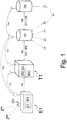
- FIG. 1 an abstract representation of the method for location-independent power supply and / or location-independent power supply.
- the mobile storage and consumption unit E1 is an electric vehicle in this exemplary embodiment.
- the stationary charging station T1 of a station operator B1 selected from a large number of charging stations T1-Tn not shown in the drawing, is connected via power lines to at least one (power) distribution network operator V1 and is supplied with electric power by a station supplier L1 via these power lines.
- a first communication connection K1 is established between the electric vehicle E1 and the charging station T1.
- This first communication connection K1 is in accordance with the illustrated embodiment Fig. 1 designed as radio link F1.
- this radio connection F1 only has to be designed for relatively short distances, WLAN, ZIGBee, Bluetooth, transponder technology or RFID are particularly suitable for this. RFID can also be used to identify the mobile storage and consumption unit E1.
- a data packet is transmitted via a second communication connection K2 to a data management system (accounting server) D1, this data packet containing at least the identification number ID1 and the counter number ID2.
- a unique identification number ID1 is assigned to the electric vehicle E1 and the charging station T1 carries an electricity meter Z2 with a meter number ID2 and a further electricity meter Z3 for recording the total electricity consumption.
- the billing server D1 can now be used to assign the electric vehicle E1 using the identification number ID1 to a customer supplier L2 and to assign the electricity meter Z2 using the meter number ID2 to a distribution network operator V1 using the data stored on the billing server D1. In this way, it can first be determined with which customer supplier L2 the electric vehicle is registered. A further data packet, containing at least the identification number ID1 and the counter number ID2, is then transmitted via a further communication connection K4 to the previously determined customer billing server D2, in which the storage and consumption unit is registered. Here, it can be checked whether the respective electric vehicle E1 has the authorization to use the station operator's station B1. After successful allocation and release of the storage and consumption unit at the customer billing server D2, the charging station T1 is activated.
- the station operator B1 In order to ensure a smooth process, there is a roaming agreement R1 between the station operator B1 and the customer supplier L2, which enables the customers of the customer supplier L2 to share the stations of the foreign station operator B1.
- the station operator B1 preferably has roaming agreements with a large number of different customer suppliers L2, which can be distributed within Germany or in different countries.
- the charging station T1 can be activated using the second communication link K2.
- the communication connections K2 and K4 can be wired, in particular via DSL, ISDN, landline telephone or powerline communication, or via radio F2, F4.
- the communication link K2 can take place directly between the electric vehicle E1 and the billing server D1 via radio F3.
- the corresponding radio connections F2, F3 and F4_ must be designed for longer distances in both exemplary embodiments, so that in particular GSM, GPRS, UMTS, WiMAX, radio ripple control or paging come into question.
- the amount of electricity withdrawn or fed in by the electric vehicle E1 at the power charging station T1 can be transmitted to the billing server D1 via the communication link K2 and to the customer billing server D2 via the communication link K4.
- the billing server D1 therefore receives, via the communication connections K2 or F2, measurement data from the electricity meter Z2 and the identification number ID1, which can be assigned directly to the respective consumption and storage unit E1 and the charging station T1.
- the billing server also stores which customer supplier L2 the electric vehicle with the ID number ID1 is assigned to and which distribution network operator V1 the meter Z2 with the meter number ID2 is assigned to.
- the customer / electric vehicle data are queried on the customer-specific billing server D2 and the charging station is activated after successful authentication and authorization. For the first time, this enables customer-specific billing of those taken from the power grid Amount of electrical energy with locally dynamic energy consumption.
- a station supplier in the sense of the invention is understood to be an energy supply company which maintains a business relationship with the station operator B1 for supplying electrical energy. This is still responsible for energy and network logistics.
- a customer supplier L2 in the sense of this invention is understood to be an energy supply company which maintains a business relationship with the owner of an electric vehicle E1 for supplying electrical energy.
- the distribution network operator V1 is assigned a separate counter. This allows the self-consumption of the charging station to be recorded separately.
- the customer supplier L2 With the help of the charging station T1 and the billing server D1, as well as the customer billing server D2, it is possible for the customer supplier L2 to bill the electric vehicle E1 for the first time, regardless of which charging station T1 visits it and regardless of whether the electric vehicle E1 visits a charging station is operated by a customer supplier L1 with whom the electric vehicle is registered, or whether the vehicle is visiting a charging station operated by a different station operator B1. Because there is a roaming agreement between the station operator B1 and the customer supplier L2, all customers of the customer supplier L2 can also use the charging stations of the station operator B1, whereby billing via the respective customer supplier L2 is still possible.
- Distribution network operator V1 is understood to mean an energy supply company whose business purpose is to set up and operate the electricity distribution network.
- the charging station T1 is located at a defined location in this distribution network.
- the distribution network operator V1 has a contractual relationship with the station supplier L1, which allows the station supplier L1 to flexibly use any charging stations T1 - Tn within the area of the distribution network operator to supply the owner of the electric vehicle E1 with electrical energy.
- a usage fee is incurred, which the station operator B1 accumulates on the basis of the electricity meter Z2 and pays the distribution network operator V1 via the station supplier L1.
- the owner of the electric vehicle E1 receives a feed-in tariff from the customer supplier L2, which the latter receives from the station operator B1.
- Transmission system operator Ü1 is understood to mean an energy supply company whose business purpose is to set up and operate the transmission network. As a further core task, which the transmission system operator Ü1 shares with the distribution system operator V1, ensuring the stability of the network is operated through a corresponding supply of balancing energy. Depending on the situation, this balancing energy can be fed into the network of the distribution network operator V1 by the electric vehicle E1 and is billed via the route electric vehicle E1 - communication link K1 - charging station T1 - second communication link K2 - billing server D1 - further communication link K4 - customer billing server D2.
- the electric vehicle E1 arrangement - first communication link K1 - charging station T1 - second communication link K2 - billing server D1 - further communication link K4 - customer billing server D2 also bills the feed-in of electrical energy from the electrical storage for the first time of an electric vehicle E1 in the network of the distribution network operator V1 or directly in the house network for own consumption.
- the electric vehicle thus forms a "virtual supply island" which relieves the public supply network of the distribution network operator V1 in times of high energy consumption.
- the method according to the invention ensures this by a differentiated measurement of the withdrawn and fed energy, with which double counting is excluded. This differentiated measurement can also be carried out by several measuring devices (submetering).
- the feed-in can be price-controlled or time-controlled or can take place on the basis of control strategies for optimizing the grid stability of the distribution network operator V1.
- the first communication link K1 between the electric vehicle E1 and the charging station T1 can be designed as desired.
- the communication link K1 can be configured to be wired.
- the communication connections K2 and K4 can also be made via a separate data cable that is used in parallel with the charging cable, for example TCP / IP via Ethernet cable CAT5 with RJ45 sockets or as a serial connection RS232, RS485 or another serial or data bus system.
- the configuration of the first communication link K1 as a radio link F1 via RFID or transponder technology would suffice, for example, to read out the identification number ID1 and, if appropriate, the counter reading of the counter Z1.
- the electric vehicle E1 makes contact with the charging station T1 via the first communication connection K1 in order to collect the meter reading from the electricity meter Z2 with the meter number ID2. Then the electric vehicle E1 sends a data record with the identification number ID1 and the meter number ID2 to the billing server D1 via the radio connection F3 and a data record to the customer billing server D2 via the radio connection F4 and obtains the release there for the purchase of electricity or for feeding of electricity. After the "refueling process", the electricity consumption values are transmitted to the billing server D1 and to the customer billing server D2 over the same route.
- the location can be supported by satellite, for example via GPS, Galileo, etc., by mobile radio via the localization within the GSM radio cell or also as car-to-car communication, in which a wide variety of electric vehicles E1 exchange information about the status of the vehicle or information, for example with regard to the next charging station T1 to Tn.
- satellite for example via GPS, Galileo, etc.
- mobile radio via the localization within the GSM radio cell or also as car-to-car communication, in which a wide variety of electric vehicles E1 exchange information about the status of the vehicle or information, for example with regard to the next charging station T1 to Tn.
Claims (12)
- Procédé d'achat d'électricité indépendamment du lieu et/ou d'alimentation en courant indépendamment du lieu d'une unité d'accumulation et de consommation mobile (E1) au niveau d'une station de recharge fixe (T1) d'un exploitant de station (B1) quelconque, dans lequel une pluralité de stations de recharge (T1 - Tn) sont alimentées en courant par des conduites de courant d'au moins un exploitant de réseau de distribution d'électricité (V1) par un fournisseur de stations (L1) et au moins les étapes suivantes sont exécutées :- établissement d'une première liaison de communication (K1) pour la transmission d'un premier paquet de données entre l'unité d'accumulation et de consommation (E1) et la station de recharge (T1) lors de l'approche physique de l'unité d'accumulation et de consommation mobile (E1) de la station de recharge fixe (T1), dans lequel, à l'unité d'accumulation et de consommation (E1) est attribué un identifiant unique (ID1) qui permet d'établir une correspondance avec un fournisseur de clients (L2) et la station de recharge (T1) comprend au moins un compteur de courant (Z2) avec un numéro de compteur (ID2) ;- transmission d'un deuxième paquet de données contenant au moins l'identifiant (ID1) et le numéro de compteur (ID2), par l'intermédiaire d'une deuxième liaison de communication (K2) entre la station de recharge et un serveur de facturation, dans lequel le serveur de facturation (D1) correspond à un exploitant de station (B1) ;- attribution de l'unité d'accumulation et de consommation (E1) à un fournisseur de clients (L2) à l'aide du premier paquet de données transmis par l'unité d'accumulation et de consommation mobile ;- transmission d'un troisième paquet de données contenant au moins l'identifiant (ID1) et le numéro de compteur (ID2) à un serveur de facturation de client (D2), dans lequel l'unité d'accumulation et de consommation est enregistrée, par l'intermédiaire d'une liaison de communication supplémentaire (K4) entre le serveur de facturation et le serveur de facturation du client (D2) ;- libération de la station de recharge (T1) après une attribution réussie et validation par le serveur de facturation de client (D2) ;- distribution de courant à l'unité d'accumulation et de consommation (E1) ou alimentation en courant de la station de recharge (T1) par l'unité d'accumulation et de consommation (E1) par l'intermédiaire d'un câble de charge ou par l'intermédiaire d'une transmission de courant sans contact, de préférence inductive ou capacitive ; et- transmission de la quantité de courant prélevée ou introduite par l'unité d'accumulation et de consommation (E1) dans la station de charge (T1) par l'intermédiaire de la deuxième liaison de communication (K2) au serveur de facturation (D1) ;dans lequel, entre l'exploitant de station (B1) et le fournisseur de client (L2), il existe un accord d'itinérance (R1) ; et
dans lequel, dans la station de recharge (T1) l'ensemble de la consommation de courant de la station de recharge (T1) est mesurée par l'intermédiaire d'un compteur de courant supplémentaire (Z3). - Procédé selon la revendication 1, caractérisé en ce que- le fournisseur de station (L1) exploite simultanément les stations de recharge T1 - Tn et/ou- une communication directe au lieu entre le fournisseur de station (L1) et le fournisseur de client (L2) et, entre le fournisseur de station (L1) et le fournisseur de client (L2), il existe un accord d'itinérance.
- Procédé selon l'une des revendications précédentes, caractérisé en ce que le transfert des données d'itinérance est réalisé par des chambres de compensation, dans lequel celles-ci prennent en charge de préférence en outre au moins une des tâches suivantes :- contrôle de la cohérence des données,- contrôle et coordination des tarifs,- attribution de l'unité d'accumulation et de consommation (E1) à un fournisseur de client (L2),- libération de la station de recharge (T1),- traitement des factures.
- Procédé selon l'une des revendications précédentes, caractérisé en ce que- lors d'une approche de l'unité d'accumulation et de consommation mobile (E1) d'une station de recharge fixe (T1), a lieu un établissement automatique de la première liaison de communication (K1) entre elles ; et/ou- l'unité d'accumulation et de consommation mobile (E1) est un véhicule avec au moins un entraînement électrique ; et/ou- l'unité d'accumulation et de consommation (E1) comprend un compteur de courant (Z1) pour la mesure de la quantité de courant prélevée de la station de recharge (T1) ou émise vers la station de recharge (T1).
- Procédé selon l'une des revendications précédentes, caractérisé en ce que- la première liaison de communication (K1) s'effectue par câble, plus particulièrement par l'intermédiaire du câble de charge ou par l'intermédiaire d'un câble de données séparé ou a lieu par radio (F1), plus particulièrement WLAN, Zigbee, Bluetooth, technologie transpondeur ou RFID ; et/ou- la deuxième liaison de communication (K2) entre la station de recharge (T1) et le serveur de facturation (D1) et/ou la liaison de communication supplémentaire (K4) s'effectuent par câble, de préférence par DSL, ISDN, téléphone fixe ou powerline ou a lieu par radio (F2) ; ou- la deuxième liaison de communication (K2) et/ou la liaison de communication supplémentaire (K4) s'effectue par radio (F2, F3, F4), de préférence GSM, GPRS, UMTS, WiMAX, radioguidage ou téléavertissement.
- Procédé selon l'une des revendications précédentes, caractérisé en ce que, à l'aide d'un système de localisation (01) monté sur l'unité d'accumulation et de consommation (E1), des données concernant le lieu de séjour sont transmises par radio à une station de recharge (T1) ou directement au serveur de facturation (D1).
- Procédé selon l'une des revendications précédentes, caractérisé en ce que, sur le serveur de facturation (D1), sont enregistrées en outre des données concernant au moins un exploitant de réseau de transmission (01) et/ou des données concernant au moins un exploitant de réseau de distribution d'électricité (V1) et/ou des données concernant au moins un fournisseur de client (L2).
- Procédé selon l'une des revendications précédentes, caractérisé en ce que l'achat de courant et l'alimentation en courant est réalisé de manière contrôlée dans le temps et/ou au niveau du prix et/ou sur la base de stratégies pour l'optimisation de la stabilité du réseau de l'exploitant de réseau de distribution d'électricité (V1), par une ou plusieurs unités d'accumulation et de consommation (E1) au niveau d'une des stations de recharge (T1 - Tn).
- Procédé selon l'une des revendications précédentes, caractérisé en ce que, par l'intermédiaire de la première et/ou de la deuxième liaison de communication et/ou de la liaison de communication supplémentaire (K1, K2, K4), des données de transactions sont transmises, qui concernent de préférence une quantité d'énergie ou une puissance demandée ou proposée par le client, dans lequel les données de transactions sont de préférence des prix de l'électricité, des limites supérieures et inférieures du prix de l'électricité ou des quantités de courant, à chacun desquels peuvent correspondre un moment ou une période déterminée.
- Procédé selon la revendication 9, caractérisé en ce que les données de transactions du client sont harmonisées avec les données de transaction correspondantes du fournisseur d'énergie et les quantités d'énergie, le temps et les puissances pour les actions d'achat d'énergie et les actions de vente d'énergie entre le client et le fournisseur d'énergie sont déterminés, dans lequel les données de transactions peuvent être saisies de préférence par l'intermédiaire d'un appareil d'entrée dans le véhicule, de manière mobile ou au niveau de la station de recharge et peuvent être affichées par l'intermédiaire d'un écran à la station de recharge.
- Station de recharge fixe (T1) pour l'achat de courant indépendamment du lieu et/ou pour l'alimentation en courant indépendamment du lieu par une unité d'accumulation et de consommation mobile (E1) au niveau de la station de recharge fixe, dans lequel la station de recharge (T1) est alimentée en courant par des conduites de courant d'au moins un exploitant de réseau de distribution d'électricité (V1) par un fournisseur de stations (L1), avec :- une première unité de communication pour l'établissement d'une première liaison de communication (K1) pour la transmission d'un premier paquet de données entre l'unité d'accumulation et de consommation (E1) et la station de recharge (T1) lors de l'approche physique de l'unité d'accumulation et de consommation mobile (E1) de la station de recharge fixe (T1), dans lequel, à l'unité d'accumulation et de consommation (E1) est attribué un identifiant unique (ID1) qui permet d'établir une correspondance avec un fournisseur de clients (L2) et la station de recharge (T1) comprend au moins un compteur de courant (Z2) avec un numéro de compteur (ID2) ;- une deuxième unité de communication pour la transmission d'un deuxième paquet de données contenant au moins l'identifiant (ID1) et le numéro de compteur (ID2), par l'intermédiaire d'une deuxième liaison de communication (K2) entre la station de recharge et un serveur de facturation, dans lequel le serveur de facturation (D1) correspond à un exploitant de station (B1) ;- une unité de libération de station de recharge pour la libération de la station de recharge (T1) après une attribution réussie et validation par le serveur de facturation de client (D2) ;- une unité de distribution pour la distribution de courant à l'unité d'accumulation et de consommation (E1) ou alimentation en courant de la station de recharge (T1) par l'unité d'accumulation et de consommation (E1) par l'intermédiaire d'un câble de charge ou par l'intermédiaire d'une transmission de courant sans contact, de préférence inductive ou capacitive ;- dans lequel la deuxième unité de communication est conçue pour la transmission de la quantité de courant prélevée ou introduite par l'unité d'accumulation et de consommation (E1) dans la station de charge (T1) par l'intermédiaire de la deuxième liaison de communication (K2) au serveur de facturation (D1) ;dans lequel, entre l'exploitant de station (B1) et le fournisseur de client (L2), il existe un accord d'itinérance (R1) ; et
dans lequel, dans la station de recharge (T1) l'ensemble de la consommation de courant de la station de recharge (T1) est mesurée par l'intermédiaire d'un compteur de courant supplémentaire (Z3). - Système pour l'achat d'électricité indépendamment du lieu et/ou d'alimentation en courant indépendamment du lieu d'une unité d'accumulation et de consommation mobile (E1) au niveau d'une station de recharge fixe (T1) d'un exploitant de station (B1) quelconque, dans lequel une pluralité de stations de recharge (T1 - Tn) sont alimentées en courant par des conduites de courant d'au moins un exploitant de réseau de distribution d'électricité (V1) par un fournisseur de stations (L1), ce système comprenant :- une station de recharge fixe selon la revendication 11 ;- un serveur de facturation (D1) qui correspond à un exploitant de station (B1), avec :i. une unité de réception pour la réception du deuxième paquet de données et de la quantité de courant prélevée ou alimentée par l'unité d'accumulation et de consommation (E1) à la station de recharge (T1) par l'intermédiaire de la deuxième liaison de communication (K2) ;ii. une unité d'attribution pour l'attribution de l'unité d'accumulation et de consommation (E1) au fournisseur de client (L2) à l'aide du premier paquet de données transmis par l'unité d'accumulation et de consommation mobile ; etiii. une unité de transmission pour la transmission d'un troisième paquet par l'intermédiaire de la liaison de communication supplémentaire (K4) ; et- un serveur de facturation de client, dans lequel l'unité d'accumulation et de consommation est enregistrée, avec une unité de communication pour la réception du troisième paquet de données provenant du serveur de facturation.
Applications Claiming Priority (1)
| Application Number | Priority Date | Filing Date | Title |
|---|---|---|---|
| DE102010009583A DE102010009583A1 (de) | 2010-02-26 | 2010-02-26 | Verfahren zum ortsunabhängigen Strombezug und/oder zur ortsunabhängigen Stromeinspeisung einer mobilen Speicher- und Verbrauchseinheit an einer ortsfesten Stromtankstelle eines beliebigen Betreibers |
Publications (3)
| Publication Number | Publication Date |
|---|---|
| EP2366580A2 EP2366580A2 (fr) | 2011-09-21 |
| EP2366580A3 EP2366580A3 (fr) | 2015-11-18 |
| EP2366580B1 true EP2366580B1 (fr) | 2020-05-27 |
Family
ID=44275666
Family Applications (1)
| Application Number | Title | Priority Date | Filing Date |
|---|---|---|---|
| EP11154183.5A Active EP2366580B1 (fr) | 2010-02-26 | 2011-02-11 | Procédé de ravitaillement et/ou de réinjection en courant indépendamment du lieu d'une unité d'accumulation et/ou de consommation mobile vers une station électrique fixe d'un fournisseur quelconque |
Country Status (2)
| Country | Link |
|---|---|
| EP (1) | EP2366580B1 (fr) |
| DE (1) | DE102010009583A1 (fr) |
Families Citing this family (12)
| Publication number | Priority date | Publication date | Assignee | Title |
|---|---|---|---|---|
| DE102011082623B3 (de) | 2011-09-13 | 2013-02-07 | Continental Automotive Gmbh | Verfahren zum Laden eines in ein Elektrokraftfahrzeug eingebauten Akkumulators |
| DE102011113354A1 (de) * | 2011-09-15 | 2013-03-21 | Rwe Ag | Verfahren und Vorrichtung zur Zuordnung eines von einer Ladestation erfassten Messwertes zu einer Transaktion |
| KR101323889B1 (ko) * | 2011-09-30 | 2013-10-30 | 엘에스산전 주식회사 | 단위 과금 방식의 전기 자동차 충전기 및 이를 포함한 전기 자동차 충전 시스템 |
| DE102012106499B4 (de) | 2012-07-18 | 2015-07-23 | Hochschule für Technik und Wirtschaft Dresden | Verfahren und System zur Authentifizierung an Ladestationen |
| KR101666697B1 (ko) * | 2012-12-20 | 2016-10-14 | 엘에스산전 주식회사 | 전기 충전 장치 및 그 제어 방법 |
| DE102013219545A1 (de) * | 2013-09-27 | 2015-04-02 | Continental Automotive Gmbh | Verfahren, Fahrzeug und Anordnung |
| DE102014214613A1 (de) * | 2014-07-25 | 2016-01-28 | Robert Bosch Gmbh | Verfahren zum Laden eines Energiespeichers eines Fahrzeugs und eine Ladestation |
| EP3564064B1 (fr) * | 2018-04-30 | 2022-11-30 | Deutsche Telekom AG | Système de station de chargement |
| CN114355870B (zh) * | 2020-09-30 | 2023-11-07 | 苏州宝时得电动工具有限公司 | 自动工作系统及方法 |
| CN112634079A (zh) * | 2020-12-22 | 2021-04-09 | 万帮数字能源股份有限公司 | 一种电能损耗计算方法 |
| DE102022103282A1 (de) | 2022-02-11 | 2023-08-17 | Westnetz Gmbh | Ladesystem und Verfahren zum Betrieb eines Ladesystems |
| EP4279327A1 (fr) * | 2022-05-17 | 2023-11-22 | Libreo GmbH | Système de charge pour charger un véhicule électrique |
Family Cites Families (11)
| Publication number | Priority date | Publication date | Assignee | Title |
|---|---|---|---|---|
| US4052655A (en) | 1975-09-10 | 1977-10-04 | Joseph Vizza | Battery recharging meter |
| DE4101053A1 (de) | 1991-01-16 | 1992-07-23 | Adrian Van Hees | Parkuhr mit elektrischem anschluss zum aufladen der batterien von kraftfahrzeugen mit antrieb durch elektromotor |
| DE4213414C2 (de) | 1992-04-23 | 1995-06-08 | Lech Elektrizitaetswerke Ag | Stromladeanlage mit mehreren Stromzapfsäulen zum Aufladen von elektrischen Energiesammlern von elektrogetriebenen Fahrzeugen mit elektrischer Energie |
| US5327066A (en) * | 1993-05-25 | 1994-07-05 | Intellectual Property Development Associates Of Connecticut, Inc. | Methods and apparatus for dispensing a consumable energy source to a vehicle |
| DE4414008C2 (de) | 1994-04-22 | 1998-03-12 | Rainer Weegen | Strom-Parkplatz |
| DE29505733U1 (de) | 1995-04-03 | 1995-08-24 | Schwarz Peter | Schnelladesystem für Elektroautos |
| US8912753B2 (en) * | 2007-10-04 | 2014-12-16 | General Motors Llc. | Remote power usage management for plug-in vehicles |
| US20090299918A1 (en) * | 2008-05-28 | 2009-12-03 | Nigelpower, Llc | Wireless delivery of power to a mobile powered device |
| US8266075B2 (en) * | 2008-06-16 | 2012-09-11 | International Business Machines Corporation | Electric vehicle charging transaction interface for managing electric vehicle charging transactions |
| DE102008044527A1 (de) | 2008-09-16 | 2010-03-25 | EnBW Energie Baden-Württemberg AG | Mobiler Stromzähler zum ortsunabhängigen Strombezug und/oder zur ortsunabhängigen Stromeinspeisung einer mobilen Speicher- und Verbrauchseinheit |
| DE202008014768U1 (de) * | 2008-09-16 | 2010-02-25 | EnBW Energie Baden-Württemberg AG | Steuervorrichtung für eine Stromtankstelle zum Strombezug und/oder zur Stromeinspeisung einer mobilen Speicher- und Verbrauchseinheit |
-
2010
- 2010-02-26 DE DE102010009583A patent/DE102010009583A1/de not_active Withdrawn
-
2011
- 2011-02-11 EP EP11154183.5A patent/EP2366580B1/fr active Active
Non-Patent Citations (1)
| Title |
|---|
| None * |
Also Published As
| Publication number | Publication date |
|---|---|
| EP2366580A2 (fr) | 2011-09-21 |
| EP2366580A3 (fr) | 2015-11-18 |
| DE102010009583A1 (de) | 2011-09-01 |
Similar Documents
| Publication | Publication Date | Title |
|---|---|---|
| EP2366580B1 (fr) | Procédé de ravitaillement et/ou de réinjection en courant indépendamment du lieu d'une unité d'accumulation et/ou de consommation mobile vers une station électrique fixe d'un fournisseur quelconque | |
| EP2326528B1 (fr) | Système de ravitaillement en courant d'une unité mobile d'accumulation et de consommation et/ou de réinjection de courant dans le réseau à partir de cette unité mobile, indépendamment du lieu | |
| EP2326529B1 (fr) | Dispositif de commande de station service électrique pour le ravitaillement en courant d'une unité mobile d'accumulation et de consommation et/ou la réinjection de courant dans le réseau à partir de cette unité mobile | |
| EP2324327B1 (fr) | Compteur de courant mobile pour le ravitaillement en courant d'une unite mobile d'accumulation et de consommation et/ou la reinjection de courant dans le reseau à partir de cette unite mobile, independamment du lieu | |
| DE102009030090B4 (de) | Verfahren, System und Vorrichtung zum Bestimmen von bezogenen Energiemengen | |
| WO2010034741A1 (fr) | Adaptateur et procédé de raccordement d'un récepteur électrique à une station de charge d'un réseau électrique | |
| DE102010018451A1 (de) | Verfahren zum Erleichtern einer Gelegenheitsaufladung eines Elektrofahrzeugs | |
| WO2014015950A2 (fr) | Procédé pour le fonctionnement d'un poste de charge | |
| WO2011039284A2 (fr) | Système et procédé pour surveiller un transfert d'énergie entre une première et une deuxième unité énergétique | |
| EP2399771B1 (fr) | Procédé de rapport indépendant du lieu d'énergie électrique d'une unité de consommation mobile sur une station service électrique fixe | |
| EP3678893A1 (fr) | Procédé de réservation d'une station de charge électrique et système de charge | |
| DE112018007800T5 (de) | Elektrofahrzeug-Energiebilanz-Gutschrift-und-Abbuchungssystem und Verfahren dazu | |
| WO2012150341A2 (fr) | Procédé pour détecter un milieu de volume déterminable et transférable d'une première unité à une deuxième unité | |
| CH713481A2 (de) | Anlage zum Errichten und Betreiben eines flächendeckenden Netzes von Batterie-Wechselstationen für elektrische Fahrzeuge. | |
| AT508853B1 (de) | Vorrichtung zum Erkennen und Autorisieren eines Stromabnehmers | |
| DE102011082623B3 (de) | Verfahren zum Laden eines in ein Elektrokraftfahrzeug eingebauten Akkumulators | |
| EP2610806A1 (fr) | Station de charge destinée à la préparation d'énergie électrique pour véhicules et procédé de fonctionnement de la station de charge | |
| EP2182607A1 (fr) | Dispositif destiné à la distribution d'énergie électrique | |
| EP4292293A1 (fr) | Procédé de transmission d'énergie électrique par l'intermédiaire d'un réseau électrique et compteur électrique | |
| DE202010004738U1 (de) | Kraftfahrzeug-Serviceeinrichtung | |
| WO2011015410A2 (fr) | Dispositif passerelle pour la détermination d'une consommation de ressources, module d'identification, système de gestion de consommation de ressources et procédé | |
| DE102019125928A1 (de) | Verfahren und Steuersystem zum Steuern einer Freischaltung einer Dienstleistungsfunktion in Abhängigkeit von einem Nutzungsverhalten eines Benutzers eines Elektrofahrzeugs | |
| CH705100A2 (de) | Batterieverleihstation zur Ausgabe, Rücknahme und Aufladung von Batterien. | |
| WO2021023359A1 (fr) | Fourniture d'énergie | |
| WO2013023889A2 (fr) | Système d'alimentation en énergie et procédé pour effectuer un transfert d'énergie |
Legal Events
| Date | Code | Title | Description |
|---|---|---|---|
| PUAI | Public reference made under article 153(3) epc to a published international application that has entered the european phase |
Free format text: ORIGINAL CODE: 0009012 |
|
| AK | Designated contracting states |
Kind code of ref document: A2 Designated state(s): AL AT BE BG CH CY CZ DE DK EE ES FI FR GB GR HR HU IE IS IT LI LT LU LV MC MK MT NL NO PL PT RO RS SE SI SK SM TR |
|
| AX | Request for extension of the european patent |
Extension state: BA ME |
|
| PUAL | Search report despatched |
Free format text: ORIGINAL CODE: 0009013 |
|
| AK | Designated contracting states |
Kind code of ref document: A3 Designated state(s): AL AT BE BG CH CY CZ DE DK EE ES FI FR GB GR HR HU IE IS IT LI LT LU LV MC MK MT NL NO PL PT RO RS SE SI SK SM TR |
|
| AX | Request for extension of the european patent |
Extension state: BA ME |
|
| RIC1 | Information provided on ipc code assigned before grant |
Ipc: B60L 11/18 20060101AFI20151012BHEP |
|
| RBV | Designated contracting states (corrected) |
Designated state(s): AL AT BE BG CH CY CZ DE DK EE ES FI FR GB GR HR HU IE IS IT LI LT LU LV MC MK MT NL NO PL PT RO RS SE SI SK SM TR |
|
| STAA | Information on the status of an ep patent application or granted ep patent |
Free format text: STATUS: REQUEST FOR EXAMINATION WAS MADE |
|
| 17P | Request for examination filed |
Effective date: 20160524 |
|
| STAA | Information on the status of an ep patent application or granted ep patent |
Free format text: STATUS: EXAMINATION IS IN PROGRESS |
|
| 17Q | First examination report despatched |
Effective date: 20180613 |
|
| REG | Reference to a national code |
Ref country code: DE Ref legal event code: R079 Ref document number: 502011016689 Country of ref document: DE Free format text: PREVIOUS MAIN CLASS: B60L0011180000 Ipc: B60L0050500000 |
|
| RIC1 | Information provided on ipc code assigned before grant |
Ipc: B60L 50/50 20190101AFI20191113BHEP |
|
| GRAP | Despatch of communication of intention to grant a patent |
Free format text: ORIGINAL CODE: EPIDOSNIGR1 |
|
| STAA | Information on the status of an ep patent application or granted ep patent |
Free format text: STATUS: GRANT OF PATENT IS INTENDED |
|
| INTG | Intention to grant announced |
Effective date: 20200130 |
|
| GRAS | Grant fee paid |
Free format text: ORIGINAL CODE: EPIDOSNIGR3 |
|
| GRAA | (expected) grant |
Free format text: ORIGINAL CODE: 0009210 |
|
| STAA | Information on the status of an ep patent application or granted ep patent |
Free format text: STATUS: THE PATENT HAS BEEN GRANTED |
|
| AK | Designated contracting states |
Kind code of ref document: B1 Designated state(s): AL AT BE BG CH CY CZ DE DK EE ES FI FR GB GR HR HU IE IS IT LI LT LU LV MC MK MT NL NO PL PT RO RS SE SI SK SM TR |
|
| REG | Reference to a national code |
Ref country code: GB Ref legal event code: FG4D Free format text: NOT ENGLISH |
|
| REG | Reference to a national code |
Ref country code: CH Ref legal event code: EP |
|
| REG | Reference to a national code |
Ref country code: DE Ref legal event code: R096 Ref document number: 502011016689 Country of ref document: DE |
|
| REG | Reference to a national code |
Ref country code: AT Ref legal event code: REF Ref document number: 1274222 Country of ref document: AT Kind code of ref document: T Effective date: 20200615 |
|
| REG | Reference to a national code |
Ref country code: CH Ref legal event code: NV Representative=s name: ISLER AND PEDRAZZINI AG, CH |
|
| REG | Reference to a national code |
Ref country code: LT Ref legal event code: MG4D |
|
| PG25 | Lapsed in a contracting state [announced via postgrant information from national office to epo] |
Ref country code: NO Free format text: LAPSE BECAUSE OF FAILURE TO SUBMIT A TRANSLATION OF THE DESCRIPTION OR TO PAY THE FEE WITHIN THE PRESCRIBED TIME-LIMIT Effective date: 20200827 Ref country code: IS Free format text: LAPSE BECAUSE OF FAILURE TO SUBMIT A TRANSLATION OF THE DESCRIPTION OR TO PAY THE FEE WITHIN THE PRESCRIBED TIME-LIMIT Effective date: 20200927 Ref country code: SE Free format text: LAPSE BECAUSE OF FAILURE TO SUBMIT A TRANSLATION OF THE DESCRIPTION OR TO PAY THE FEE WITHIN THE PRESCRIBED TIME-LIMIT Effective date: 20200527 Ref country code: LT Free format text: LAPSE BECAUSE OF FAILURE TO SUBMIT A TRANSLATION OF THE DESCRIPTION OR TO PAY THE FEE WITHIN THE PRESCRIBED TIME-LIMIT Effective date: 20200527 Ref country code: PT Free format text: LAPSE BECAUSE OF FAILURE TO SUBMIT A TRANSLATION OF THE DESCRIPTION OR TO PAY THE FEE WITHIN THE PRESCRIBED TIME-LIMIT Effective date: 20200928 Ref country code: GR Free format text: LAPSE BECAUSE OF FAILURE TO SUBMIT A TRANSLATION OF THE DESCRIPTION OR TO PAY THE FEE WITHIN THE PRESCRIBED TIME-LIMIT Effective date: 20200828 Ref country code: FI Free format text: LAPSE BECAUSE OF FAILURE TO SUBMIT A TRANSLATION OF THE DESCRIPTION OR TO PAY THE FEE WITHIN THE PRESCRIBED TIME-LIMIT Effective date: 20200527 |
|
| REG | Reference to a national code |
Ref country code: NL Ref legal event code: MP Effective date: 20200527 |
|
| PG25 | Lapsed in a contracting state [announced via postgrant information from national office to epo] |
Ref country code: LV Free format text: LAPSE BECAUSE OF FAILURE TO SUBMIT A TRANSLATION OF THE DESCRIPTION OR TO PAY THE FEE WITHIN THE PRESCRIBED TIME-LIMIT Effective date: 20200527 Ref country code: RS Free format text: LAPSE BECAUSE OF FAILURE TO SUBMIT A TRANSLATION OF THE DESCRIPTION OR TO PAY THE FEE WITHIN THE PRESCRIBED TIME-LIMIT Effective date: 20200527 Ref country code: HR Free format text: LAPSE BECAUSE OF FAILURE TO SUBMIT A TRANSLATION OF THE DESCRIPTION OR TO PAY THE FEE WITHIN THE PRESCRIBED TIME-LIMIT Effective date: 20200527 Ref country code: BG Free format text: LAPSE BECAUSE OF FAILURE TO SUBMIT A TRANSLATION OF THE DESCRIPTION OR TO PAY THE FEE WITHIN THE PRESCRIBED TIME-LIMIT Effective date: 20200827 |
|
| PG25 | Lapsed in a contracting state [announced via postgrant information from national office to epo] |
Ref country code: NL Free format text: LAPSE BECAUSE OF FAILURE TO SUBMIT A TRANSLATION OF THE DESCRIPTION OR TO PAY THE FEE WITHIN THE PRESCRIBED TIME-LIMIT Effective date: 20200527 Ref country code: AL Free format text: LAPSE BECAUSE OF FAILURE TO SUBMIT A TRANSLATION OF THE DESCRIPTION OR TO PAY THE FEE WITHIN THE PRESCRIBED TIME-LIMIT Effective date: 20200527 |
|
| PG25 | Lapsed in a contracting state [announced via postgrant information from national office to epo] |
Ref country code: DK Free format text: LAPSE BECAUSE OF FAILURE TO SUBMIT A TRANSLATION OF THE DESCRIPTION OR TO PAY THE FEE WITHIN THE PRESCRIBED TIME-LIMIT Effective date: 20200527 Ref country code: IT Free format text: LAPSE BECAUSE OF FAILURE TO SUBMIT A TRANSLATION OF THE DESCRIPTION OR TO PAY THE FEE WITHIN THE PRESCRIBED TIME-LIMIT Effective date: 20200527 Ref country code: EE Free format text: LAPSE BECAUSE OF FAILURE TO SUBMIT A TRANSLATION OF THE DESCRIPTION OR TO PAY THE FEE WITHIN THE PRESCRIBED TIME-LIMIT Effective date: 20200527 Ref country code: SM Free format text: LAPSE BECAUSE OF FAILURE TO SUBMIT A TRANSLATION OF THE DESCRIPTION OR TO PAY THE FEE WITHIN THE PRESCRIBED TIME-LIMIT Effective date: 20200527 Ref country code: RO Free format text: LAPSE BECAUSE OF FAILURE TO SUBMIT A TRANSLATION OF THE DESCRIPTION OR TO PAY THE FEE WITHIN THE PRESCRIBED TIME-LIMIT Effective date: 20200527 Ref country code: ES Free format text: LAPSE BECAUSE OF FAILURE TO SUBMIT A TRANSLATION OF THE DESCRIPTION OR TO PAY THE FEE WITHIN THE PRESCRIBED TIME-LIMIT Effective date: 20200527 |
|
| PG25 | Lapsed in a contracting state [announced via postgrant information from national office to epo] |
Ref country code: SK Free format text: LAPSE BECAUSE OF FAILURE TO SUBMIT A TRANSLATION OF THE DESCRIPTION OR TO PAY THE FEE WITHIN THE PRESCRIBED TIME-LIMIT Effective date: 20200527 Ref country code: PL Free format text: LAPSE BECAUSE OF FAILURE TO SUBMIT A TRANSLATION OF THE DESCRIPTION OR TO PAY THE FEE WITHIN THE PRESCRIBED TIME-LIMIT Effective date: 20200527 |
|
| REG | Reference to a national code |
Ref country code: DE Ref legal event code: R097 Ref document number: 502011016689 Country of ref document: DE |
|
| PLBE | No opposition filed within time limit |
Free format text: ORIGINAL CODE: 0009261 |
|
| STAA | Information on the status of an ep patent application or granted ep patent |
Free format text: STATUS: NO OPPOSITION FILED WITHIN TIME LIMIT |
|
| 26N | No opposition filed |
Effective date: 20210302 |
|
| PG25 | Lapsed in a contracting state [announced via postgrant information from national office to epo] |
Ref country code: SI Free format text: LAPSE BECAUSE OF FAILURE TO SUBMIT A TRANSLATION OF THE DESCRIPTION OR TO PAY THE FEE WITHIN THE PRESCRIBED TIME-LIMIT Effective date: 20200527 |
|
| PG25 | Lapsed in a contracting state [announced via postgrant information from national office to epo] |
Ref country code: MC Free format text: LAPSE BECAUSE OF FAILURE TO SUBMIT A TRANSLATION OF THE DESCRIPTION OR TO PAY THE FEE WITHIN THE PRESCRIBED TIME-LIMIT Effective date: 20200527 |
|
| REG | Reference to a national code |
Ref country code: BE Ref legal event code: MM Effective date: 20210228 |
|
| PG25 | Lapsed in a contracting state [announced via postgrant information from national office to epo] |
Ref country code: LU Free format text: LAPSE BECAUSE OF NON-PAYMENT OF DUE FEES Effective date: 20210211 |
|
| PG25 | Lapsed in a contracting state [announced via postgrant information from national office to epo] |
Ref country code: IE Free format text: LAPSE BECAUSE OF NON-PAYMENT OF DUE FEES Effective date: 20210211 |
|
| PG25 | Lapsed in a contracting state [announced via postgrant information from national office to epo] |
Ref country code: BE Free format text: LAPSE BECAUSE OF NON-PAYMENT OF DUE FEES Effective date: 20210228 |
|
| REG | Reference to a national code |
Ref country code: DE Ref legal event code: R081 Ref document number: 502011016689 Country of ref document: DE Owner name: ENBW MOBILITY+ AG & CO. KG, DE Free format text: FORMER OWNER: ENBW ENERGIE BADEN-WUERTTEMBERG AG, 76131 KARLSRUHE, DE |
|
| REG | Reference to a national code |
Ref country code: GB Ref legal event code: 732E Free format text: REGISTERED BETWEEN 20230216 AND 20230222 |
|
| PGFP | Annual fee paid to national office [announced via postgrant information from national office to epo] |
Ref country code: FR Payment date: 20230217 Year of fee payment: 13 Ref country code: CZ Payment date: 20230130 Year of fee payment: 13 Ref country code: CH Payment date: 20230307 Year of fee payment: 13 Ref country code: AT Payment date: 20230215 Year of fee payment: 13 |
|
| PG25 | Lapsed in a contracting state [announced via postgrant information from national office to epo] |
Ref country code: HU Free format text: LAPSE BECAUSE OF FAILURE TO SUBMIT A TRANSLATION OF THE DESCRIPTION OR TO PAY THE FEE WITHIN THE PRESCRIBED TIME-LIMIT; INVALID AB INITIO Effective date: 20110211 Ref country code: CY Free format text: LAPSE BECAUSE OF FAILURE TO SUBMIT A TRANSLATION OF THE DESCRIPTION OR TO PAY THE FEE WITHIN THE PRESCRIBED TIME-LIMIT Effective date: 20200527 |
|
| P01 | Opt-out of the competence of the unified patent court (upc) registered |
Effective date: 20230530 |
|
| REG | Reference to a national code |
Ref country code: AT Ref legal event code: PC Ref document number: 1274222 Country of ref document: AT Kind code of ref document: T Owner name: ENBW MOBILITY + AG & CO KG, DE Effective date: 20230530 |
|
| PGFP | Annual fee paid to national office [announced via postgrant information from national office to epo] |
Ref country code: AT Payment date: 20240216 Year of fee payment: 14 |
|
| PG25 | Lapsed in a contracting state [announced via postgrant information from national office to epo] |
Ref country code: MK Free format text: LAPSE BECAUSE OF FAILURE TO SUBMIT A TRANSLATION OF THE DESCRIPTION OR TO PAY THE FEE WITHIN THE PRESCRIBED TIME-LIMIT Effective date: 20200527 |
|
| PGFP | Annual fee paid to national office [announced via postgrant information from national office to epo] |
Ref country code: DE Payment date: 20240216 Year of fee payment: 14 Ref country code: CZ Payment date: 20240129 Year of fee payment: 14 Ref country code: GB Payment date: 20240222 Year of fee payment: 14 Ref country code: CH Payment date: 20240301 Year of fee payment: 14 |