EP2365141A2 - Domestic water system - Google Patents
Domestic water system Download PDFInfo
- Publication number
- EP2365141A2 EP2365141A2 EP11001956A EP11001956A EP2365141A2 EP 2365141 A2 EP2365141 A2 EP 2365141A2 EP 11001956 A EP11001956 A EP 11001956A EP 11001956 A EP11001956 A EP 11001956A EP 2365141 A2 EP2365141 A2 EP 2365141A2
- Authority
- EP
- European Patent Office
- Prior art keywords
- line
- supply line
- ring line
- ring
- drinking
- Prior art date
- Legal status (The legal status is an assumption and is not a legal conclusion. Google has not performed a legal analysis and makes no representation as to the accuracy of the status listed.)
- Granted
Links
- XLYOFNOQVPJJNP-UHFFFAOYSA-N water Substances O XLYOFNOQVPJJNP-UHFFFAOYSA-N 0.000 title claims abstract description 80
- 230000035622 drinking Effects 0.000 claims abstract description 18
- 238000000034 method Methods 0.000 claims description 6
- 238000005259 measurement Methods 0.000 claims description 4
- 238000012546 transfer Methods 0.000 claims description 4
- 238000010438 heat treatment Methods 0.000 claims description 3
- 239000003651 drinking water Substances 0.000 claims 1
- 235000020188 drinking water Nutrition 0.000 claims 1
- 230000037431 insertion Effects 0.000 abstract 1
- 238000003780 insertion Methods 0.000 abstract 1
- 238000010926 purge Methods 0.000 description 6
- 238000011144 upstream manufacturing Methods 0.000 description 6
- 230000000694 effects Effects 0.000 description 5
- 238000011010 flushing procedure Methods 0.000 description 5
- 239000012530 fluid Substances 0.000 description 4
- 238000013461 design Methods 0.000 description 3
- 238000000605 extraction Methods 0.000 description 2
- 230000035784 germination Effects 0.000 description 2
- 238000009434 installation Methods 0.000 description 2
- 230000001105 regulatory effect Effects 0.000 description 2
- 241000589248 Legionella Species 0.000 description 1
- 208000007764 Legionnaires' Disease Diseases 0.000 description 1
- 230000006978 adaptation Effects 0.000 description 1
- 238000011109 contamination Methods 0.000 description 1
- 230000001276 controlling effect Effects 0.000 description 1
- 238000001816 cooling Methods 0.000 description 1
- 239000013505 freshwater Substances 0.000 description 1
- 238000012423 maintenance Methods 0.000 description 1
- 239000002351 wastewater Substances 0.000 description 1
Images

Classifications
-
- E—FIXED CONSTRUCTIONS
- E03—WATER SUPPLY; SEWERAGE
- E03B—INSTALLATIONS OR METHODS FOR OBTAINING, COLLECTING, OR DISTRIBUTING WATER
- E03B7/00—Water main or service pipe systems
- E03B7/04—Domestic or like local pipe systems
-
- E—FIXED CONSTRUCTIONS
- E03—WATER SUPPLY; SEWERAGE
- E03B—INSTALLATIONS OR METHODS FOR OBTAINING, COLLECTING, OR DISTRIBUTING WATER
- E03B7/00—Water main or service pipe systems
- E03B7/04—Domestic or like local pipe systems
- E03B7/045—Domestic or like local pipe systems diverting initially cold water in warm water supply
-
- F—MECHANICAL ENGINEERING; LIGHTING; HEATING; WEAPONS; BLASTING
- F24—HEATING; RANGES; VENTILATING
- F24D—DOMESTIC- OR SPACE-HEATING SYSTEMS, e.g. CENTRAL HEATING SYSTEMS; DOMESTIC HOT-WATER SUPPLY SYSTEMS; ELEMENTS OR COMPONENTS THEREFOR
- F24D17/00—Domestic hot-water supply systems
- F24D17/0078—Recirculation systems
Definitions
- the present invention relates to a drinking or service water system with a transfer point from a public supply network and at least one supply line for the supply of water and at least one loop leading to at least one consumer.
- This ring line is connected to the supply line via inlet and outlet openings, wherein a cross-sectional constriction is provided in the supply line, preferably between the extraction and threading openings.
- the cross-sectional constriction is designed such that when flowing through the supply line in the loop line a flow is effected, due to the Venturi effect.
- the drinking or service water system according to the present invention may be a cold or a hot water system.
- Modern hot water systems are formed with a circulation, which ensures that hot water heated by a heater is continuously circulated in the lines leading to the consumer, so that hot water is discharged immediately at a consumer water removal and germination of the system, for example by Legionella is avoided.
- the circulation prevents the cooling of hot water in the line.
- hot water circulation systems the circulation leading away from the consumer and connecting them to the heater or a boiler of the heater with a smaller diameter than the supply line is formed.
- a generic drinking or service water system is for example from the DE 10 2006 017 807 known to the present applicant.
- several ring lines go from a supply line, which communicates with the interposition of a motor-driven valve with a purge line leading to a discharge point to the dirty water line. With this configuration, it is possible to flush a supply line to dissipate stagnant water there.
- a generic drinking or service water system should be specified, which can reliably prevent stagnation in the loop.
- a drinking or service water system of the type mentioned is proposed with the present invention, which is characterized by a provided in the loop ring line pump.
- a ring line pump leading to the supply line volume flow can be generated in the loop, which leads to a secure and inevitable exchange of the volume in the loop. Accordingly, stagnation can be avoided.
- a supply line volume flow measuring device is provided with which the volume flow in the supply line can be measured.
- the measuring signal of this supply line volume flow measuring device can be processed in a control device associated with the ring line pump.
- the ring line pump can be controlled or regulated accordingly with this preferred embodiment.
- volume flow in the supply line and the volume flow in the loop further preferred to provide a ring line volume flow measuring device with which the volume flow in the loop can be measured and their flow measurement signal in the the ring line pump associated control device is processed.
- This embodiment serves in particular the purpose to control or regulate the mutual volume flows between the ring line on the one hand and the supply line on the other hand due to the activity of the loop pump.
- the inventive drinking or The process water system may have a cross-sectional constriction between the extraction and threading, due to which a pressure difference is generated in the supply line, which leads to a forced flow through the loop at a flow in the supply line.
- the volume flow at the threading opening is divided with the present invention into a ring line volume flow and a further volume flow which is not branched off into the ring line and flows in the supply line. These two volume flows unite - if no fluid is removed from the corresponding loop via a connected consumer - in the Ausfädelömie. The flow is caused due to the ring line pump even if no fluid is removed from the system via a consumer at all.
- a ring line temperature sensor with the water temperature in the loop can be measured.
- the signal of this ring line temperature sensor can be processed in the control device associated with the ring line pump.
- the loop pump can be operated temperature controlled.
- a rule may be stored in the control device, according to which, especially at higher ambient temperatures, for example in a cold water system, a cyclical flushing of the loop takes place by actuation of the ring line pump. This ensures, for example, in hot summer months at any time that fresh water is present in the loop and germination does not occur there.
- a supply line temperature sensor is further provided by which the water temperature in the supply line can be measured and whose signal is processable in the control device associated with the ring line pump.
- This supply line temperature sensor can be provided alone or in combination with the ring line temperature sensor.
- control device is designed such that the ring line pump is controllable on the basis of the or the control device discontinued signals.
- These signals may be the signals to the volumetric flows in the supply and loop lines and / or the temperature values in these two lines.
- the information about the volume flow can be made for example by measuring a pressure difference over a given flow path, in particular via a throttle.
- a flow measuring element can also be provided in the supply or ring line.
- the system comprises a heat source for heating the water, and further comprises a circulation pump provided in the supply line which circulates water contained in the system.
- This circulation pump usually comprises a circulation pump control device, which is connected in terms of control with the control device of the ring line pump, so that the two pumps can be operated in a coordinated manner. Accordingly, the two pumps can be operated so that their effects mutually reinforce each other.
- FIG. 1 shows a schematic view of a first embodiment of a drinking and service water system with a supply line 1, which is connected to a non-illustrated transfer point for service water from a public utility network, optionally with the interposition of a device for heating the service water.
- a device for heating the service water This can be a heat exchanger of a heater.
- a boiler In a hot water network, a boiler can also be integrated in a manner known per se.
- the supply line 1 communicates with the interposition of a conventional water meter and a filter with the transfer point for cold water from the public supply network.
- a plurality of ring lines may be connected, wherein the in FIG. 1 section shown limited to the representation of a loop 2.
- This ring line 2 is connected via a connection fitting 3 to the supply line.
- the connection fitting 3 comprises a Ausfädelö réelle 3a and a threading 3b and a flow resistance arranged therebetween.
- This arrangement of threading opening 3b and Ausfädelötician 3a with flow resistance arranged therebetween is designed such that when a flow through the supply line 1 in the ring line 2 preferably a flow is effected by the Venturi effect. A flow in the supply line 1 thus leads to an exchange of standing in the ring line 2 water.
- shut-off valves 5 via which the respective ring line 2 can be separated from the supply line 1 for maintenance purposes.
- the ring line can be divided into different ring line sections. So there is a loop portion 6, which is the Ausfädelö réelle 3a downstream and leads to a remote consumer 4d.
- the flow path formed by the first ring line section 6 is the longest flow path between a consumer, a shut-off valve 5 and between the supply line 1 and the corresponding consumer 4d.
- a second and with reference numerals 7 characterized Ring effetsabterrorism connects the Einfädelö réelle 3b associated shut-off valve 5 with a nearby consumer 4a.
- This second ring line section 7 forms the shortest flow path within the ring line 2 between the shut-off valve 5 and the supply line 1 and a consumer 4a.
- Further ring line sections 8 connect the aforementioned consumers 4a and 4d to further consumers 4b, 4c.
- the first ring line section 6 is formed in the embodiment shown with a nominal diameter of DN 15.
- the other ring line sections 8 and the second ring line section 7 are formed with a nominal diameter DN 12.
- DN 12 nominal diameter of DN 12
- Both nominal diameters are suitable for conducting a sufficient volume flow of service water to the individual consumers 4a to 4d, provided that water is removed from the corresponding consumers 4a to 4d.
- connection fitting 3 is preferably a connection fitting which has means for varying the passage area in the cross-sectional constriction, as a result of which the pressure difference achievable via the cross-sectional constriction can be changed dynamically, as is the case with Applicant DE 20 2007 009 832 U1 is disclosed, the disclosure of which is hereby incorporated by reference into this application.
- the connection fitting disclosed therein will hereinafter be referred to as “dynamic connection fitting", since this allows the ratio of pressure difference to flow rate through the supply line to be changed so that even at relatively low flow rates, a relatively high pressure difference is effected, resulting in a flow through the Ring line 2 leads.
- the supply line is provided as a riser several floors of a building enforcing, whereas the in FIG. 1 shown ring line the wet cell of a residential unit or a residential unit in total pictures.
- FIG. 1 embodiment shown has in the ring line 2 adjacent to the Ausfädelö réelle 3b a ring line pump 60 which is provided between this Ausfädelö réelle 3b and the associated check valve 5.
- a measuring point M1 for measuring the volume flow in the supply line 1 and for measuring the prevailing temperature of the flowing fluid there.
- the measuring point can also proceed downstream in the supply line 1 of this connection fitting 3 (see M2).
- a circulation pump 61 is provided, with which the water in the system, which is hot water, circulates in the system.
- the measurement signals for the volume flow and the temperature measured at the measuring points M1 or M2 and MR are fed to a control which acts on the respective pumps 60 and 61, respectively.
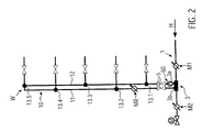
- FIG. 2 shows a schematic view of a loop 10, which is designed as a riser and two substantially parallel ring line sections comprises, which are formed as risers substantially parallel to each other and provided, for example, in a supply shaft of a building represented.
- Each of the ring line sections 11, 12 has a plurality of terminals 13 for consumers, not shown, wherein between the consumers and the respective terminals 13 close to the terminals 13 shut-off valves 14 are provided.
- the ring line 10 is also in this embodiment of a connection fitting 3 of a supply line 1 and is connected via shut-off valves 5 at the respective inlet and outlet openings 3b, 3a.
- the terminals 13 are alternately formed on the portion 11 and the portion 12 in the height direction, respectively.
- the usual main flow in the supply line is indicated by an arrow H.
- the circulation begins at the Ausfädelö réelle 3a and via the pipe sections 12, 11 leads to the threading 3b.
- the withdrawn water is almost predominantly supplied via the discharge opening 3a.
- at least the main part of the flow is supplied via the threading opening 3b.
- a measuring point M2 is shown as an alternative to the measuring point M1. Also there, temperature and / or flow rate can be measured and a central control device, which acts on the loop pump 60 and the circulation pump 61, are supplied.
- FIG. 2 embodiment shown represents a cold water system. A circulation pump is missing.
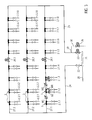
- FIG. 3 shows a further embodiment of a chilled water system with a main line 20, which opens at a distributor 21. From there go through the interposition of valves 22, 23 riser strands 24, 25 from.
- the valve 22 is a manually operated valve for shutting off the riser string 24;
- the valve 23 is a motor-operated valve for shutting off the riser string 25 and for actuating the flushing operation in conjunction with a motor-controlled flushing valve 26, whose function will be discussed later.
- each of the floor strands 27.1 to 27.3 is a motor-driven shut-off valve 28.1 to 28.3.
- the respective ring lines 2 are shown only with their associated shut-off valves 5, wherein the representation of the consumer was dispensed with these ring lines 2. It may be assumed that each of the ring lines 2 leads to a wet room in a hotel or a hospital with several cold water consumers.
- the floor strands 27.1 and 27.3 communicate with the two riser strands 24 and 25, whereby a ring line is formed, which opens into the manifold 21.
- a branch 29 which leads to a purge line 30 with a smaller nominal diameter, which can be opened and closed via the motor-driven flush valve 26 ,
- This purge line 30 opens into a sewer system.
- the respective motor-driven shut-off valves 28 are open.
- a consumer is opened on the ring main 2.1.1
- the supply of this consumer with service water takes place essentially via the riser 24.
- a consumer associated with the ring 2.1.8 open consumer the supply of hot water via the riser pipe 25.
- a consumer assigned to the central loop lines 2.1.4 or 2.1.5 is to remove water used, it flows almost equally through the riser strands 24 and 25.
- the corresponding ratio of the individual water flows changes with increasing distance from the corresponding riser strands.
- the majority of the service water is supplied via the riser pipe 24, whereas a small portion of the volume flow from the riser pipe 25 is fed.
- the measuring points M1 and M2 can optionally be provided. Also, the arrangement of the loop pump 60 and the measuring point MR can be exchanged with each other.
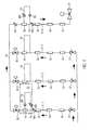
- Motor-controllable valves 36 are located at the upper end of the three left-hand strands 31.1 to 31.3. These valves 36 are provided between the individual strands 31.1 to 31.3 and the distribution line 34, whose distal end is connected to the last strand 31.4 a flow falling in the vertical direction leads and is connected at its end with a likewise controllable, ie motor-operated flushing valve 37, which leads to a discharge point.
- FIG. 4 provided ring lines 10 has a ring line pump 60.
- a measuring point MR is further provided in each individual ring line 10 in each individual ring line 10.
- one measuring point M1 for example the threading opening 3a, can be arranged upstream in the flow direction of the strand 31.
Landscapes
- Engineering & Computer Science (AREA)
- Health & Medical Sciences (AREA)
- Life Sciences & Earth Sciences (AREA)
- Hydrology & Water Resources (AREA)
- Public Health (AREA)
- Water Supply & Treatment (AREA)
- Physics & Mathematics (AREA)
- Thermal Sciences (AREA)
- Chemical & Material Sciences (AREA)
- Combustion & Propulsion (AREA)
- Mechanical Engineering (AREA)
- General Engineering & Computer Science (AREA)
- Domestic Plumbing Installations (AREA)
- Devices For Dispensing Beverages (AREA)
Abstract
Description
Die vorliegende Erfindung betrifft ein Trink- oder Brauchwassersystem mit einer Übergabestelle aus einem öffentlichen Versorgungsnetz und wenigstens einer Versorgungsleitung für die Zuleitung von Wasser und wenigstens einer Ringleitung, die zu wenigstens einem Verbraucher führt. Diese Ringleitung ist über Ein- bzw. Ausfädelöffnungen an die Versorgungsleitung angeschlossen, wobei in der Versorgungsleitung, vorzugsweise zwischen der Aus- und Einfädelöffnung eine Querschnittsverengung vorgesehen ist. Die Querschnittsverengung ist derart ausgestaltet, dass bei Durchströmung der Versorgungsleitung in der Ringleitung eine Durchströmung bewirkt wird, und zwar aufgrund des Venturi-Effekts.The present invention relates to a drinking or service water system with a transfer point from a public supply network and at least one supply line for the supply of water and at least one loop leading to at least one consumer. This ring line is connected to the supply line via inlet and outlet openings, wherein a cross-sectional constriction is provided in the supply line, preferably between the extraction and threading openings. The cross-sectional constriction is designed such that when flowing through the supply line in the loop line a flow is effected, due to the Venturi effect.
Das Trink- oder Brauchwassersystem nach der vorliegenden Erfindung kann ein Kalt- oder ein Warmwassersystem sein. Moderne Warmwassersysteme werden mit einer Zirkulation ausgebildet, die dafür Sorge trägt, dass von einer Heizvorrichtung erwärmtes Brauchwasser kontinuierlich in den zu dem Verbraucher führenden Leitungen umgewälzt wird, so dass bei einer Wasserentnahme am Verbraucher umgehend Warmwasser abgegeben wird und eine Verkeimung des Systems zum Beispiel durch Legionellen vermieden wird. Die Zirkulation verhindert ein Erkalten von in der Leitung stehendem Brauchwasser. Bei Warmwasserzirkulationssystemen ist die von dem Verbraucher wegführende und diese mit der Heizvorrichtung bzw. einem Boiler der Heizvorrichtung verbindende Zirkulationsleitung mit einem kleineren Durchmesser als die Zuführleitung ausgebildet. Der Grund hierfür liegt darin begründet, dass durch die Zuführleitung als Verbrauchsleitung ein hoher Volumenstrom bei Wasserentnahme hindurchfließen muss, wohingegen in der Zirkulationsleitung lediglich eine solche Strömung geführt werden muss, die einen ständigen Austausch des Warmwassers in den Leitungen des Warmwassersystems gewährleistet.The drinking or service water system according to the present invention may be a cold or a hot water system. Modern hot water systems are formed with a circulation, which ensures that hot water heated by a heater is continuously circulated in the lines leading to the consumer, so that hot water is discharged immediately at a consumer water removal and germination of the system, for example by Legionella is avoided. The circulation prevents the cooling of hot water in the line. In hot water circulation systems, the circulation leading away from the consumer and connecting them to the heater or a boiler of the heater with a smaller diameter than the supply line is formed. The reason for this is due to the fact that through the supply line as a consumption line, a high flow rate must flow through with water removal, whereas in the circulation line only such a flow must be performed, which ensures a constant replacement of the hot water in the lines of the hot water system.
Ein gattungsgemäßes Trink- oder Brauchwassersystem ist beispielsweise aus der
Ein weiteres System ist aus der
Die aus dem Stand der Technik bekannten Lösungen für eine Durchströmung der Ringleitung dahingehend, dass dort eine Stagnation von Trink- oder Brauchwasser vermieden wird, bedürfen der weiteren Verbesserung.The known from the prior art solutions for a flow through the loop to the effect that there stagnation of drinking or service water is avoided, require further improvement.
Mit der vorliegenden Erfindung soll ein gattungsgemäßes Trink- oder Brauchwassersystem angegeben werden, welches verlässlich eine Stagnation in der Ringleitung vermeiden kann.With the present invention, a generic drinking or service water system should be specified, which can reliably prevent stagnation in the loop.
Zur Lösung dieses Problems wird mit der vorliegenden Erfindung ein Trink- oder Brauchwassersystem der eingangs genannten Art vorgeschlagen, welches sich durch eine in der Ringleitung vorgesehene Ringleitungspumpe auszeichnet. Durch diese Ringleitungspumpe kann in der Ringleitung ein zu der Versorgungsleitung führender Volumenstrom erzeugt werden, der zu einem sicheren und zwangsläufigen Austausch des Volumens in der Ringleitung führt. Dementsprechend kann Stagnation vermieden werden.To solve this problem, a drinking or service water system of the type mentioned is proposed with the present invention, which is characterized by a provided in the loop ring line pump. Through this ring line pump leading to the supply line volume flow can be generated in the loop, which leads to a secure and inevitable exchange of the volume in the loop. Accordingly, stagnation can be avoided.
Gemäß einer weiteren bevorzugten Ausgestaltung der vorliegenden Erfindung ist eine Versorgungsleitungs-Volumenstrom-Messeinrichtung vorgesehen, mit welcher der Volumenstrom in der Versorgungsleitung messbar ist. Das Messsignal dieser Versorgungsleitungs-Volumenstrom-Messeinrichtung ist in einer der Ringleitungspumpe zugeordneten Steuereinrichtung verarbeitbar. Durch Analyse der Strömungsbedingungen in der Versorgungsleitung kann mit dieser bevorzugten Ausgestaltung die Ringleitungspumpe entsprechend gesteuert bzw. geregelt werden.According to a further preferred embodiment of the present invention, a supply line volume flow measuring device is provided with which the volume flow in the supply line can be measured. The measuring signal of this supply line volume flow measuring device can be processed in a control device associated with the ring line pump. By analyzing the flow conditions in the supply line, the ring line pump can be controlled or regulated accordingly with this preferred embodiment.
Dabei ist es im Hinblick auf eine gute Anpassung zwischen dem Volumenstrom in der Versorgungsleitung und dem Volumenstrom in der Ringleitung des Weiteren zu bevorzugen, eine Ringleitungs-Volumenstrom-Messeinrichtung vorzusehen, mit welcher der Volumenstrom in der Ringleitung messbar ist und deren Volumenstrom-Messsignal in der der Ringleitungspumpe zugeordneten Steuereinrichtung verarbeitbar ist. Diese Ausgestaltung dient dabei insbesondere dem Zweck, die beiderseitigen Volumenströme zwischen Ringleitung einerseits und Versorgungsleitung andererseits aufgrund der Aktivität der Ringleitungspumpe zu steuern bzw. zu regeln. Das erfindungsgemäße Trink- oder Brauchwassersystem kann dabei zwischen der Aus- und Einfädelöffnung eine Querschnittsverengung aufweisen, aufgrund derer eine Druckdifferenz in der Versorgungsleitung erzeugt wird, die zu einer Zwangsdurchströmung der Ringleitung bei einer Strömung in der Versorgungsleitung führt. Wenngleich eine solche Querschnittsverengung entbehrlich ist, sollte diese vorzugsweise genutzt werden, um eine gewisse Durchströmung in der Ringleitung bei einem in der Versorgungsleitung wirkenden Volumenstrom zu erreichen. Eine Feinjustierung kann durch Steuerung bzw. Regelung der Ringleitungspumpe erfolgen. Jedenfalls aber wird mit der vorliegenden Erfindung der Volumenstrom an der Einfädelöffnung aufgeteilt, und zwar in einen Ringleitungsvolumenstrom und einen weiteren Volumenstrom, der nicht in die Ringleitung abgezweigt wird und in der Versorgungsleitung strömt. Diese beiden Volumenströme vereinigen sich ― sofern kein Fluid aus der entsprechenden Ringleitung über einen daran angeschlossenen Verbraucher entnommen wird ― in der Ausfädelöffnung. Die Durchströmung wird aufgrund der Ringleitungspumpe auch dann bewirkt, wenn überhaupt kein Fluid aus dem System über einen Verbraucher entnommen wird..It is with regard to a good adaptation between the volume flow in the supply line and the volume flow in the loop further preferred to provide a ring line volume flow measuring device with which the volume flow in the loop can be measured and their flow measurement signal in the the ring line pump associated control device is processed. This embodiment serves in particular the purpose to control or regulate the mutual volume flows between the ring line on the one hand and the supply line on the other hand due to the activity of the loop pump. The inventive drinking or The process water system may have a cross-sectional constriction between the extraction and threading, due to which a pressure difference is generated in the supply line, which leads to a forced flow through the loop at a flow in the supply line. Although such a cross-sectional constriction is unnecessary, this should preferably be used to achieve a certain flow in the loop at a volumetric flow acting in the supply line. A fine adjustment can be done by controlling or regulating the loop pump. In any case, however, the volume flow at the threading opening is divided with the present invention into a ring line volume flow and a further volume flow which is not branched off into the ring line and flows in the supply line. These two volume flows unite - if no fluid is removed from the corresponding loop via a connected consumer - in the Ausfädelöffnung. The flow is caused due to the ring line pump even if no fluid is removed from the system via a consumer at all.
Wenngleich bereits eine gewisse Durchströmung von Versorgungs- und Ringleitung zu einem hinreichenden Austausch des Fluids in der Ringleitung führt und damit der Verkeimung der Ringleitung vorgebeugt wird, ist es gemäß einer bevorzugten Weiterbildung der vorliegenden Erfindung zu bevorzugen, einen Ringleitungs-Temperatur-Sensor vorzusehen, mit dem die Wassertemperatur in der Ringleitung messbar ist. Das Signal dieses Ringleitungs-Temperatur-Sensors ist in der der Ringleitungspumpe zugeordneten Steuereinrichtung verarbeitbar. Dementsprechend kann die Ringleitungspumpe temperaturgesteuert betrieben werden. So kann beispielweise eine Vorschrift in der Steuereinrichtung hinterlegt sein, wonach insbesondere bei höheren Umgebungstemperaturen beispielsweise in einem Kaltwassersystem eine zyklische Durchspülung der Ringleitung durch Betätigung der Ringleitungspumpe erfolgt. Damit wird beispielsweise in heißen Sommermonaten jederzeit sichergestellt, dass frisches Wasser in der Ringleitung ansteht und Verkeimung dort nicht eintritt.Although a certain flow of supply and ring line already leads to a sufficient replacement of the fluid in the loop and thus the contamination of the loop is prevented, it is preferable according to a preferred embodiment of the present invention to provide a ring line temperature sensor, with the water temperature in the loop can be measured. The signal of this ring line temperature sensor can be processed in the control device associated with the ring line pump. Accordingly, the loop pump can be operated temperature controlled. Thus, for example, a rule may be stored in the control device, according to which, especially at higher ambient temperatures, for example in a cold water system, a cyclical flushing of the loop takes place by actuation of the ring line pump. This ensures, for example, in hot summer months at any time that fresh water is present in the loop and germination does not occur there.
Gemäß einer weiteren bevorzugten Ausgestaltung wird des Weiteren ein Versorgungsleitungs-Temperatur-Sensor vorgesehen, durch den die Wassertemperatur in der Versorgungsleitung messbar ist und dessen Signal in der der Ringleitungspumpe zugeordneten Steuereinrichtung verarbeitbar ist. Dieser Versorgungsleitungs-Temperatur-Sensor kann für sich oder in Kombination mit dem Ringleitungs-Temperatur-Sensor vorgesehen sein. Durch Anordnen von zwei Temperatursensoren, von denen der eine der Ringleitung und der andere der Versorgungsleitung zugeordnet ist, kann beispielsweise der Grad der Durchspülung der Ringleitung überwacht werden. Bei wirksamer Strömung in der Versorgungsleitung und einer gegebenen Temperaturdifferenz mit höherer Temperatur in der Ringleitung kann darauf geschlossen werden, dass das Volumen in der Ringleitung noch nicht vollständig ausgetauscht ist. Im Hinblick darauf sollte der Temperatursensor am in Strömungsrichtung hinteren Bereich bzw. Ende der Ringleitung eingebaut sein.According to a further preferred embodiment, a supply line temperature sensor is further provided by which the water temperature in the supply line can be measured and whose signal is processable in the control device associated with the ring line pump. This supply line temperature sensor can be provided alone or in combination with the ring line temperature sensor. By arranging two temperature sensors, one of which is associated with the ring line and the other with the supply line, the degree of purging of the ring line, for example, can be monitored. With effective flow in the supply line and a given temperature difference with higher temperature in the loop, it can be concluded that the volume in the loop is not completely replaced. In view of this, the temperature sensor should be installed at the downstream end portion of the loop.
Gemäß einer weiteren bevorzugten Ausgestaltung ist die Steuereinrichtung derart ausgebildet, dass die Ringleitungspumpe aufgrund von dem oder den der Steuereinrichtung aufgegebenen Signalen steuerbar ist. Bei diesen Signalen kann es sich um die Signale zu den Volumenströmen in der Versorgungs- und Ringleitung und/oder um die Temperaturwerte in diesen beiden Leitungen handeln. Die Informationen zum Volumenstrom können beispielsweise durch Messung einer Druckdifferenz über einen gegebenen Strömungsweg, insbesondere über eine Drossel erfolgen. Alternativ kann auch in der Versorgungs- bzw. Ringleitung ein Durchflussmesselement vorgesehen sein.According to a further preferred embodiment, the control device is designed such that the ring line pump is controllable on the basis of the or the control device discontinued signals. These signals may be the signals to the volumetric flows in the supply and loop lines and / or the temperature values in these two lines. The information about the volume flow can be made for example by measuring a pressure difference over a given flow path, in particular via a throttle. Alternatively, a flow measuring element can also be provided in the supply or ring line.
Gemäß einer weiteren bevorzugten Ausgestaltung der vorliegenden Erfindung, bei der das System als Warmwassersystem vorgesehen ist, umfasst diese eine Wärmequelle zum Erwärmen des Wassers und des Weiteren eine in der Versorgungsleitung vorgesehene Zirkulationspumpe, die in dem System enthaltenes Wasser zirkuliert. Diese Zirkulationspumpe umfasst üblicherweise eine Zirkulationspumpen-Steuereinrichtung, die mit der Steuereinrichtung der Ringleitungspumpe steuerungsmäßig verbunden ist, so dass die beiden Pumpen aufeinander abgestimmt betrieben werden können. Dementsprechend können die beiden Pumpen so betrieben werden, dass sich ihre Wirkungen gegenseitig verstärken.According to another preferred embodiment of the present invention, wherein the system is provided as a hot water system, it comprises a heat source for heating the water, and further comprises a circulation pump provided in the supply line which circulates water contained in the system. This circulation pump usually comprises a circulation pump control device, which is connected in terms of control with the control device of the ring line pump, so that the two pumps can be operated in a coordinated manner. Accordingly, the two pumps can be operated so that their effects mutually reinforce each other.
Weitere Einzelheiten der vorliegenden Erfindung ergeben sich aus der nachfolgenden Beschreibung eines Ausführungsbeispiels in Verbindung mit der Zeichnung.Further details of the present invention will become apparent from the following description of an embodiment in conjunction with the drawings.
In dieser zeigen:
Figur 1- eine schematische Darstellung eines ersten Ausführungsbeispiels;
Figur 2- eine schematische Darstellung einer Ringleitung;
Figur 3- eine schematische Darstellung eines Kaltwassersystems; und
- Figur 4
- eine weitere schematische Darstellung eines Kaltwassersystems.
- FIG. 1
- a schematic representation of a first embodiment;
- FIG. 2
- a schematic representation of a loop;
- FIG. 3
- a schematic representation of a cold water system; and
- FIG. 4
- another schematic representation of a cold water system.
Bei dem in
An der Ringleitung 2 sind mehrere Verbraucher 4 angeschlossen. Zwischen der Ringleitung 2 und der Anschlussarmatur 3 befinden sich Absperrventile 5, über welche die jeweilige Ringleitung 2 zu Wartungszwecken von der Versorgungsleitung 1 getrennt werden kann.At the
Bei dem in
Der erste Ringleitungsabschnitt 6 ist bei dem gezeigten Ausführungsbeispiel mit einem Nenndurchmesser von DN 15 ausgebildet. Die weiteren Ringleitungsabschnitte 8 und der zweite Ringleitungsabschnitt 7 sind mit einem Nenndurchmesser DN 12 ausgebildet. Bei dieser Fallgestaltung wird davon ausgegangen, dass Rohrleitungen zwischen einer Nenngröße von DN 12 und einer Nenngröße von DN 15 nicht vorhanden sind. Beide Nenndurchmesser sind geeignet, einen hinreichenden Volumenstrom an Brauchwasser zu den einzelnen Verbrauchern 4a bis 4d zu führen, sofern an den entsprechenden Verbrauchern 4a bis 4d Wasser entnommen wird.The first ring line section 6 is formed in the embodiment shown with a nominal diameter of DN 15. The other
Bei der Anschlussarmatur 3 handelt es sich vorzugsweise um eine Anschlussarmatur, welche Mittel zum Variieren der Durchtrittsfläche in der Querschnittsverengung aufweist, wodurch sich die über die Querschnittsverengung erreichbare Druckdifferenz dynamisch verändern lässt, wie dies in der auf die Anmelderin zurückgehenden
Bei dem in
Bei dem gemäß
Das in
Zwischen dem Absperrventil 5 und der Einfädelöffnung 3a befindet sich eine weitere, in der Ringleitung vorgesehene Messstelle MR zu Messung des Volumenstroms in der Ringleitung 2 und zur Messung der Temperatur des Wassers in der Ringleitung 2.Between the shut-off
Die an den Messstellen M1 bzw. M2 und MR gemessenen Messsignale für den Volumenstrom und die Temperatur werden einer Steuerung zugeleitet, die auf die jeweiligen Pumpen 60 bzw. 61 einwirken.The measurement signals for the volume flow and the temperature measured at the measuring points M1 or M2 and MR are fed to a control which acts on the
Dem gegenüber zeigt das in
Bei diesem Ausführungsbeispiel ist die übliche Hauptströmung in der Versorgungsleitung mit einem Pfeil H gekennzeichnet. Bei dieser Durchströmung ergibt sich eine Zirkulation der Ringleitung 10, wobei die Zirkulation an der Ausfädelöffnung 3a beginnt und über die Rohrleitungsabschnitte 12, 11 zu der Einfädelöffnung 3b führt. Im Falle einer Wasserentnahme durch den untersten Verbraucher an dem untersten Anschluss 13.1 wird das entnommene Wasser fast überwiegend über die Ausfädelöffnung 3a zugeführt. Bei einer Entnahme über dem darüberliegenden Anschluss 13.2 wird zumindest der Hauptteil der Strömung über die Einfädelöffnung 3b zugeführt.In this embodiment, the usual main flow in the supply line is indicated by an arrow H. With this flow, there is a circulation of the
Bei diesem Ausführungsbeispiel ist in Strömungsrichtung der Anschlussarmatur 3 vorgelagert die Messstelle M1 zu Messung der Temperatur und des Volumenstroms in der Versorgungsleitung 1 vorgesehen. Die Ringleitungspumpe 60 befindet sich unmittelbar in Strömungsrichtung hinter der Einfädelöffnung 3a. Die der Ringleitung 2 zugeordnete Messstelle MR befindet sich der Ausfädelöffnung 3b und dem zugeordneten Absperrventil 5 vorgelagert. In Hauptströmungsrichtung H der Anschlussarmatur 3 nachgelagert ist als Alternative zu dem Messpunkt M1 ein Messpunkt M2 eingezeichnet. Auch dort können Temperatur und/oder Volumenstrom gemessen und einer zentralen Steuereinrichtung, die auf die Ringleitungspumpe 60 und die Zirkulationspumpe 61 einwirkt, zugeleitet werden.In this embodiment, in the flow direction of the connection fitting 3 upstream of the measuring point M1 for measuring the temperature and the volume flow in the
Das in
Die
Bei dem in
Die Stockwerksstränge 27.1 und 27.3 kommunizieren mit den beiden Steigrohrsträngen 24 und 25, wodurch eine Ringleitung gebildet ist, die in dem Verteiler 21 mündet.The floor strands 27.1 and 27.3 communicate with the two
Auf der dem Verteiler 21 abgewandten Seite des Strömungsweges in Bezug auf das Ventil 23 befindet sich in unmittelbarer Nachbarschaft zu dem motorgetriebenen Ventil 23 ein Abzweig 29, der zu einer Spülleitung 30 mit kleinerem Nenndurchmesser führt, die über das motorgetriebene Spülventil 26 geöffnet und geschlossen werden kann. Diese Spülleitung 30 mündet in ein Abwassersystem.On the side facing away from the
Beim üblichen Betrieb sind die jeweiligen motorgetriebenen Absperrventile 28 geöffnet. Für den Fall, dass beispielsweise an der Ringleitung 2.1.1 ein Verbraucher geöffnet wird, erfolgt die Versorgung dieses Verbrauchers mit Brauchwasser im Wesentlichen über den Steigrohrstrang 24. Wird ein der Ringleitung 2.1.8 zugeordneter Verbraucher geöffnet, erfolgt die Zufuhr von Brauchwasser über den Steigrohrstrang 25. Wird ein Verbraucher, der den mittleren Ringleitungen 2.1.4 bzw. 2.1.5 zugeordnet ist, zur Entnahme von Wasser genutzt, so fließt dieses nahezu zu gleichen Teilen durch die Steigrohrstränge 24 und 25. Das entsprechende Mengenverhältnis der einzelnen Wasserströme ändert sich mit zunehmendem Abstand von den entsprechenden Steigrohrsträngen. So wird bei Entnahme aus der Ringleitung 2.1.2 der überwiegende Anteil des Brauchwassers über den Steigrohrstrang 24 zugeführt, wogegen ein geringfügiger Anteil des Volumenstroms aus dem Steigrohrstrang 25 gespeist wird.During normal operation, the respective motor-driven shut-off valves 28 are open. In the event that, for example, a consumer is opened on the ring main 2.1.1, the supply of this consumer with service water takes place essentially via the
Bei dem in
Die Messpunkte M1 bzw. M2 können wahlweise vorgesehen sein. Auch kann die Anordnung der Ringleitungspumpe 60 und der Messstelle MR gegeneinander getauscht sein.The measuring points M1 and M2 can optionally be provided. Also, the arrangement of the
Bei dem in
Jede einzelne, der bei dem Ausführungsbeispiel nach
- 11
- Versorgungsleitungsupply line
- 22
- Ringleitungloop
- 33
- AnschlussarmaturEnd fittings
- 3a3a
- Einfädelöffnungthreading aperture
- 3b3b
- AusfädelöffnungAusfädelöffnung
- 44
- Verbraucherconsumer
- 55
- Absperrventilshut-off valve
- 66
- Erster RingleitungsabschnittFirst loop section
- 77
- Zweiter RingleitungsabschnittSecond loop section
- 88th
- weitere Ringleitungsabschnittefurther loop sections
- 1010
- Ringleitungloop
- 1111
- RingleitungsabschnittRing line section
- 1212
- RingleitungsabschnittRing line section
- 1313
- Anschlussconnection
- 1414
- Absperrventilshut-off valve
- 2020
- Hauptleitung (Kaltwasser)Main line (cold water)
- 2121
- Verteilerdistributor
- 2222
- VentilValve
- 2323
- VentilValve
- 2424
- Steigrohrstrang/StrangFlowline / train
- 2525
- Steigrohrstrang/StrangFlowline / train
- 2626
- Spülventilflush valve
- 27.1 ― 27.327.1 - 27.3
- StockwerkssträngeFloor strands
- 28.1 ― 28.328.1 - 28.3
- AbsperrventileShut-off valves
- 2929
- Abzweigjunction
- 3030
- Spülleitungflushing line
- 3131
- SteigrohrstrangTubing string
- 3333
- Absperrventilshut-off valve
- 3434
- Verteilerleitungdistribution line
- 3535
- Nasszellewet
- 3636
- Motorisch angetriebenes SteuerventilMotor-driven control valve
- 3737
- Spülventilflush valve
- 6060
- RingleitungspumpeLoop pump
- 6161
- Zirkulationspumpecirculation pump
- M1M1
- Erste Messposition in Versorgungsleitung (Volumenstrom, Temperatur)First measuring position in supply line (volume flow, temperature)
- M2M2
- Zweite Messposition in Versorgungsleitung (Volumenstrom, Temperatur), alternativ zu M1 vorzusehenSecond measuring position in supply line (volume flow, temperature), alternative to M1
- MRMR
- Messstelle in der RingleitungMeasuring point in the loop
Claims (9)
gekennzeichnet durch,
eine in der Ringleitung (2) vorgesehene Ringleitungspumpe (60).Drinking water or service water system with a transfer point from a public supply network and at least one supply line (1) for the supply of water and at least one to at least one consumer (4) leading ring line (2) via a outgoing from the supply line Ausfädelöffnung (3a) and a threading opening (3b) opening into the supply line is connected to the supply line (1),
marked by,
a ring line pump (60) provided in the ring line (2).
Applications Claiming Priority (1)
| Application Number | Priority Date | Filing Date | Title |
|---|---|---|---|
| DE202010003376U DE202010003376U1 (en) | 2010-03-09 | 2010-03-09 | Drinking and process water system |
Publications (3)
| Publication Number | Publication Date |
|---|---|
| EP2365141A2 true EP2365141A2 (en) | 2011-09-14 |
| EP2365141A3 EP2365141A3 (en) | 2017-01-11 |
| EP2365141B1 EP2365141B1 (en) | 2020-07-15 |
Family
ID=44168084
Family Applications (1)
| Application Number | Title | Priority Date | Filing Date |
|---|---|---|---|
| EP11001956.9A Active EP2365141B1 (en) | 2010-03-09 | 2011-03-09 | Domestic water system |
Country Status (2)
| Country | Link |
|---|---|
| EP (1) | EP2365141B1 (en) |
| DE (1) | DE202010003376U1 (en) |
Cited By (9)
| Publication number | Priority date | Publication date | Assignee | Title |
|---|---|---|---|---|
| EP2845956A1 (en) * | 2013-09-04 | 2015-03-11 | I.C.B. Innovations-Center-Bad GmbH & Co. KG | Drinking water installation system for buildings and a method for partially emptying a drinking water installation system |
| WO2017046109A1 (en) * | 2015-09-18 | 2017-03-23 | Koninklijke Philips N.V. | Monitoring device for subject behavior monitoring |
| WO2017134151A1 (en) * | 2016-02-02 | 2017-08-10 | Equitherm Limited | Water systems |
| EP3598009A1 (en) * | 2018-07-18 | 2020-01-22 | R. Nussbaum AG | Water distribution |
| EP3660234A1 (en) * | 2018-11-30 | 2020-06-03 | Gebr. Kemper GmbH + Co. KG Metallwerke | Drinking and domestic water system |
| EP3690151A1 (en) * | 2019-01-31 | 2020-08-05 | Gebr. Kemper GmbH + Co. KG Metallwerke | Drinking and domestic water system and method for flushing the same |
| EP3957798A1 (en) * | 2020-08-21 | 2022-02-23 | Wilo Se | Method for operating and / or monitoring water circulation |
| EP3951271A3 (en) * | 2020-07-15 | 2022-04-27 | Gebr. Kemper GmbH + Co. KG | Drinking and domestic water system |
| EP4056768A1 (en) | 2021-03-11 | 2022-09-14 | Gebr. Kemper GmbH + Co. KG | Drinking water installation |
Families Citing this family (2)
| Publication number | Priority date | Publication date | Assignee | Title |
|---|---|---|---|---|
| DE202012013037U1 (en) * | 2012-03-17 | 2014-09-08 | Norbert Windorfer | Drinking water supply system |
| DE202020103873U1 (en) | 2020-07-03 | 2021-10-07 | Gebr. Kemper Gmbh + Co. Kg | Device for volume flow measurement |
Citations (3)
| Publication number | Priority date | Publication date | Assignee | Title |
|---|---|---|---|---|
| DE102006017807A1 (en) | 2006-04-13 | 2007-10-18 | Gebr. Kemper Gmbh & Co. Kg Metallwerke | Drinking and process water system and method for operating such a system |
| DE202007009832U1 (en) | 2007-07-12 | 2008-11-13 | Gebr. Kemper Gmbh & Co. Kg Metallwerke | End fittings |
| EP2098645A1 (en) | 2008-03-04 | 2009-09-09 | Gebr. Kemper GmbH + Co. KG Metallwerke | Drinking and domestic water system |
Family Cites Families (8)
| Publication number | Priority date | Publication date | Assignee | Title |
|---|---|---|---|---|
| DE3619217A1 (en) * | 1986-06-07 | 1987-12-10 | Vortex Gmbh Dt | DEVICE FOR CONTROLLING THE CIRCULATION IN A TEMPERATURE-PRESSURED MEDIUM CIRCUIT WITH TAKING POINTS |
| DE3916195C2 (en) * | 1989-01-25 | 1998-11-05 | Bernhard Miller | Water supply system |
| DE9219121U1 (en) * | 1992-02-27 | 1998-03-12 | Sandler Energietechnik | Control device for the tap temperature of domestic water with drinking water quality |
| DE10008427A1 (en) * | 2000-02-23 | 2001-08-30 | Johann Wilfer | Circulation injector for centrally located hot water supply systems with cold water flowing through injector after every hot water extraction, to generate circulation |
| DE10118250A1 (en) * | 2000-04-13 | 2002-01-10 | Heinz Grueterich | Device for automatic hot water circulation in buildings with hot water tank supplied by main hot water line has arrangement of circulation pump, connecting lines, valves and flow sensor |
| DE10061971A1 (en) * | 2000-12-13 | 2002-06-20 | Holger Raese | Method for controlling the circulation pump of a domestic hot water supply system has temperature sensors in the flow and return pipes and a computer |
| DE202008004421U1 (en) * | 2008-04-01 | 2008-07-03 | Kesap Kessel- Und Apparatebau Gmbh | Device for heating drinking water |
| DE202009001030U1 (en) * | 2009-01-27 | 2010-06-24 | Gebr. Kemper Gmbh & Co. Kg Metallwerke | Drinking or service water system |
-
2010
- 2010-03-09 DE DE202010003376U patent/DE202010003376U1/en not_active Expired - Lifetime
-
2011
- 2011-03-09 EP EP11001956.9A patent/EP2365141B1/en active Active
Patent Citations (3)
| Publication number | Priority date | Publication date | Assignee | Title |
|---|---|---|---|---|
| DE102006017807A1 (en) | 2006-04-13 | 2007-10-18 | Gebr. Kemper Gmbh & Co. Kg Metallwerke | Drinking and process water system and method for operating such a system |
| DE202007009832U1 (en) | 2007-07-12 | 2008-11-13 | Gebr. Kemper Gmbh & Co. Kg Metallwerke | End fittings |
| EP2098645A1 (en) | 2008-03-04 | 2009-09-09 | Gebr. Kemper GmbH + Co. KG Metallwerke | Drinking and domestic water system |
Cited By (11)
| Publication number | Priority date | Publication date | Assignee | Title |
|---|---|---|---|---|
| EP2845956A1 (en) * | 2013-09-04 | 2015-03-11 | I.C.B. Innovations-Center-Bad GmbH & Co. KG | Drinking water installation system for buildings and a method for partially emptying a drinking water installation system |
| WO2017046109A1 (en) * | 2015-09-18 | 2017-03-23 | Koninklijke Philips N.V. | Monitoring device for subject behavior monitoring |
| WO2017134151A1 (en) * | 2016-02-02 | 2017-08-10 | Equitherm Limited | Water systems |
| US10900669B2 (en) | 2016-02-02 | 2021-01-26 | Equitherm Limited | Water systems |
| EP3598009A1 (en) * | 2018-07-18 | 2020-01-22 | R. Nussbaum AG | Water distribution |
| EP3660234A1 (en) * | 2018-11-30 | 2020-06-03 | Gebr. Kemper GmbH + Co. KG Metallwerke | Drinking and domestic water system |
| EP3690151A1 (en) * | 2019-01-31 | 2020-08-05 | Gebr. Kemper GmbH + Co. KG Metallwerke | Drinking and domestic water system and method for flushing the same |
| US11225780B2 (en) | 2019-01-31 | 2022-01-18 | Gebr. Kemper Gmbh + Co., Kg Metallwerke | Drinking and service water system and method for flushing same |
| EP3951271A3 (en) * | 2020-07-15 | 2022-04-27 | Gebr. Kemper GmbH + Co. KG | Drinking and domestic water system |
| EP3957798A1 (en) * | 2020-08-21 | 2022-02-23 | Wilo Se | Method for operating and / or monitoring water circulation |
| EP4056768A1 (en) | 2021-03-11 | 2022-09-14 | Gebr. Kemper GmbH + Co. KG | Drinking water installation |
Also Published As
| Publication number | Publication date |
|---|---|
| DE202010003376U1 (en) | 2011-08-01 |
| EP2365141A3 (en) | 2017-01-11 |
| EP2365141B1 (en) | 2020-07-15 |
Similar Documents
| Publication | Publication Date | Title |
|---|---|---|
| EP2365141B1 (en) | Domestic water system | |
| EP2098645A1 (en) | Drinking and domestic water system | |
| EP1887150B1 (en) | Drinking and domestic water system and method for operating such a system | |
| EP3037591B1 (en) | Drinking or domestic water system | |
| EP2466019A2 (en) | Drinking water supply system for a building, method for operating same and control device of same | |
| DE102017101532A1 (en) | Hot water supply system and method for operating this hot water supply system | |
| DE202013102154U1 (en) | Arrangement for carrying out a hygiene flush in a water installation | |
| EP2993271B1 (en) | Control device and drinking water and/or domestic water system with such a control device | |
| EP1431466A2 (en) | Compact assembly for fixtures and piping for water supply | |
| EP2210985B1 (en) | Connecting block | |
| DE102018217228A1 (en) | Drinking water distribution module for connecting a base pipe to a main circulation pipe | |
| DE202007010982U1 (en) | Pipe system for distribution of drinking water in buildings | |
| DE102005024252A1 (en) | Pipeline arrangement for building, has distribution-, cable-, floor -, and connecting pipelines designed as ring pipelines, where pipelines are attached at ring pipelines running in building by supply-and return line connection | |
| DE102015114469B3 (en) | System for guiding cold water, method for cooling a cold water line and use of a line for guiding cold water | |
| EP3670765A1 (en) | Water heater feed | |
| DE102019135548A1 (en) | Drinking water pipe module for drinking water circulation when the draw-off points are closed | |
| DE102019111486A1 (en) | Drinking water pipe module for drinking water circulation when the draw-off points are closed | |
| EP3495745B1 (en) | Self-regulating differential pressure controller for a drinking water system and drinking water system with such a self-regulating differential pressure controller | |
| EP2885467B2 (en) | Potable water installation with lead detection | |
| LU102008B1 (en) | Compact unit for a water circulation | |
| DE102021130510A1 (en) | Drinking water line module | |
| DE102015015649A1 (en) | LINE WASHING DEVICE AND LINE WASHING SYSTEM | |
| WO2023001570A1 (en) | Domestic appliance for dispensing liquid and having a coupled water-dispensing flushing mode, and method | |
| EP2495480B1 (en) | Control valve | |
| DE202006021088U1 (en) | Drinking and process water system |
Legal Events
| Date | Code | Title | Description |
|---|---|---|---|
| PUAI | Public reference made under article 153(3) epc to a published international application that has entered the european phase |
Free format text: ORIGINAL CODE: 0009012 |
|
| AK | Designated contracting states |
Kind code of ref document: A2 Designated state(s): AL AT BE BG CH CY CZ DE DK EE ES FI FR GB GR HR HU IE IS IT LI LT LU LV MC MK MT NL NO PL PT RO RS SE SI SK SM TR |
|
| AX | Request for extension of the european patent |
Extension state: BA ME |
|
| PUAL | Search report despatched |
Free format text: ORIGINAL CODE: 0009013 |
|
| AK | Designated contracting states |
Kind code of ref document: A3 Designated state(s): AL AT BE BG CH CY CZ DE DK EE ES FI FR GB GR HR HU IE IS IT LI LT LU LV MC MK MT NL NO PL PT RO RS SE SI SK SM TR |
|
| AX | Request for extension of the european patent |
Extension state: BA ME |
|
| RIC1 | Information provided on ipc code assigned before grant |
Ipc: E03B 7/04 20060101AFI20161206BHEP Ipc: F24D 17/00 20060101ALI20161206BHEP |
|
| STAA | Information on the status of an ep patent application or granted ep patent |
Free format text: STATUS: REQUEST FOR EXAMINATION WAS MADE |
|
| 17P | Request for examination filed |
Effective date: 20170208 |
|
| RBV | Designated contracting states (corrected) |
Designated state(s): AL AT BE BG CH CY CZ DE DK EE ES FI FR GB GR HR HU IE IS IT LI LT LU LV MC MK MT NL NO PL PT RO RS SE SI SK SM TR |
|
| STAA | Information on the status of an ep patent application or granted ep patent |
Free format text: STATUS: EXAMINATION IS IN PROGRESS |
|
| 17Q | First examination report despatched |
Effective date: 20190430 |
|
| GRAP | Despatch of communication of intention to grant a patent |
Free format text: ORIGINAL CODE: EPIDOSNIGR1 |
|
| STAA | Information on the status of an ep patent application or granted ep patent |
Free format text: STATUS: GRANT OF PATENT IS INTENDED |
|
| INTG | Intention to grant announced |
Effective date: 20200506 |
|
| GRAS | Grant fee paid |
Free format text: ORIGINAL CODE: EPIDOSNIGR3 |
|
| GRAA | (expected) grant |
Free format text: ORIGINAL CODE: 0009210 |
|
| STAA | Information on the status of an ep patent application or granted ep patent |
Free format text: STATUS: THE PATENT HAS BEEN GRANTED |
|
| AK | Designated contracting states |
Kind code of ref document: B1 Designated state(s): AL AT BE BG CH CY CZ DE DK EE ES FI FR GB GR HR HU IE IS IT LI LT LU LV MC MK MT NL NO PL PT RO RS SE SI SK SM TR |
|
| REG | Reference to a national code |
Ref country code: CH Ref legal event code: EP Ref country code: GB Ref legal event code: FG4D Free format text: NOT ENGLISH |
|
| REG | Reference to a national code |
Ref country code: CH Ref legal event code: NV Representative=s name: BOVARD AG PATENT- UND MARKENANWAELTE, CH |
|
| REG | Reference to a national code |
Ref country code: IE Ref legal event code: FG4D Free format text: LANGUAGE OF EP DOCUMENT: GERMAN |
|
| REG | Reference to a national code |
Ref country code: DE Ref legal event code: R096 Ref document number: 502011016787 Country of ref document: DE |
|
| REG | Reference to a national code |
Ref country code: AT Ref legal event code: REF Ref document number: 1291178 Country of ref document: AT Kind code of ref document: T Effective date: 20200815 |
|
| REG | Reference to a national code |
Ref country code: LT Ref legal event code: MG4D |
|
| REG | Reference to a national code |
Ref country code: NL Ref legal event code: MP Effective date: 20200715 |
|
| PG25 | Lapsed in a contracting state [announced via postgrant information from national office to epo] |
Ref country code: HR Free format text: LAPSE BECAUSE OF FAILURE TO SUBMIT A TRANSLATION OF THE DESCRIPTION OR TO PAY THE FEE WITHIN THE PRESCRIBED TIME-LIMIT Effective date: 20200715 Ref country code: LT Free format text: LAPSE BECAUSE OF FAILURE TO SUBMIT A TRANSLATION OF THE DESCRIPTION OR TO PAY THE FEE WITHIN THE PRESCRIBED TIME-LIMIT Effective date: 20200715 Ref country code: BG Free format text: LAPSE BECAUSE OF FAILURE TO SUBMIT A TRANSLATION OF THE DESCRIPTION OR TO PAY THE FEE WITHIN THE PRESCRIBED TIME-LIMIT Effective date: 20201015 Ref country code: SE Free format text: LAPSE BECAUSE OF FAILURE TO SUBMIT A TRANSLATION OF THE DESCRIPTION OR TO PAY THE FEE WITHIN THE PRESCRIBED TIME-LIMIT Effective date: 20200715 Ref country code: PT Free format text: LAPSE BECAUSE OF FAILURE TO SUBMIT A TRANSLATION OF THE DESCRIPTION OR TO PAY THE FEE WITHIN THE PRESCRIBED TIME-LIMIT Effective date: 20201116 Ref country code: ES Free format text: LAPSE BECAUSE OF FAILURE TO SUBMIT A TRANSLATION OF THE DESCRIPTION OR TO PAY THE FEE WITHIN THE PRESCRIBED TIME-LIMIT Effective date: 20200715 Ref country code: FI Free format text: LAPSE BECAUSE OF FAILURE TO SUBMIT A TRANSLATION OF THE DESCRIPTION OR TO PAY THE FEE WITHIN THE PRESCRIBED TIME-LIMIT Effective date: 20200715 Ref country code: GR Free format text: LAPSE BECAUSE OF FAILURE TO SUBMIT A TRANSLATION OF THE DESCRIPTION OR TO PAY THE FEE WITHIN THE PRESCRIBED TIME-LIMIT Effective date: 20201016 Ref country code: NO Free format text: LAPSE BECAUSE OF FAILURE TO SUBMIT A TRANSLATION OF THE DESCRIPTION OR TO PAY THE FEE WITHIN THE PRESCRIBED TIME-LIMIT Effective date: 20201015 |
|
| PG25 | Lapsed in a contracting state [announced via postgrant information from national office to epo] |
Ref country code: LV Free format text: LAPSE BECAUSE OF FAILURE TO SUBMIT A TRANSLATION OF THE DESCRIPTION OR TO PAY THE FEE WITHIN THE PRESCRIBED TIME-LIMIT Effective date: 20200715 Ref country code: RS Free format text: LAPSE BECAUSE OF FAILURE TO SUBMIT A TRANSLATION OF THE DESCRIPTION OR TO PAY THE FEE WITHIN THE PRESCRIBED TIME-LIMIT Effective date: 20200715 Ref country code: PL Free format text: LAPSE BECAUSE OF FAILURE TO SUBMIT A TRANSLATION OF THE DESCRIPTION OR TO PAY THE FEE WITHIN THE PRESCRIBED TIME-LIMIT Effective date: 20200715 Ref country code: IS Free format text: LAPSE BECAUSE OF FAILURE TO SUBMIT A TRANSLATION OF THE DESCRIPTION OR TO PAY THE FEE WITHIN THE PRESCRIBED TIME-LIMIT Effective date: 20201115 |
|
| PG25 | Lapsed in a contracting state [announced via postgrant information from national office to epo] |
Ref country code: NL Free format text: LAPSE BECAUSE OF FAILURE TO SUBMIT A TRANSLATION OF THE DESCRIPTION OR TO PAY THE FEE WITHIN THE PRESCRIBED TIME-LIMIT Effective date: 20200715 |
|
| REG | Reference to a national code |
Ref country code: DE Ref legal event code: R097 Ref document number: 502011016787 Country of ref document: DE |
|
| PG25 | Lapsed in a contracting state [announced via postgrant information from national office to epo] |
Ref country code: RO Free format text: LAPSE BECAUSE OF FAILURE TO SUBMIT A TRANSLATION OF THE DESCRIPTION OR TO PAY THE FEE WITHIN THE PRESCRIBED TIME-LIMIT Effective date: 20200715 Ref country code: SM Free format text: LAPSE BECAUSE OF FAILURE TO SUBMIT A TRANSLATION OF THE DESCRIPTION OR TO PAY THE FEE WITHIN THE PRESCRIBED TIME-LIMIT Effective date: 20200715 Ref country code: DK Free format text: LAPSE BECAUSE OF FAILURE TO SUBMIT A TRANSLATION OF THE DESCRIPTION OR TO PAY THE FEE WITHIN THE PRESCRIBED TIME-LIMIT Effective date: 20200715 Ref country code: EE Free format text: LAPSE BECAUSE OF FAILURE TO SUBMIT A TRANSLATION OF THE DESCRIPTION OR TO PAY THE FEE WITHIN THE PRESCRIBED TIME-LIMIT Effective date: 20200715 Ref country code: CZ Free format text: LAPSE BECAUSE OF FAILURE TO SUBMIT A TRANSLATION OF THE DESCRIPTION OR TO PAY THE FEE WITHIN THE PRESCRIBED TIME-LIMIT Effective date: 20200715 Ref country code: IT Free format text: LAPSE BECAUSE OF FAILURE TO SUBMIT A TRANSLATION OF THE DESCRIPTION OR TO PAY THE FEE WITHIN THE PRESCRIBED TIME-LIMIT Effective date: 20200715 |
|
| PLBE | No opposition filed within time limit |
Free format text: ORIGINAL CODE: 0009261 |
|
| STAA | Information on the status of an ep patent application or granted ep patent |
Free format text: STATUS: NO OPPOSITION FILED WITHIN TIME LIMIT |
|
| PG25 | Lapsed in a contracting state [announced via postgrant information from national office to epo] |
Ref country code: AL Free format text: LAPSE BECAUSE OF FAILURE TO SUBMIT A TRANSLATION OF THE DESCRIPTION OR TO PAY THE FEE WITHIN THE PRESCRIBED TIME-LIMIT Effective date: 20200715 |
|
| 26N | No opposition filed |
Effective date: 20210416 |
|
| PG25 | Lapsed in a contracting state [announced via postgrant information from national office to epo] |
Ref country code: SK Free format text: LAPSE BECAUSE OF FAILURE TO SUBMIT A TRANSLATION OF THE DESCRIPTION OR TO PAY THE FEE WITHIN THE PRESCRIBED TIME-LIMIT Effective date: 20200715 |
|
| PG25 | Lapsed in a contracting state [announced via postgrant information from national office to epo] |
Ref country code: SI Free format text: LAPSE BECAUSE OF FAILURE TO SUBMIT A TRANSLATION OF THE DESCRIPTION OR TO PAY THE FEE WITHIN THE PRESCRIBED TIME-LIMIT Effective date: 20200715 |
|
| PG25 | Lapsed in a contracting state [announced via postgrant information from national office to epo] |
Ref country code: MC Free format text: LAPSE BECAUSE OF FAILURE TO SUBMIT A TRANSLATION OF THE DESCRIPTION OR TO PAY THE FEE WITHIN THE PRESCRIBED TIME-LIMIT Effective date: 20200715 |
|
| GBPC | Gb: european patent ceased through non-payment of renewal fee |
Effective date: 20210309 |
|
| REG | Reference to a national code |
Ref country code: BE Ref legal event code: MM Effective date: 20210331 |
|
| PG25 | Lapsed in a contracting state [announced via postgrant information from national office to epo] |
Ref country code: IE Free format text: LAPSE BECAUSE OF NON-PAYMENT OF DUE FEES Effective date: 20210309 Ref country code: FR Free format text: LAPSE BECAUSE OF NON-PAYMENT OF DUE FEES Effective date: 20210331 Ref country code: GB Free format text: LAPSE BECAUSE OF NON-PAYMENT OF DUE FEES Effective date: 20210309 Ref country code: LU Free format text: LAPSE BECAUSE OF NON-PAYMENT OF DUE FEES Effective date: 20210309 |
|
| PG25 | Lapsed in a contracting state [announced via postgrant information from national office to epo] |
Ref country code: BE Free format text: LAPSE BECAUSE OF NON-PAYMENT OF DUE FEES Effective date: 20210331 |
|
| PG25 | Lapsed in a contracting state [announced via postgrant information from national office to epo] |
Ref country code: HU Free format text: LAPSE BECAUSE OF FAILURE TO SUBMIT A TRANSLATION OF THE DESCRIPTION OR TO PAY THE FEE WITHIN THE PRESCRIBED TIME-LIMIT; INVALID AB INITIO Effective date: 20110309 Ref country code: CY Free format text: LAPSE BECAUSE OF FAILURE TO SUBMIT A TRANSLATION OF THE DESCRIPTION OR TO PAY THE FEE WITHIN THE PRESCRIBED TIME-LIMIT Effective date: 20200715 |
|
| PGFP | Annual fee paid to national office [announced via postgrant information from national office to epo] |
Ref country code: CH Payment date: 20230401 Year of fee payment: 13 |
|
| P01 | Opt-out of the competence of the unified patent court (upc) registered |
Effective date: 20240304 |
|
| PGFP | Annual fee paid to national office [announced via postgrant information from national office to epo] |
Ref country code: AT Payment date: 20240319 Year of fee payment: 14 |
|
| PG25 | Lapsed in a contracting state [announced via postgrant information from national office to epo] |
Ref country code: MK Free format text: LAPSE BECAUSE OF FAILURE TO SUBMIT A TRANSLATION OF THE DESCRIPTION OR TO PAY THE FEE WITHIN THE PRESCRIBED TIME-LIMIT Effective date: 20200715 |
|
| PGFP | Annual fee paid to national office [announced via postgrant information from national office to epo] |
Ref country code: DE Payment date: 20240327 Year of fee payment: 14 |