EP2364078B1 - Verfahren und vorrichtung zur herstellung von stützen für erdlose kultivierung - Google Patents
Verfahren und vorrichtung zur herstellung von stützen für erdlose kultivierung Download PDFInfo
- Publication number
- EP2364078B1 EP2364078B1 EP09744768.4A EP09744768A EP2364078B1 EP 2364078 B1 EP2364078 B1 EP 2364078B1 EP 09744768 A EP09744768 A EP 09744768A EP 2364078 B1 EP2364078 B1 EP 2364078B1
- Authority
- EP
- European Patent Office
- Prior art keywords
- mold
- flexible envelope
- culture
- flexible
- Prior art date
- Legal status (The legal status is an assumption and is not a legal conclusion. Google has not performed a legal analysis and makes no representation as to the accuracy of the status listed.)
- Active
Links
Images


Classifications
-
- A—HUMAN NECESSITIES
- A01—AGRICULTURE; FORESTRY; ANIMAL HUSBANDRY; HUNTING; TRAPPING; FISHING
- A01G—HORTICULTURE; CULTIVATION OF VEGETABLES, FLOWERS, RICE, FRUIT, VINES, HOPS OR SEAWEED; FORESTRY; WATERING
- A01G24/00—Growth substrates; Culture media; Apparatus or methods therefor
- A01G24/60—Apparatus for preparing growth substrates or culture media
Definitions
- the present invention relates to the production of bag-shaped culture supports that can be used for above-ground cultivation.
- the bag-shaped modular culture supports are filled with a culture substrate that can be enriched with nutrients.
- the bags are thus placed next to each other, to form a carpet on which the plants are likely to develop.
- Growing media after planting and flowering in a greenhouse, are set up either individually in planters or juxtaposed on the ground to form larger and more elaborate decorative motifs on the site to bloom.
- bag-shaped modular culture supports are known, as described in the document WO 97/04641 A .
- the bag comprises a bottom wall and an upper wall secured to one another.
- the bottom wall is made of a material permeable to air and water and retaining the culture substrate during handling and transport.
- the upper wall is secured to the bottom wall around the perimeter of the bag, and is formed of at least two superimposed sheets comprising a first sheet of a large mesh material capable of ensuring a good performance of a subsequently deposited decor layer on the support, and a second sheet of material rapidly biodegradable under the action of water and adapted to temporarily retain the culture substrate during handling and transport.
- the bags may be in a single compartment, or, preferably, in several longitudinal compartments separated by intermediate longitudinal joining lines.
- the culture supports are made from three envelope walls. The amount of material used to make the culture media is important.
- the bags usually have a rectangular shape.
- the upper and lower walls of the bags are secured to two longitudinal sides and a transverse side, then the intermediate compartments are filled by introduction of the culture substrate by the second transverse open side, and then this second closed transverse side by joining its edges to each other to prevent the output of the culture substrate.
- This manufacture can be carried out manually, and notably requires a delicate and tedious operation of introducing the culture substrate into the compartment or compartments of the bag.
- the document US 5,088,231 A discloses an automated device and method for micropropagation and in vitro culture of organic material.
- the device produces small cells by blowing and welding two parallel strips of plastic material, leaving a non-welded peripheral portion through which a culture substrate is introduced before welding the peripheral portion to close the cell.
- Such a method is not suitable for the manufacture of above-ground culture media, whose dimensions are significantly larger than in vitro culture cells.
- the document FR 2 663 627 A1 describes an automated method in which a culture substrate is compressed and then cut into blocks. Each block is then enclosed by spreading around it a supple envelope which is welded on itself. This process requires a strong preliminary compression of the substrate, to avoid its disintegration during the wrapping.
- the document GB 2 069 973 A discloses a culture medium comprising a rigid tray-shaped plate for easy transport.
- the document FR 2 610 604 A1 teaches to preform a multilayer sheet in a mold to give it a three-dimensional shape suitable for providing an aesthetic cover of the bottom and side walls of a container of flowers and plants.
- the problem proposed by the present invention is to provide a method for further facilitating the manufacture of plant supports of geometric shapes and various dimensions.
- the invention proposes to design a device to facilitate the manufacture of culture media above ground.
- the invention aims to avoid the disadvantages resulting from the highly variable structure and behavior of the culture substrate during the step of filling the bags, which cause irregularities and filling defects.
- the method and the device must be automatable.
- This method is advantageous in that it comprises a lesser number of steps compared to known methods. In addition, all these steps are automatable, and simple to implement.
- first envelope portion which is flexible facilitates its shaping to form a pocket adapted to effectively receive the culture substrate.
- the term "pocket" designates any open cell shape into which a fluid culture substrate can easily be introduced.
- the opening face will preferably form one of the large faces of the parallelepiped.
- a textile or non-woven web material preferably biodegradable, advantageously compostable.
- a product dispensed by the company HORTAFLEX from the HORTAFLEX® 200 range or a product dispensed by the company CULTISOL from the BIOFILIA® range.
- the shaping step makes it possible to effectively press the first portion of flexible envelope against the inner wall of the cell.
- the shape of the open pocket thus obtained is easily reproducible. Pressing can replace or supplement the suction to ensure or improve the plating.
- Maintaining the pocket by the mold during the step of introducing the culture substrate greatly facilitates the introduction and distribution of the culture substrate.
- the first and second flexible envelope portions are made from a single web that is folded on itself.
- This embodiment is simple because it does not require handling and assemble several pieces of material, the supply of material is simplified because only one material is needed.
- This method makes it possible to produce the container of the culture substrate from a single piece of material.
- the amount of material used is less.
- the use of a single piece of material facilitates the realization of the open pocket, in that it does not require precisely manipulate and assemble several pieces of material during this embodiment.
- the pocket made of a single piece of material has no area of weakness, unlike the case of an open pocket made by assembling several pieces of material.
- first and second flexible envelope portions are made from two separate respective ones.
- This embodiment makes it possible to choose a second portion of flexible envelope which is possibly of a different material from that of the first portion of flexible envelope.
- the constitution of the flexible envelope can be adapted to the culture that one wishes to make.
- the closing step is performed by welding, gluing or sewing, advantageously by ultrasonic welding in the case of a flexible envelope of thermofusible material.
- the step of introducing the culture substrate into the pocket is completed by one or more steps of compressing the culture substrate in the pocket.
- the closing step is completed by a step of peripheral cutting of the culture support.
- the culture support will not include superfluous material.
- Such a device implements the method according to the first aspect of the invention. It offers the advantage of achieving, in a single, simple and automatable machine, all the steps of the above process. These steps can all be done automatically. This has the consequence of reducing the manufacturing time of the culture media and thus reducing their manufacturing costs. In addition, the number of manipulations performed by an operator is greatly reduced.
- the mold is made of a very technical material. Thus, it can be made simply from stamped sheets, or wood.
- the envelope is flexible, it adapts to molds of various shapes.
- the shaping means comprise suction means for sucking the first portion of flexible envelope into the cell.
- the suction means are efficient and easy to implement.
- the envelope is thus plated reliably and effectively against the inner wall of the cell.
- the forming means comprise pressing means of shape complementary to that of the cell and able to press the first portion of flexible envelope against the inner wall of the cell.
- the mobile reserve can accurately include the amount of culture substrate to be introduced into the open pocket.
- the size of the reservoir of the mobile reserve is large enough to contain the culture substrate to be introduced into the larger pocket.
- the applicator device guides the culture substrate into the cavity of the mold.
- Displacements are planned and minimized to reduce and optimize the production time of the culture media.
- the mold may comprise peripheral sidewalks and the closure means comprise means for assembling the first and second portions of flexible envelope.
- the applicator device prevents the deposition of culture substrate on the peripheral sidewalk, deposit likely to oppose a good closure of the flexible envelope and a good quality of assembly of the culture medium.
- the sidewalks facilitate the assembly of the first and second flexible envelope portions in that they provide a width of the support surface substantial, which may have a certain rigidity, and on which two layers of flexible envelope can be applied during assembly operations.
- the assembly means can bear on these sidewalks. The quality of the assembly is improved.
- the applicator device further comprises separators.
- the separators also prevent the deposition of culture substrate on the separation zones of the cells of the mold, which deposit may subsequently reduce the quality of the assembly of the culture support.
- the device comprises means for peripheral cutting of the culture support.
- the culture medium thus has sharp edges.
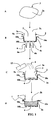
- the figure 1 schematically illustrates four steps (A to D) of the production of culture media 1 according to a first embodiment.
- step A we take a flexible envelope 2 having a first portion 2a of flexible envelope 2.
- This flexible envelope 2 is made of a flexible material which is selected from those suitable for crops above ground. This flexible material will be advantageously biodegradable and compostable.
- the first portion 2a of flexible envelope is positioned in a mold 5.
- the mold 5 shown comprises, for simplification, a single cell 5a, a peripheral wall 10a, a bottom 10b and peripheral sidewalks 10c.
- the first portion 2a of flexible envelope 2 is pressed to be brought into contact with the inner wall of the cell 5a and form an open pocket 3 with an opening face 3a.
- suction means 6 which suck the air present between the outer face of the pocket 3 and the inner face of the cell 5a through the pipes 6a-6c.
- the manufacture (not shown) of culture media may more preferably be performed in a multi-cell mold to produce either multi-compartment culture media or a plurality of detachable or detached culture media.
- step C culture substrate 4, contained in a reservoir 19, is poured into the bag 3 opened by the opening face 3a.
- the culture substrate 4 fills the bag 3 open, which is still held by the cell 5a of the mold 5.
- step D the bag 3 remaining engaged and held in the cavity 5a of the mold 5, is positioned a second portion 2b of flexible envelope 2 above the opening 3a of the bag 3. Then, the bag 3 is closed by means of closure means of the bonding, welding or sewing type. These closure means can be supported on the sidewalks 10c of the mold 5, to improve the assembly of the first 2a and second 2b portions of flexible envelope 2. A culture support 1 is thus obtained.
- Cutting means 9 may be implemented to remove unnecessary parts of flexible material if they do not have to fulfill the role of flap of the culture support 1. Thus we obtain a finished culture support.
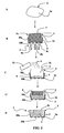
- the figure 2 illustrates a second embodiment of the manufacture of culture media. This figure illustrates five steps A, B, C, C 'and D, steps A, B, C and D being the same as in the embodiment of FIG. figure 1 , except for step B in which the action of pressing means 7 is added.
- the same essential means are identified by the same numerical references as on the figure 1 .
- the main differences lie in the mold 5 which comprises only a partial sidewalk, and in a step C 'inserted after step C and before step D, during which the substrate is compressed with compression means 8 4 of step D is different in this embodiment, in that it is the same flexible envelope 2 which is folded back on itself to form the second portion 2b of flexible envelope and close the pocket, thus forming the culture support 1.
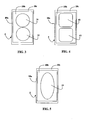
- FIGS. 3, 4 and 5 illustrate three examples of mold shapes. Each figure illustrates a mold 5 comprising a peripheral wall 10a, a bottom 10b and a sidewalk 10c.
- the mold of the figure 3 comprises two circular cells 31 and 32.
- the mold of the figure 4 comprises two cells 41 and 42 of square shape.
- the mold of the figure 5 comprises a single cell 51 of oval shape.
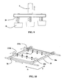
- the figure 6 illustrates a device for the manufacture of culture media.
- the device comprises a chassis 100 comprising an upper raceway 110 and a lower raceway 120, on which carriages 13, 17 and 21 move, the respective functions of which are described below.
- the manufacturing device is illustrated here with a mold 5 having three rectangular cells 5a, 5b and 5c.
- the frame 100 supports at one end a roll 60 of flexible strip material 22 whose width corresponds to the length of the culture medium that is to be obtained, in order to have the shortest displacements and consequently the production rate the higher.
- the device also comprises a winder-reel device 18 near the roller 60.
- a first carriage is a distribution carriage 13 which can be moved on the lower raceway 120, between a loading position (shown in the figure) in which it is placed under a loading station 23, and a dispensing position in which it is facing a mold support 14.
- the second carriage is an unwind carriage 17 which can be moved on the upper raceway 110.
- the third carriage is a welding carriage 21 which can be moved on the lower raceway 120.
- the welding carriage 21 comprises welding heads 21a.
- the device illustrated on the figure 6 also comprises pressing means 7 connected to the unwinding carriage 17 and able to be moved vertically towards and away from the mold support 14.
- the unwinding trolley 17 ensures the unfolding and the positioning above the mold 5 of the web of flexible material in web 22 from the roll 60.
- the web of flexible material strip 22 passes through an automatic device winder-winder 18 which maintains constant tension the web of flexible material strip 22.
- the mold support 14 comprises a mold 5 with three cavities 5a, 5b and 5c.
- the dispensing carriage 13 comprises a culture substrate reservoir 19.
- the bottom of this culture substrate reservoir 19 comprises movable traps 25.
- the opening of these hatches 25 ( figure 11 ) mobile causes the transfer of the culture substrate 4 from the culture substrate reservoir 19 to the cells 5a, 5b and 5c of the mold 5.
- An equivalent embodiment would consist in providing only one hatch in the bottom of the reservoir of growing medium 19.
- the applicator device 20 is removable and can be detached from the culture substrate reservoir 19. When the mold 5 is changed, it is thus possible to change the applicator device 20 and to choose such a device which is adapted to the shape of the mold 5 used. (for example the number and shape of the cells).
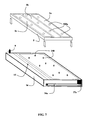
- the figure 7 illustrates in more detail an embodiment of mold 5 and mold support 14.
- the bottom 10b ( figure 11 ) of the mold 5 may include lights 500a for passing pre-cut knives 140 located at the bottom of the mold support 14. These pre-cut knives 140 make small cross-shaped incisions in the web of the flexible web material 22 to locate the sites intended to receive the plants and facilitate, at the time of planting, the establishment of mini-clumps in the culture medium.
- the pressing means 7 are used to press the web of the flexible web material 22 at the bottom of the cells 5a, 5b and 5c of the mold 5. This operation may optionally be associated with suction in the mold 5 to promote the installation of the soft material in strip 22 at the bottom.
- the aspiration we are discussing here is similar to that explained in the description of figures 1 and 2 .
- the pressing means 7 may comprise one or more punches 26 in correlation with the mold 5 used.
- the punches 26 are mounted on springs 29 and are offset at rest vertically ( figure 9 ) for successive interventions so that they push the flexible material in a band gradually to the bottom of the cells 5a, 5b and 5c of the mold 5 after each other with a shift in time.
- the punches 26 are complementary solid forms of the cells 5a, 5b and 5c of the mold 5.
- the pressing means 7 are also used to ensure, after filling and before closure, a slight settlement of the culture substrate 4 in the cells 5a, 5b and 5c of the mold 5, and at the same time to make the pre-cut knives 140 penetrate into the mold. 1 of the flexible web material 22.
- the mold 5 is placed in the recess of the mold support 14.
- the top of the mold 5 is flush with the upper edges of the mold support 14.
- the mold 5 is placed on a system of springs and guided so that it can be slightly embedded in the mold support 14 when the punches 26 of the pressing device 7 go down to compact the culture substrate 4 in the mold 5 in order to penetrate into the web of the flexible web material 22 the knives of pre-cut 140 ( figure 7 ) which pass through the lights 500a ( figure 7 ) made in the bottom of the mold 5.
- a pinch device 15 is provided ( figure 6 ) of the web flexible material 22, consisting for example of a movable door hinged about an axis. After introducing the end of the web of flexible web material 22 by drive rollers 28, the clamping device 15 closes and presses the web along its entire width and holds it firmly in place during the unwinding phases of the web. flexible web material, introduction of the culture substrate 4, and assembly. It is expected that the clamping device 15 opens at the time of extraction of the culture support 1 terminated by extraction arms 16a and 16b ( figure 8 ).
- the unwinding carriage 17 of the flexible strip material 22 is positioned above the support of the mold 14.
- the driving rollers 28 of the web of the flexible web material 22 descend the latter into the clamping device 15 which closes. and maintains the end of the flexible web material 22.
- the unwinding carriage 17 then moves in translation to the right ( figure 6 ) on the upper raceway 110, a pitch corresponding to the width of the mold support 14, while allowing the reeling of the flexible web material 22, so that the web of flexible web material 22 is deployed at above the mold 5 to form the first portion 2a of flexible envelope ( figure 1 ).
- the pressing means 7 descend to press the flexible web material 22 at the bottom of the cells 5a, 5b and 5c of the mold 5, and are then retracted.
- the dispensing carriage 13 containing the culture substrate 4 is positioned above the mold 5, in the dispensing position.
- the mold support 14 mounts to press the flexible web material 22 between the upper face of the mold 5 and the underside of the dispensing means 13, which has the effect of maintaining the flexible web material 22 and protecting the zones of the web. band flexible material 22 which will be subsequently assembled to close the bag after filling with the culture substrate 4.
- the movable traps of the culture substrate reservoir 19 open, causing the culture substrate 4 contained in the culture substrate reservoir 19 to flow through the applicator device 20, provided with separators 24 with a triangular section. .
- the culture substrate 4 fills the pockets formed in the cells 5a, 5b and 5c of the mold 5.
- the separators 24 guide the culture substrate 4 to the pockets of the cells 5a, 5b and 5c of the mold 5, avoiding any contamination of the parts flexible web material 22 which surrounds the cells and will then be used for assembly and for closing the culture support 1.
- the pressing means 7 descend again and the punches 26 tamp the culture substrate 4 in the pockets of the cells 5a, 5b and 5c of the mold 5. At the same time, the pressing means 7 cause, if desired, penetration of the knives. pre-cut 140 located at the bottom of the mold support 14, which pass through the lights 500a ( figure 7 ) made at the bottom 10b of the mold 5 and which perforate the web of the flexible web material 22 by causing cross cuts therein.
- the pressing means 7 go up, the mobile hatches 25 of the distribution means 13 close, the mold support 14 goes down, the distribution means 13 return to the recharging station 23 as a culture substrate.
- Holding fingers 27a and 27b located at the end of the extraction arms 16a and 16b ( figure 8 ) articulated on the support of the mold 14, exit and block the web of flexible material strip 22 on the mold support 14.
- the unwinding carriage 17 is directed to the left ( figure 6 ) so that the web of the flexible web material 22 folds on itself.
- the unwinding carriage 17 moves in translation with a pitch corresponding to the width of the mold support 14, to the left until the mold support 14 is completely released, leaving enough space to extract the culture support 1 when will be done.
- the web of the flexible web material 22, held by the holding fingers 27a and 27b ( figures 6 and 8 ), is deployed above the mold 5 and folds on the previous layer, forming the second portion 2b of flexible envelope ( figure 1 ).
- the flexible web material 22 is held in slight tension by the drive rollers 28 to facilitate the sliding of the welding heads 21a.
- the welding carriage 21, which carries the welding heads 21a, is positioned above the mold 5.
- the mold support 14 mounts to ensure a pressure of the welding heads 21a on the flexible web material 22.
- the two axes of displacement X and Y ( figure 10 ) of the welding carriage 21 are controlled by a programmable electronic system.
- Welding heads 21 a describe the path or paths required to weld the outer edges of the culture support 1 as well as possible partitions.
- the programmable system also manages the power supply of welding heads 21a which are turned on or off at the appropriate times of the trajectory.
- the culture support 1 is completely closed and the partitions if there are any.
- the mold support 14 moves down to release the pressure on the welding heads 21a.
- the welding carriage 21 returns to its waiting position to the right of the device (on the figure 6 ).
- a cutting device 9 may be provided in front of the clamping device 15, resting on the upper edge of the mold support 14, a cutting device 9 may be provided. It may be for example a rotary steel roller having a cutting edge. The cut of the web of flexible material in strip 22 is obtained by causing the roller to execute a translational movement while exerting a strong pressure of the roller on the flexible web material 22.
- the cutting device 9 separates the completed culture support 1 from the web of the flexible web material 22 from the roll 60.
- extraction arms 16a and 16b On both sides of the mold support 14 are present the extraction arms 16a and 16b, illustrated more precisely on the figure 8 . These extraction arms 16a and 16b carry at their ends two holding fingers 27a and 27b.
- the holding fingers 27a and 27b have a triple role: to maintain the web of flexible material in band 22 to allow it to fold back on itself after the filling of the cells in culture substrate 4, to allow the maintenance of a slight tension of the web. flexible material in band 22 during the assembly operation, and allow the extraction of the finished culture support 1.
- the extraction arms 16a and 16b are raised by driving the culture support 1 by the holding fingers 27a and 27b which are inside the portion of the web of the flexible web material 22 folded on itself. The subsequent withdrawal of the holding fingers 27a and 27b causes the release of the culture support 1.
- the extraction arms 16a and 16b articulated on the mold support 14 are raised by describing a circular arc.
- the culture support 1 is extracted from the cells 5a, 5b and 5c of the mold 5.
- the holding fingers 27a and 27b are retracted, the culture support 1 falls on a conveyor belt and is evacuated.
- the cells 5a, 5b and 5c of the mold 5 have rounded edges with a slight slope.
- the mold 5 has a thickness of only a few centimeters. Such a thickness is sufficient for an aboveground crop support, the length and width of which are generally several tens of centimeters, for example 50 cm ⁇ 100 cm. Such a configuration avoids too much wrinkling of the web of the flexible material in band 22, which fold would hinder the assembly.
- the mold 5 is interchangeably reported in the mold support 14.
- the welding carriage 21 of the figure 6 which carries the welding heads 21a, can be designed to gain efficiency and increase productivity, in the form of a table with orthogonal displacements along two axes X and Y illustrated on the figure 10 .
- This arrangement allows, by a suitable electronic control, to describe to one or more welding heads 21 has any curve in a plane. It is then possible to assemble culture supports of square, rectangular, round, oval, with or without internal separations.
- the welding carriage 21 is driven by a motor 70, driven by a programmable electronic device adapted to move it along at least one horizontal axis.
- the welding carriage 21 carries two other mobile carriages 210a and 210b. These two carriages 210a and 210b are each driven by a motor 30a, 30b driven by a suitable programmable electronic device.
- the movable carriages 210a and 210b receive the welding heads 21a and can move independently of each other along the vertical axis. This arrangement allows the welding of the flexible web material 22 by several welding heads 21a operating simultaneously, the carriages 210a and 210b going to meet one another. The distance to be traveled is thus practically halved, the welding time is reduced by the same amount.
- the welding heads 21a are arranged individually on removable spring-loaded supports on the mobile carriages 210a and 210b. When manufactures require it, some of the welding heads 21a can be removed or moved.
- another method of implementing the method using an automatic manufacturing device makes it possible to produce culture media with two strips of different strip materials.
- This mode is particularly suitable when, for technical or aesthetic reasons, it is necessary to use two flexible materials strip different in their thickness, composition, color.
- the device then comprises a first coil of flexible textile material which is unwound from the pitch corresponding to the width of the mold. To be easily interchangeable the coil is housed in the mold holder.
- the dispensing means contain, in the culture substrate reservoir, the dose of culture substrate necessary for filling the cells of the mold.
- the alternative may be a bonding assembly using an adhesive. It is at this stage of the embodiment that the adhesive is sprayed onto the portions of the web of the flexible web material apparent in the mold. This coating operation of the adhesive can be combined with the deposition of the culture substrate by the dispensing means when the applicator is in contact with the flexible material strip in the mold. Adhesive injectors are then integrated into the applicator. This operation does not take place if the assembly is made by welding.
- the second web of the flexible web material is unwound from the pitch corresponding to the width of the mold, and according to the selected assembly technology, the second web of the flexible web material is pressed onto the glued portions with, depending on the nature of the adhesive, simply waiting for its cooling or heating by heating or radiation polymerization uitraviolet for example, or any other suitable technical means.
- the second web of the flexible web material may also be welded by the welding heads as explained in the previous embodiment.
- a device cuts the two webs of flexible web material.
- the culture medium is thus finished filled with culture substrate, closed, optionally partitioned.
- the extraction of the culture support can be obtained by tilting of the mold support, which ejects the culture support.
- This automatic manufacturing method is particularly suitable if one wants to use two different textile films in their thickness or composition.
- another way of implementing the method consists, in order to manufacture culture supports of very specific shape or dimensions, to cut the strips of the flexible material into strips before they are put into place in the preform mold. .
- the pieces of flexible material in strips thus prepared are then placed in the mold by hand and pressed into the bottom of the cell by manual pressing with a suitably shaped punch, which may possibly be associated with suction at the bottom of the mold. mold.
- a cover corresponding to the shape and the size of the mold is placed on the piece of the flexible strip material to preserve soiling areas that will be glued or welded.
- the packing in culture substrate is done manually.
- the culture substrate is deposited on the cover which partially covers the mold, and the cells are filled.
- a squeegee passed by hand on the cover eliminates the surplus of substrate.
- the cache is removed.
- the adhesive is deposited manually on the parts reserved with the aid of a glue gun, and the second piece of flexible material in strip, which may be identical or different from the previous one in its composition, its thickness or its color, is plated on the mold. It takes a few seconds to take the adhesive and unmold. In the case where the two pieces of flexible strip material are of the same composition they can be welded or glued.
- This manual method of obtaining is suitable for manufacturing in small series, intended to form culture media of very particular shape such as for example: heart, flower petal, crown, rhombus. Indeed, to obtain such shapes and avoid excessive pleating of the piece of the flexible web material that fills the mold, which would make the welding or bonding unrealizable with the piece of flexible material in the closure band, it is necessary to prepare the first piece of flexible strip material introduced into the mold by cutting it into a template or by making judicious cuts.
- the figure 12 illustrates a use of a culture support manufactured by a device similar to that described above and according to a method similar to that described above.
- the culture support 1 was shaped in a mold comprising four cells with a rectangular contour.
- the culture support 1 comprises four rectangular pockets P1, P2, P3 and P4.
- the peripheral cutting means cut the culture support around the periphery of the mold.
- Three strips B12, B23 and B34 of flexible strip material make the separation between the pockets P1, P2, P3 and P4, previously filled with culture substrate.
- This culture support 1 folded accordion can then be introduced into a gardening pan J.
- An advantage of such an accordion use is to easily fill a deep planter from a thin culture medium.
Landscapes
- Life Sciences & Earth Sciences (AREA)
- Environmental Sciences (AREA)
- Apparatus Associated With Microorganisms And Enzymes (AREA)
- Cultivation Receptacles Or Flower-Pots, Or Pots For Seedlings (AREA)
Claims (15)
- Verfahren zum Herstellen von Trägem (1) erdloser Kulturen, umfassend die folgenden Schritte:- Bereitstellen eines ersten Teils (2a) einer biegsamen Hülle (2),- in Form bringen und Halten des ersten Teils (2a) der biegsamen Hülle (2) zur Herstellung wenigstens einer Tasche (3) mit einer Öffnungsseite (3a), wozu der erste Teil (2a) der biegsamen Hülle (2) in eine Form (5) eingesaugt und/oder eingedrückt wird, um diesen ersten Teil (2a) der Hülle (2) in seine Form zu bringen,- Einfüllen eines Kultursubstrats (4) durch die Öffnungsseite (3a) in die in der Form (5) gehaltene Tasche (3),- Schließen der Öffnungsseite (3a) der Tasche (3) durch einen zweiten Teil (2b) der biegsamen Hülle (2), wodurch der das Kultursubstrat (4) aufnehmende Träger (1) gebildet wird.
- Verfahren nach Anspruch 1, dadurch gekennzeichnet, dass der erste Teil (2a) und der zweite Teil (2b) der biegsamen Hülle (2) aus einer einzigen Stoffbahn gebildet werden, die auf sich selbst umgelegt wird.
- Verfahren nach Anspruch 1, dadurch gekennzeichnet, dass der erste Teil (2a) und der zweite Teil (2b) der biegsamen Hülle (2) aus zwei getrennten Stoffbahnen gebildet werden.
- Verfahren nach einem der Ansprüche 1 bis 3, dadurch gekennzeichnet, dass das Schließen durch Schweißen, Kleben oder Nähen erfolgt.
- Verfahren nach einem der Ansprüche 1 bis 4, dadurch gekennzeichnet, dass das Einfüllen des Kultursubstrats (4) in die Tasche (3) durch eine Komprimierung des Kultursubstrats (4) in der Tasche (3) ergänzt wird.
- Verfahren nach einem der Ansprüche 1 bis 5, dadurch gekennzeichnet, dass nach dem Schließen der die Kultur aufnehmende Träger (1) auf dem Umfang beschnitten wird.
- Vorrichtung für die Herstellung von Trägern erdloser Kulturen unter Einsatz eines Verfahrens nach einem der vorhergehenden Ansprüche 1 bis 6, dadurch gekennzeichnet, dass diese umfasst:- wenigstens eine Form (5), die wenigstens eine Zelle (5a, 5b, 5c) mit einer umlaufenden Wand (10a), einem Boden (10b) und einer oberen Öffnungsseite hat,- Mitteln zum Halten (14) der Form, welche die Form (5) in einer vorbestimmten Arbeitsposition aufnehmen und halten können,- Fördermitteln (17) zum Zuführen eines ersten Teils (2a) der biegsamen Hülle (2) in der Nähe der vorbestimmten Arbeitsposition,- Klemmmitteln (15) zum Festklemmen des Endes des ersten Teils (2a) der biegsamen Hülle (2),- Mitteln (6, 7) zur Formgebung, um den ersten Teil (2a) der biegsamen Hülle (2) in die Zelle (5a, 5b, 5c) zu zwängen und eine Tasche (3) mit einer Öffnungsseite (3a) zu bilden,- Verteilmitteln (13) zum Einfüllen eines Kultursubstrats (4) durch die Öffnungsseite (3a) in der von der Zelle (5a, 5b, 5c) der Form (5) gehaltenen Tasche (3),- Schließmitteln zum Schließen der Öffnungsseite (3a) der Tasche (3) mittels eines zweiten Teils (2b) der biegsamen Hülle (2), um einen das Kultursubstrat (4) aufnehmenden Träger (1) zu bilden.
- Vorrichtung nach Anspruch 7, dadurch gekennzeichnet, dass die Mitteln zur Formgebung Ansaugmitteln (6) aufweisen, über die der erste Teil (2a) der biegsamen Hülle (2) in die Zelle (5a, 5b, 5c) gesaugt wird.
- Vorrichtung nach Anspruch 7 oder 8, dadurch gekennzeichnet, dass die Mitteln zur Formgebung Druckmitteln (7) aufweisen, deren Form der Form der Zelle (5a, 5b, 5c) entspricht und die so ausgebildet sind, dass sie den ersten Teil (2a) der biegsamen Hülle (2) gegen die Innenwand der Zelle (5a, 5b, 5c) drücken können.
- Vorrichtung nach einem der Ansprüche 7 bis 9, dadurch gekennzeichnet, dass die Verteilmitteln (13) umfassen:- einen mobilen Behälter (19), der zwischen einer Befüllposition und einer Ausgabeposition beweglich ist, einen Boden mit Öffnungsmitteln (25) hat und so ausgebildet ist, dass er gegen die Öffnungsseite des ersten Teils (2a) der biegsamen Hülle (2) gebracht werden kann,- eine Übertragungsvorrichtung (20) mit einer Form, die über diejenige der Form (5) gelegt werden kann.
- Vorrichtung nach Anspruch 10, dadurch gekennzeichnet, dass:- die Mitteln zum Halten (14) der Form (5) diese zwischen einer unteren Wartestellung und einer oberen Arbeitsstellung bewegen,- der mobile Behälter (13) horizontal zwischen der Befüllposition und der Ausgabeposition verschiebbar ist,- der mobile Behälter (13) in der Ausgabeposition in Verbindung mit der Form (5) ist.
- Vorrichtung nach einem der Ansprüche 7 bis 11, dadurch gekennzeichnet, dass die Form (5) Randflächen (10c) hat und dass die Schließmitteln Mitteln zum Verbinden des ersten Teils (2a) mit dem zweiten Teil (2b) der biegsamen Hülle (2) aufweisen.
- Vorrichtung nach einem der Ansprüche 10 oder 11, dadurch gekennzeichnet, dass die Übertragungsvorrichtung (20) außerdem Scheidewände (24) hat.
- Vorrichtung nach einem der Ansprüche 7 bis 13, dadurch gekennzeichnet, dass sie Mitteln (9) zum Umfangsbeschneiden des Kulturträgers (1) hat.
- Vorrichtung nach Anspruch 14, dadurch gekennzeichnet, dass die Mitteln (9) zum Umfangsbeschneiden des Kulturträgers (1) mit den Mitteln (6, 7) zur Formgebung synchronisiert sind.
Applications Claiming Priority (2)
| Application Number | Priority Date | Filing Date | Title |
|---|---|---|---|
| FR0857261A FR2937499B1 (fr) | 2008-10-25 | 2008-10-25 | Procede et dispositif pour la fabrication de supports de culture hors sol |
| PCT/IB2009/054698 WO2010046882A1 (fr) | 2008-10-25 | 2009-10-23 | Procede et dispositif pour la fabrication de supports de culture hors sol |
Publications (2)
| Publication Number | Publication Date |
|---|---|
| EP2364078A1 EP2364078A1 (de) | 2011-09-14 |
| EP2364078B1 true EP2364078B1 (de) | 2013-04-24 |
Family
ID=40578032
Family Applications (1)
| Application Number | Title | Priority Date | Filing Date |
|---|---|---|---|
| EP09744768.4A Active EP2364078B1 (de) | 2008-10-25 | 2009-10-23 | Verfahren und vorrichtung zur herstellung von stützen für erdlose kultivierung |
Country Status (4)
| Country | Link |
|---|---|
| EP (1) | EP2364078B1 (de) |
| FR (1) | FR2937499B1 (de) |
| MA (1) | MA32809B1 (de) |
| WO (1) | WO2010046882A1 (de) |
Family Cites Families (6)
| Publication number | Priority date | Publication date | Assignee | Title |
|---|---|---|---|---|
| GB2069973A (en) * | 1980-02-27 | 1981-09-03 | Mckenzie A E Co Ltd | Growing bag assembly |
| FR2610604B1 (fr) * | 1987-02-06 | 1990-12-07 | Florpack Sa | Revetement perfectionne pour conteneurs de fleurs et de plants |
| US5088231A (en) * | 1987-03-04 | 1992-02-18 | Agristar, Inc. | Automated system for micropropagation and culturing organic material |
| FR2663627B1 (fr) * | 1990-06-20 | 1993-05-21 | Ccm Compost Champi Maine | Procede de conditionnement en continu de paves de substrat pour la culture des champignons et dispositif pour sa mise en óoeuvre. |
| DE29503009U1 (de) * | 1995-02-23 | 1995-06-14 | Dedden, Lothar, 26160 Bad Zwischenahn | Pflanzsubstrat |
| NL1016938C2 (nl) * | 2000-12-21 | 2002-02-25 | Legro Potgrondbedrijf B V | Zak met groeibodemmateriaal en werkwijze voor het gebruik van een dergelijke zak. |
-
2008
- 2008-10-25 FR FR0857261A patent/FR2937499B1/fr not_active Expired - Fee Related
-
2009
- 2009-10-23 WO PCT/IB2009/054698 patent/WO2010046882A1/fr not_active Ceased
- 2009-10-23 EP EP09744768.4A patent/EP2364078B1/de active Active
-
2011
- 2011-05-19 MA MA33864A patent/MA32809B1/fr unknown
Also Published As
| Publication number | Publication date |
|---|---|
| MA32809B1 (fr) | 2011-11-01 |
| WO2010046882A1 (fr) | 2010-04-29 |
| FR2937499B1 (fr) | 2012-10-12 |
| FR2937499A1 (fr) | 2010-04-30 |
| EP2364078A1 (de) | 2011-09-14 |
Similar Documents
| Publication | Publication Date | Title |
|---|---|---|
| CH630025A5 (fr) | Chapelet de recipients identiques souples en matiere synthetique, et son procede de fabrication. | |
| EP0524464B1 (de) | Flexible Kaffeekassette mit einem versteifenden Element und Verfahren zu ihrer Herstellung | |
| EP0602203B1 (de) | Versiegelter flexibler beutel und verfahren zu dessen herstellen | |
| BE1005832A5 (fr) | Procede et appareillage de thermoformage et d'extraction d'objets creux munis d'un fond a partir d'une bande de matiere thermoplastique. | |
| EP0468079B1 (de) | Geschlossene Patrone zur Zubereitung eines Getränkes sowie Verfahren und Einrichtung zur Herstellung derselben | |
| FR2530123A1 (fr) | Procede et appareil de preparation de boisson | |
| FR2527173A1 (fr) | Conditionnement pour preparation d'infusions, buse pour un tel conditionnement, magasin de tels conditionnements, et procede et appareil de distribution de boissons infusees | |
| FR2730139A1 (fr) | Appareil et procede pour decouper en elements des pieces pour des vetements faits sur mesure | |
| FR2766123A1 (fr) | Installation et procede de fabrication de recipients par thermoformage | |
| EP0532403B1 (de) | Verfahren und Vorrichtung zur industriellen Produktion erdloser Pflanzenkultur | |
| CH649497A5 (fr) | Procede de fabrication d'un recipient avec une ouverture. | |
| CA3033432A1 (fr) | Procede et installation de fabrication de compresses a effet refroidissant et compresses obtenues en conditionnement sterile | |
| EP1415919A1 (de) | Verfahren und Vorrichtung zum Befüllen von Verpackungsschalen mit einem Nahrungsmittel | |
| EP1227978B1 (de) | Anordnung und verfahren zum herstellen von einzelnen aufgiessdosen | |
| EP0351289A1 (de) | Maschine zum kontinuierlichen Verpacken von Produkten, insbesondere von Nahrungsmitteln oder pharmazeutischen Produkten, in Kunststoffbehältern | |
| EP2364078B1 (de) | Verfahren und vorrichtung zur herstellung von stützen für erdlose kultivierung | |
| BE896729A (fr) | Distribution de boissons. | |
| WO2020120616A1 (fr) | Procédé et machine de formation de sacs flexibles à fond spécial | |
| EP1386839B1 (de) | Verfahren und Maschine für integrierte Formung zum Herstellen von nichtentformbaren Bechern | |
| FR2979904A1 (fr) | Recharge en dose unitaire pour un produit alimentaire et machine pour sa fabrication. | |
| FR2971488A1 (fr) | Dispositif de remplissage de sachets | |
| EP0868286A1 (de) | Gegenstand mit zwei flüssigkeitsdurchlassigen oberflachen | |
| EP0151364A2 (de) | Verpackungsstrasse für Produkte mit einem Film in einem aus einem flachen vorgeschnittenen Zuschnitt hergestellten Behälter | |
| FR2493104A1 (fr) | Unite de moulage de produits charcutiers et dispositif pour sa mise en oeuvre | |
| WO2001087098A1 (fr) | Procede, dispositif et installation pour confectionner un produit comestible compose de deux tranches enserrant un fourrage |
Legal Events
| Date | Code | Title | Description |
|---|---|---|---|
| PUAI | Public reference made under article 153(3) epc to a published international application that has entered the european phase |
Free format text: ORIGINAL CODE: 0009012 |
|
| 17P | Request for examination filed |
Effective date: 20110422 |
|
| AK | Designated contracting states |
Kind code of ref document: A1 Designated state(s): AT BE BG CH CY CZ DE DK EE ES FI FR GB GR HR HU IE IS IT LI LT LU LV MC MK MT NL NO PL PT RO SE SI SK SM TR |
|
| DAX | Request for extension of the european patent (deleted) | ||
| GRAP | Despatch of communication of intention to grant a patent |
Free format text: ORIGINAL CODE: EPIDOSNIGR1 |
|
| RIN1 | Information on inventor provided before grant (corrected) |
Inventor name: MITTON, BERNARD |
|
| GRAS | Grant fee paid |
Free format text: ORIGINAL CODE: EPIDOSNIGR3 |
|
| GRAA | (expected) grant |
Free format text: ORIGINAL CODE: 0009210 |
|
| RIN1 | Information on inventor provided before grant (corrected) |
Inventor name: GUILLEMAIN, JEAN-SYLVAIN Inventor name: BUGEON (EPOUSE) GUILLEMAIN, FRANCOISE Inventor name: MITTON, BERNARD |
|
| AK | Designated contracting states |
Kind code of ref document: B1 Designated state(s): AT BE BG CH CY CZ DE DK EE ES FI FR GB GR HR HU IE IS IT LI LT LU LV MC MK MT NL NO PL PT RO SE SI SK SM TR |
|
| REG | Reference to a national code |
Ref country code: GB Ref legal event code: FG4D Free format text: NOT ENGLISH |
|
| REG | Reference to a national code |
Ref country code: CH Ref legal event code: EP |
|
| RIN2 | Information on inventor provided after grant (corrected) |
Inventor name: MITTON, BERNARD Inventor name: GUILLEMAIN, JEAN-SYLVAIN Inventor name: BUGEON (EPOUSE) GUILLEMAIN, FRANCOISE |
|
| REG | Reference to a national code |
Ref country code: AT Ref legal event code: REF Ref document number: 607990 Country of ref document: AT Kind code of ref document: T Effective date: 20130515 |
|
| REG | Reference to a national code |
Ref country code: IE Ref legal event code: FG4D Free format text: LANGUAGE OF EP DOCUMENT: FRENCH |
|
| REG | Reference to a national code |
Ref country code: DE Ref legal event code: R096 Ref document number: 602009015242 Country of ref document: DE Effective date: 20130620 |
|
| REG | Reference to a national code |
Ref country code: CH Ref legal event code: NV Representative=s name: WAGNER PATENT AG, CH |
|
| REG | Reference to a national code |
Ref country code: AT Ref legal event code: MK05 Ref document number: 607990 Country of ref document: AT Kind code of ref document: T Effective date: 20130424 |
|
| REG | Reference to a national code |
Ref country code: NL Ref legal event code: T3 |
|
| REG | Reference to a national code |
Ref country code: LT Ref legal event code: MG4D |
|
| PG25 | Lapsed in a contracting state [announced via postgrant information from national office to epo] |
Ref country code: ES Free format text: LAPSE BECAUSE OF FAILURE TO SUBMIT A TRANSLATION OF THE DESCRIPTION OR TO PAY THE FEE WITHIN THE PRESCRIBED TIME-LIMIT Effective date: 20130804 Ref country code: FI Free format text: LAPSE BECAUSE OF FAILURE TO SUBMIT A TRANSLATION OF THE DESCRIPTION OR TO PAY THE FEE WITHIN THE PRESCRIBED TIME-LIMIT Effective date: 20130424 Ref country code: AT Free format text: LAPSE BECAUSE OF FAILURE TO SUBMIT A TRANSLATION OF THE DESCRIPTION OR TO PAY THE FEE WITHIN THE PRESCRIBED TIME-LIMIT Effective date: 20130424 Ref country code: GR Free format text: LAPSE BECAUSE OF FAILURE TO SUBMIT A TRANSLATION OF THE DESCRIPTION OR TO PAY THE FEE WITHIN THE PRESCRIBED TIME-LIMIT Effective date: 20130725 Ref country code: SI Free format text: LAPSE BECAUSE OF FAILURE TO SUBMIT A TRANSLATION OF THE DESCRIPTION OR TO PAY THE FEE WITHIN THE PRESCRIBED TIME-LIMIT Effective date: 20130424 Ref country code: NO Free format text: LAPSE BECAUSE OF FAILURE TO SUBMIT A TRANSLATION OF THE DESCRIPTION OR TO PAY THE FEE WITHIN THE PRESCRIBED TIME-LIMIT Effective date: 20130724 Ref country code: LT Free format text: LAPSE BECAUSE OF FAILURE TO SUBMIT A TRANSLATION OF THE DESCRIPTION OR TO PAY THE FEE WITHIN THE PRESCRIBED TIME-LIMIT Effective date: 20130424 Ref country code: PT Free format text: LAPSE BECAUSE OF FAILURE TO SUBMIT A TRANSLATION OF THE DESCRIPTION OR TO PAY THE FEE WITHIN THE PRESCRIBED TIME-LIMIT Effective date: 20130826 Ref country code: IS Free format text: LAPSE BECAUSE OF FAILURE TO SUBMIT A TRANSLATION OF THE DESCRIPTION OR TO PAY THE FEE WITHIN THE PRESCRIBED TIME-LIMIT Effective date: 20130824 Ref country code: SE Free format text: LAPSE BECAUSE OF FAILURE TO SUBMIT A TRANSLATION OF THE DESCRIPTION OR TO PAY THE FEE WITHIN THE PRESCRIBED TIME-LIMIT Effective date: 20130424 |
|
| PG25 | Lapsed in a contracting state [announced via postgrant information from national office to epo] |
Ref country code: CY Free format text: LAPSE BECAUSE OF FAILURE TO SUBMIT A TRANSLATION OF THE DESCRIPTION OR TO PAY THE FEE WITHIN THE PRESCRIBED TIME-LIMIT Effective date: 20130424 Ref country code: LV Free format text: LAPSE BECAUSE OF FAILURE TO SUBMIT A TRANSLATION OF THE DESCRIPTION OR TO PAY THE FEE WITHIN THE PRESCRIBED TIME-LIMIT Effective date: 20130424 Ref country code: BG Free format text: LAPSE BECAUSE OF FAILURE TO SUBMIT A TRANSLATION OF THE DESCRIPTION OR TO PAY THE FEE WITHIN THE PRESCRIBED TIME-LIMIT Effective date: 20130724 Ref country code: HR Free format text: LAPSE BECAUSE OF FAILURE TO SUBMIT A TRANSLATION OF THE DESCRIPTION OR TO PAY THE FEE WITHIN THE PRESCRIBED TIME-LIMIT Effective date: 20130424 Ref country code: PL Free format text: LAPSE BECAUSE OF FAILURE TO SUBMIT A TRANSLATION OF THE DESCRIPTION OR TO PAY THE FEE WITHIN THE PRESCRIBED TIME-LIMIT Effective date: 20130424 |
|
| PG25 | Lapsed in a contracting state [announced via postgrant information from national office to epo] |
Ref country code: CZ Free format text: LAPSE BECAUSE OF FAILURE TO SUBMIT A TRANSLATION OF THE DESCRIPTION OR TO PAY THE FEE WITHIN THE PRESCRIBED TIME-LIMIT Effective date: 20130424 Ref country code: DK Free format text: LAPSE BECAUSE OF FAILURE TO SUBMIT A TRANSLATION OF THE DESCRIPTION OR TO PAY THE FEE WITHIN THE PRESCRIBED TIME-LIMIT Effective date: 20130424 Ref country code: EE Free format text: LAPSE BECAUSE OF FAILURE TO SUBMIT A TRANSLATION OF THE DESCRIPTION OR TO PAY THE FEE WITHIN THE PRESCRIBED TIME-LIMIT Effective date: 20130424 Ref country code: SK Free format text: LAPSE BECAUSE OF FAILURE TO SUBMIT A TRANSLATION OF THE DESCRIPTION OR TO PAY THE FEE WITHIN THE PRESCRIBED TIME-LIMIT Effective date: 20130424 |
|
| PG25 | Lapsed in a contracting state [announced via postgrant information from national office to epo] |
Ref country code: RO Free format text: LAPSE BECAUSE OF FAILURE TO SUBMIT A TRANSLATION OF THE DESCRIPTION OR TO PAY THE FEE WITHIN THE PRESCRIBED TIME-LIMIT Effective date: 20130424 Ref country code: IT Free format text: LAPSE BECAUSE OF FAILURE TO SUBMIT A TRANSLATION OF THE DESCRIPTION OR TO PAY THE FEE WITHIN THE PRESCRIBED TIME-LIMIT Effective date: 20130424 |
|
| PLBE | No opposition filed within time limit |
Free format text: ORIGINAL CODE: 0009261 |
|
| STAA | Information on the status of an ep patent application or granted ep patent |
Free format text: STATUS: NO OPPOSITION FILED WITHIN TIME LIMIT |
|
| REG | Reference to a national code |
Ref country code: CH Ref legal event code: PCAR Free format text: NEW ADDRESS: BAECHERSTRASSE 9, 8832 WOLLERAU (CH) |
|
| 26N | No opposition filed |
Effective date: 20140127 |
|
| REG | Reference to a national code |
Ref country code: DE Ref legal event code: R097 Ref document number: 602009015242 Country of ref document: DE Effective date: 20140127 |
|
| PG25 | Lapsed in a contracting state [announced via postgrant information from national office to epo] |
Ref country code: MC Free format text: LAPSE BECAUSE OF FAILURE TO SUBMIT A TRANSLATION OF THE DESCRIPTION OR TO PAY THE FEE WITHIN THE PRESCRIBED TIME-LIMIT Effective date: 20130424 |
|
| PGFP | Annual fee paid to national office [announced via postgrant information from national office to epo] |
Ref country code: IE Payment date: 20140919 Year of fee payment: 6 |
|
| PGFP | Annual fee paid to national office [announced via postgrant information from national office to epo] |
Ref country code: GB Payment date: 20141028 Year of fee payment: 6 Ref country code: DE Payment date: 20141218 Year of fee payment: 6 |
|
| PGFP | Annual fee paid to national office [announced via postgrant information from national office to epo] |
Ref country code: NL Payment date: 20141021 Year of fee payment: 6 |
|
| PGFP | Annual fee paid to national office [announced via postgrant information from national office to epo] |
Ref country code: BE Payment date: 20141014 Year of fee payment: 6 |
|
| PG25 | Lapsed in a contracting state [announced via postgrant information from national office to epo] |
Ref country code: SM Free format text: LAPSE BECAUSE OF FAILURE TO SUBMIT A TRANSLATION OF THE DESCRIPTION OR TO PAY THE FEE WITHIN THE PRESCRIBED TIME-LIMIT Effective date: 20130424 |
|
| PG25 | Lapsed in a contracting state [announced via postgrant information from national office to epo] |
Ref country code: TR Free format text: LAPSE BECAUSE OF FAILURE TO SUBMIT A TRANSLATION OF THE DESCRIPTION OR TO PAY THE FEE WITHIN THE PRESCRIBED TIME-LIMIT Effective date: 20130424 |
|
| PG25 | Lapsed in a contracting state [announced via postgrant information from national office to epo] |
Ref country code: HU Free format text: LAPSE BECAUSE OF FAILURE TO SUBMIT A TRANSLATION OF THE DESCRIPTION OR TO PAY THE FEE WITHIN THE PRESCRIBED TIME-LIMIT; INVALID AB INITIO Effective date: 20091023 Ref country code: LU Free format text: LAPSE BECAUSE OF NON-PAYMENT OF DUE FEES Effective date: 20131023 Ref country code: MK Free format text: LAPSE BECAUSE OF FAILURE TO SUBMIT A TRANSLATION OF THE DESCRIPTION OR TO PAY THE FEE WITHIN THE PRESCRIBED TIME-LIMIT Effective date: 20130424 |
|
| PG25 | Lapsed in a contracting state [announced via postgrant information from national office to epo] |
Ref country code: MT Free format text: LAPSE BECAUSE OF FAILURE TO SUBMIT A TRANSLATION OF THE DESCRIPTION OR TO PAY THE FEE WITHIN THE PRESCRIBED TIME-LIMIT Effective date: 20130424 |
|
| REG | Reference to a national code |
Ref country code: FR Ref legal event code: PLFP Year of fee payment: 7 |
|
| PGFP | Annual fee paid to national office [announced via postgrant information from national office to epo] |
Ref country code: CH Payment date: 20151029 Year of fee payment: 7 |
|
| REG | Reference to a national code |
Ref country code: DE Ref legal event code: R119 Ref document number: 602009015242 Country of ref document: DE |
|
| GBPC | Gb: european patent ceased through non-payment of renewal fee |
Effective date: 20151023 |
|
| REG | Reference to a national code |
Ref country code: NL Ref legal event code: MM Effective date: 20151101 |
|
| REG | Reference to a national code |
Ref country code: IE Ref legal event code: MM4A |
|
| PG25 | Lapsed in a contracting state [announced via postgrant information from national office to epo] |
Ref country code: GB Free format text: LAPSE BECAUSE OF NON-PAYMENT OF DUE FEES Effective date: 20151023 Ref country code: DE Free format text: LAPSE BECAUSE OF NON-PAYMENT OF DUE FEES Effective date: 20160503 |
|
| PG25 | Lapsed in a contracting state [announced via postgrant information from national office to epo] |
Ref country code: NL Free format text: LAPSE BECAUSE OF NON-PAYMENT OF DUE FEES Effective date: 20151101 |
|
| REG | Reference to a national code |
Ref country code: FR Ref legal event code: PLFP Year of fee payment: 8 |
|
| PG25 | Lapsed in a contracting state [announced via postgrant information from national office to epo] |
Ref country code: IE Free format text: LAPSE BECAUSE OF NON-PAYMENT OF DUE FEES Effective date: 20151023 |
|
| REG | Reference to a national code |
Ref country code: CH Ref legal event code: PL |
|
| PG25 | Lapsed in a contracting state [announced via postgrant information from national office to epo] |
Ref country code: LI Free format text: LAPSE BECAUSE OF NON-PAYMENT OF DUE FEES Effective date: 20161031 Ref country code: BE Free format text: LAPSE BECAUSE OF NON-PAYMENT OF DUE FEES Effective date: 20151031 Ref country code: CH Free format text: LAPSE BECAUSE OF NON-PAYMENT OF DUE FEES Effective date: 20161031 |
|
| REG | Reference to a national code |
Ref country code: FR Ref legal event code: PLFP Year of fee payment: 9 |
|
| REG | Reference to a national code |
Ref country code: FR Ref legal event code: PLFP Year of fee payment: 10 |
|
| PGFP | Annual fee paid to national office [announced via postgrant information from national office to epo] |
Ref country code: FR Payment date: 20250731 Year of fee payment: 17 |