EP2363534A2 - Schneeräumgerät - Google Patents
Schneeräumgerät Download PDFInfo
- Publication number
- EP2363534A2 EP2363534A2 EP10007955A EP10007955A EP2363534A2 EP 2363534 A2 EP2363534 A2 EP 2363534A2 EP 10007955 A EP10007955 A EP 10007955A EP 10007955 A EP10007955 A EP 10007955A EP 2363534 A2 EP2363534 A2 EP 2363534A2
- Authority
- EP
- European Patent Office
- Prior art keywords
- snow
- sack truck
- item
- sack
- clearing machine
- Prior art date
- Legal status (The legal status is an assumption and is not a legal conclusion. Google has not performed a legal analysis and makes no representation as to the accuracy of the status listed.)
- Withdrawn
Links
- 239000004952 Polyamide Substances 0.000 description 2
- 229920002647 polyamide Polymers 0.000 description 2
- 244000025254 Cannabis sativa Species 0.000 description 1
- 238000009825 accumulation Methods 0.000 description 1
- 230000006378 damage Effects 0.000 description 1
Images



Classifications
-
- E—FIXED CONSTRUCTIONS
- E01—CONSTRUCTION OF ROADS, RAILWAYS, OR BRIDGES
- E01H—STREET CLEANING; CLEANING OF PERMANENT WAYS; CLEANING BEACHES; DISPERSING OR PREVENTING FOG IN GENERAL CLEANING STREET OR RAILWAY FURNITURE OR TUNNEL WALLS
- E01H5/00—Removing snow or ice from roads or like surfaces; Grading or roughening snow or ice
- E01H5/02—Hand implements
-
- E—FIXED CONSTRUCTIONS
- E01—CONSTRUCTION OF ROADS, RAILWAYS, OR BRIDGES
- E01H—STREET CLEANING; CLEANING OF PERMANENT WAYS; CLEANING BEACHES; DISPERSING OR PREVENTING FOG IN GENERAL CLEANING STREET OR RAILWAY FURNITURE OR TUNNEL WALLS
- E01H5/00—Removing snow or ice from roads or like surfaces; Grading or roughening snow or ice
- E01H5/04—Apparatus propelled by animal or engine power; Apparatus propelled by hand with driven dislodging or conveying levelling elements, conveying pneumatically for the dislodged material
- E01H5/06—Apparatus propelled by animal or engine power; Apparatus propelled by hand with driven dislodging or conveying levelling elements, conveying pneumatically for the dislodged material dislodging essentially by non-driven elements, e.g. scraper blades, snow-plough blades, scoop blades
- E01H5/065—Apparatus propelled by animal or engine power; Apparatus propelled by hand with driven dislodging or conveying levelling elements, conveying pneumatically for the dislodged material dislodging essentially by non-driven elements, e.g. scraper blades, snow-plough blades, scoop blades characterised by the form of the snow-plough blade, e.g. flexible, or by snow-plough blade accessories
- E01H5/066—Snow-plough blade accessories, e.g. deflector plates, skid shoes
Definitions
- the Schneelux is a snow plow (item 1 of the figures in the sketch), which has been developed for the exclusive attachment of a sack truck. This attachment fits almost all sack trucks of current models with a spoon length of about 24 cm.
- the image is three times height adjustable and can therefore be adapted very well to the body size.
- the mounting of the recording on the sack truck is done by a central articulated foot (item 13), which adjusts in parallel in all three height adjustments, very fast and extremely simple.
- the articulated foot consists of a rubber pad and a cross handle (item 14).
- a rounded polyamide strip (item 5) on the underside of the label ensures a bumpless sliding sliding behavior.
- the top edge protection (item 15) is intended to prevent injuries.
- the receptacle consists of three parts: left side part (item 2), right side part (item 3) and one center bar (item 4).
- the side parts are without weld and screw connections in one piece.
- Another advantage of the snow removal device is that it achieves an improved snow accumulation behavior in the Basedndzone by pushing down the sack bar handles.
- skid attachment system For non-paved surfaces such as gravel, grass lattice, natural ground and lawn there is a skid attachment system as an accessory.
- the runners (item 16) are mounted on both sides of the snow blade in order to clear evenly on uneven surfaces.
Landscapes
- Engineering & Computer Science (AREA)
- Architecture (AREA)
- Civil Engineering (AREA)
- Structural Engineering (AREA)
- Cleaning Of Streets, Tracks, Or Beaches (AREA)
Abstract
Description
- Herkömmliche Schneeschaufeln können meist nicht über eine große Fläche gezogen werden, weil sonst der Schnee aufgrund der Lasten nicht mehr geschoben werden kann. Folglich ist das herkömmliche Schneeschieben oftmals sehr beschwerlich.
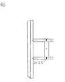
- Der Schneelux ist ein Schneeräumschild (Pos. 1 der in der Skizze beigefügten Figuren), das zum ausschließlichen Anbau für eine Sackkarre entwickelt worden ist. Diese Anbauvorrichtung passt bei fast allen Sackkarren der derzeit gängigen Modelle mit einer Löffellänge von ca. 24 cm.
- Die Aufnahme ist drei-fach höhenverstellbar und kann dadurch sehr gut der Körpergröße angepasst werden.
- Die Montage der Aufnahme an der Sackkarre erfolgt durch einen mittig liegenden Gelenkfuß (Pos. 13), der sich in allen drei Höhenverstellungen parallel anpasst, sehr schnell und äußerst einfach. Der Gelenkfuß besteht aus einer Gummiauflage und einem Kreuzgriff (Pos. 14).
- Eine abgerundete Polyamidleiste (Pos. 5) an der Unterseite des Schildes sichert ein stoßfreies gleitendes Schiebeverhalten. Der oben anliegende Kantenschutz (Pos. 15) soll Verletzungen verhindern.
- Die Aufnahme besteht aus drei Teilen: Linkes Seitenteil (Pos. 2), rechtes Seitenteil (Pos. 3) und eine Mittelstrebe (Pos. 4). Die Seitenteile sind ohne Schweiß- und Schraubenverbindungen aus einem Stück.
- Aufgrund der durchdachten Form des Schneeschildes und der Verwendung der Sackkarre kann man durch Zurückziehen des Schneeräumgerätes Schnee aus Ecken und Kanten heraus räumen.
- Ein weiterer Vorteil des Schneeräumgerätes besteht darin, dass man durch das Runterdrücken der Sackkarrengriffe ein verbessertes Schneeanhäufverhalten in der Räumendzone erzielt.
- Durch eine Arbeitsbreite von 90 cm kann man eine Grundstücksfläche von ca. 150 qm bei einer Schneehöhe von 5-8 cm in etwa 10 Minuten räumen. Mit einer herkömmlichen Schneeschaufel benötigt man für diese Fläche in etwa 90 Minuten.
- Für nicht befestigte Untergründe wie z.B. Schotter, Rasengitter, Naturboden und Rasen gibt es als Zubehör ein Kufenanbausystem. Die Kufen (Pos. 16) werden beidseits an das Schneeschild montiert, um auf unebenen Untergründen gleichmäßig räumen zu können.
-
Pos. Bezeichnung Stück 1 Räumschild 1 2 Aufnahme links 1 3 Aufnahme rechts 1 4 Strebe 1 5 Polyamidleiste 1 6 Schloßschraube M 6 x 25 ZN 6 7 Flachrundschraube mit Schlitz M 8 x 16 6 8 Sechskantmutter M 6 ZN 6 9 Sechskantmutter M 8 ZN 6 10 Sechskantmutter M 10 ZN 6 11 Sperrkantscheibe M 6 - 300351 6 6 12 Sperrkantscheibe M 8 - 300351 8 6 13 Schwenkklemmfuß 1 14 Sterngriffmutter 1 15 Kantenschutz 1 16 Kufe 2
Claims (4)
- Aufnahmeteil zwischen Sackkarre und Schneeschaufel,
dadurch gekennzeichnet,
dass das Ende der Sackkarre mittels eines Gelenkfußes einfach verbunden werden kann. - Aufnahmeteil zwischen Sackkarre und Schneeschaufel,
dadurch gekennzeichnet,
dass die Aufnahme der Sackkarre in 3 verschiedenen Höhen erfolgen kann. - Schneeräumgerät,
dadurch gekennzeichnet,
dass das Schneeräumgerät durch die Verwendung der Sachkarre das Rückziehen von Schnee aus Ecken und Kanten leichter ermöglicht. - Schneeräumgerät mit Kufen,
dadurch gekennzeichnet,
dass mittels der angebrachten Kufen das Schneeräumgerät auf unebenen Untergrund ohne Probleme verwendet werden kann und den Schnee damit beseitigt.
Applications Claiming Priority (1)
| Application Number | Priority Date | Filing Date | Title |
|---|---|---|---|
| DE201020003038 DE202010003038U1 (de) | 2010-03-03 | 2010-03-03 | Schneeräumgerät |
Publications (2)
| Publication Number | Publication Date |
|---|---|
| EP2363534A2 true EP2363534A2 (de) | 2011-09-07 |
| EP2363534A3 EP2363534A3 (de) | 2012-07-04 |
Family
ID=42979427
Family Applications (1)
| Application Number | Title | Priority Date | Filing Date |
|---|---|---|---|
| EP10007955A Withdrawn EP2363534A3 (de) | 2010-03-03 | 2010-07-29 | Schneeräumgerät |
Country Status (2)
| Country | Link |
|---|---|
| EP (1) | EP2363534A3 (de) |
| DE (1) | DE202010003038U1 (de) |
Family Cites Families (4)
| Publication number | Priority date | Publication date | Assignee | Title |
|---|---|---|---|---|
| US3473838A (en) * | 1967-12-20 | 1969-10-21 | William J Rankin | Snow removal device |
| US6560904B2 (en) * | 2001-06-15 | 2003-05-13 | Pro-Tech Welding And Fabrication, Inc. | Compact material pusher with universal design and method of manufacture |
| US20070068050A1 (en) * | 2005-09-26 | 2007-03-29 | Flanagan Daniel J | Hand truck-mountable snowplow |
| US20080067766A1 (en) * | 2006-09-19 | 2008-03-20 | Mark Watson | Snow removal device |
-
2010
- 2010-03-03 DE DE201020003038 patent/DE202010003038U1/de not_active Expired - Lifetime
- 2010-07-29 EP EP10007955A patent/EP2363534A3/de not_active Withdrawn
Non-Patent Citations (1)
| Title |
|---|
| None |
Also Published As
| Publication number | Publication date |
|---|---|
| EP2363534A3 (de) | 2012-07-04 |
| DE202010003038U1 (de) | 2010-10-14 |
Similar Documents
| Publication | Publication Date | Title |
|---|---|---|
| US8166677B1 (en) | Manual snow plow | |
| DE2617865A1 (de) | Vorrichtung zur bodenlockerung | |
| WO2017072170A1 (de) | Selbstfahrendes nutzflächen-bearbeitungsgerät | |
| EP2363534A2 (de) | Schneeräumgerät | |
| US20120006572A1 (en) | Stadium groomer | |
| US2886906A (en) | Ground leveling implement | |
| US20070068050A1 (en) | Hand truck-mountable snowplow | |
| DE102012004517A1 (de) | Bodenbearbeitungsgerät | |
| EP2747539A1 (de) | Ackerfräse | |
| RU2681127C1 (ru) | Прицепное устройство для подготовки лыжных трасс | |
| DE102011051223A1 (de) | Räumvorrichtung | |
| US20070012464A1 (en) | Grading apparatus | |
| US3036392A (en) | Telescoping land leveler | |
| EP3336263A1 (de) | Anbaugerät für eine arbeitsmaschine | |
| EP1788156A3 (de) | Handgeführtes Landschaftspflegegerät | |
| US5289879A (en) | Sandtrap maintenance machine rake assembly | |
| US20200208364A1 (en) | Adjustable snowplow | |
| US1179608A (en) | Road-drag. | |
| US11846084B2 (en) | Yard leveling and conditioning apparatus | |
| EP2557235A2 (de) | Anbaugerät; Verfahren zur Aufnahme von auf einem Boden gelagerten Schüttgut | |
| US2647356A (en) | Power-operated push rake | |
| DE29919571U1 (de) | Gerät zur Bearbeitung einer Bodenfläche | |
| DE3725769C1 (en) | Powered garden machine control system - incorporates frame fixed to handlebars with additional handgrips | |
| DE411128C (de) | Schlittenkufenanordnung fuer Ackerschleifen | |
| EP2054554B1 (de) | Planiergerät |
Legal Events
| Date | Code | Title | Description |
|---|---|---|---|
| PUAI | Public reference made under article 153(3) epc to a published international application that has entered the european phase |
Free format text: ORIGINAL CODE: 0009012 |
|
| AK | Designated contracting states |
Kind code of ref document: A2 Designated state(s): AL AT BE BG CH CY CZ DE DK EE ES FI FR GB GR HR HU IE IS IT LI LT LU LV MC MK MT NL NO PL PT RO SE SI SK SM TR |
|
| AX | Request for extension of the european patent |
Extension state: BA ME RS |
|
| PUAL | Search report despatched |
Free format text: ORIGINAL CODE: 0009013 |
|
| AK | Designated contracting states |
Kind code of ref document: A3 Designated state(s): AL AT BE BG CH CY CZ DE DK EE ES FI FR GB GR HR HU IE IS IT LI LT LU LV MC MK MT NL NO PL PT RO SE SI SK SM TR |
|
| AX | Request for extension of the european patent |
Extension state: BA ME RS |
|
| RIC1 | Information provided on ipc code assigned before grant |
Ipc: E01H 5/06 20060101ALI20120525BHEP Ipc: E01H 5/02 20060101AFI20120525BHEP |
|
| STAA | Information on the status of an ep patent application or granted ep patent |
Free format text: STATUS: THE APPLICATION IS DEEMED TO BE WITHDRAWN |
|
| 18D | Application deemed to be withdrawn |
Effective date: 20130105 |