EP2362349A2 - Kalibriervorrichtung - Google Patents
Kalibriervorrichtung Download PDFInfo
- Publication number
- EP2362349A2 EP2362349A2 EP11000505A EP11000505A EP2362349A2 EP 2362349 A2 EP2362349 A2 EP 2362349A2 EP 11000505 A EP11000505 A EP 11000505A EP 11000505 A EP11000505 A EP 11000505A EP 2362349 A2 EP2362349 A2 EP 2362349A2
- Authority
- EP
- European Patent Office
- Prior art keywords
- coordinates
- designating
- area
- manipulation
- reproducer
- Prior art date
- Legal status (The legal status is an assumption and is not a legal conclusion. Google has not performed a legal analysis and makes no representation as to the accuracy of the status listed.)
- Withdrawn
Links
Images








Classifications
-
- G—PHYSICS
- G06—COMPUTING OR CALCULATING; COUNTING
- G06T—IMAGE DATA PROCESSING OR GENERATION, IN GENERAL
- G06T7/00—Image analysis
- G06T7/80—Analysis of captured images to determine intrinsic or extrinsic camera parameters, i.e. camera calibration
-
- G—PHYSICS
- G06—COMPUTING OR CALCULATING; COUNTING
- G06T—IMAGE DATA PROCESSING OR GENERATION, IN GENERAL
- G06T2207/00—Indexing scheme for image analysis or image enhancement
- G06T2207/10—Image acquisition modality
- G06T2207/10016—Video; Image sequence
-
- G—PHYSICS
- G06—COMPUTING OR CALCULATING; COUNTING
- G06T—IMAGE DATA PROCESSING OR GENERATION, IN GENERAL
- G06T2207/00—Indexing scheme for image analysis or image enhancement
- G06T2207/30—Subject of image; Context of image processing
- G06T2207/30108—Industrial image inspection
Definitions
- the present invention relates to a calibrating apparatus. More particularly, the present invention relates to a calibrating apparatus that transforms coordinates designated on a reference image representing a state in which a plane is outlined or overlooked into coordinates on a scene image outputted from a camera that captures the plane.
- an actual space is expressed by three-dimensional world coordinates (x, y, z), and a map image resembling a plane having world coordinates (x, y, 0) is expressed by two-dimensional image coordinates ( ⁇ , ⁇ ). Furthermore, the image coordinates ( ⁇ , ⁇ ) are associated with the world coordinates (x, y, 0) by a scaler. When a position of an index arranged in the actual space is designated on the map image, the image coordinates ( ⁇ , ⁇ ) indicating the designated position is transformed into the world coordinates (x, y, 0) by the scaler.
- a calibrating apparatus comprises: a first reproducer which reproduces a reference image representing a state in which a plane is overlooked, along an X axis and a Y axis orthogonal to each other; a second reproducer which reproduces a scene image outputted from a camera that captures the plane, along a U axis and a V axis orthogonal to each other; an acceptor which accepts a designating manipulation of designating a first area of an X-Y coordinate system, in association with a reproducing process of the first reproducer; a first calculator which calculates a second area of a U-V coordinate system corresponding to the first area designated by the designating manipulation by referring to a calibration parameter indicating a corresponding relationship between the X-Y coordinate system and the U-V coordinate system; and a definer which defines the second area calculated by the first calculator, in association with a reproducing process of the second reproducer.
- a calibrating apparatus of one embodiment of the present invention is basically configured as follows: A first reproducer 1 reproduces a reference image representing a state in which a plane is overlooked, along an X axis and a Y axis orthogonal to each other. A second reproducer 2 reproduces a scene image outputted from a camera 6 that captures the plane, along a U axis and a V axis orthogonal to each other. An acceptor 3 accepts a designating manipulation of designating a first area of an X-Y coordinate system, in association with a reproducing process of the first reproducer 1.
- a first calculator 4 calculates a second area of a U-V coordinate system corresponding to the first area designated by the designating manipulation, by referring to a calibration parameter indicating a corresponding relationship between the X-Y coordinate system and the U-V coordinate system.
- a definer 5 defines the second area calculated by the first calculator 4, in association with a reproducing process of the second reproducer 2.
- the reference image is reproduced along the X axis and the Y axis, while the scene image is reproduced along the U axis and the V axis, and the corresponding relationship between the X-Y coordinate system and the U-V coordinate system is indicated by the calibration parameter.
- the first area of the X-Y coordinate system is designated in association with the reproducing process of the reference image
- the second area of the U-V coordinate system corresponding to the designated first area is defined in association with the reproducing process of the scene image.
- the designating manipulation of the first area is accepted in association with the process of reproducing the reference image, a manipulability regarding the area setting is improved.
- the second area corresponding to the designated first area is defined in association with the process of reproducing the scene image, it becomes easy to determine whether or not the area setting is adequate. Thus, a load imposed on an area setting task is reduced.
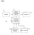
- a calibrating apparatus 10 includes a camera 12 that repeatedly outputs image data representing a scene captured on an imaging surface.
- the image data outputted from the camera 12 is taken by an image processing circuit 14, and subjected to a camera-image display process by a CPU 14p.
- a CPU 14p a CPU 14p.
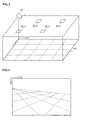
- the camera 12 is installed at an upper portion on a wall surface of a room having a plane FS 1, and captures the plane FS 1 from a diagonally upper position. Therefore, the camera image is displayed on a monitor screen as shown in Figure 4 .
- the plane FS 1 is defined by an X axis and a Y axis orthogonal to each other, and the camera image is reproduced along a U axis and a V axis orthogonal to each other.
- air conditioning devices AC_1 to AC_4 are installed at a predetermined distance. Each of the air conditioning devices AC_1 to AC_4 outputs air at a designated temperature in a designated air amount. A room temperature is adjusted by the air thus outputted
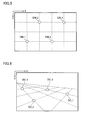
- a parameter calculation-use map image is displayed on the monitor 16 as shown in Figure 5 .
- the map image is equivalent to an image schematically representing a state in which the plane FS 1 is outlined or overlooked.
- an X-Y coordinates designating manipulation of designating desired X-Y coordinates on the displayed map image is accepted from a manipulator through the input device 18.
- a variable K is updated from “1" to "4" at each X-Y coordinates designating manipulation.
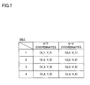
- X-Y coordinates (X_K, Y_K) designated by a K-th X-Y coordinates designating manipulation are set to a K-th column of a register 14r1 shown in Figure 7 .
- a dot DM_K is displayed on the map image.
- Four X-Y coordinates (X_1, Y_1) to (X_4, Y_4) are set to the register 14r1, and corresponding dots DM_1 to DM_4 are displayed on the map image as shown in Figure 5 , for example.
- U-V coordinates designating manipulation of clicking desired U-V coordinates on the camera image is accepted from the manipulator through the input device 18.
- a variable K is updated from "1" to "4" at each U-V coordinates designating manipulation.
- U-V coordinates (U_K, V_K) designated by a K-th U-V coordinates designating manipulation are set to a K-th column of the register 14r1 shown in Figure 7 .
- the dot DC_K is displayed on the camera image.
- U-V coordinates designating manipulations are accepted.
- the designated four U-V coordinates (U_1, V_1) to (U_4, V_4) are set to the register 14r1, and the corresponding dots DC_1 to DC_4 are displayed on the camera image as shown in Figure 6 , for example.
- Equation 1 the mutually corresponding X-Y coordinates (X_K, Y_K) and U-V coordinates (U_K, V_K) are applied to Equation 1, and thereby, eight transformation equations (four equations for the U coordinate and four equations for the V coordinate) are produced.
- the calibration parameters P11 to P33 are calculated by solving simultaneous equations derived from the produced eight transformation equations.
- an area setting-use map image is displayed on the monitor 16 as shown in Figure 8 .
- the map image also is equivalent to the image schematically representing a state in which the plane FS 1 is outlined or overlooked.
- marks Mac1 to Mac4 respectively representing the air conditioning devices AC_1 to AC_4 are displayed corresponding to the positions of the air conditioning devices AC_1 to AC_4.
- the number of already-set air conditioning areas is set to the variable K. It is noted that if none of the air conditioning areas is set, a value of the variable K is set to "0".
- variable K is incremented, and a line indicating the designated rectangular area is drawn on the map image.
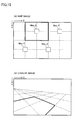
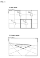
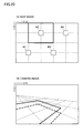
- the line indicating the rectangular area is drawn as shown in Figure 10(A) when a drag manipulation is performed to surround the mark Mac2, and drawn as shown in Figure 11 (A) when the drag manipulation is performed to surround the mark Mac3.
- the four X-Y coordinates (X_1, Y_1), (X_2, Y_2), (X_3, Y_3), and (X_4, Y_4) respectively corresponding to four corners of the designated rectangular area are set to a register 14r2 shown in Figure 9 corresponding to the value of the variable K.
- the X-Y coordinates (X_1, Y_1) are described in a first column that corresponds to the variable K, and the X-Y coordinates (X_2, Y_2) are described in a second column that corresponds to the variable K.
- the X-Y coordinates (X_3, Y_3) are described in a third column that corresponds to the variable K
- the X-Y coordinates (X_4, Y_4) are described in a fourth column that corresponds to the variable K.
- variable L Upon completion of the process of setting to the register 14r2, the variable L is set to each of"1"to "4".
- X-Y coordinates (X_L, Y_L) described in an L-th column that corresponds to the variable K are transformed into U-V coordinates (U_L, V_L) according to Equation 1.
- the calibration parameters P11 to P33 are equivalent to a matrix for performing a planar projective transformation between the X-Y coordinate system defining the plane FS 1 and the U-V coordinate system defining the camera image. Therefore, when the X-Y coordinates (X_L, Y_L) on the plane FS1 are applied to Equation 1, the corresponding U-V coordinates (U_L, V_L) on the camera image are calculated.
- the U-V coordinates (U_L, V_L) thus transformed are described in the register 14r2 corresponding to the X-Y coordinates (X_L, Y_L), which are a transformation source.
- a total of four transformation processes according to Equation 1 are executed, and as a result, the U-V coordinates (U_1, V_1), (U_2, V_2), (U_3, V_3), and (U_4, V_4) respectively corresponding to the X-Y coordinates (X_1, Y_1), (X_2, Y_2), (X_3, Y_3), and (X_4, Y_4) are calculated.
- an area surrounded by the U-V coordinates (U_1, V_1), (U_2, V_2), (U_3, V_3), and (U_4, V_4) is specified as the air conditioning area, and the line indicating the specified air conditioning area is drawn on the camera image.
- the line defining the air conditioning area is drawn as shown in Figure 10(B) corresponding to the rectangular area shown in Figure 10(A) , and drawn as shown in Figure 11 (B) corresponding to the rectangular area shown in Figure 11(A) .
- the CPU 14p adjusts outputs of air conditioning devices D_1 to D_4 by referring to a disposition of the air conditioning areas set to the register 142r and a movement of an object appearing in the camera image.
- Such air conditioning control is executed at each arrival of an adjustment cycle.
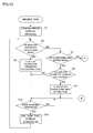
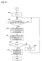
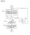
- the CPU 14p executes a plurality of tasks including an imaging task shown in Figure 13 and Figure 14 , a calibration parameter calculating task shown in Figure 15 and Figure 16 , an air conditioning area setting task shown in Figure 17 and Figure 18 , and an air conditioning control task shown in Figure 19 . It is noted that control programs corresponding to these tasks are saved in a recording medium 20.
- a camera-image display process is executed in a step S 1.
- the camera image is displayed on the monitor 16. It is determined in a step S3 whether or not an operation mode at a current time point is the calibration parameter calculating mode, it is determined in a step S7 whether or not the operation mode at a current time point is the air conditioning area setting mode, and it is determined in a step S 17 whether or not the operation mode at a current time point is the air conditioning control mode.
- the calibration parameter calculating task is started in a step S5, and thereafter, the process advances to a step S 13.
- YES is determined in the step S7, it is determined in a step S9 whether or not the calibration parameter is already calculated.
- the process advances to the step S 13 after starting the air conditioning area setting task in a step S 11, and when the determined result is NO, the process directly advances to the step S 13.
- step S 17 When YES is determined in the step S 17, it is determined in a step S 19 whether or not the air conditioning area is already set When a determined result is YES, the process advances to the step S13 after starting the air conditioning control task in a step S21, and when the determined result is NO, the process directly advances to the step S 13. When NO is determined in all of the steps S3, S7, and S 17, the process advances to the step S 13 after executing another process in a step S23.
- step S 13 it is repeatedly determined whether or not a mode changing manipulation is performed.
- a determined result is updated from NO to YES
- the task that is being started is ended in a step S15. Thereafter, the process returns to the step S3.
- the parameter calculation-use map image is displayed on the monitor 16 in a step S31, and the variable K is set to "1" in a step S33.
- a step S35 it is determined whether or not the X-Y coordinates designating manipulation is performed.
- the process advances to a step S37 so as to set the X-Y coordinates (X_K, Y_K) designated by the X-Y coordinates designating manipulation to the K-th column of the register 14r1.
- a marker DM_K is displayed on the map image.
- a step S41 it is determined whether or not the variable K reaches "4", and when a determined result is NO, the process returns to the step S35 after incrementing the variable K in a step S43 while when the determined result is YES, the process advances to a step S45.
- the variable K is set to "1", and it is repeatedly determined in a step S47 whether or not the U-V coordinates designating manipulation is performed
- the process advances to a step S49 so as to set the designated U-V coordinates (U_K, V_K) to the K-th column of the register 14r1.
- the marker DC_K is displayed on the camera image.
- a step S53 it is determined whether or not the variable K reaches "4".
- the variable K is incremented in a step S55, and then, the process returns to the step S47 while the determined result is YES, the process advances to a step S57.
- the X-Y coordinates (X_1, Y_1) to (X_4, Y_4) and the U-V coordinates (U_1, V_1) to (U_4, V_4) set to the register 14r1 are applied to the above-described Equation 1 so as to calculate the calibration parameters P11 to P33.
- the area setting-use map image is displayed on the monitor 16 in a step S61, and the value of the variable K is set in a step S63. If none of the air conditioning areas is set, then the value of the variable K is set to "0". On the other hand, if one or at least two air conditioning areas are already set, then the value of the variable K is set to the number of the set air conditioning areas.
- a step S65 it is determined whether or not the drag manipulation for the area designation is performed, and when a determined result is updated from NO to YES, the variable K is incremented in a step S67.
- a step S69 the line defining the rectangular area designated by the drag manipulation is drawn on the map image.
- a step S71 the four X-Y coordinates (X_1, Y_1), (X_2, Y_2), (X_3, Y_3), and (X_4, Y_4) respectively corresponding to the four corners of the rectangular area thus designated are specified.
- the specified X-Y coordinates (X_1, Y_1), (X_2, Y_2), (X_3, Y_3), and (X_4, Y_4) are set to the register 14r2, corresponding to the value of the variable K.
- the variable L is set to "1" in a step S73.
- the X-Y coordinates (X_L, Y_L) described in the L-th column corresponding to the variable K are read out from the register 14r2, and the read-out X-Y coordinates (X_L, Y_L) are transformed into the U-V coordinates (U_L, V_L) according to Equation 1.
- the transformed U-V coordinates (U_L, V_L) are described in the register 14r2 corresponding to the X-Y coordinates (X_L, Y_L), which are a transformation source.
- a step S77 it is determined whether or not the variable L reaches "4".
- a determined result is NO
- the variable L is incremented in a step S79, and then, the process returns to the step S75.
- the process advances to a step S81. Therefore, processes after the step S81 are executed after the X-Y coordinates (X_1, Y_1), (X_2, Y_2), (X_3, Y_3), and (X_4, Y_4) are transformed into the U-V coordinates (U_1, V_1), (U_2, V_2), (U_3, Y_3), and (U_4, V_4).
- step S81 the area surrounded by the U-V coordinates (U_1, V_1), (U_2, V_2), (U_3, V_3), and (U_4, V_4) that correspond to the variable K is specified as the air conditioning area.
- step S83 the line defining the specified air conditioning area is drawn on the camera image. When the line is drawn, the process returns to the step S65, regarding that the setting for the K-th air conditioning area is completed.
- the disposition of the air conditioning areas set to the register 142r is detected in a step S91, and it is determined in a step S93 whether or not the adjustment cycle is arrived.
- the process advances to a step S95 so as to detect the movement of the object based on the camera image.
- the variable N is set to "1”
- the output of the air conditioning device AC_N is adjusted by referring to the disposition detected in the step S91 and the movement detected in the step S95.
- a step S101 it is determined whether or not the variable N reaches "4".
- the process returns to the step S99 after incrementing the variable N in a step S 103 while when the determined result is YES, the process directly returns to the step S93.
- the CPU 14p displays on the monitor 16 the map image representing the state in which the plane FS 1 is outlined or overlooked along the X axis and the Y axis orthogonal to each other (S61), and displays on the monitor 16 the camera image outputted from the camera 12 that captures the plane FS 1 from an upper diagonal position along the U axis and the V axis orthogonal each other (S1).
- the CPU 14p accepts the drag manipulation of designating the rectangular area of the X-Y coordinate system on the area setting-use map image displayed on the monitor 16 (S65), calculates the air conditioning area of the U-V coordinate system that corresponds to the designated rectangular area by referring to the calibration parameter indicating the corresponding relationship between the X-Y coordinate system and the U-V coordinate system (S67 to S81), and defines the calculated air conditioning area on the camera image displayed on the monitor 16 (S83).
- the map image is displayed along the X axis and the Y axis while the camera image is displayed along the U axis and the V axis, and the corresponding relationship between the X-Y coordinate system and the U-V coordinate system is shown by the calibration parameter.
- the rectangular area of the X-Y coordinate system is designated in association with the process of displaying the map image
- the air conditioning area of the U-V coordinate system that corresponds to the designated rectangular area is defined on the camera image.
- the manipulability regarding the area setting is improved.
- the air conditioning area corresponding to the rectangular area on the camera image, it becomes easier to determine whether or not the area setting is appropriate. Thus, a load imposed on an area setting task is reduced.
- the rectangular area is designated by the drag manipulation of the mouse pointer.
- the rectangular area may be designated by a manipulation of clicking the mouse pointer or direct input of a numerical value indicating the U-V coordinates.
- the rectangular area is formed by linking the proximal U-V coordinates by straight lines.
- the area defined on the map image is rectangular, and the position of and the expansion of the rectangular area are set according to the drag manipulation.
- the shape, the position, and the expansion of the area defined on the map image may also be set in consideration of the positions and an output capability of the air conditioning devices AC_1 to AC_4.
- the air conditioning device influencing the coordinates designated by the click manipulation is specified by a weighting calculation in which the distance from the designated coordinates to the air conditioning devices AC to AC 4 and the output capability of the air conditioning devices AC_1 to AC_4 are referenced, and the area having the shape and the expansion corresponding to the output capability of the specified air conditioning device is set to a position where the specified air conditioning device is centered.
- the plane FS1 is captured from a diagonally upper position by the camera 12 installed at the upper portion on the wall surface, however, instead thereof, the plane FS 1 may be captured from directly above by an omnidirectional camera set on a ceiling.
- the calibration parameter is calculated based on the four U-V coordinates and the four X-Y coordinates, however, the number of coordinates to be referred to in order to calculate the calibration parameter may be "5" or more.
- the output of the air conditioning device is adaptively controlled, however, instead of the output of the air conditioning device, or together with the output of the air conditioning device, the output of an illuminating device (i.e., brightness) may be adaptively controlled.
- planar projective transformation is performed between the X-Y coordinate system defining the plane FS 1 and the U-V coordinate system defining the camera image.
- the calibration parameters P11 to P33 applied to Equation 1 are adjusted to values in which an offset equivalent to a height of the desk (an offset in a length direction of a Z axis orthogonal to an X axis and a Y axis) is taken into consideration. If the planar projective transformation is executed by referring to the calibration parameters P11 to P33 having the thus adjusted values, then a measurement area corresponding to a rectangular area indicated by a bold line in Figure 20(A) is set as indicated by a bold line in Figure 20 (B) (a dotted line indicates a previous setting).
- a pole capable of adjusting a height as shown in Figure 21 , be placed on a floor surface, and desired U-V coordinates be designated by clicking the pole appearing in a camera image.
- a position of X-Y coordinates of each air conditioner is previously registered as a default value, a task of designating the U-V coordinates is performed by sequentially placing an index (marker) such as the pole, etc., at each position, and then, the calibration parameter is calculated. In this way, the task of designating the X-Y coordinates in the process of calculating the calibration parameter becomes unnecessary.
- the air conditioner is fixed, and thus, the position at which the index is placed is directly below the air conditioner and is easy to determine. As a result, it is possible to reduce a burden of a task of designating the position of the X-Y coordinates obtained when the calibration parameter is calculated at each calibration and the position of the U-V coordinates corresponding thereto.
Landscapes
- Engineering & Computer Science (AREA)
- Computer Vision & Pattern Recognition (AREA)
- Physics & Mathematics (AREA)
- General Physics & Mathematics (AREA)
- Theoretical Computer Science (AREA)
- Image Processing (AREA)
- Air Conditioning Control Device (AREA)
- Image Analysis (AREA)
Applications Claiming Priority (1)
| Application Number | Priority Date | Filing Date | Title |
|---|---|---|---|
| JP2010014423A JP2011153737A (ja) | 2010-01-26 | 2010-01-26 | 校正装置 |
Publications (1)
| Publication Number | Publication Date |
|---|---|
| EP2362349A2 true EP2362349A2 (de) | 2011-08-31 |
Family
ID=44227789
Family Applications (1)
| Application Number | Title | Priority Date | Filing Date |
|---|---|---|---|
| EP11000505A Withdrawn EP2362349A2 (de) | 2010-01-26 | 2011-01-21 | Kalibriervorrichtung |
Country Status (4)
| Country | Link |
|---|---|
| US (1) | US8411999B2 (de) |
| EP (1) | EP2362349A2 (de) |
| JP (1) | JP2011153737A (de) |
| CN (1) | CN102136149A (de) |
Families Citing this family (8)
| Publication number | Priority date | Publication date | Assignee | Title |
|---|---|---|---|---|
| JP2011154448A (ja) * | 2010-01-26 | 2011-08-11 | Sanyo Electric Co Ltd | 校正パラメータ作成装置 |
| CN103425626B (zh) * | 2012-05-22 | 2016-08-31 | 杭州普维光电技术有限公司 | 一种摄像机间坐标转换方法及装置 |
| JP5879220B2 (ja) * | 2012-07-06 | 2016-03-08 | 日立アプライアンス株式会社 | 空気調和機 |
| US9987184B2 (en) * | 2013-02-05 | 2018-06-05 | Valentin Borovinov | Systems, methods, and media for providing video of a burial memorial |
| CN106885555B (zh) * | 2016-12-26 | 2019-02-01 | 中国科学院长春光学精密机械与物理研究所 | 远紫外成像仪光学系统坐标系标定方法 |
| WO2021117236A1 (ja) * | 2019-12-13 | 2021-06-17 | 三菱電機株式会社 | 空調制御システム、空調システム及び関連付け方法 |
| EP3968283A1 (de) * | 2020-09-14 | 2022-03-16 | Eppendorf AG | Verfahren zum kalibrieren einer optischen aufzeichnungsvorrichtung |
| CN118242991B (zh) * | 2024-05-21 | 2024-07-26 | 中山大学 | 基于单一影像和空调外机神经网络的建筑物测量方法 |
Citations (1)
| Publication number | Priority date | Publication date | Assignee | Title |
|---|---|---|---|---|
| JP2010014423A (ja) | 2008-07-01 | 2010-01-21 | Yokogawa Electric Corp | 半導体試験装置 |
Family Cites Families (8)
| Publication number | Priority date | Publication date | Assignee | Title |
|---|---|---|---|---|
| GB0305315D0 (en) * | 2003-03-07 | 2003-04-09 | Weber Martin | Image processing system |
| JP4307934B2 (ja) * | 2003-08-13 | 2009-08-05 | 株式会社トプコン | 画像補正機能付撮影装置及び方法、並びに撮影装置及び方法 |
| JP4681856B2 (ja) * | 2004-11-24 | 2011-05-11 | アイシン精機株式会社 | カメラの校正方法及びカメラの校正装置 |
| US7974461B2 (en) * | 2005-02-11 | 2011-07-05 | Deltasphere, Inc. | Method and apparatus for displaying a calculated geometric entity within one or more 3D rangefinder data sets |
| US7583815B2 (en) * | 2005-04-05 | 2009-09-01 | Objectvideo Inc. | Wide-area site-based video surveillance system |
| EP1882895A4 (de) * | 2005-05-12 | 2012-06-27 | Techno Dream 21 Co Ltd | Messverfahren für dreidimensionales formen und einrichtung dafür |
| JP4966820B2 (ja) | 2007-10-29 | 2012-07-04 | パナソニック株式会社 | 混雑推定装置および方法 |
| JP5079547B2 (ja) * | 2008-03-03 | 2012-11-21 | Toa株式会社 | カメラキャリブレーション装置およびカメラキャリブレーション方法 |
-
2010
- 2010-01-26 JP JP2010014423A patent/JP2011153737A/ja not_active Withdrawn
-
2011
- 2011-01-20 CN CN2011100252352A patent/CN102136149A/zh active Pending
- 2011-01-21 EP EP11000505A patent/EP2362349A2/de not_active Withdrawn
- 2011-01-25 US US13/013,766 patent/US8411999B2/en not_active Expired - Fee Related
Patent Citations (1)
| Publication number | Priority date | Publication date | Assignee | Title |
|---|---|---|---|---|
| JP2010014423A (ja) | 2008-07-01 | 2010-01-21 | Yokogawa Electric Corp | 半導体試験装置 |
Also Published As
| Publication number | Publication date |
|---|---|
| CN102136149A (zh) | 2011-07-27 |
| JP2011153737A (ja) | 2011-08-11 |
| US8411999B2 (en) | 2013-04-02 |
| US20110181733A1 (en) | 2011-07-28 |
Similar Documents
| Publication | Publication Date | Title |
|---|---|---|
| US8411999B2 (en) | Calibrating apparatus | |
| JP5566281B2 (ja) | 旋回型カメラの設置条件特定装置および方法ならびに当該設置条件特定装置を備えるカメラ制御システム | |
| US9441850B2 (en) | Air-conditioning management apparatus | |
| JP6310149B2 (ja) | 画像生成装置、画像生成システム及び画像生成方法 | |
| JP2017129992A (ja) | 情報処理装置およびその制御方法 | |
| JP2010119314A (ja) | 細胞画像解析装置 | |
| CN111339588A (zh) | 一种二维图纸与三维模型检查方法、系统及存储介质 | |
| US7227549B2 (en) | Indicating and manipulating a zoom region of a waveform | |
| CN114897965B (zh) | 一种三维场景开敞度分析的方法及系统 | |
| WO2012011400A1 (ja) | 出力制御装置 | |
| CN119369416B (zh) | 标定方法、标定装置及计算机可读存储介质 | |
| JP3887758B2 (ja) | グラフィカルユーザインタフェース装置及びグラフィカルユーザインタフェース画面作成方法 | |
| CN113253622B (zh) | 基于HomeMap的网络环境视觉化控制方法及系统 | |
| JPH06195472A (ja) | 画像処理システム | |
| EP2362352A2 (de) | Vorrichtung zur Messung des Überlastungsgrades | |
| US5302967A (en) | Figure processing apparatus and method aided by display with ruled lines | |
| EP2449340B1 (de) | Fahrzeugmessungssystem mit benutzerschnittstelle | |
| CN113253623B (zh) | 基于HomeMap的空气环境视觉化控制方法及系统 | |
| JP3361652B2 (ja) | 立体図形配置入力方法及びグラフィックシステム | |
| TW202032448A (zh) | 專利文件的圖形自動顯示裝置 | |
| CN115859014A (zh) | 绝对定位精度的预测方法、装置、设备及存储介质 | |
| JPH08314997A (ja) | 多次元形状の座標計測システム及び測定情報の教示方法 | |
| JP4490215B2 (ja) | データ表示装置及びプログラム | |
| JP6293293B2 (ja) | マルチセンサ計測装置のルーティンを確立する方法 | |
| JP2004118734A (ja) | 情報処理方法及び情報処理装置 |
Legal Events
| Date | Code | Title | Description |
|---|---|---|---|
| PUAI | Public reference made under article 153(3) epc to a published international application that has entered the european phase |
Free format text: ORIGINAL CODE: 0009012 |
|
| AK | Designated contracting states |
Kind code of ref document: A2 Designated state(s): AL AT BE BG CH CY CZ DE DK EE ES FI FR GB GR HR HU IE IS IT LI LT LU LV MC MK MT NL NO PL PT RO RS SE SI SK SM TR |
|
| AX | Request for extension of the european patent |
Extension state: BA ME |
|
| STAA | Information on the status of an ep patent application or granted ep patent |
Free format text: STATUS: THE APPLICATION HAS BEEN WITHDRAWN |
|
| 18W | Application withdrawn |
Effective date: 20140123 |