EP2362094A2 - Method and device for attaching a reference marking to a rotor blade of a wind turbine - Google Patents
Method and device for attaching a reference marking to a rotor blade of a wind turbine Download PDFInfo
- Publication number
- EP2362094A2 EP2362094A2 EP11152225A EP11152225A EP2362094A2 EP 2362094 A2 EP2362094 A2 EP 2362094A2 EP 11152225 A EP11152225 A EP 11152225A EP 11152225 A EP11152225 A EP 11152225A EP 2362094 A2 EP2362094 A2 EP 2362094A2
- Authority
- EP
- European Patent Office
- Prior art keywords
- rotor blade
- marking
- holding device
- blade
- mold
- Prior art date
- Legal status (The legal status is an assumption and is not a legal conclusion. Google has not performed a legal analysis and makes no representation as to the accuracy of the status listed.)
- Granted
Links
Images


Classifications
-
- B—PERFORMING OPERATIONS; TRANSPORTING
- B23—MACHINE TOOLS; METAL-WORKING NOT OTHERWISE PROVIDED FOR
- B23B—TURNING; BORING
- B23B47/00—Constructional features of components specially designed for boring or drilling machines; Accessories therefor
- B23B47/28—Drill jigs for workpieces
-
- F—MECHANICAL ENGINEERING; LIGHTING; HEATING; WEAPONS; BLASTING
- F03—MACHINES OR ENGINES FOR LIQUIDS; WIND, SPRING, OR WEIGHT MOTORS; PRODUCING MECHANICAL POWER OR A REACTIVE PROPULSIVE THRUST, NOT OTHERWISE PROVIDED FOR
- F03D—WIND MOTORS
- F03D13/00—Assembly, mounting or commissioning of wind motors; Arrangements specially adapted for transporting wind motor components
- F03D13/10—Assembly of wind motors; Arrangements for erecting wind motors
-
- F—MECHANICAL ENGINEERING; LIGHTING; HEATING; WEAPONS; BLASTING
- F03—MACHINES OR ENGINES FOR LIQUIDS; WIND, SPRING, OR WEIGHT MOTORS; PRODUCING MECHANICAL POWER OR A REACTIVE PROPULSIVE THRUST, NOT OTHERWISE PROVIDED FOR
- F03D—WIND MOTORS
- F03D80/00—Details, components or accessories not provided for in groups F03D1/00 - F03D17/00
-
- B—PERFORMING OPERATIONS; TRANSPORTING
- B23—MACHINE TOOLS; METAL-WORKING NOT OTHERWISE PROVIDED FOR
- B23B—TURNING; BORING
- B23B2247/00—Details of drilling jigs
- B23B2247/12—Drilling jigs with means to affix the jig to the workpiece
-
- B—PERFORMING OPERATIONS; TRANSPORTING
- B29—WORKING OF PLASTICS; WORKING OF SUBSTANCES IN A PLASTIC STATE IN GENERAL
- B29C—SHAPING OR JOINING OF PLASTICS; SHAPING OF MATERIAL IN A PLASTIC STATE, NOT OTHERWISE PROVIDED FOR; AFTER-TREATMENT OF THE SHAPED PRODUCTS, e.g. REPAIRING
- B29C59/00—Surface shaping of articles, e.g. embossing; Apparatus therefor
- B29C59/02—Surface shaping of articles, e.g. embossing; Apparatus therefor by mechanical means, e.g. pressing
-
- B—PERFORMING OPERATIONS; TRANSPORTING
- B29—WORKING OF PLASTICS; WORKING OF SUBSTANCES IN A PLASTIC STATE IN GENERAL
- B29L—INDEXING SCHEME ASSOCIATED WITH SUBCLASS B29C, RELATING TO PARTICULAR ARTICLES
- B29L2031/00—Other particular articles
- B29L2031/08—Blades for rotors, stators, fans, turbines or the like, e.g. screw propellers
- B29L2031/082—Blades, e.g. for helicopters
- B29L2031/085—Wind turbine blades
-
- F—MECHANICAL ENGINEERING; LIGHTING; HEATING; WEAPONS; BLASTING
- F05—INDEXING SCHEMES RELATING TO ENGINES OR PUMPS IN VARIOUS SUBCLASSES OF CLASSES F01-F04
- F05B—INDEXING SCHEME RELATING TO WIND, SPRING, WEIGHT, INERTIA OR LIKE MOTORS, TO MACHINES OR ENGINES FOR LIQUIDS COVERED BY SUBCLASSES F03B, F03D AND F03G
- F05B2260/00—Function
- F05B2260/80—Diagnostics
-
- F—MECHANICAL ENGINEERING; LIGHTING; HEATING; WEAPONS; BLASTING
- F05—INDEXING SCHEMES RELATING TO ENGINES OR PUMPS IN VARIOUS SUBCLASSES OF CLASSES F01-F04
- F05B—INDEXING SCHEME RELATING TO WIND, SPRING, WEIGHT, INERTIA OR LIKE MOTORS, TO MACHINES OR ENGINES FOR LIQUIDS COVERED BY SUBCLASSES F03B, F03D AND F03G
- F05B2260/00—Function
- F05B2260/83—Testing, e.g. methods, components or tools therefor
-
- Y—GENERAL TAGGING OF NEW TECHNOLOGICAL DEVELOPMENTS; GENERAL TAGGING OF CROSS-SECTIONAL TECHNOLOGIES SPANNING OVER SEVERAL SECTIONS OF THE IPC; TECHNICAL SUBJECTS COVERED BY FORMER USPC CROSS-REFERENCE ART COLLECTIONS [XRACs] AND DIGESTS
- Y02—TECHNOLOGIES OR APPLICATIONS FOR MITIGATION OR ADAPTATION AGAINST CLIMATE CHANGE
- Y02E—REDUCTION OF GREENHOUSE GAS [GHG] EMISSIONS, RELATED TO ENERGY GENERATION, TRANSMISSION OR DISTRIBUTION
- Y02E10/00—Energy generation through renewable energy sources
- Y02E10/70—Wind energy
- Y02E10/72—Wind turbines with rotation axis in wind direction
-
- Y—GENERAL TAGGING OF NEW TECHNOLOGICAL DEVELOPMENTS; GENERAL TAGGING OF CROSS-SECTIONAL TECHNOLOGIES SPANNING OVER SEVERAL SECTIONS OF THE IPC; TECHNICAL SUBJECTS COVERED BY FORMER USPC CROSS-REFERENCE ART COLLECTIONS [XRACs] AND DIGESTS
- Y02—TECHNOLOGIES OR APPLICATIONS FOR MITIGATION OR ADAPTATION AGAINST CLIMATE CHANGE
- Y02P—CLIMATE CHANGE MITIGATION TECHNOLOGIES IN THE PRODUCTION OR PROCESSING OF GOODS
- Y02P70/00—Climate change mitigation technologies in the production process for final industrial or consumer products
- Y02P70/50—Manufacturing or production processes characterised by the final manufactured product
Definitions
- the invention relates to a method, a device and an arrangement for attaching a reference marking on a rotor blade for a wind energy plant and a use.
- the rotor blades of the wind turbine When operating wind turbines, imbalances caused by different settings of the rotor blade angles of the rotor blades of a rotor lead to a reduction of the achievable energy yield. At the same time, they endanger the integrity of wind turbines. When erecting and operating wind turbines, it must therefore be ensured that the rotor blades of the wind turbine are operated at identical and predetermined setting angles.
- the rotor blades usually have reference marks, also called 0 ° marks or zero marks, which are aligned with marks on the central rotor hub.
- U1 discloses a device for aligning an angle-adjustable rotor blade of a wind turbine, which has at least two reference points, which can be arranged in the interior of the rotor blade in a predetermined position to the rotor blade.
- the device comprises a measuring device with which the position of the reference points relative to a reference system can be measured.
- the arrangement of the reference points in the interior of the rotor blade a safe, accurate and largely weather-independent and time-saving possibility for measuring the Rotorblatteinstellwinkel is created.
- a common method for attaching corresponding reference markers provides that a profile template is pushed from the outside over a rotor blade on the fully assembled wind turbine, which then by means of optical methods with respect to a Reference plane, for example, the rotor plane or the rotor axis plane, is measured.
- a Reference plane for example, the rotor plane or the rotor axis plane
- rotor blades with reference markings already after their production, before they are mounted on a wind turbine.
- the position is measured for a zero mark, wherein the separation plane of the rotor blade, i. the level which separates an upper half-shell from a lower half-shell of the rotor blade, is assumed.
- the half-shells are usually made of a laminated with a resin material composite of several layers of glass and / or carbon fiber mats.
- the methods described above do not allow the required accuracy of 0.3 °, preferably 0.1 °, since the inclination of the rotor blade in the power range is decisive for the zero angle to be marked on the blade root, ie the outer region arranged towards the tip of the rotor blade , which provides the largest power contribution to the rotor blade. Accordingly, the 0 ° angle with respect to the leading edge of the rotor blade profile in the power range defined, in contrast, the leading edge of the rotor blade profile is rotated at the blade root by a certain angle. The zero mark is therefore generally inconsistent with the leading edge position of the blade root.
- the rotor blade is very flexible and bends under its own weight. If the profile or the leading edge of the profile is placed vertically in the power range, it is not ensured that the blade root-side range is in a position that can be reproduced at 0.1 ° to 0.3 ° or in an angular position. Due to individual stresses and distortions of each rotor blade occurs a variation of the angular ratios and thus the reference marking points, which is above the desired accuracy range.
- the present invention has the object to be able to attach reference marks on a rotor blade for a wind turbine reproducible and with high accuracy.
- This object is achieved by a method for attaching a reference mark on a rotor blade for a wind turbine, wherein after the manufacture of the rotor blade in a manufacturing mold and before the detachment of the rotor blade from the manufacturing mold by means of a marking device, which with a at a predetermined or predeterminable position the manufacturing form arranged holding device is connectable or connected, a reference mark in the region of a rotor blade root of the rotor blade is mounted.
- the method according to the invention has the advantage that the reference marking is inserted in a production step in which the rotor blade is still in its production form, so that its position over the entire length of the rotor blade is very well defined.
- the marking is introduced by means of a tool which is firmly connected to the mold and thus also assumes a well-defined position relative to the rotor blade in its entire length. The inaccuracy causing influence of the flexibility of the rotor blade material is suppressed.
- the marking device is connected to the holding device after the manufacture of the rotor blade in the production form.
- this approach has the advantage that the marking device does not interfere or interfere with the injection of resin into the mold. This promotes complete integrity of the rotor blade material at its blade root end.
- the reference mark is attached to an inner side of the rotor blade. This creates a, in particular weather-independent and time-saving, possibility for measuring rotor blade pitch angles, which brings particular advantages in particular for offshore wind turbines which are exposed to harsh climatic conditions.
- a preferred way of attaching a reference mark is to create the reference mark by drilling through a drilling template of the marking device.
- a hole that penetrates no more than 5 mm (millimeters) deep into the material of the rotor blade is easily visible and easy to measure, without affecting the laminated material and thus the structural strength of the rotor blade.
- the object underlying the invention is also by a
- a device for mounting a reference mark on a rotor blade for a wind turbine comprising a holding device and a marking device with a marking element, wherein the holding device is formed with a manufacturing mold for a rotor blade in a predetermined or predeterminable position in a region of a blade root-side end of the rotor blade connectable or connected, wherein the marking device is designed to be connectable or connected to the holding device.
- the device according to the invention has the advantage already mentioned for the method according to the invention that a holding device for the marking device is arranged at a predetermined or predeterminable position on the production mold and a marking device is connected to the holding device.
- the marking element receives via the marking device and the holding device a predetermined and reproducible position with respect to the manufacturing mold for the rotor blade and each manufactured and arranged in the form rotor blade, including with respect to the power range whose orientation is relevant for the zero mark.
- the marking element advantageously comprises a drill or a color applicator, for example a print head, a paint brush or a pen.
- the marking element comprises a drilling template.
- a drilling template is understood in the context of the invention as a guide body with a central through hole for a drill, which can be attached by means of the drilling template in a fixed and predetermined position.
- the marking element is in a radial
- the radial direction is defined in the context of the invention over the usual shape of the rotor blade root end of a rotor blade, which is usually circular.
- the radial direction is a direction toward the center of this circle toward or away from the center point of the circle. Such a movement does not change the angular position of the marking element.
- the radial mobility causes the marking element to be adapted to different thicknesses of rotor blades in the blade root-side region of the rotor blade, or that, for example, a drill or a color applicator can be approximated to the surface of the rotor blade.
- the marking element is arranged on an inner surface of a rotor blade in the production mold when the marking device is connected to the holding device. Such arranged markings are largely protected from the weather and therefore very durable.
- the object underlying the invention is further achieved by an arrangement for attaching a reference mark on a rotor blade for a wind turbine, comprising a manufacturing mold for a rotor blade and a device according to the invention described above, wherein the holding device with the manufacturing mold in a predetermined or predeterminable position in a region of a blade root-side end of the rotor blade is connectable or connected to the manufacturing mold.
- This arrangement has the advantages according to the invention described above.
- a part of the production form is designed as a holding device.
- the holding device is detachably connected to the production mold.
- the object underlying the invention is also achieved by using a device with a holding device and a marking device, in particular an inventive device described above, for attaching a reference mark on a rotor blade for a wind turbine, which is characterized in that the holding device and the Marking device when attaching the reference mark on the rotor blade at a predetermined or predeterminable position at a blade root end of a manufacturing mold for the rotor blade is arranged.
- FIG. 1 With reference to a known method for applying a reference mark or zero marking, a perspective view of the blade root-side end of a rotor blade 1 is shown schematically.
- the rotor blade root 5 carries a circular blade connection sleeve 7. Perspectively behind it in the image, the power range of the rotor blade 1 is shown, which ends in the rotor blade tip 6.
- the rotor blade is set so that the power range is vertical.
- two profile templates 2 are pushed onto two different positions in the power range of the rotor blade 1, each with an inclinometer 3 or tilt sensor 3 are equipped. Based on their display, it is determined when the power range of the rotor blade 1 is vertical.
- a 0 ° device 4 is arranged for attaching a zero mark in the region of the blade root.
- the 0 ° device comprises an arm whose length corresponds to the diameter of the rotor blade root 5, and a second arm, which is half as long and is articulated in the center of the rotor blade root 5 on the first arm.
- the first arm is oriented to the orientation of the rotor blade 1 in the region of the blade root 5 and is at an angle to the power range.
- the shorter second arm is equipped with an inclinometer 3 and is used for measuring the zero angle or a zero mark.
- a blade root-side end of a rotor blade is shown schematically. This comprises two half shells of a trailing edge 8 and a leading edge 9 of the rotor blade, which collide at a common abutting edge 10. To create a 0 ° mark, a setting template 12 is placed on the blade connection sleeve 7.
- the setting template 12 comprises a reference pin 13 and a viewing window 14, are visible through the bolt 11 of the blade connection sleeve 7. Below and above the rotor blade has the Set stencil mark 15, between which a zero mark can be placed.
- the blade connection sleeve 7 on the blade root end of the shells is not quite accurate and reproducible attachable, so that is also not guaranteed that the bolts 11 of the blade connection sleeve 7, for example, always take the same relative positions with respect to the abutting edge 10. This leads to another source of inaccuracies in applying marker positions.
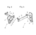
- a device according to the invention for attaching reference marks in rotor blades is shown schematically.
- the device 20 comprises a holding device 21 and a marking device 23.
- the marking device 23 comprises in Fig. 3 a drilling template 24 which is arranged on a support arm 25, which in turn is connected to a spacer 26.
- the spacer 26 is fastened by means of screws through slots 27 on the holding device 21 and in Fig. 3 attached.
- the support arm 25 is also secured via slots 27 to the spacer 26.
- the long holes 27 are oriented so that a variation of the position of the screws in the slots 27 results in a radial displacement of the position of the surgical template 24 with respect to a circular blade hub 7 and a circular rotor blade root, respectively.
- the marking device 23 also has a handle 28, with which it is easy to handle.
- Fig. 4 is the inventive device 20 according to Fig. 3 shown schematically from another perspective.
- the carrier arm 25 is designed as an angle element, and that the holding device 21 has a rear attachment plate 22.
- This has holes for screws, by means of which both the mounting plate 22 and the holding device 21 are connectable to a manufacturing mold.
- FIG. 5 an arrangement according to the invention is shown schematically with a view into the blade root end of a manufacturing mold 34 with a rotor blade already made therein.
- the illustrated inner side 30 of the rotor blade consists of an upper half shell 32 and a lower half shell 33, which collide against a collision edge 31.
- the lower half shell 33 is mounted in the production mold 34.
- the production mold ends in the region of the abutting edge 31 in an outwardly branching end surface 34 '.
- the mold 34 includes a buttress 35 that supports the end surface 34 '.
- the holding device 21 is attached to the manufacturing mold 34, wherein it is arranged at a fixed, predetermined position relative to the manufacturing mold 34.
- At the rear end of the drilling template 24 is arranged.
- This has a funnel-shaped Ansetzschablone into which a drilling tool can be introduced to pass through the drilling template 24 to reach the inside of the lower half-shell 33 and there to produce a reference mark or zero mark.
- the length of the drilling template 24 and a drilling tool are preferably chosen so that the drilling tool protrudes only slightly, for example 5 mm, over the drilling template 24, so that only a shallow hole in the laminate of the lower half-shell 33 is attached.
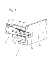
- FIG. 6 schematically a cross section through the drilling template 24 and the angular support arm 25 is shown.
- Ansetz template 241 is provided on the example, a chuck is placed.
- the attachment template 241 is preferably rotatable.
- Attachment template 241 is adjoined by an insert body 242 having a guide bore 243 for a drilling tool that terminates in an end surface 244.
- the insert body 242 penetrates the carrier arm 25 in the active state, a drilling tool is passed through the guide bore 243 of the insert body 242 and protrudes slightly beyond the end surface 244 of the insert body 242 out.
- the insert body 242 includes screw holes 245 for, for example, grub screws to fix a drill in the guide bore 243.
- the insert body 242 is mounted in a guide body 246 which is fixedly connected to the support arm 25. This has in a cylindrical interior a spring screw 247, against the resistance of the insert body 242 is pressed in the direction of a rotor blade.
- the insert body 242 is within the guide body 246 rotatably mounted.
Abstract
Description
Die Erfindung betrifft ein Verfahren, eine Vorrichtung und eine Anordnung zum Anbringen einer Referenzmarkierung an einem Rotorblatt für eine Windenergieanlage sowie eine Verwendung.The invention relates to a method, a device and an arrangement for attaching a reference marking on a rotor blade for a wind energy plant and a use.
Beim Betrieb von Windenergieanlagen führen Unwuchten, die durch verschiedene Einstellungen der Rotorblattwinkel der Rotorblätter eines Rotors entstehen, zu einer Verminderung des erreichbaren Energieertrages. Gleichzeitig gefährden sie die Integrität von Windenergieanlagen. Beim Errichten und beim Betrieb von Windenergieanlagen ist daher darauf zu achten, dass die Rotorblätter der Windenergieanlage mit identischen und vorbestimmten Einstellwinkeln betrieben werden. Hierzu verfügen die Rotorblätter üblicherweise über Referenzmarkierungen, auch 0°-Markierungen oder Nullmarkierungen genannt, die mit Markierungen auf der zentralen Rotornabe abgeglichen werden.When operating wind turbines, imbalances caused by different settings of the rotor blade angles of the rotor blades of a rotor lead to a reduction of the achievable energy yield. At the same time, they endanger the integrity of wind turbines. When erecting and operating wind turbines, it must therefore be ensured that the rotor blades of the wind turbine are operated at identical and predetermined setting angles. For this purpose, the rotor blades usually have reference marks, also called 0 ° marks or zero marks, which are aligned with marks on the central rotor hub.
Es hat sich in der Praxis gezeigt, dass fehlerhafte Referenzmarkierungen zu Rotorunwuchten und reduziertem Energieeintrag führen. Wenn dies der Fall ist, müssen die Rotorblätter neu eingemessen werden. Hierbei ist eine Genauigkeit von wenigstens 0,3° erforderlich, wünschenswert ist eine Genauigkeit von weniger als 0,1°.It has been shown in practice that faulty reference marks lead to rotor imbalances and reduced energy input. If this is the case, the rotor blades must be re-calibrated. In this case, an accuracy of at least 0.3 ° is required, an accuracy of less than 0.1 ° is desirable.
In
In
Ein übliches Verfahren zur Anbringung entsprechender Referenzmarkierungen sieht vor, dass an der fertig montierten Windenergieanlage eine Profilschablone von außen über ein Rotorblatt geschoben wird, welche dann mittels optischer Verfahren in Bezug zu einer Referenzebene, z.B. die Rotorebene oder die Rotorachsebene, eingemessen wird. Dies ist allerdings bei heutigen Größen von Windenergieanlagen mit Rotordurchmessern von weit über 100 m bei einer Anbringung derartiger Schablonen in über 50 m Höhe über dem Boden eine zeit- und kostenintensive Maßnahme.A common method for attaching corresponding reference markers provides that a profile template is pushed from the outside over a rotor blade on the fully assembled wind turbine, which then by means of optical methods with respect to a Reference plane, for example, the rotor plane or the rotor axis plane, is measured. However, this is a time-consuming and costly measure for today's sizes of wind turbines with rotor diameters of well over 100 m with a mounting of such templates in over 50 m above the ground.
Aus diesem Grund ist es inzwischen bevorzugt, Rotorblätter bereits nach deren Herstellung mit Referenzmarkierungen zu versehen, bevor sie an einer Windenergieanlage montiert werden. Hierfür ist bekannt, dass an der Außenseite am wurzelseitigen Ende eines Rotorblatts mittels eines Abwicklungsmaßes die Position für eine Nullmarkierung abgemessen wird, wobei von der Trennebene des Rotorblatts, d.h. der Ebene, die eine obere Halbschale von einer unteren Halbschale des Rotorblatts trennt, ausgegangen wird. Die Halbschalen bestehen üblicherweise aus einem mit einem Harzmaterial laminierten Verbund aus mehreren Lagen von Glas- und/oder Kohlefasermatten.For this reason, it is now preferred to provide rotor blades with reference markings already after their production, before they are mounted on a wind turbine. For this purpose, it is known that on the outside at the root end of a rotor blade by means of a development measure the position is measured for a zero mark, wherein the separation plane of the rotor blade, i. the level which separates an upper half-shell from a lower half-shell of the rotor blade, is assumed. The half-shells are usually made of a laminated with a resin material composite of several layers of glass and / or carbon fiber mats.
Schließlich sind auch Setzschablonen bekannt, die an den Innenflächen der Blattanschlusshülsen positioniert werden. Die erreichbare Genauigkeit bei diesem Verfahren hängt sowohl von der Positionierungsgenauigkeit der Hülse im Flansch als zuvor auch von der Genauigkeit der Positionierung des Flansches am Rotorblatt ab. Diese Toleranzen addieren sich auf.Finally, setting templates are known which are positioned on the inner surfaces of the sheet connection sleeves. The achievable accuracy in this method depends both on the positioning accuracy of the sleeve in the flange and previously on the accuracy of the positioning of the flange on the rotor blade. These tolerances add up.
Die zuvor beschriebenen Verfahren ermöglichen nicht die erforderliche Genauigkeit von 0,3°, vorzugsweise 0,1°, da für den an der Blattwurzel zu markierenden Nullwinkel die Neigung des Rotorblatts im Leistungsbereich maßgeblich ist, also dem äußeren, zur Spitze des Rotorblatts hin angeordneten Bereich, der den größten Leistungsbeitrag am Rotorblatt erbringt. Dementsprechend ist der 0°-Winkel bezüglich der Vorderkante des Rotorblattprofils im Leistungsbereich definiert, demgegenüber die Vorderkante des Rotorblattprofils an der Blattwurzel um einen gewissen Winkel verdreht ist. Die Nullmarkierung stimmt daher im Allgemeinen nicht mit der Position der Profilvorderkante an der Blattwurzel überein.The methods described above do not allow the required accuracy of 0.3 °, preferably 0.1 °, since the inclination of the rotor blade in the power range is decisive for the zero angle to be marked on the blade root, ie the outer region arranged towards the tip of the rotor blade , which provides the largest power contribution to the rotor blade. Accordingly, the 0 ° angle with respect to the leading edge of the rotor blade profile in the power range defined, in contrast, the leading edge of the rotor blade profile is rotated at the blade root by a certain angle. The zero mark is therefore generally inconsistent with the leading edge position of the blade root.
Das Rotorblatt ist sehr flexibel und verbiegt sich unter seinem Eigengewicht. Wenn das Profil bzw. die Profilvorderkante im Leistungsbereich senkrecht gestellt wird, ist nicht gewährleistet, dass der blattwurzelseitige Bereich in einer auf 0,1° bis 0,3° reproduzierbaren Position bzw. Winkelposition dazu steht. Aufgrund individueller Spannungen und Verzüge eines jeden Rotorblatts tritt eine Variation der Winkelverhältnisse und somit der Referenzmarkierungspunkte auf, die oberhalb des gewünschten Genauigkeitsbereiches liegt.The rotor blade is very flexible and bends under its own weight. If the profile or the leading edge of the profile is placed vertically in the power range, it is not ensured that the blade root-side range is in a position that can be reproduced at 0.1 ° to 0.3 ° or in an angular position. Due to individual stresses and distortions of each rotor blade occurs a variation of the angular ratios and thus the reference marking points, which is above the desired accuracy range.
Gegenüber diesem Stand der Technik liegt der vorliegenden Erfindung die Aufgabe zugrunde, Referenzmarkierungen an einem Rotorblatt für eine Windenergieanlage reproduzierbar und mit hoher Genauigkeit anbringen zu können.Compared to this prior art, the present invention has the object to be able to attach reference marks on a rotor blade for a wind turbine reproducible and with high accuracy.
Diese Aufgabe wird durch ein Verfahren zum Anbringen einer Referenzmarkierung an einem Rotorblatt für eine Windenergieanlage gelöst, wobei nach dem Herstellen des Rotorblatts in einer Herstellungsform und vor dem Herauslösen des Rotorblatts aus der Herstellungsform mittels einer Markierungsvorrichtung, die mit einer an einer vorbestimmten oder vorbestimmbaren Position an der Herstellungsform angeordneten Haltevorrichtung verbindbar oder verbunden ist, eine Referenzmarkierung im Bereich einer Rotorblattwurzel des Rotorblatts angebracht wird.This object is achieved by a method for attaching a reference mark on a rotor blade for a wind turbine, wherein after the manufacture of the rotor blade in a manufacturing mold and before the detachment of the rotor blade from the manufacturing mold by means of a marking device, which with a at a predetermined or predeterminable position the manufacturing form arranged holding device is connectable or connected, a reference mark in the region of a rotor blade root of the rotor blade is mounted.
Das erfindungsgemäße Verfahren hat den Vorteil, dass die Referenzmarkierung in einem Produktionsschritt eingefügt wird, in dem sich das Rotorblatt noch in seiner Herstellungsform befindet, so dass seine Position über die gesamte Länge des Rotorblatts sehr genau definiert ist. Die Markierung wird mittels eines Werkzeugs eingebracht, das fest mit der Form verbunden ist und somit ebenfalls eine genau definierte Position relativ zum Rotorblatt in seiner gesamten Länge einnimmt. Der Ungenauigkeiten verursachende Einfluss der Flexibilität des Rotorblattmaterials wird unterdrückt.The method according to the invention has the advantage that the reference marking is inserted in a production step in which the rotor blade is still in its production form, so that its position over the entire length of the rotor blade is very well defined. The marking is introduced by means of a tool which is firmly connected to the mold and thus also assumes a well-defined position relative to the rotor blade in its entire length. The inaccuracy causing influence of the flexibility of the rotor blade material is suppressed.
Hierzu ist es vorteilhaft, wenn die Markierungsvorrichtung nach der Herstellung des Rotorblatts in der Herstellungsform mit der Haltevorrichtung verbunden wird. Insbesondere für Harzinfusionsverfahren hat diese Vorgehensweise den Vorteil, dass die Markierungsvorrichtung nicht beim Injizieren von Harz in die Form stört oder im Wege steht. Dies fördert die vollständige Integrität des Materials des Rotorblatts an seinem blattwurzelseitigen Ende.For this purpose, it is advantageous if the marking device is connected to the holding device after the manufacture of the rotor blade in the production form. For resin infusion processes in particular, this approach has the advantage that the marking device does not interfere or interfere with the injection of resin into the mold. This promotes complete integrity of the rotor blade material at its blade root end.
Vorteilhafterweise wird die Referenzmarkierung an einer Innenseite des Rotorblatts angebracht. Damit wird eine, insbesondere wetterunabhängige und zeitsparende, Möglichkeit zur Vermessung von Rotorblatteinstellwinkeln geschaffen, die insbesondere für Offshore-Windenergieanlagen, die rauen klimatischen Bedingungen ausgesetzt sind, besondere Vorteile bringt.Advantageously, the reference mark is attached to an inner side of the rotor blade. This creates a, in particular weather-independent and time-saving, possibility for measuring rotor blade pitch angles, which brings particular advantages in particular for offshore wind turbines which are exposed to harsh climatic conditions.
Eine bevorzugte Art und Weise der Anbringung einer Referenzmarkierung besteht darin, dass die Referenzmarkierung mittels einer Bohrung durch eine Bohrschablone der Markierungsvorrichtung erzeugt wird. Eine Bohrung, die insbesondere nicht mehr als 5 mm (Millimeter) tief in das Material des Rotorblatts eindringt, ist gut sichtbar und einfach zu vermessen, ohne das laminierte Material und damit die strukturelle Stärke des Rotorblatts zu beeinträchtigen.A preferred way of attaching a reference mark is to create the reference mark by drilling through a drilling template of the marking device. In particular, a hole that penetrates no more than 5 mm (millimeters) deep into the material of the rotor blade is easily visible and easy to measure, without affecting the laminated material and thus the structural strength of the rotor blade.
Die der Erfindung zugrunde liegende Aufgabe wird auch durch eineThe object underlying the invention is also by a
Vorrichtung zum Anbringen einer Referenzmarkierung an einem Rotorblatt für eine Windenergieanlage, umfassend eine Haltevorrichtung und eine Markierungsvorrichtung mit einem Markierungselement, gelöst, wobei die Haltevorrichtung ausgebildet ist, mit einer Herstellungsform für ein Rotorblatt in einer vorbestimmten oder vorbestimmbaren Position in einem Bereich eines blattwurzelseitigen Endes des Rotorblatts verbindbar oder verbunden zu sein, wobei die Markierungsvorrichtung ausgebildet ist, mit der Haltevorrichtung verbindbar oder verbunden zu sein.A device for mounting a reference mark on a rotor blade for a wind turbine, comprising a holding device and a marking device with a marking element, wherein the holding device is formed with a manufacturing mold for a rotor blade in a predetermined or predeterminable position in a region of a blade root-side end of the rotor blade connectable or connected, wherein the marking device is designed to be connectable or connected to the holding device.
Die erfindungsgemäße Vorrichtung weist den bereits zum erfindungsgemäßen Verfahren genannten Vorteil auf, dass eine Haltevorrichtung für die Markierungsvorrichtung an einer vorbestimmten oder vorbestimmbaren Position an der Herstellungsform angeordnet ist und eine Markierungsvorrichtung mit der Haltevorrichtung verbunden wird. Damit erhält das Markierungselement über die Markierungsvorrichtung und die Haltevorrichtung eine vorbestimmte und reproduzierbare Position in Bezug auf die Herstellungsform für das Rotorblatt sowie jedes in der Form hergestellte und angeordnete Rotorblatt, einschließlich in Bezug auf dessen Leistungsbereich, dessen Orientierung für die Nullmarkierung maßgeblich ist.The device according to the invention has the advantage already mentioned for the method according to the invention that a holding device for the marking device is arranged at a predetermined or predeterminable position on the production mold and a marking device is connected to the holding device. Thus, the marking element receives via the marking device and the holding device a predetermined and reproducible position with respect to the manufacturing mold for the rotor blade and each manufactured and arranged in the form rotor blade, including with respect to the power range whose orientation is relevant for the zero mark.
Das Markierungselement umfasst vorteilhafterweise einen Bohrer oder einen Farbapplikator, beispielsweise einen Druckkopf, einen Pinsel mit Farbe oder einen Stift. Vorzugsweise umfasst das Markierungselement eine Bohrschablone. Eine Bohrschablone wird im Rahmen der Erfindung als ein Führungskörper mit einer zentralen durchgehenden Öffnung für einen Bohrer verstanden, der mittels der Bohrschablone in einer festen und vorgegebenen Position angesetzt werden kann.The marking element advantageously comprises a drill or a color applicator, for example a print head, a paint brush or a pen. Preferably, the marking element comprises a drilling template. A drilling template is understood in the context of the invention as a guide body with a central through hole for a drill, which can be attached by means of the drilling template in a fixed and predetermined position.
Vorteilhafterweise ist das Markierungselement in einer radialenAdvantageously, the marking element is in a radial
Richtung eines rotorblattwurzelseitigen Bereichs der Herstellungsform, insbesondere lösbar fixierbar, bewegbar. Die radiale Richtung ist im Rahmen der Erfindung über die übliche Form des rotorblattwurzelseitigen Endes eines Rotorblatts definiert, welche üblicherweise kreisförmig ist. Die radiale Richtung ist eine Richtung auf den Mittelpunkt dieses Kreises zu oder vom Mittelpunt des Kreises weg. Eine solche Bewegung verändert die Winkelposition des Markierungselements nicht. Die radiale Beweglichkeit bewirkt, dass das Markierungselement an verschiedene Dicken von Rotorblättern im blattwurzelseitigen Bereich des Rotorblatts angepasst werden kann, oder dass beispielsweise ein Bohrer oder ein Farbapplikator an die Oberfläche des Rotorblatts angenähert werden kann.Direction of a rotor blade root side region of the manufacturing form, in particular releasably fixable, movable. The radial direction is defined in the context of the invention over the usual shape of the rotor blade root end of a rotor blade, which is usually circular. The radial direction is a direction toward the center of this circle toward or away from the center point of the circle. Such a movement does not change the angular position of the marking element. The radial mobility causes the marking element to be adapted to different thicknesses of rotor blades in the blade root-side region of the rotor blade, or that, for example, a drill or a color applicator can be approximated to the surface of the rotor blade.
Vorzugsweise ist vorgesehen, dass das Markierungselement an einer Innenfläche eines Rotorblatts in der Herstellungsform angeordnet ist, wenn die Markierungsvorrichtung mit der Haltevorrichtung verbunden ist. Derart angeordnete Markierungen sind vor Witterungseinflüssen weitgehend geschützt und daher besonders langlebig.It is preferably provided that the marking element is arranged on an inner surface of a rotor blade in the production mold when the marking device is connected to the holding device. Such arranged markings are largely protected from the weather and therefore very durable.
Die der Erfindung zugrunde liegende Aufgabe wird ferner durch eine Anordnung zum Anbringen einer Referenzmarkierung an einem Rotorblatt für eine Windenergieanlage, umfassend eine Herstellungsform für ein Rotorblatt und eine zuvor beschriebene erfindungsgemäße Vorrichtung, gelöst, wobei die Haltevorrichtung mit der Herstellungsform in einer vorbestimmten oder vorbestimmbaren Position in einem Bereich eines blattwurzelseitigen Endes des Rotorblatts mit der Herstellungsform verbindbar oder verbunden ist. Diese Anordnung weist die zuvor beschriebenen erfindungsgemäßen Vorteile auf.The object underlying the invention is further achieved by an arrangement for attaching a reference mark on a rotor blade for a wind turbine, comprising a manufacturing mold for a rotor blade and a device according to the invention described above, wherein the holding device with the manufacturing mold in a predetermined or predeterminable position in a region of a blade root-side end of the rotor blade is connectable or connected to the manufacturing mold. This arrangement has the advantages according to the invention described above.
In einer bevorzugten Weiterbildung ist die Haltevorrichtung in dieIn a preferred embodiment, the holding device in the
Herstellungsform integriert. In diesem Fall ist ein Teil der Herstellungsform als Haltevorrichtung ausgebildet. Alternativ ist vorteilhafterweise die Haltevorrichtung lösbar mit der Herstellungsform verbunden.Integrated production. In this case, a part of the production form is designed as a holding device. Alternatively, advantageously, the holding device is detachably connected to the production mold.
Schließlich wird die der Erfindung zugrunde liegende Aufgabe auch durch eine Verwendung einer Vorrichtung mit einer Haltevorrichtung und einer Markierungsvorrichtung, insbesondere einer zuvor beschriebenen erfindungsgemäßen Vorrichtung, zum Anbringen einer Referenzmarkierung an einem Rotorblatt für eine Windenergieanlage gelöst, die sich dadurch auszeichnet, dass die Haltevorrichtung und die Markierungsvorrichtung beim Anbringen der Referenzmarkierung am Rotorblatt an einer vorbestimmten oder vorbestimmbaren Position an einem blattwurzelseitigen Ende einer Herstellungsform für das Rotorblatt angeordnet ist. Die zuvor beschriebenen Vorteile sind auch bei der erfindungsgemäßen Verwendung vorhanden.Finally, the object underlying the invention is also achieved by using a device with a holding device and a marking device, in particular an inventive device described above, for attaching a reference mark on a rotor blade for a wind turbine, which is characterized in that the holding device and the Marking device when attaching the reference mark on the rotor blade at a predetermined or predeterminable position at a blade root end of a manufacturing mold for the rotor blade is arranged. The advantages described above are also present in the use according to the invention.
Die Erfindung wird nachstehend ohne Beschränkung des allgemeinen Erfindungsgedankens anhand von Ausführungsbeispielen unter Bezugnahme auf die Zeichnungen beschrieben, wobei bezüglich aller im Text nicht näher erläuterten erfindungsgemäßen Einzelheiten ausdrücklich auf die Zeichnungen verwiesen wird. Es zeigen:
- Fig. 1
- eine schematische Darstellung zu einem bekannten Verfahren zum Anbringen einer Referenzmarkierung,
- Fig. 2 a), 2 b)
- schematische Darstellungen zu einem weiteren bekannten Verfahren zum Anbringen einer Referenzmarkierung,
- Fig. 3
- eine perspektivische Ansicht einer erfindungsgemäßen Vorrichtung in schematischer Darstellung,
- Fig. 4
- eine weitere perspektivische Ansicht der Vorrichtung gemäß
Fig. 3 in schematischer Darstellung, - Fig. 5
- eine schematische Darstellung einer erfindungsgemäßen Anordnung in perspektivischer Ansicht und
- Fig. 6
- eine schematische Schnittdarstellung durch eine erfindungsgemäße Markierungsvorrichtung in perspektivischer Ansicht.
- Fig. 1
- a schematic representation of a known method for applying a reference mark,
- 2 a), 2 b)
- schematic representations of another known method for applying a reference mark,
- Fig. 3
- a perspective view of a device according to the invention in a schematic representation,
- Fig. 4
- a further perspective view of the device according to
Fig. 3 in a schematic representation, - Fig. 5
- a schematic representation of an inventive arrangement in perspective view and
- Fig. 6
- a schematic sectional view through a marking device according to the invention in a perspective view.
In den folgenden Figuren sind jeweils gleiche oder gleichartige Elemente bzw. entsprechende Teile mit denselben Bezugsziffern versehen, so dass von einer entsprechenden erneuten Vorstellung abgesehen wird.In the following figures, identical or similar elements or corresponding parts are provided with the same reference numerals, so that a corresponding renewed idea is dispensed with.
In
Die Rotorblattwurzel 5 trägt eine kreisförmige Blattanschlusshülse 7. Perspektivisch dahinter in das Bild hinein ist der Leistungsbereich des Rotorblatts 1 dargestellt, der in der Rotorblattspitze 6 endet.The
Um eine Referenzmarkierung anzubringen, ist das Rotorblatt so gestellt, dass der Leistungsbereich senkrecht steht. Dafür sind zwei Profilschablonen 2 auf zwei verschiedene Positionen im Leistungsbereich des Rotorblatts 1 aufgeschoben, die jeweils mit einem Inklinometer 3 oder Neigungssensor 3 ausgerüstet sind. Anhand deren Anzeige wird bestimmt, wann der Leistungsbereich des Rotorblatts 1 senkrecht steht.To attach a reference mark, the rotor blade is set so that the power range is vertical. For this purpose, two
In der Blattanschlusshülse 7 ist eine 0°-Vorrichtung 4 zum Anbringen einer Nullmarkierung im Bereich der Blattwurzel angeordnet. Die 0°-Vorrichtung umfasst einen Arm, dessen Länge dem Durchmesser der Rotorblattwurzel 5 entspricht, sowie einen zweiten Arm, der halb so lang ist und im Mittelpunkt der Rotorblattwurzel 5 am ersten Arm angelenkt ist. Der erste Arm orientiert sich an der Ausrichtung des Rotorblatts 1 im Bereich der Blattwurzel 5 und steht unter einem Winkel zum Leistungsbereich. Der kürzere zweite Arm ist mit einem Inklinometer 3 ausgerüstet und wird zur Einmessung des Nullwinkels bzw. einer Nullmarkierung verwendet.In the
Das in
In
Die Setzschablone 12 umfasst einen Referenz-Pin 13 sowie ein Sichtfenster 14, durch das Bolzen 11 der Blattanschlusshülse 7 sichtbar sind. Unterhalb und oberhalb des Rotorblatts weist die Setzschablone Markierungsfähnchen 15 auf, zwischen denen eine Nullmarkierung gesetzt werden kann.The setting
In
Außerdem ist die Blattanschlusshülse 7 auf dem blattwurzelseitigen Ende der Schalen nicht ganz genau und reproduzierbar anbringbar, so dass auch nicht gewährleistet ist, dass die Bolzen 11 der Blattanschlusshülse 7 beispielsweise in Bezug auf die Stoßkante 10 immer die gleichen Relativpositionen einnehmen. Das führt zu einer weiteren Quelle von Ungenauigkeiten beim Anbringen von Markierungspositionen.In addition, the
In
Die Markierungsvorrichtung 23 umfasst in
In
In
Die Haltevorrichtung 21 ist an der Herstellungsform 34 angebracht, wobei diese an einer festen, vorbestimmten Position gegenüber der Herstellungsform 34 angeordnet ist. An der Haltevorrichtung 21 ist in
In
Der Einsatzkörper 242 umfasst Schraubbohrungen 245 für bspw. Madenschrauben, um einen Bohrer in der Führungsbohrung 243 zu fixieren.The
Der Einsatzkörper 242 ist in einem Führungskörper 246 gelagert, der mit dem Trägerarm 25 fest verbunden ist. Dieser weist in einem zylindrischen Innenraum eine Federschraube 247 auf, gegen den Widerstand der Einsatzkörper 242 in Richtung auf ein Rotorblatt gedrückt wird. Der Einsatzkörper 242 ist innerhalb des Führungskörpers 246 rotierbar gelagert.The
Alle genannten Merkmale, auch die den Zeichnungen allein zu entnehmenden sowie auch einzelne Merkmale, die in Kombination mit anderen Merkmalen offenbart sind, werden allein und in Kombination als erfindungswesentlich angesehen. Erfindungsgemäße Ausführungsformen können durch einzelne Merkmale oder eine Kombination mehrerer Merkmale erfüllt sein.All mentioned features, including the drawings alone to be taken as well as individual features that are disclosed in combination with other features are considered alone and in combination as essential to the invention. Embodiments of the invention may be accomplished by individual features or a combination of several features.
- 11
- Rotorblattrotor blade
- 22
- Profilschabloneprofile template
- 33
- Inklinometerinclinometer
- 44
- 0°-Vorrichtung für die Blattwurzel0 ° device for the leaf root
- 55
- RotorblattwurzelRotor blade root
- 66
- RotorblattspitzeRotor blade tip
- 77
- BlattanschlusshülseBlade attachment sleeve
- 88th
- Hinterkantetrailing edge
- 99
- Vorderkanteleading edge
- 1010
- Stoßkanteimpact edge
- 1111
- Bolzenbolt
- 1212
- Setzschablonesetting template
- 1313
- Referenz-PinReference Pin
- 1414
- Sichtfensterwindow
- 1515
- MarkierungsfähnchenBoundary flag
- 2020
- Vorrichtung zum Anbringen einer ReferenzmarkierungDevice for applying a reference mark
- 2121
- Haltevorrichtungholder
- 2222
- Befestigungsplattemounting plate
- 2323
- Markierungsvorrichtungmarking device
- 2424
- Bohrschablonedrilling template
- 241241
- AnsetzschabloneAnsetzschablone
- 242242
- Einsatzkörperinsert body
- 243243
- Führungsbohrungguide bore
- 244244
- Endflächeend face
- 245245
- Schraubbohrungscrew hole
- 246246
- Führungskörperguide body
- 247247
- Federschraubespring screw
- 2525
- Trägerarmsupport arm
- 2626
- Abstandhalterspacer
- 2727
- LanglochLong hole
- 2828
- Handgriffhandle
- 3030
- Innenseite eines RotorblattsInside of a rotor blade
- 3131
- Stoßkanteimpact edge
- 3232
- Obere HalbschaleUpper half shell
- 3333
- Untere HalbschaleLower half shell
- 3434
- Herstellungsform für die untere HalbschaleProduction mold for the lower half shell
- 34'34 '
- oberer Abschluss der Herstellungsformupper conclusion of the production form
- 3535
- Stützpfeilerbuttress
Claims (11)
Applications Claiming Priority (1)
| Application Number | Priority Date | Filing Date | Title |
|---|---|---|---|
| DE102010002230.6A DE102010002230B4 (en) | 2010-02-23 | 2010-02-23 | Method and device for attaching a reference mark on a rotor blade for a wind turbine |
Publications (3)
| Publication Number | Publication Date |
|---|---|
| EP2362094A2 true EP2362094A2 (en) | 2011-08-31 |
| EP2362094A3 EP2362094A3 (en) | 2012-10-31 |
| EP2362094B1 EP2362094B1 (en) | 2014-06-11 |
Family
ID=43639933
Family Applications (1)
| Application Number | Title | Priority Date | Filing Date |
|---|---|---|---|
| EP11152225.6A Not-in-force EP2362094B1 (en) | 2010-02-23 | 2011-01-26 | Method and device for attaching a reference marking to a rotor blade of a wind turbine |
Country Status (6)
| Country | Link |
|---|---|
| US (1) | US8585948B2 (en) |
| EP (1) | EP2362094B1 (en) |
| CN (1) | CN102162425B (en) |
| DE (1) | DE102010002230B4 (en) |
| DK (1) | DK2362094T3 (en) |
| ES (1) | ES2494240T3 (en) |
Cited By (4)
| Publication number | Priority date | Publication date | Assignee | Title |
|---|---|---|---|---|
| CN102581406A (en) * | 2012-02-16 | 2012-07-18 | 哈尔滨汽轮机厂有限责任公司 | Electric spark perforation clamp for heat component gas die holes of gas turbine |
| WO2013182569A1 (en) * | 2012-06-05 | 2013-12-12 | Technische Universität München | Method for installing sensors in rotor blades and installation device |
| EP3190290A1 (en) * | 2013-11-27 | 2017-07-12 | Nordex Energy GmbH | Wind energy assembly rotor blade for a rotor with a spinner |
| DE102018104052A1 (en) | 2018-02-22 | 2019-08-22 | Nordex Energy Gmbh | Method for applying a marking on the inner surface of a rotor blade half shell of a wind energy plant |
Families Citing this family (8)
| Publication number | Priority date | Publication date | Assignee | Title |
|---|---|---|---|---|
| CN102500650A (en) * | 2011-10-19 | 2012-06-20 | 赵党生 | Method for making positioning mark on one-step formed component |
| BR112014018031B1 (en) * | 2012-01-25 | 2020-12-01 | Safran | process and tool for making a propeller blade |
| ES2878050T3 (en) * | 2014-04-24 | 2021-11-18 | Lm Wp Patent Holding As | A system and procedure for manufacturing wind turbine blades |
| EP3279470B1 (en) * | 2016-08-06 | 2021-11-03 | Nidec SSB Wind Systems GmbH | Method for pitch angle measuring and/or for establishing a measuring system for pitch angle measuring |
| CN110480331B (en) * | 2019-09-17 | 2024-03-19 | 河北大唐国际新能源有限公司 | Device for calibrating zero-position installation angle of fan blade |
| ES2823548B2 (en) * | 2019-11-06 | 2021-12-16 | Comercial De Utiles Y Moldes Sa | Dating system for molds |
| EP3854560A1 (en) * | 2020-01-27 | 2021-07-28 | Siemens Gamesa Renewable Energy A/S | Method for fabricating a wind turbine shell, wind turbine blade, wind turbine and method for repair of a wind turbine blade shell |
| CN114701185B (en) * | 2022-01-11 | 2024-03-12 | 中材科技风电叶片股份有限公司 | Blade preparation method |
Citations (2)
| Publication number | Priority date | Publication date | Assignee | Title |
|---|---|---|---|---|
| DE19628073C1 (en) | 1996-07-12 | 1997-09-18 | Aerodyn Energiesysteme Gmbh | Wind-powered generation plant rotor blade angle correction method |
| DE202007008066U1 (en) | 2007-06-08 | 2008-10-23 | Repower Systems Ag | Device for aligning an angle-adjustable rotor blade of a wind energy plant and wind energy plant |
Family Cites Families (5)
| Publication number | Priority date | Publication date | Assignee | Title |
|---|---|---|---|---|
| US4226536A (en) * | 1979-02-23 | 1980-10-07 | Dreyfus Marc G | Electro-optical contour measuring system |
| JPH08101018A (en) * | 1994-09-30 | 1996-04-16 | Sintokogio Ltd | Method for measuring dimension of mold and mold-related parts by using laser length measuring instrument |
| JP2003039217A (en) * | 2001-08-02 | 2003-02-12 | Honda Motor Co Ltd | Guide-jig for hand drill |
| US8741196B2 (en) * | 2006-01-31 | 2014-06-03 | The Boeing Company | Method and apparatus for locating and drilling a hole in a composite |
| DK200700647A (en) * | 2007-04-30 | 2008-05-10 | Lm Glasfiber As | Measurement of geometric parameters for a wind turbine blade |
-
2010
- 2010-02-23 DE DE102010002230.6A patent/DE102010002230B4/en not_active Expired - Fee Related
-
2011
- 2011-01-26 DK DK11152225.6T patent/DK2362094T3/en active
- 2011-01-26 EP EP11152225.6A patent/EP2362094B1/en not_active Not-in-force
- 2011-01-26 ES ES11152225.6T patent/ES2494240T3/en active Active
- 2011-02-16 US US13/028,726 patent/US8585948B2/en not_active Expired - Fee Related
- 2011-02-21 CN CN2011100412578A patent/CN102162425B/en not_active Expired - Fee Related
Patent Citations (2)
| Publication number | Priority date | Publication date | Assignee | Title |
|---|---|---|---|---|
| DE19628073C1 (en) | 1996-07-12 | 1997-09-18 | Aerodyn Energiesysteme Gmbh | Wind-powered generation plant rotor blade angle correction method |
| DE202007008066U1 (en) | 2007-06-08 | 2008-10-23 | Repower Systems Ag | Device for aligning an angle-adjustable rotor blade of a wind energy plant and wind energy plant |
Cited By (5)
| Publication number | Priority date | Publication date | Assignee | Title |
|---|---|---|---|---|
| CN102581406A (en) * | 2012-02-16 | 2012-07-18 | 哈尔滨汽轮机厂有限责任公司 | Electric spark perforation clamp for heat component gas die holes of gas turbine |
| WO2013182569A1 (en) * | 2012-06-05 | 2013-12-12 | Technische Universität München | Method for installing sensors in rotor blades and installation device |
| US9284950B2 (en) | 2012-06-05 | 2016-03-15 | Technische Universität München | Method for installation of sensors in rotor blades and installation apparatus |
| EP3190290A1 (en) * | 2013-11-27 | 2017-07-12 | Nordex Energy GmbH | Wind energy assembly rotor blade for a rotor with a spinner |
| DE102018104052A1 (en) | 2018-02-22 | 2019-08-22 | Nordex Energy Gmbh | Method for applying a marking on the inner surface of a rotor blade half shell of a wind energy plant |
Also Published As
| Publication number | Publication date |
|---|---|
| US20110204542A1 (en) | 2011-08-25 |
| ES2494240T3 (en) | 2014-09-15 |
| EP2362094A3 (en) | 2012-10-31 |
| US8585948B2 (en) | 2013-11-19 |
| CN102162425A (en) | 2011-08-24 |
| DE102010002230A1 (en) | 2011-08-25 |
| EP2362094B1 (en) | 2014-06-11 |
| DE102010002230B4 (en) | 2014-11-27 |
| DK2362094T3 (en) | 2014-09-01 |
| CN102162425B (en) | 2013-08-07 |
Similar Documents
| Publication | Publication Date | Title |
|---|---|---|
| EP2362094B1 (en) | Method and device for attaching a reference marking to a rotor blade of a wind turbine | |
| DE102009046586B4 (en) | Blade tip for a rotor blade of a wind turbine and method for mounting the blade tip to a rotor blade | |
| EP2261501B1 (en) | Method and device for mounting a rotor blade for a wind energy plant | |
| EP2383092A1 (en) | Device and unit mould for the production of rotor blades for wind energy facilities and method for producing same | |
| EP3018342B2 (en) | Method for producing a rotor blade of a wind turbine | |
| DE102014009478A1 (en) | Manipulator with a manipulator arm | |
| DE102012221262A1 (en) | Device system with a positioning device for determining a borehole center | |
| EP3074183B1 (en) | Bridge setting device, bridge, and production method for a rotor blade of a wind power plant | |
| DE102011087049A1 (en) | Method for joining components on a shaft | |
| DE102005013752A1 (en) | Drill resistance measuring apparatus for calibrating drilling operations, detects drilling tool characteristics via motor power and test body | |
| EP2282244A1 (en) | Device for processing workpieces | |
| EP3421229B1 (en) | Method for positioning fibrous construction components | |
| DE102018104052A1 (en) | Method for applying a marking on the inner surface of a rotor blade half shell of a wind energy plant | |
| DE19826086A1 (en) | Rotor blade for wind power generators and rotor blade manufacture | |
| DE102012003378A1 (en) | Forming blind bond between components of wind energy plant rotor blade, involves applying adhesive on first and second adhesive surfaces of first and second components, placing components in final position, and curing second component | |
| DE102009050861A1 (en) | Device for setting a roundwood | |
| DE102010044972B4 (en) | stylus arrangement | |
| EP3321503A1 (en) | Method for projecting a marking within a rotor blade of a wind turbine | |
| EP2197092B1 (en) | Method for fitting a resolver and electrical machine | |
| DE102005019875B4 (en) | Drilling jig and drilling device | |
| DE102012002717A1 (en) | Rotor blade for wind turbine, comprises rotor blade structure, which is provided with embedded marking element and sensor, which are designed to provide information that allows conclusions about angle of incidence of rotor blade | |
| DE102014010778B4 (en) | Alignment devices for use with a drilling machine guided on a drilling machine stand, use of the alignment devices and method for aligning a drilling machine stand | |
| DE19858910A1 (en) | Hinge drilling jig | |
| DE102019122122B4 (en) | Device and method for removing material from the surface of an arrangement of profile elements and an intermediate transition area with cured filling compound, as well as manufacturing method | |
| DE102009050478B4 (en) | Method of manufacturing a cargo gate and cargo gate |
Legal Events
| Date | Code | Title | Description |
|---|---|---|---|
| PUAI | Public reference made under article 153(3) epc to a published international application that has entered the european phase |
Free format text: ORIGINAL CODE: 0009012 |
|
| AK | Designated contracting states |
Kind code of ref document: A2 Designated state(s): AL AT BE BG CH CY CZ DE DK EE ES FI FR GB GR HR HU IE IS IT LI LT LU LV MC MK MT NL NO PL PT RO RS SE SI SK SM TR |
|
| AX | Request for extension of the european patent |
Extension state: BA ME |
|
| PUAL | Search report despatched |
Free format text: ORIGINAL CODE: 0009013 |
|
| AK | Designated contracting states |
Kind code of ref document: A3 Designated state(s): AL AT BE BG CH CY CZ DE DK EE ES FI FR GB GR HR HU IE IS IT LI LT LU LV MC MK MT NL NO PL PT RO RS SE SI SK SM TR |
|
| AX | Request for extension of the european patent |
Extension state: BA ME |
|
| RIC1 | Information provided on ipc code assigned before grant |
Ipc: B29D 99/00 20100101ALI20120921BHEP Ipc: B25H 7/00 20060101ALI20120921BHEP Ipc: F03D 1/00 20060101ALI20120921BHEP Ipc: B23B 47/28 20060101ALI20120921BHEP Ipc: B29C 70/54 20060101ALI20120921BHEP Ipc: F03D 11/00 20060101AFI20120921BHEP |
|
| 17P | Request for examination filed |
Effective date: 20130326 |
|
| REG | Reference to a national code |
Ref country code: DE Ref legal event code: R079 Ref document number: 502011003340 Country of ref document: DE Free format text: PREVIOUS MAIN CLASS: F03D0011000000 Ipc: B29C0059020000 |
|
| GRAP | Despatch of communication of intention to grant a patent |
Free format text: ORIGINAL CODE: EPIDOSNIGR1 |
|
| RIC1 | Information provided on ipc code assigned before grant |
Ipc: F03D 11/00 20060101ALI20130917BHEP Ipc: B29C 59/02 20060101AFI20130917BHEP Ipc: B23B 47/28 20060101ALI20130917BHEP Ipc: B29L 31/08 20060101ALI20130917BHEP Ipc: F03D 1/00 20060101ALI20130917BHEP |
|
| INTG | Intention to grant announced |
Effective date: 20131018 |
|
| RAP1 | Party data changed (applicant data changed or rights of an application transferred) |
Owner name: REPOWER SYSTEMS SE |
|
| GRAP | Despatch of communication of intention to grant a patent |
Free format text: ORIGINAL CODE: EPIDOSNIGR1 |
|
| GRAS | Grant fee paid |
Free format text: ORIGINAL CODE: EPIDOSNIGR3 |
|
| INTG | Intention to grant announced |
Effective date: 20140410 |
|
| GRAA | (expected) grant |
Free format text: ORIGINAL CODE: 0009210 |
|
| AK | Designated contracting states |
Kind code of ref document: B1 Designated state(s): AL AT BE BG CH CY CZ DE DK EE ES FI FR GB GR HR HU IE IS IT LI LT LU LV MC MK MT NL NO PL PT RO RS SE SI SK SM TR |
|
| RAP1 | Party data changed (applicant data changed or rights of an application transferred) |
Owner name: SENVION SE |
|
| REG | Reference to a national code |
Ref country code: GB Ref legal event code: FG4D Free format text: NOT ENGLISH |
|
| REG | Reference to a national code |
Ref country code: CH Ref legal event code: EP |
|
| REG | Reference to a national code |
Ref country code: IE Ref legal event code: FG4D Free format text: LANGUAGE OF EP DOCUMENT: GERMAN |
|
| REG | Reference to a national code |
Ref country code: AT Ref legal event code: REF Ref document number: 672028 Country of ref document: AT Kind code of ref document: T Effective date: 20140715 |
|
| REG | Reference to a national code |
Ref country code: DE Ref legal event code: R096 Ref document number: 502011003340 Country of ref document: DE Effective date: 20140724 |
|
| REG | Reference to a national code |
Ref country code: DK Ref legal event code: T3 Effective date: 20140827 |
|
| REG | Reference to a national code |
Ref country code: ES Ref legal event code: FG2A Ref document number: 2494240 Country of ref document: ES Kind code of ref document: T3 Effective date: 20140915 |
|
| PG25 | Lapsed in a contracting state [announced via postgrant information from national office to epo] |
Ref country code: NO Free format text: LAPSE BECAUSE OF FAILURE TO SUBMIT A TRANSLATION OF THE DESCRIPTION OR TO PAY THE FEE WITHIN THE PRESCRIBED TIME-LIMIT Effective date: 20140911 Ref country code: LT Free format text: LAPSE BECAUSE OF FAILURE TO SUBMIT A TRANSLATION OF THE DESCRIPTION OR TO PAY THE FEE WITHIN THE PRESCRIBED TIME-LIMIT Effective date: 20140611 Ref country code: FI Free format text: LAPSE BECAUSE OF FAILURE TO SUBMIT A TRANSLATION OF THE DESCRIPTION OR TO PAY THE FEE WITHIN THE PRESCRIBED TIME-LIMIT Effective date: 20140611 Ref country code: GR Free format text: LAPSE BECAUSE OF FAILURE TO SUBMIT A TRANSLATION OF THE DESCRIPTION OR TO PAY THE FEE WITHIN THE PRESCRIBED TIME-LIMIT Effective date: 20140912 |
|
| REG | Reference to a national code |
Ref country code: NL Ref legal event code: VDEP Effective date: 20140611 |
|
| REG | Reference to a national code |
Ref country code: LT Ref legal event code: MG4D |
|
| PG25 | Lapsed in a contracting state [announced via postgrant information from national office to epo] |
Ref country code: LV Free format text: LAPSE BECAUSE OF FAILURE TO SUBMIT A TRANSLATION OF THE DESCRIPTION OR TO PAY THE FEE WITHIN THE PRESCRIBED TIME-LIMIT Effective date: 20140611 Ref country code: RS Free format text: LAPSE BECAUSE OF FAILURE TO SUBMIT A TRANSLATION OF THE DESCRIPTION OR TO PAY THE FEE WITHIN THE PRESCRIBED TIME-LIMIT Effective date: 20140611 Ref country code: HR Free format text: LAPSE BECAUSE OF FAILURE TO SUBMIT A TRANSLATION OF THE DESCRIPTION OR TO PAY THE FEE WITHIN THE PRESCRIBED TIME-LIMIT Effective date: 20140611 Ref country code: SE Free format text: LAPSE BECAUSE OF FAILURE TO SUBMIT A TRANSLATION OF THE DESCRIPTION OR TO PAY THE FEE WITHIN THE PRESCRIBED TIME-LIMIT Effective date: 20140611 |
|
| RAP2 | Party data changed (patent owner data changed or rights of a patent transferred) |
Owner name: SENVION SE |
|
| PG25 | Lapsed in a contracting state [announced via postgrant information from national office to epo] |
Ref country code: RO Free format text: LAPSE BECAUSE OF FAILURE TO SUBMIT A TRANSLATION OF THE DESCRIPTION OR TO PAY THE FEE WITHIN THE PRESCRIBED TIME-LIMIT Effective date: 20140611 Ref country code: PT Free format text: LAPSE BECAUSE OF FAILURE TO SUBMIT A TRANSLATION OF THE DESCRIPTION OR TO PAY THE FEE WITHIN THE PRESCRIBED TIME-LIMIT Effective date: 20141013 Ref country code: CZ Free format text: LAPSE BECAUSE OF FAILURE TO SUBMIT A TRANSLATION OF THE DESCRIPTION OR TO PAY THE FEE WITHIN THE PRESCRIBED TIME-LIMIT Effective date: 20140611 Ref country code: EE Free format text: LAPSE BECAUSE OF FAILURE TO SUBMIT A TRANSLATION OF THE DESCRIPTION OR TO PAY THE FEE WITHIN THE PRESCRIBED TIME-LIMIT Effective date: 20140611 Ref country code: SK Free format text: LAPSE BECAUSE OF FAILURE TO SUBMIT A TRANSLATION OF THE DESCRIPTION OR TO PAY THE FEE WITHIN THE PRESCRIBED TIME-LIMIT Effective date: 20140611 |
|
| PG25 | Lapsed in a contracting state [announced via postgrant information from national office to epo] |
Ref country code: PL Free format text: LAPSE BECAUSE OF FAILURE TO SUBMIT A TRANSLATION OF THE DESCRIPTION OR TO PAY THE FEE WITHIN THE PRESCRIBED TIME-LIMIT Effective date: 20140611 Ref country code: IS Free format text: LAPSE BECAUSE OF FAILURE TO SUBMIT A TRANSLATION OF THE DESCRIPTION OR TO PAY THE FEE WITHIN THE PRESCRIBED TIME-LIMIT Effective date: 20141011 Ref country code: NL Free format text: LAPSE BECAUSE OF FAILURE TO SUBMIT A TRANSLATION OF THE DESCRIPTION OR TO PAY THE FEE WITHIN THE PRESCRIBED TIME-LIMIT Effective date: 20140611 |
|
| REG | Reference to a national code |
Ref country code: DE Ref legal event code: R097 Ref document number: 502011003340 Country of ref document: DE |
|
| PLBE | No opposition filed within time limit |
Free format text: ORIGINAL CODE: 0009261 |
|
| STAA | Information on the status of an ep patent application or granted ep patent |
Free format text: STATUS: NO OPPOSITION FILED WITHIN TIME LIMIT |
|
| PG25 | Lapsed in a contracting state [announced via postgrant information from national office to epo] |
Ref country code: IT Free format text: LAPSE BECAUSE OF FAILURE TO SUBMIT A TRANSLATION OF THE DESCRIPTION OR TO PAY THE FEE WITHIN THE PRESCRIBED TIME-LIMIT Effective date: 20140611 |
|
| 26N | No opposition filed |
Effective date: 20150312 |
|
| REG | Reference to a national code |
Ref country code: DE Ref legal event code: R097 Ref document number: 502011003340 Country of ref document: DE Effective date: 20150312 |
|
| PG25 | Lapsed in a contracting state [announced via postgrant information from national office to epo] |
Ref country code: BE Free format text: LAPSE BECAUSE OF NON-PAYMENT OF DUE FEES Effective date: 20150131 |
|
| PG25 | Lapsed in a contracting state [announced via postgrant information from national office to epo] |
Ref country code: SI Free format text: LAPSE BECAUSE OF FAILURE TO SUBMIT A TRANSLATION OF THE DESCRIPTION OR TO PAY THE FEE WITHIN THE PRESCRIBED TIME-LIMIT Effective date: 20140611 |
|
| REG | Reference to a national code |
Ref country code: DE Ref legal event code: R082 Ref document number: 502011003340 Country of ref document: DE Representative=s name: SEEMANN & PARTNER PATENTANWAELTE MBB, DE Ref country code: DE Ref legal event code: R082 Ref document number: 502011003340 Country of ref document: DE Representative=s name: PATENTANWAELTE SEEMANN & PARTNER, DE Ref country code: DE Ref legal event code: R081 Ref document number: 502011003340 Country of ref document: DE Owner name: SENVION GMBH, DE Free format text: FORMER OWNER: SENVION SE, 22297 HAMBURG, DE Ref country code: DE Ref legal event code: R082 Ref document number: 502011003340 Country of ref document: DE Representative=s name: WALLINGER RICKER SCHLOTTER TOSTMANN PATENT- UN, DE |
|
| REG | Reference to a national code |
Ref country code: CH Ref legal event code: PL |
|
| PG25 | Lapsed in a contracting state [announced via postgrant information from national office to epo] |
Ref country code: LU Free format text: LAPSE BECAUSE OF FAILURE TO SUBMIT A TRANSLATION OF THE DESCRIPTION OR TO PAY THE FEE WITHIN THE PRESCRIBED TIME-LIMIT Effective date: 20150126 |
|
| PG25 | Lapsed in a contracting state [announced via postgrant information from national office to epo] |
Ref country code: MC Free format text: LAPSE BECAUSE OF FAILURE TO SUBMIT A TRANSLATION OF THE DESCRIPTION OR TO PAY THE FEE WITHIN THE PRESCRIBED TIME-LIMIT Effective date: 20140611 |
|
| PG25 | Lapsed in a contracting state [announced via postgrant information from national office to epo] |
Ref country code: CH Free format text: LAPSE BECAUSE OF NON-PAYMENT OF DUE FEES Effective date: 20150131 Ref country code: LI Free format text: LAPSE BECAUSE OF NON-PAYMENT OF DUE FEES Effective date: 20150131 |
|
| REG | Reference to a national code |
Ref country code: IE Ref legal event code: MM4A |
|
| REG | Reference to a national code |
Ref country code: FR Ref legal event code: PLFP Year of fee payment: 6 |
|
| PG25 | Lapsed in a contracting state [announced via postgrant information from national office to epo] |
Ref country code: IE Free format text: LAPSE BECAUSE OF NON-PAYMENT OF DUE FEES Effective date: 20150126 |
|
| PG25 | Lapsed in a contracting state [announced via postgrant information from national office to epo] |
Ref country code: MT Free format text: LAPSE BECAUSE OF FAILURE TO SUBMIT A TRANSLATION OF THE DESCRIPTION OR TO PAY THE FEE WITHIN THE PRESCRIBED TIME-LIMIT Effective date: 20140611 |
|
| REG | Reference to a national code |
Ref country code: FR Ref legal event code: PLFP Year of fee payment: 7 |
|
| REG | Reference to a national code |
Ref country code: AT Ref legal event code: MM01 Ref document number: 672028 Country of ref document: AT Kind code of ref document: T Effective date: 20160126 |
|
| PG25 | Lapsed in a contracting state [announced via postgrant information from national office to epo] |
Ref country code: AT Free format text: LAPSE BECAUSE OF NON-PAYMENT OF DUE FEES Effective date: 20160126 Ref country code: BG Free format text: LAPSE BECAUSE OF FAILURE TO SUBMIT A TRANSLATION OF THE DESCRIPTION OR TO PAY THE FEE WITHIN THE PRESCRIBED TIME-LIMIT Effective date: 20140611 Ref country code: SM Free format text: LAPSE BECAUSE OF FAILURE TO SUBMIT A TRANSLATION OF THE DESCRIPTION OR TO PAY THE FEE WITHIN THE PRESCRIBED TIME-LIMIT Effective date: 20140611 Ref country code: HU Free format text: LAPSE BECAUSE OF FAILURE TO SUBMIT A TRANSLATION OF THE DESCRIPTION OR TO PAY THE FEE WITHIN THE PRESCRIBED TIME-LIMIT; INVALID AB INITIO Effective date: 20110126 |
|
| PG25 | Lapsed in a contracting state [announced via postgrant information from national office to epo] |
Ref country code: CY Free format text: LAPSE BECAUSE OF FAILURE TO SUBMIT A TRANSLATION OF THE DESCRIPTION OR TO PAY THE FEE WITHIN THE PRESCRIBED TIME-LIMIT Effective date: 20140611 |
|
| PG25 | Lapsed in a contracting state [announced via postgrant information from national office to epo] |
Ref country code: TR Free format text: LAPSE BECAUSE OF FAILURE TO SUBMIT A TRANSLATION OF THE DESCRIPTION OR TO PAY THE FEE WITHIN THE PRESCRIBED TIME-LIMIT Effective date: 20140611 |
|
| REG | Reference to a national code |
Ref country code: FR Ref legal event code: PLFP Year of fee payment: 8 |
|
| REG | Reference to a national code |
Ref country code: DE Ref legal event code: R082 Ref document number: 502011003340 Country of ref document: DE Representative=s name: WALLINGER RICKER SCHLOTTER TOSTMANN PATENT- UN, DE |
|
| PG25 | Lapsed in a contracting state [announced via postgrant information from national office to epo] |
Ref country code: MK Free format text: LAPSE BECAUSE OF FAILURE TO SUBMIT A TRANSLATION OF THE DESCRIPTION OR TO PAY THE FEE WITHIN THE PRESCRIBED TIME-LIMIT Effective date: 20140611 |
|
| PG25 | Lapsed in a contracting state [announced via postgrant information from national office to epo] |
Ref country code: AL Free format text: LAPSE BECAUSE OF FAILURE TO SUBMIT A TRANSLATION OF THE DESCRIPTION OR TO PAY THE FEE WITHIN THE PRESCRIBED TIME-LIMIT Effective date: 20140611 |
|
| PGFP | Annual fee paid to national office [announced via postgrant information from national office to epo] |
Ref country code: FR Payment date: 20210120 Year of fee payment: 11 |
|
| PGFP | Annual fee paid to national office [announced via postgrant information from national office to epo] |
Ref country code: DE Payment date: 20210120 Year of fee payment: 11 Ref country code: GB Payment date: 20210122 Year of fee payment: 11 Ref country code: ES Payment date: 20210217 Year of fee payment: 11 Ref country code: DK Payment date: 20210120 Year of fee payment: 11 |
|
| REG | Reference to a national code |
Ref country code: DE Ref legal event code: R119 Ref document number: 502011003340 Country of ref document: DE |
|
| REG | Reference to a national code |
Ref country code: DK Ref legal event code: EBP Effective date: 20220131 |
|
| GBPC | Gb: european patent ceased through non-payment of renewal fee |
Effective date: 20220126 |
|
| PG25 | Lapsed in a contracting state [announced via postgrant information from national office to epo] |
Ref country code: GB Free format text: LAPSE BECAUSE OF NON-PAYMENT OF DUE FEES Effective date: 20220126 Ref country code: DE Free format text: LAPSE BECAUSE OF NON-PAYMENT OF DUE FEES Effective date: 20220802 |
|
| PG25 | Lapsed in a contracting state [announced via postgrant information from national office to epo] |
Ref country code: FR Free format text: LAPSE BECAUSE OF NON-PAYMENT OF DUE FEES Effective date: 20220131 |
|
| PG25 | Lapsed in a contracting state [announced via postgrant information from national office to epo] |
Ref country code: DK Free format text: LAPSE BECAUSE OF NON-PAYMENT OF DUE FEES Effective date: 20220131 |
|
| REG | Reference to a national code |
Ref country code: ES Ref legal event code: FD2A Effective date: 20230330 |
|
| PG25 | Lapsed in a contracting state [announced via postgrant information from national office to epo] |
Ref country code: ES Free format text: LAPSE BECAUSE OF NON-PAYMENT OF DUE FEES Effective date: 20220127 |