EP2282244A1 - Device for processing workpieces - Google Patents
Device for processing workpieces Download PDFInfo
- Publication number
- EP2282244A1 EP2282244A1 EP10007882A EP10007882A EP2282244A1 EP 2282244 A1 EP2282244 A1 EP 2282244A1 EP 10007882 A EP10007882 A EP 10007882A EP 10007882 A EP10007882 A EP 10007882A EP 2282244 A1 EP2282244 A1 EP 2282244A1
- Authority
- EP
- European Patent Office
- Prior art keywords
- workpiece
- tool
- measurement
- tools
- data
- Prior art date
- Legal status (The legal status is an assumption and is not a legal conclusion. Google has not performed a legal analysis and makes no representation as to the accuracy of the status listed.)
- Withdrawn
Links
Images
Classifications
-
- G—PHYSICS
- G05—CONTROLLING; REGULATING
- G05B—CONTROL OR REGULATING SYSTEMS IN GENERAL; FUNCTIONAL ELEMENTS OF SUCH SYSTEMS; MONITORING OR TESTING ARRANGEMENTS FOR SUCH SYSTEMS OR ELEMENTS
- G05B19/00—Programme-control systems
- G05B19/02—Programme-control systems electric
- G05B19/18—Numerical control [NC], i.e. automatically operating machines, in particular machine tools, e.g. in a manufacturing environment, so as to execute positioning, movement or co-ordinated operations by means of programme data in numerical form
- G05B19/404—Numerical control [NC], i.e. automatically operating machines, in particular machine tools, e.g. in a manufacturing environment, so as to execute positioning, movement or co-ordinated operations by means of programme data in numerical form characterised by control arrangements for compensation, e.g. for backlash, overshoot, tool offset, tool wear, temperature, machine construction errors, load, inertia
Definitions
- the manufacturing accuracy can be sufficiently ensured by means of this known measurement of workpieces in the clamping and a high reject rate can be prevented.
- the present invention is therefore based on the object to provide a way to work largely deformed even in itself deformed, especially curved workpieces in a machine tool.
- the workpiece is no longer measured on the clamping device but in the region of the tool (s). In this way, any deviations of the workpiece with regard to its position in the machine tool and / or its shape can be detected at the point at which the tool also attaches later. It can therefore position or shape errors of workpieces are compensated with much higher accuracy in the machining result than with the known methods.
- the use of the method according to the invention is therefore particularly advantageous for woodworking machines, since workpieces made of wood, due to their relatively inhomogeneous material properties, are more prone to curvatures or the like than, for example, workpieces made of metal.
- the measuring device for the workpiece can preferably only be moved into the processing area for the actual measuring operation and then moved out again.
- the measurement of the workpiece can be made mechanically or optically.
- probing heads can be provided which can be set against the workpiece at different points on the surface of the workpiece.
- any fixed point of the machine tool can be used in the area of the processing unit.
- laser scanning of the workpiece can also be carried out.
- this method a highly accurate image of the workpiece and its position can be obtained, whereby the compensation of the position and / or shape error of the workpiece in the machining result can be done with high quality.
- control of the tool or tools or the workpiece movement device can be such that the deviation of the measured data from the desired data of the workpiece with respect to at least one property of the machining result such as cutting angle, machining depth, machining length or the like is completely compensated.
- the length of the cut surface is more crucial than the angle of the cut or vice versa. If it depends on both properties, so can Processing result are almost met.
- the invention further relates to a machine tool for machining workpieces, in particular workpieces made of wood, with a clamping device for the workpiece and at least one processing unit with one or more tools and with a device for workpiece measurement, which is characterized in that the workpiece in the area of the processing unit can be measured by means of the device for workpiece measurement.
- the device for workpiece measurement can for this purpose have one or more engagable against the workpiece probes or a laser scanner. An optical measurement of the workpiece and its position by means of cameras is also possible.
- the device for workpiece measurement is connected to the control of at least the processing unit, wherein the evaluation of the measurement signals is carried out in an evaluation device.
- the comparison of the measured data with the desired data of an ideal and error-free clamped workpiece takes place.
- the control data for the tool or tools are modified accordingly. If the workpiece is moved past stationary tools in the machine tool, a change of the movement data for the workpiece can take place in the same way, so that an at least substantial compensation of the position or shape error of the workpiece can take place in the machining result.
- Fig. 1 shows a workpiece 10 in the form of a wooden beam, which has been provided at its tip 11 in an earlier processing step with an oblique saw cut 12.
- the workpiece 10 is clamped in a clamping device 13, of which two clamping jaws 13.1 and 13.2 are shown.
- the jaw 13.2 is stationary, while the jaw 13.1 can be opened.
- a tool 14, here a saw blade is shown, with which a second, obliquely running saw cut is to be introduced into the workpiece 10.
- the saw blade 14 can be pivoted in the example shown in the direction of the double arrow 15, so that the cutting angle of the saw cut can be adjusted.
- Fig. 1 also shows a device 16 for measuring the workpiece 10.
- the device 16 is arranged in the region of the saw blade 14, ie in the region of the next processing of the workpiece 10.
- two probes 17 and 18 are shown, each having tips 17.1 and 18.1, which are movable against the surface of the workpiece 10.
- four probes may be predetermined for all sides of the workpiece 10. In this way, both the position of the workpiece 10 and its Determine dimension in the area of the circular saw blade 14. Any deviations of the measured data from predetermined desired data can be compensated for, at least with regard to the cutting angle, by the saw blade 14 being correspondingly pivoted in one of the directions of the double arrow 15. It is also possible to compensate for errors by changing the starting point of the saw cut.
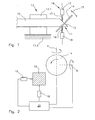
- Fig. 2 the compensation of possible workpiece errors or clamping errors of the workpiece to the machining result is clarified.
- the workpiece 10 can now be seen from the front in the schematic figure. From the measuring device 16 are again the lower probe 18 and a in Fig. 1 not to be seen lateral probe 19 shown. All of the probes 17, 18, 19 measure the distance of the surfaces of the workpiece 10 from a reference point, which is not shown, but can be arranged at any fixed location on the machine.
- the measured data are then transmitted to a central evaluation and control device 20 of the machine tool. There, a comparison of the measured data with stored in a memory of the device 20 target data on the dimensions and position of the workpiece 10 takes place. Due to possibly detected deviations of the measured data from the ideal state, the saw blade 14, which is pivotable about the two axes A and B, is then actuated with respect to the pivot angle about these axes and with respect to the point of action of the saw blade 14 on the workpiece 10 such that the influence of the deviation of the Workpiece 10 from the ideal state to the desired Processing result is minimized as possible.
- the compensation of the measured deviations can also extend only to one of the various properties of the processing result.
- the activation of the saw blade 14 can also take place in such a way that a compromise is achieved between all desired properties of the machining result of the workpiece 10.
Abstract
Description
Bei modernen Werkzeugmaschinen ist es üblich, die Lage eines Werkstücks im Bereich der Einspannung zu vermessen. Die Lage des Werkstücks wird dabei in Bezug auf die Einspannvorrichtung bestimmt. Treten dabei Verschiebungen zu einer idealen Einspannung auf, so kann entweder die Einspannung des Werkstücks noch einmal korrigiert werden, oder aber es werden die Fertigungsdaten der nachfolgenden Bearbeitung auf die reale Position des Werkstücks umgerechnet, um sicherzustellen, dass das Werkstück fehlerfrei bearbeitet wird.In modern machine tools, it is customary to measure the position of a workpiece in the region of the clamping. The position of the workpiece is determined in relation to the clamping device. If displacements to an ideal clamping occur, then either the clamping of the workpiece can be corrected again, or it will be the manufacturing data of subsequent processing to the real position of the workpiece converted to ensure that the workpiece is processed error-free.
Bei Werkstücken, die bereits vorbearbeitet sind und bei denen ein nur sehr geringer Abstand zwischen Einspannung und Angriffspunkt des Werkzeugs besteht, kann mittels dieser bekannten Vermessung von Werkstücken im Bereich der Einspannung die Fertigungsgenauigkeit ausreichend gewährleistet und eine hohe Ausschussquote verhindert werden.For workpieces that are already prepared and in which there is only a very small distance between clamping and application point of the tool, the manufacturing accuracy can be sufficiently ensured by means of this known measurement of workpieces in the clamping and a high reject rate can be prevented.
Insbesondere bei längeren Werkstücken, die aus einem Naturmaterial wie Holz bestehen oder die aufgrund vorhergehender Bearbeitungsschritte thermischen oder mechanischen Spannungen ausgesetzt waren, ist die Abweichung der Werkstücksposition bzw. seiner Form von den Idealwerten am Angriffspunkt des Werkzeugs deutlich unterschiedlich zu der Abweichung im Einspannbereich. Insbesondere Krümmungen des Werkstücks können dazu führen, dass mit dem bisher bekannten Einmessverfahren trotz Korrektur der Fertigungsdaten einer CNCgesteuerten Werkzeugmaschine Ausschussware im größeren Umfang produziert wird. Gerade bei schrägen Sägenschnitten an gekrümmten Werkstücken treten sowohl Fehler des Schnittwinkels als auch der Länge der Schnittfläche auf. Sollen solchermaßen bearbeitete Werkstücke später mit anderen Werkstücken zusammengefügt werden, kann der fehlerhaft eingebrachte Sägeschnitt dazu führen, dass das Werkstück unbrauchbar wird.Especially with longer workpieces that consist of a natural material such as wood or that were exposed to thermal or mechanical stresses due to previous processing steps, the deviation of the workpiece position or its shape from the ideal values at the point of application of the tool is significantly different from the deviation in the clamping area. In particular, curvatures of the workpiece can lead to the fact that with the previously known Einmessverfahren despite correction of the manufacturing data of a CNC machine tool rejects on a larger scale is produced. Especially with oblique saw cuts on curved workpieces both errors of the cutting angle and the length of the cut surface occur. If such machined workpieces are later joined together with other workpieces, the incorrectly inserted saw cut can lead to the workpiece becoming unusable.
Der vorliegenden Erfindung liegt daher die Aufgabe zugrunde, eine Möglichkeit zu schaffen, auch in sich verformte, insbesondere gekrümmte Werkstücke in einer Werkzeugmaschine weitgehend fehlerfrei zu bearbeiten.The present invention is therefore based on the object to provide a way to work largely deformed even in itself deformed, especially curved workpieces in a machine tool.
Die Aufgabe wird gelöst mit einem Verfahren zur Bearbeitung von Werkstücken in einer Werkzeugmaschine, das gekennzeichnet ist durch die Schritte:
- Einspannen des Werkstücks in der Werkzeugmaschine;
- Vermessen des Werkstücks und/oder seiner Position im Bereich des oder der Werkzeuge;
- Vergleich der Messdaten mit Solldaten für das Werkstück;
- Ansteuerung des oder der Werkzeuge und/oder einer Werkstückbewegungseinrichtung in Abhängigkeit von der Differenz zwischen den Messdaten und den Solldaten derart, dass durch die relative Positionierung und/oder Bewegung des oder der Werkzeuge in Bezug auf das Werkstück der Einfluss der Abweichung der Messdaten von den Solldaten auf das Bearbeitungsergebnis zumindest teilweise kompensiert wird.
- Clamping the workpiece in the machine tool;
- Measuring the workpiece and / or its position in the region of the tool or tools;
- Comparison of the measured data with target data for the workpiece;
- Actuation of the tool or tools and / or a workpiece movement device as a function of the difference between the measurement data and the target data in such a way that the relative positioning and / or movement of the tool or tools with respect to the workpiece influences the deviation of the measurement data from the target data is at least partially compensated for the processing result.
Im Gegensatz zu den Einmessverfahren bekannter Werkzeugmaschinen wird nach dem erfindungsgemäßen Verfahren das Werkstück nicht mehr an der Einspannvorrichtung, sondern im Bereich des oder der Werkzeuge vermessen. Damit lassen sich eventuelle Abweichungen des Werkstücks hinsichtlich seiner Lage in der Werkzeugmaschine und/oder seiner Form an derjenigen Stelle erfassen, an der später auch das Werkzeug ansetzt.
Es können daher Positions- oder Formfehler von Werkstücken mit sehr viel höherer Genauigkeit im Bearbeitungsergebnis kompensiert werden als mit den bekannten Verfahren. Der Einsatz des erfindungsgemäßen Verfahrens ist daher insbesondere für Holzbearbeitungsmaschinen von Vorteil, da Werkstücke aus Holz aufgrund ihrer relativ inhomogenen Materialbeschaffenheit stärker zu Krümmungen oder dergleichen neigen als beispielsweise Werkstücke aus Metall.In contrast to the calibration methods of known machine tools, according to the method of the invention, the workpiece is no longer measured on the clamping device but in the region of the tool (s). In this way, any deviations of the workpiece with regard to its position in the machine tool and / or its shape can be detected at the point at which the tool also attaches later.
It can therefore position or shape errors of workpieces are compensated with much higher accuracy in the machining result than with the known methods. The use of the method according to the invention is therefore particularly advantageous for woodworking machines, since workpieces made of wood, due to their relatively inhomogeneous material properties, are more prone to curvatures or the like than, for example, workpieces made of metal.
Um die spätere Bearbeitung des Werkstücks durch das oder die Werkzeuge nicht zu behindern, kann die Messeinrichtung für das Werkstück vorzugsweise nur für den eigentlichen Messvorgang in den Bearbeitungsbereich hineinbewegt und anschließend wieder herausbewegt werden.In order not to hinder the later processing of the workpiece by the tool or tools, the measuring device for the workpiece can preferably only be moved into the processing area for the actual measuring operation and then moved out again.
Als Messmethode für die Werkstücksposition und die Form bzw. die Maße des Werkstücks können sämtliche bekannten Messverfahren eingesetzt werden. Vorzugsweise kann die Vermessung des Werkstücks mechanisch oder optisch erfolgen. Zur mechanischen Vermessung können beispielsweise Tastköpfe vorgesehen sein, die gegen das Werkstück an verschiedenen Stellen der Oberfläche des Werkstücks anstellbar sind. Als Referenzpunkt für die Messung kann jeder beliebige feststehende Punkt der Werkzeugmaschine im Bereich des Bearbeitungsaggregats herangezogen werden.As a measuring method for the workpiece position and the shape or the dimensions of the workpiece, all known measuring methods can be used. Preferably, the measurement of the workpiece can be made mechanically or optically. For mechanical measurement, for example, probing heads can be provided which can be set against the workpiece at different points on the surface of the workpiece. As a reference point for the measurement, any fixed point of the machine tool can be used in the area of the processing unit.
Anstelle der mechanischen Vermessung mittels eines oder mehrerer Tastköpfe kann auch ein Laserscannen des Werkstücks durchgeführt werden. Mit diesem Verfahren lässt sich eine ausgesprochen präzise Abbildung des Werkstücks und seiner Lage gewinnen, wodurch auch die Kompensation der Positions- und/oder Formfehler des Werkstücks im Bearbeitungsergebnis mit hoher Qualität erfolgen kann.Instead of the mechanical measurement by means of one or more probes, laser scanning of the workpiece can also be carried out. With this method, a highly accurate image of the workpiece and its position can be obtained, whereby the compensation of the position and / or shape error of the workpiece in the machining result can be done with high quality.
Bei einer bevorzugten Ausgestaltung des erfindungsgemäßen Verfahrens kann die Ansteuerung des oder der Werkzeuge oder der Werkstückbewegungseinrichtung derart erfolgen, dass die Abweichung der Messdaten von den Solldaten des Werkstücks hinsichtlich mindestens einer Eigenschaft des Bearbeitungsergebnisses wie Schnittwinkel, Bearbeitungstiefe, Bearbeitungslänge oder dergleichen vollständig kompensiert wird.In a preferred embodiment of the method according to the invention, the control of the tool or tools or the workpiece movement device can be such that the deviation of the measured data from the desired data of the workpiece with respect to at least one property of the machining result such as cutting angle, machining depth, machining length or the like is completely compensated.
Je nach Abweichung der Lage oder Form des Werkstücks vom Idealzustand lassen sich diese Abweichungen im Bearbeitungsergebnis nicht vollständig kompensieren. In diesen Fällen muss entschieden werden, welches Kriterium des Bearbeitungsergebnisses zwingend erfüllt sein muss, um das bearbeitete Werkstück anschließend weiter verwenden zu können. Es wird dann durch eine entsprechende Ansteuerung der Werkzeuge oder der Werkstückbewegung versucht, diese Eigenschaft vollständig entsprechend dem Idealzustand zu erzielen, während die Erfüllung anderer Eigenschaften demgegenüber zweitrangig behandelt wird.Depending on the deviation of the position or shape of the workpiece from the ideal state, these deviations in the machining result can not be completely compensated. In these cases, it must be decided which criterion of the machining result must be met in order to continue using the machined workpiece. It is then attempted by an appropriate control of the tools or the workpiece movement to achieve this property completely in accordance with the ideal state, while the fulfillment of other properties is treated in contrast secondary.
Gerade bei schrägen Sägeschnitten an längeren Hölzern ist in manchen Fällen die Länge der Schnittfläche entscheidender als der Winkel des Schnitts oder umgekehrt. Kommt es auf beide Eigenschaften an, so kann Bearbeitungsergebnis annähernd erfüllt sind.Especially with oblique saw cuts on longer woods in some cases, the length of the cut surface is more crucial than the angle of the cut or vice versa. If it depends on both properties, so can Processing result are almost met.
Die Erfindung betrifft außerdem eine Werkzeugmaschine für die Bearbeitung von Werkstücken, insbesondere von Werkstücken aus Holz, mit einer Spanneinrichtung für das Werkstück und mindestens einem Bearbeitungsaggregat mit einem oder mehreren Werkzeugen und mit einer Einrichtung zur Werkstückvermessung, die dadurch gekennzeichnet ist, dass das Werkstück im Bereich des Bearbeitungsaggregats mit Hilfe der Einrichtung zur Werkstückvermessung vermessbar ist. Die Einrichtung zur Werkstückvermessung kann dazu einen oder mehrere gegen das Werkstück anstellbare Tastköpfe oder einen Laserscanner aufweisen. Auch eine optische Vermessung des Werkstück und seiner Position mittels Kameras ist möglich.The invention further relates to a machine tool for machining workpieces, in particular workpieces made of wood, with a clamping device for the workpiece and at least one processing unit with one or more tools and with a device for workpiece measurement, which is characterized in that the workpiece in the area of the processing unit can be measured by means of the device for workpiece measurement. The device for workpiece measurement can for this purpose have one or more engagable against the workpiece probes or a laser scanner. An optical measurement of the workpiece and its position by means of cameras is also possible.
In allen Fällen ist die Einrichtung zur Werkstückvermessung mit der Steuerung zumindest des Bearbeitungsaggregats verbunden, wobei die Auswertung der Messsignale in einer Auswerteeinrichtung vorgenommen wird. Dort findet der Vergleich der Messdaten mit den Solldaten eines idealen und fehlerfrei eingespannten Werkstücks statt. Aufgrund der festgestellten Abweichung zwischen Mess- und Solldaten werden die Ansteuerungsdaten für das oder die Werkzeuge entsprechend modifiziert. Wird in der Werkzeugmaschine das Werkstück an feststehenden Werkzeugen vorbeibewegt, so kann auf gleiche Weise eine Veränderung der Bewegungsdaten für das Werkstück erfolgen, sodass im Bearbeitungsergebnis eine zumindest weitgehende Kompensation der Lage- oder Formfehler des Werkstücks erfolgen kann.In all cases, the device for workpiece measurement is connected to the control of at least the processing unit, wherein the evaluation of the measurement signals is carried out in an evaluation device. There, the comparison of the measured data with the desired data of an ideal and error-free clamped workpiece takes place. Due to the detected deviation between measured and setpoint data, the control data for the tool or tools are modified accordingly. If the workpiece is moved past stationary tools in the machine tool, a change of the movement data for the workpiece can take place in the same way, so that an at least substantial compensation of the position or shape error of the workpiece can take place in the machining result.
Nachfolgend wird anhand der Zeichnung das erfindungsgemäße Verfahren in einer schematischen Darstellung näher verdeutlicht.The method of the invention is illustrated in more detail in a schematic representation with reference to the drawing.
Es zeigen:
- Fig. 1
- eine schematische Darstellung einer Einspannvorrichtung einer Werkzeugmaschine mit Werkstückmesseinrichtung und Werkzeug;
- Fig. 2
- eine Prinzipdarstellung einer Werkstückvermessung und Ansteuerung eines Werkzeugs.
- Fig. 1
- a schematic representation of a clamping device of a machine tool with workpiece measuring device and tool;
- Fig. 2
- a schematic representation of a workpiece measurement and control of a tool.
In
Die Messdaten werden anschließend an eine zentrale Auswerte- und Steuereinrichtung 20 der Werkzeugmaschine übermittelt. Dort findet ein Vergleich der Messdaten mit in einem Speicher der Vorrichtung 20 hinterlegten Solldaten über die Abmessungen und Position des Werkstücks 10 statt. Aufgrund eventuell festgestellter Abweichungen der Messdaten vom Idealzustand wird anschließend das Sägeblatt 14, das um die beiden Achsen A und B schwenkbar ist, bezüglich des Schwenkwinkels um diese Achsen sowie bezüglich des Angriffspunktes des Sägeblatts 14 am Werkstück 10 derart angesteuert, dass der Einfluss der Abweichung des Werkstücks 10 vom Idealzustand auf das gewünschte
Bearbeitungsergebnis möglichst minimiert wird.The measured data are then transmitted to a central evaluation and
Processing result is minimized as possible.
Die Kompensation der gemessenen Abweichungen kann sich dabei auch nur auf eine der verschiedenen Eigenschaften des Bearbeitungsergebnisses erstrecken. Alternativ kann die Ansteuerung des Sägeblatts 14 auch derart erfolgen, dass ein Kompromiss zwischen sämtlichen gewünschten Eigenschaften des Bearbeitungsergebnisses des Werkstücks 10 erzielt wird.The compensation of the measured deviations can also extend only to one of the various properties of the processing result. Alternatively, the activation of the
Claims (9)
Applications Claiming Priority (1)
| Application Number | Priority Date | Filing Date | Title |
|---|---|---|---|
| DE102009036013A DE102009036013A1 (en) | 2009-08-04 | 2009-08-04 | Method for machining workpieces |
Publications (1)
| Publication Number | Publication Date |
|---|---|
| EP2282244A1 true EP2282244A1 (en) | 2011-02-09 |
Family
ID=43086505
Family Applications (1)
| Application Number | Title | Priority Date | Filing Date |
|---|---|---|---|
| EP10007882A Withdrawn EP2282244A1 (en) | 2009-08-04 | 2010-07-29 | Device for processing workpieces |
Country Status (3)
| Country | Link |
|---|---|
| US (1) | US20110030848A1 (en) |
| EP (1) | EP2282244A1 (en) |
| DE (1) | DE102009036013A1 (en) |
Cited By (2)
| Publication number | Priority date | Publication date | Assignee | Title |
|---|---|---|---|---|
| EP2821869A1 (en) * | 2013-07-04 | 2015-01-07 | MicroStep spol. s r.o. | CNC machine for cutting with plasma, oxy-fuel, and water jet, capable of direct or additional bevel cutting, using autocalibration for self-adjustment, and the method of its adjustment by autocalibration |
| CN106271884A (en) * | 2016-08-31 | 2017-01-04 | 山东豪迈机械制造有限公司 | A kind of machining detection device and detection method |
Families Citing this family (3)
| Publication number | Priority date | Publication date | Assignee | Title |
|---|---|---|---|---|
| JP6467646B2 (en) * | 2014-03-27 | 2019-02-13 | パナソニックIpマネジメント株式会社 | Robot control method |
| ITUB20156072A1 (en) * | 2015-12-02 | 2017-06-02 | Scm Group Spa | Improved wood processing machine and its method of operation. |
| ITUB20160226A1 (en) * | 2016-02-03 | 2017-08-03 | Qdesign S R L A Socio Unico | Machine tool update system |
Citations (5)
| Publication number | Priority date | Publication date | Assignee | Title |
|---|---|---|---|---|
| US5361470A (en) * | 1992-12-03 | 1994-11-08 | Matsushita Electric Industrial Co., Ltd. | Processing apparatus with movable processing tool |
| DE19607599A1 (en) * | 1996-02-29 | 1997-09-04 | Hueller Hille Gmbh | Procedure for correcting the position determination of workpieces and tools in processing machines |
| DE10214880A1 (en) * | 2002-04-04 | 2003-10-23 | Erwin Rothballer | Robot arm programming method in which process movement commands are automatically adjusted for workpiece condition or state data, such as temperature and or material properties |
| DE202004017649U1 (en) * | 2004-11-13 | 2005-02-10 | Weinmann Holzbausystemtechnik Gmbh | Machine tool for planar workpieces has a tool holder that can be automatically controlled and moved over the whole length and breadth of the support table |
| WO2006102517A2 (en) * | 2005-03-23 | 2006-09-28 | Hurco Companies, Inc. | Method of tolerance-based trajectory planning and control |
Family Cites Families (2)
| Publication number | Priority date | Publication date | Assignee | Title |
|---|---|---|---|---|
| DE2657844A1 (en) * | 1976-12-21 | 1978-06-29 | Licentia Gmbh | DEVICE FOR MONITORING A NUMERICAL CONTROL |
| DE102007016056B4 (en) * | 2007-04-03 | 2011-08-25 | Sauer GmbH LASERTEC, 87437 | Method and device for workpiece measurement and workpiece machining |
-
2009
- 2009-08-04 DE DE102009036013A patent/DE102009036013A1/en not_active Ceased
-
2010
- 2010-07-29 US US12/846,195 patent/US20110030848A1/en not_active Abandoned
- 2010-07-29 EP EP10007882A patent/EP2282244A1/en not_active Withdrawn
Patent Citations (5)
| Publication number | Priority date | Publication date | Assignee | Title |
|---|---|---|---|---|
| US5361470A (en) * | 1992-12-03 | 1994-11-08 | Matsushita Electric Industrial Co., Ltd. | Processing apparatus with movable processing tool |
| DE19607599A1 (en) * | 1996-02-29 | 1997-09-04 | Hueller Hille Gmbh | Procedure for correcting the position determination of workpieces and tools in processing machines |
| DE10214880A1 (en) * | 2002-04-04 | 2003-10-23 | Erwin Rothballer | Robot arm programming method in which process movement commands are automatically adjusted for workpiece condition or state data, such as temperature and or material properties |
| DE202004017649U1 (en) * | 2004-11-13 | 2005-02-10 | Weinmann Holzbausystemtechnik Gmbh | Machine tool for planar workpieces has a tool holder that can be automatically controlled and moved over the whole length and breadth of the support table |
| WO2006102517A2 (en) * | 2005-03-23 | 2006-09-28 | Hurco Companies, Inc. | Method of tolerance-based trajectory planning and control |
Cited By (2)
| Publication number | Priority date | Publication date | Assignee | Title |
|---|---|---|---|---|
| EP2821869A1 (en) * | 2013-07-04 | 2015-01-07 | MicroStep spol. s r.o. | CNC machine for cutting with plasma, oxy-fuel, and water jet, capable of direct or additional bevel cutting, using autocalibration for self-adjustment, and the method of its adjustment by autocalibration |
| CN106271884A (en) * | 2016-08-31 | 2017-01-04 | 山东豪迈机械制造有限公司 | A kind of machining detection device and detection method |
Also Published As
| Publication number | Publication date |
|---|---|
| DE102009036013A1 (en) | 2011-02-17 |
| US20110030848A1 (en) | 2011-02-10 |
Similar Documents
| Publication | Publication Date | Title |
|---|---|---|
| EP2093537B1 (en) | Process and device for the determination of the alignment of two rotatable machine parts | |
| EP3456453A1 (en) | Method and device for skiving | |
| WO2016206943A1 (en) | Scanning head with integrated beam position sensor and adjustment arrangement for an off-line adjustment | |
| DE102009021483B3 (en) | Device and method for position and position determination | |
| AT511195B1 (en) | METHOD FOR REDUCING THE ECCENTRICITY OF THE INTERIOR TO EXTERNAL SURFACE | |
| EP2282244A1 (en) | Device for processing workpieces | |
| CH696876A5 (en) | Method and apparatus for round-machining a blank. | |
| EP3345723A1 (en) | Method for controlling a machine tool | |
| EP1908544A2 (en) | Method and device for laser beam processing | |
| DE102011115834A1 (en) | Method for adjusting holding unit for holding workpiece used in motor vehicle, involves adjusting position of support surface based on the comparison of actual position and desired position of support surface | |
| DE102020121446A1 (en) | Workpiece processing system and method for operating a workpiece processing system | |
| DE10322762A1 (en) | Holder for a blank and method for measuring the position and orientation of the holder | |
| DE102008001631A1 (en) | Sawing device and distance determination method | |
| DE10239694A1 (en) | A method for calibrating the position of a milling cutter has a spherical adaptor fitted to the cutter made to contact a calibration ball to establish the position coordinates | |
| DE102007048588A1 (en) | Method for reworking an externally prefabricated molded part | |
| EP2995391A2 (en) | Calibration method for a bending machine and such a bending machine | |
| DE10304430B3 (en) | Procedure for calibrating a grinding machine | |
| DE102014208304B4 (en) | Machine for processing wood panels | |
| EP3255515B1 (en) | Method for operating a cnc machine | |
| EP2743023B1 (en) | Measuring device for measuring curvature | |
| WO2008000411A1 (en) | Method and device for measuring unmachined parts | |
| DE4243393A1 (en) | Device and method for electroerosive cutting | |
| EP0692349A2 (en) | Positioning device, in particular for sawing or milling machines | |
| DE102010012973B4 (en) | Method and device for producing a stamping mold | |
| DE10319711A1 (en) | High accuracy interferometric object measurement procedure uses rotary table and additional adjustment on coordinate measuring machine to align measurement and laser axes |
Legal Events
| Date | Code | Title | Description |
|---|---|---|---|
| PUAI | Public reference made under article 153(3) epc to a published international application that has entered the european phase |
Free format text: ORIGINAL CODE: 0009012 |
|
| AK | Designated contracting states |
Kind code of ref document: A1 Designated state(s): AL AT BE BG CH CY CZ DE DK EE ES FI FR GB GR HR HU IE IS IT LI LT LU LV MC MK MT NL NO PL PT RO SE SI SK SM TR |
|
| AX | Request for extension of the european patent |
Extension state: BA ME RS |
|
| 17P | Request for examination filed |
Effective date: 20110719 |
|
| 17Q | First examination report despatched |
Effective date: 20121127 |
|
| STAA | Information on the status of an ep patent application or granted ep patent |
Free format text: STATUS: THE APPLICATION IS DEEMED TO BE WITHDRAWN |
|
| 18D | Application deemed to be withdrawn |
Effective date: 20130409 |