EP2282244A1 - Procédé de traitement de pièces usinées - Google Patents
Procédé de traitement de pièces usinées Download PDFInfo
- Publication number
- EP2282244A1 EP2282244A1 EP10007882A EP10007882A EP2282244A1 EP 2282244 A1 EP2282244 A1 EP 2282244A1 EP 10007882 A EP10007882 A EP 10007882A EP 10007882 A EP10007882 A EP 10007882A EP 2282244 A1 EP2282244 A1 EP 2282244A1
- Authority
- EP
- European Patent Office
- Prior art keywords
- workpiece
- tool
- measurement
- tools
- data
- Prior art date
- Legal status (The legal status is an assumption and is not a legal conclusion. Google has not performed a legal analysis and makes no representation as to the accuracy of the status listed.)
- Withdrawn
Links
Images
Classifications
-
- G—PHYSICS
- G05—CONTROLLING; REGULATING
- G05B—CONTROL OR REGULATING SYSTEMS IN GENERAL; FUNCTIONAL ELEMENTS OF SUCH SYSTEMS; MONITORING OR TESTING ARRANGEMENTS FOR SUCH SYSTEMS OR ELEMENTS
- G05B19/00—Programme-control systems
- G05B19/02—Programme-control systems electric
- G05B19/18—Numerical control [NC], i.e. automatically operating machines, in particular machine tools, e.g. in a manufacturing environment, so as to execute positioning, movement or co-ordinated operations by means of programme data in numerical form
- G05B19/404—Numerical control [NC], i.e. automatically operating machines, in particular machine tools, e.g. in a manufacturing environment, so as to execute positioning, movement or co-ordinated operations by means of programme data in numerical form characterised by control arrangements for compensation, e.g. for backlash, overshoot, tool offset, tool wear, temperature, machine construction errors, load, inertia
Definitions
- the manufacturing accuracy can be sufficiently ensured by means of this known measurement of workpieces in the clamping and a high reject rate can be prevented.
- the present invention is therefore based on the object to provide a way to work largely deformed even in itself deformed, especially curved workpieces in a machine tool.
- the workpiece is no longer measured on the clamping device but in the region of the tool (s). In this way, any deviations of the workpiece with regard to its position in the machine tool and / or its shape can be detected at the point at which the tool also attaches later. It can therefore position or shape errors of workpieces are compensated with much higher accuracy in the machining result than with the known methods.
- the use of the method according to the invention is therefore particularly advantageous for woodworking machines, since workpieces made of wood, due to their relatively inhomogeneous material properties, are more prone to curvatures or the like than, for example, workpieces made of metal.
- the measuring device for the workpiece can preferably only be moved into the processing area for the actual measuring operation and then moved out again.
- the measurement of the workpiece can be made mechanically or optically.
- probing heads can be provided which can be set against the workpiece at different points on the surface of the workpiece.
- any fixed point of the machine tool can be used in the area of the processing unit.
- laser scanning of the workpiece can also be carried out.
- this method a highly accurate image of the workpiece and its position can be obtained, whereby the compensation of the position and / or shape error of the workpiece in the machining result can be done with high quality.
- control of the tool or tools or the workpiece movement device can be such that the deviation of the measured data from the desired data of the workpiece with respect to at least one property of the machining result such as cutting angle, machining depth, machining length or the like is completely compensated.
- the length of the cut surface is more crucial than the angle of the cut or vice versa. If it depends on both properties, so can Processing result are almost met.
- the invention further relates to a machine tool for machining workpieces, in particular workpieces made of wood, with a clamping device for the workpiece and at least one processing unit with one or more tools and with a device for workpiece measurement, which is characterized in that the workpiece in the area of the processing unit can be measured by means of the device for workpiece measurement.
- the device for workpiece measurement can for this purpose have one or more engagable against the workpiece probes or a laser scanner. An optical measurement of the workpiece and its position by means of cameras is also possible.
- the device for workpiece measurement is connected to the control of at least the processing unit, wherein the evaluation of the measurement signals is carried out in an evaluation device.
- the comparison of the measured data with the desired data of an ideal and error-free clamped workpiece takes place.
- the control data for the tool or tools are modified accordingly. If the workpiece is moved past stationary tools in the machine tool, a change of the movement data for the workpiece can take place in the same way, so that an at least substantial compensation of the position or shape error of the workpiece can take place in the machining result.
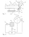
- Fig. 1 shows a workpiece 10 in the form of a wooden beam, which has been provided at its tip 11 in an earlier processing step with an oblique saw cut 12.
- the workpiece 10 is clamped in a clamping device 13, of which two clamping jaws 13.1 and 13.2 are shown.
- the jaw 13.2 is stationary, while the jaw 13.1 can be opened.
- a tool 14, here a saw blade is shown, with which a second, obliquely running saw cut is to be introduced into the workpiece 10.
- the saw blade 14 can be pivoted in the example shown in the direction of the double arrow 15, so that the cutting angle of the saw cut can be adjusted.
- Fig. 1 also shows a device 16 for measuring the workpiece 10.
- the device 16 is arranged in the region of the saw blade 14, ie in the region of the next processing of the workpiece 10.
- two probes 17 and 18 are shown, each having tips 17.1 and 18.1, which are movable against the surface of the workpiece 10.
- four probes may be predetermined for all sides of the workpiece 10. In this way, both the position of the workpiece 10 and its Determine dimension in the area of the circular saw blade 14. Any deviations of the measured data from predetermined desired data can be compensated for, at least with regard to the cutting angle, by the saw blade 14 being correspondingly pivoted in one of the directions of the double arrow 15. It is also possible to compensate for errors by changing the starting point of the saw cut.
- Fig. 2 the compensation of possible workpiece errors or clamping errors of the workpiece to the machining result is clarified.
- the workpiece 10 can now be seen from the front in the schematic figure. From the measuring device 16 are again the lower probe 18 and a in Fig. 1 not to be seen lateral probe 19 shown. All of the probes 17, 18, 19 measure the distance of the surfaces of the workpiece 10 from a reference point, which is not shown, but can be arranged at any fixed location on the machine.
- the measured data are then transmitted to a central evaluation and control device 20 of the machine tool. There, a comparison of the measured data with stored in a memory of the device 20 target data on the dimensions and position of the workpiece 10 takes place. Due to possibly detected deviations of the measured data from the ideal state, the saw blade 14, which is pivotable about the two axes A and B, is then actuated with respect to the pivot angle about these axes and with respect to the point of action of the saw blade 14 on the workpiece 10 such that the influence of the deviation of the Workpiece 10 from the ideal state to the desired Processing result is minimized as possible.
- the compensation of the measured deviations can also extend only to one of the various properties of the processing result.
- the activation of the saw blade 14 can also take place in such a way that a compromise is achieved between all desired properties of the machining result of the workpiece 10.
Landscapes
- Engineering & Computer Science (AREA)
- Human Computer Interaction (AREA)
- Manufacturing & Machinery (AREA)
- Physics & Mathematics (AREA)
- General Physics & Mathematics (AREA)
- Automation & Control Theory (AREA)
- Automatic Control Of Machine Tools (AREA)
- Machine Tool Sensing Apparatuses (AREA)
Applications Claiming Priority (1)
| Application Number | Priority Date | Filing Date | Title |
|---|---|---|---|
| DE102009036013A DE102009036013A1 (de) | 2009-08-04 | 2009-08-04 | Verfahren zur Bearbeitung von Werkstücken |
Publications (1)
| Publication Number | Publication Date |
|---|---|
| EP2282244A1 true EP2282244A1 (fr) | 2011-02-09 |
Family
ID=43086505
Family Applications (1)
| Application Number | Title | Priority Date | Filing Date |
|---|---|---|---|
| EP10007882A Withdrawn EP2282244A1 (fr) | 2009-08-04 | 2010-07-29 | Procédé de traitement de pièces usinées |
Country Status (3)
| Country | Link |
|---|---|
| US (1) | US20110030848A1 (fr) |
| EP (1) | EP2282244A1 (fr) |
| DE (1) | DE102009036013A1 (fr) |
Cited By (2)
| Publication number | Priority date | Publication date | Assignee | Title |
|---|---|---|---|---|
| EP2821869A1 (fr) * | 2013-07-04 | 2015-01-07 | MicroStep spol. s r.o. | Machine CNC de découpe par plasma, oxy-carburant et jet d'eau, permettant une découpe directe ou en biseau supplémentaire, utilisant l'auto-étalonnage pour un auto-réglage et son procédé de réglage par auto-étalonnage |
| CN106271884A (zh) * | 2016-08-31 | 2017-01-04 | 山东豪迈机械制造有限公司 | 一种机械加工用探测装置及探测方法 |
Families Citing this family (3)
| Publication number | Priority date | Publication date | Assignee | Title |
|---|---|---|---|---|
| US10152034B2 (en) * | 2014-03-27 | 2018-12-11 | Panasonic Intellectual Property Management Co., Ltd. | Robot control method for processing a workpiece on a processing line |
| ITUB20156072A1 (it) * | 2015-12-02 | 2017-06-02 | Scm Group Spa | Macchina di lavorazione del legno perfezionata e relativo metodo di funzionamento. |
| ITUB20160226A1 (it) * | 2016-02-03 | 2017-08-03 | Qdesign S R L A Socio Unico | Sistema di aggiornamento di una macchina utensile |
Citations (5)
| Publication number | Priority date | Publication date | Assignee | Title |
|---|---|---|---|---|
| US5361470A (en) * | 1992-12-03 | 1994-11-08 | Matsushita Electric Industrial Co., Ltd. | Processing apparatus with movable processing tool |
| DE19607599A1 (de) * | 1996-02-29 | 1997-09-04 | Hueller Hille Gmbh | Verfahren zur Korrektur der Positionsbestimmung von Werkstücken und Werkzeugen in Bearbeitungsmaschinen |
| DE10214880A1 (de) * | 2002-04-04 | 2003-10-23 | Erwin Rothballer | Verfahren zum Programmieren einer Verfahrbewegung eines Handhabungsgeräts |
| DE202004017649U1 (de) * | 2004-11-13 | 2005-02-10 | Weinmann Holzbausystemtechnik Gmbh | Bearbeitungsmaschine für insbesondere flächige Werkstücke |
| WO2006102517A2 (fr) * | 2005-03-23 | 2006-09-28 | Hurco Companies, Inc. | Procede de planification et de commande de trajectoires en fonction de tolerances |
Family Cites Families (2)
| Publication number | Priority date | Publication date | Assignee | Title |
|---|---|---|---|---|
| DE2657844A1 (de) * | 1976-12-21 | 1978-06-29 | Licentia Gmbh | Vorrichtung zur ueberwachung einer numerischen steuerung |
| DE102007016056B4 (de) * | 2007-04-03 | 2011-08-25 | Sauer GmbH LASERTEC, 87437 | Verfahren und Vorrichtung zur Werkstückeinmessung und Werkstückbearbeitung |
-
2009
- 2009-08-04 DE DE102009036013A patent/DE102009036013A1/de not_active Ceased
-
2010
- 2010-07-29 EP EP10007882A patent/EP2282244A1/fr not_active Withdrawn
- 2010-07-29 US US12/846,195 patent/US20110030848A1/en not_active Abandoned
Patent Citations (5)
| Publication number | Priority date | Publication date | Assignee | Title |
|---|---|---|---|---|
| US5361470A (en) * | 1992-12-03 | 1994-11-08 | Matsushita Electric Industrial Co., Ltd. | Processing apparatus with movable processing tool |
| DE19607599A1 (de) * | 1996-02-29 | 1997-09-04 | Hueller Hille Gmbh | Verfahren zur Korrektur der Positionsbestimmung von Werkstücken und Werkzeugen in Bearbeitungsmaschinen |
| DE10214880A1 (de) * | 2002-04-04 | 2003-10-23 | Erwin Rothballer | Verfahren zum Programmieren einer Verfahrbewegung eines Handhabungsgeräts |
| DE202004017649U1 (de) * | 2004-11-13 | 2005-02-10 | Weinmann Holzbausystemtechnik Gmbh | Bearbeitungsmaschine für insbesondere flächige Werkstücke |
| WO2006102517A2 (fr) * | 2005-03-23 | 2006-09-28 | Hurco Companies, Inc. | Procede de planification et de commande de trajectoires en fonction de tolerances |
Cited By (2)
| Publication number | Priority date | Publication date | Assignee | Title |
|---|---|---|---|---|
| EP2821869A1 (fr) * | 2013-07-04 | 2015-01-07 | MicroStep spol. s r.o. | Machine CNC de découpe par plasma, oxy-carburant et jet d'eau, permettant une découpe directe ou en biseau supplémentaire, utilisant l'auto-étalonnage pour un auto-réglage et son procédé de réglage par auto-étalonnage |
| CN106271884A (zh) * | 2016-08-31 | 2017-01-04 | 山东豪迈机械制造有限公司 | 一种机械加工用探测装置及探测方法 |
Also Published As
| Publication number | Publication date |
|---|---|
| US20110030848A1 (en) | 2011-02-10 |
| DE102009036013A1 (de) | 2011-02-17 |
Similar Documents
| Publication | Publication Date | Title |
|---|---|---|
| DE69113502T2 (de) | Verfahren zur Herstellung von Turbinenschaufeln. | |
| EP2093537B1 (fr) | Système et procédé pour déterminer l'alignement de deux pièces de machine rotatives | |
| EP3456453A1 (fr) | Procédé et dispositif de taillage | |
| WO2016206943A1 (fr) | Tête de scanner munie d'un capteur de position du faisceau intégré, et système d'ajustement pour ajustement hors ligne | |
| DE102009021483B3 (de) | Einrichtung und Verfahren zur Positions- und Lageermittlung | |
| EP2282244A1 (fr) | Procédé de traitement de pièces usinées | |
| CH696876A5 (de) | Verfahren und Vorrichtung zur Rundum-Bearbeitung eines Rohlings. | |
| EP3345723A1 (fr) | Procédé de commande d'une machine-outil | |
| AT511195A4 (de) | Verfahren zur verringerung der exzentrizität der innen- zur aussenfläche | |
| EP1908544A2 (fr) | Procédé et dispositif destinés au traitement par rayon laser | |
| DE102011115834A1 (de) | Verfahren zum Justieren einer Haltevorrichtung und System zum Bearbeiten von Werkstücken | |
| DE10322762B4 (de) | Halter für einen Rohling und Verfahren zur Vermessung der Lage und Orientierung des Halters | |
| DE102008001631A1 (de) | Sägevorrichtung sowie Abstandsbestimmungsverfahren | |
| DE10239694A1 (de) | Verfahren zur Kalibrierung eines Fräsers | |
| DE102007048588A1 (de) | Verfahren zum Nachbearbeiten eines extern vorgefertigten Formteils | |
| DE10304430B3 (de) | Verfahren zum Kalibrieren einer Schleifmaschine | |
| EP2743023B1 (fr) | Dispositif de mesure d'une courbure | |
| DE102014208304B4 (de) | Maschine zum Bearbeiten von Holzplatten | |
| EP3255515B1 (fr) | Procédé de fonctionnement d'une machine à commande numérique | |
| EP0603534B1 (fr) | Dispositif et procédé pour le découpage par électro-érosion | |
| DE102016221458A1 (de) | Verbesserte Bearbeitungsvorrichtung und entsprechendes Betriebsverfahren | |
| WO2008000411A1 (fr) | Procédé et dispositif de mesure d'ébauches | |
| EP0692349A2 (fr) | Dispositif de positionnement, en particulier pour des scies et des machines à fraiser | |
| DE102019104604A1 (de) | Verfahren zum Bestimmen einer Topographie einer Werkzeugmaschine | |
| DE102017219207A1 (de) | Verfahren und Vorrichtung zur Oberflächenbearbeitung und Verfahren zur Herstellung eines geformten Bauteils |
Legal Events
| Date | Code | Title | Description |
|---|---|---|---|
| PUAI | Public reference made under article 153(3) epc to a published international application that has entered the european phase |
Free format text: ORIGINAL CODE: 0009012 |
|
| AK | Designated contracting states |
Kind code of ref document: A1 Designated state(s): AL AT BE BG CH CY CZ DE DK EE ES FI FR GB GR HR HU IE IS IT LI LT LU LV MC MK MT NL NO PL PT RO SE SI SK SM TR |
|
| AX | Request for extension of the european patent |
Extension state: BA ME RS |
|
| 17P | Request for examination filed |
Effective date: 20110719 |
|
| 17Q | First examination report despatched |
Effective date: 20121127 |
|
| STAA | Information on the status of an ep patent application or granted ep patent |
Free format text: STATUS: THE APPLICATION IS DEEMED TO BE WITHDRAWN |
|
| 18D | Application deemed to be withdrawn |
Effective date: 20130409 |