EP2197092B1 - Method for fitting a resolver and electrical machine - Google Patents
Method for fitting a resolver and electrical machine Download PDFInfo
- Publication number
- EP2197092B1 EP2197092B1 EP08171368.7A EP08171368A EP2197092B1 EP 2197092 B1 EP2197092 B1 EP 2197092B1 EP 08171368 A EP08171368 A EP 08171368A EP 2197092 B1 EP2197092 B1 EP 2197092B1
- Authority
- EP
- European Patent Office
- Prior art keywords
- resolver
- rotor
- recess
- stator
- axially
- Prior art date
- Legal status (The legal status is an assumption and is not a legal conclusion. Google has not performed a legal analysis and makes no representation as to the accuracy of the status listed.)
- Expired - Fee Related
Links
Images


Classifications
-
- H—ELECTRICITY
- H02—GENERATION; CONVERSION OR DISTRIBUTION OF ELECTRIC POWER
- H02K—DYNAMO-ELECTRIC MACHINES
- H02K24/00—Machines adapted for the instantaneous transmission or reception of the angular displacement of rotating parts, e.g. synchro, selsyn
-
- H—ELECTRICITY
- H02—GENERATION; CONVERSION OR DISTRIBUTION OF ELECTRIC POWER
- H02K—DYNAMO-ELECTRIC MACHINES
- H02K11/00—Structural association of dynamo-electric machines with electric components or with devices for shielding, monitoring or protection
- H02K11/20—Structural association of dynamo-electric machines with electric components or with devices for shielding, monitoring or protection for measuring, monitoring, testing, protecting or switching
- H02K11/21—Devices for sensing speed or position, or actuated thereby
- H02K11/225—Detecting coils
Definitions
- the present invention relates to a method for mounting a resolver comprising a resolver and a resolver rotor on a shaft, in particular an electric machine. Moreover, the present invention relates to such an electric machine.
- An electric machine can be equipped with a resolver to determine the rotational speed or the rotational position of the shaft of the electric machine.
- the resolver is usually attached to a bearing plate of the electric machine and the resolver rotor to the shaft. It is important that the resolver rotor and thus the shaft has a defined rotational position relative to the resolver stator. To ensure this, usually in the final test of an electrical machine, the resolver is adjusted relative to the resolver rotor in that the resolver is rotated accordingly. However, this adjustment represents a relatively complex procedure in the final test.
- the object of the present invention is thus to simplify the adjustment of a resolver on an electrical machine.
- this object is achieved by a method for mounting a resolver, which has a resolver stator and a resolver rotor, on a shaft, by providing the resolver stator with at least one axially formed stator recess and providing the resolver rotor with at least one axially formed rotor recess and aligning the stator recess and the rotor recess in the rotational direction to each other by an assembly tool for mounting the resolver with a respective tool portion is inserted axially into the StatorausEnglishung and the rotor recess simultaneously.
- the invention provides an electric machine with a shaft and a resolver, which has a resolver stator and a resolver rotor, wherein the resolver stator has at least one stator recess and the resolver rotor at least one rotor recess, and the stator recess and the rotor recess are formed axially, so that Assembly tool for mounting the resolver to the shaft with a respective tool portion at the same time in the StatorausEnglishung and the rotor recess is axially plugged to exactly define the rotational position of both resolver components to each other.
- the assembly tool may comprise a hollow cylinder, on whose one end face two differently shaped pins project axially, which as the Tool sections are inserted into the StatorausEnglishung and the rotor recess for aligning. If the recesses are formed correspondingly negative to the pins, thereby a shape coding can be achieved, with which the rotational positions of resolver and resolver rotor can be clearly set to each other.
- the assembly tool may be a pressing tool which has a rod with an axially extending guide and a sleeve guided axially thereon, wherein the resolver rotor is guided axially with its rotor recess on the guide when pressed onto the shaft.
- a pressing tool which has a rod with an axially extending guide and a sleeve guided axially thereon, wherein the resolver rotor is guided axially with its rotor recess on the guide when pressed onto the shaft.
- the rod of the assembly tool can be designed so that it can be stuck form fit or rotationally axially on the shaft. As a result, an assembly with a clear assignment of the resolver rotor rotational position to the shaft rotational position is possible.
- the assembly tool can have at least one alignment rod which is parallel to the rod and which is inserted into the stator recess during alignment. About the rods, the assembly tool establishes a clear relationship between resolver and resolver rotor in terms of rotational position.
- the assembly tool has a radially oriented tool portion, the rotor recess and the Statoraus strictlyung are each frontally formed on the resolver rotor and the resolver, and the radially directed tool portion is inserted axially into the two recesses for aligning.
- This alignment of the resolver rotor and resolver is also possible if their end faces lie in a plane
- the assembly tool may have a form-fitting element, with which it is mounted against rotation on the shaft.
- the interlocking element may be formed so that it can be plugged onto the shaft only in a predetermined rotational position. This can be as in the above Example: Define a definite rotational position between the elements shaft, resolver stator and resolver rotor.
- a resolver according to the prior art explained in more detail. Accordingly, a resolver rotor 1 is screwed with a central screw 2 at the end of a shaft 3.
- the stator 4 of the resolver is fixedly connected to the housing 5 of the resolver and secured with screws 6 on the bearing plate of an electric machine.
- the Resolverstator 4 is rotatable at not fully tightened screws 6 on the electric machine.
- the stator 4 is rotated to the desired position, so that the resolver 4 is aligned with the resolver rotor 1. Subsequently, the screws 6 are finally tightened.
- this adjustment method is relatively expensive.
- a resolver is provided, which is based on the FIG. 2 to FIG. 4 will be explained in more detail below.
- the cross section of FIG. 2 shows a resolver in the delivery state.
- the resolver rotor 11 is supplied in pairs with the resolver stator 14.
- the resolver rotor 11 has an axial bore 113 through which a screw can be passed.
- a shoulder 117 is provided, on which a screw head rests.
- the resolver rotor 11 has two recesses 115 and 116 on its front side. These are two blind holes, which face each other at the circumference of 180 °.
- the recess 116 has a slightly larger diameter than the recess 115.
- the resolver stator 14 or its housing has two Statoraus strictlyened 141 and 142 frontally. These two Statoraus strictlyened 141, 142 are aligned axially with the rotor recesses 115, 116.
- the Statorausappelung 142 has the same diameter As the rotor recess 115 and the Statoraus Principleung 141 has the same diameter as the rotor recess 116th
- FIG. 3 shows an assembly tool 19. It essentially has a sleeve-shaped or hollow cylindrical body 190, on one end face of two pins 191 and 192 protrude axially.
- the pin 192 has a slightly larger diameter than the pin 191.
- the thicker pin 192 fits into the holes or recesses 116 and 141, but not in the recesses 115 and 142. This allows the mounting tool 19 only in a single position in the resolver be plugged. But this is only possible if the recesses 115 and 142 and the recesses 116 and 141 are exactly aligned axially. This in turn means that the resolver rotor 11 and the resolver stator 14 have a clearly defined rotational position relative to one another.
- FIG. 4 now shows the mounted state of the resolver.
- the resolver stator 14 is first centered on the bearing plate 10 of the electric machine.
- the resolver rotor 11 is centered on the motor shaft 13.
- the exact rotational position of the resolver rotor 11 relative to the resolver stator 14 is achieved in that the assembly tool 19 is inserted into the resolver.
- the thin pin 191 is inserted into the small recesses 115, 142 and the thick pin 192 into the large recesses 116, 141.
- the Resolverstator 14 is screwed with screws 16 (eg four on the circumference) to the bearing plate 10.
- the resolver rotor 11 is screwed with the central screw 12 to the end of the shaft 13.
- the entire resolver unit 11, 14 can thus be mounted in a specific rotational position on the shaft 13 and the relative rotational position of resolver rotor and resolver stator relative to one another is defined from the outset. A subsequent adjustment of these components can therefore be omitted.
- the assembly tool 19 is withdrawn axially from the resolver.
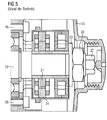
- FIG. 5 shows again a resolver with a known design.
- the resolver 21 is pressed onto a shaft 23 here.
- the resolver stator 24 or the resolver housing 25 is also fastened here with the aid of screws 26 on the end shield of the electrical machine.
- At the end of a hexagon 27 is incorporated in the shaft 23 to detect the exact rotational position of the shaft 23 and reach.
- the adjustment of the resolver or resolver rotor on the shaft 23 is also very troublesome here with the pressed Resolverrotor 21. Therefore, in a second embodiment, the resolver of FIG. 6 proposed.
- the Resolverrotor 31 shown there has an inner sleeve 311, with which it can be pressed onto a shaft. On the inside of this inner sleeve 311 extends in the axial direction a groove 312nd
- the resolver rotor 31 is surrounded by a resolver stator 34.
- a stator recess 341 can be seen on an end face of the resolver stator 34.
- This Statoraus originallyung 341 is rectangular in shape and has a certain axial extent.
- FIG. 7 a part of an assembly tool 39 is shown in perspective. It has a first rod 390, on the surface of which a raised guide 391 extends in the axial direction.
- the assembly tool 39 is a pressing tool and therefore has a compression sleeve 392, which is mounted axially displaceably on the first rod 390.
- the raised guide 391 slides into a groove 393 of the compression sleeve 392.
- a hexagon socket 394 is formed on the front side of the first rod 390.
- two further rods 395 and 396 are provided on the assembly tool 39 here. They have rectangular in the present example Cross section and are at the in FIG. 7 Not shown end connected to the first rod 390 so that they have a fixed position to each other.
- FIG. 8 to FIG. 11 Now the Aufpressvorgang the Resolverrotors 31 is shown on the end of a shaft 33.
- Resolver stator 34 is in FIG. 8 already attached with screws 36 on the bearing plate 30 of the electrical machine.
- a shoulder 331 can be seen, which constitutes a stop for the resolver rotor 31.
- a hexagon 332 is formed with a marking 333. This mark 333, for example, indicates a "center north pole" orientation of the rotor of the electric machine.
- the resolver stator 34 is to be aligned in the present example so that the radial direction, for example, the Statoraus Principleung 341 occupies a 90 ° angle with the radial direction of the marker 333.
- the two Statorausappel 341 and 342 lie in a horizontal plane, while the mark 333 points vertically upwards. In this state, the resolver is in the desired manner on the shaft 33 and the rotor of the electric machine aligned.
- FIG. 9 now shows a cross section through the part of the electrical machines with the resolver, wherein the central rod 390 of the mounting tool 39 on the end of the shaft 33, ie the hexagon 332 is placed.
- the resolver rotor 31 is axially displaceable on the first rod 390. Through the guide 391 in conjunction with its groove 312 it is secured against rotation.
- FIG. 10 It can be seen that the compression sleeve 392 of the mounting tool 39, the Resolverrotor 31 and its inner sleeve 311 pushes from the first rod 390 on the shaft 33 according to the arrows.
- FIG. 11 is the Aufpressvorgang finished. This can be seen from the fact that the sleeve 311 abuts the shaft shoulder 331 and is pushed completely by the first rod 390.
- the assembly tool 39 has caused with its hexagon socket 394 and its guide 391 that the resolver rotor 31 is aligned exactly with the shaft 33.
- the rigidly attached to the mounting tool further rods 395 and 396 cause the exact alignment of the resolver 34 in the direction of rotation relative to the resolver rotor 31 and the shaft 33. All three components (shaft 33, resolver rotor 31 and resolver 34) are thus adjusted to each other exactly, without that it requires a separate adjustment process after assembly.
- FIG. 12 shows a resolver in the delivery state. It has a resolver rotor 41 and a resolver stator 44. An end face 411 of the resolver rotor 41 is approximately flush with an end face 441 of the resolver stator 44. In the end face 411 two diametrically opposite Rotorausappelisme 412 and 413 are incorporated at the outer edge. Each of the two recesses 412 and 413 is associated with a StatorausEnglishung 441 and 442 opposite each other in the stator end face 440. It can be seen that the Statorausappelung 441 is slightly smaller than the Statorausappelung 442. The reason for this is again in the form of coding in order to achieve a clear positioning of the assembly tool can. The recesses 412, 413, 441 and 442 extend in the axial direction at a certain depth.
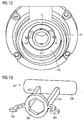
- FIG. 13 an assembly tool 49 is shown in perspective, which serves for the rotationally accurate plugging the resolver on a stub shaft.
- the assembly tool 49 has a handle 490. It is formed on two parallel rod-shaped webs 491 and 492, a ring 493 with a hexagon socket. Passage feet 494 and 495 are formed on two opposite sides of the ring 493. The right-hand foot 495 has a slightly larger foot area than the foot 494 for the purpose of shape coding.
- FIG. 14 is shown an oblique plan view of the front side of an electrical machine.
- the resolver 44 is fastened with screws 46 to the bearing plate 40 of the electric machine.
- Statorausappelisme 442 and 443 and the end of the shaft 43 with its frontal hexagon 432 and the mark 433 can be seen.
- FIG. 15 shows a section through the electric machine of FIG. 14 , wherein the resolver rotor 41 has already been slid almost completely onto the shaft 43 with the aid of the assembly tool 49.
- the resolver rotor 41 and the resolver stator 44 are not exactly opposite each other axially.
- the ring 493 is already pushed with its hexagon socket on the hexagon 432 of the shaft 43, so that the tool 49 assumes the desired rotational position relative to the shaft 43.
- the fitting feet 494 and 495 protrude into the rotor recesses 412 and 413, the resolver rotor 41 is also in the desired rotational position relative to the shaft 43.
- the fitting feet 494 and 495 of the mounting tool 49 also enter the stator recesses 441 and 442, whereby the resolver 44 is adjusted relative to the resolver rotor 41 and the shaft 43 with respect to its rotational position.
- This final assembly position is in a perspective view in FIG FIG. 16 shown. Since in the present example the resolver rotor 41 is not pressed onto the shaft 43 but is inserted only with little force, it is fastened on the shaft 43 with the aid of one or more setscrews 45. As a result, the resolver rotor 41 is secured against rotation and securely mounted against axial displacement on the shaft 43. After assembly, the assembly tool 49 is also withdrawn axially from the resolver or the shaft here.
Description
Die vorliegende Erfindung betrifft ein Verfahren zum Montieren eines Resolvers, der einen Resolverstator und einen Resolverrotor aufweist, auf einer Welle insbesondere einer elektrischen Maschine. Darüber hinaus betrifft die vorliegende Erfindung eine derartige elektrische Maschine.The present invention relates to a method for mounting a resolver comprising a resolver and a resolver rotor on a shaft, in particular an electric machine. Moreover, the present invention relates to such an electric machine.
Eine elektrische Maschine kann mit einem Resolver ausgestattet werden, um die Drehzahl oder die Drehposition der Welle der elektrischen Maschine zu bestimmen. Hierzu wird der Resolverstator üblicherweise an einem Lagerschild der elektrischen Maschine und der Resolverrotor an der Welle befestigt. Wichtig dabei ist, dass der Resolverrotor und damit die Welle gegenüber dem Resolverstator eine definierte Drehposition besitzt. Um dies zu gewährleisten, wird üblicherweise bei der Endprüfung einer elektrischen Maschine der Resolverstator gegenüber dem Resolverrotor dadurch justiert, dass der Resolverstator entsprechend verdreht wird. Diese Justage stellt jedoch im Rahmen der Endprüfung eine verhältnismäßig aufwendige Prozedur dar.An electric machine can be equipped with a resolver to determine the rotational speed or the rotational position of the shaft of the electric machine. For this purpose, the resolver is usually attached to a bearing plate of the electric machine and the resolver rotor to the shaft. It is important that the resolver rotor and thus the shaft has a defined rotational position relative to the resolver stator. To ensure this, usually in the final test of an electrical machine, the resolver is adjusted relative to the resolver rotor in that the resolver is rotated accordingly. However, this adjustment represents a relatively complex procedure in the final test.
Aus der
Aus der
Die Aufgabe der vorliegenden Erfindung besteht somit darin, das Justieren eines Resolvers an einer elektrischen Maschine zu vereinfachen.The object of the present invention is thus to simplify the adjustment of a resolver on an electrical machine.
Erfindungsgemäß wird diese Aufgabe gelöst durch ein Verfahren zum Montieren eines Resolvers, der einen Resolverstator und einen Resolverrotor aufweist, an einer Welle, durch Bereitstellen des Resolverstators mit mindestens einer axial ausgebildeten Statorausnehmung und Bereitstellen des Resolverrotors mit mindestens einer axial ausgebildeten Rotorausnehmung sowie Ausrichten der Statorausnehmung und der Rotorausnehmung in Rotationsrichtung zueinander, indem ein Montagewerkzeug zum Montieren des Resolvers mit einem jeweiligen Werkzeugabschnitt gleichzeitig in die Statorausnehmung und die Rotorausnehmung axial gesteckt wird.According to the invention, this object is achieved by a method for mounting a resolver, which has a resolver stator and a resolver rotor, on a shaft, by providing the resolver stator with at least one axially formed stator recess and providing the resolver rotor with at least one axially formed rotor recess and aligning the stator recess and the rotor recess in the rotational direction to each other by an assembly tool for mounting the resolver with a respective tool portion is inserted axially into the Statorausnehmung and the rotor recess simultaneously.
Darüber hinaus wird erfindungsgemäß bereitgestellt eine elektrische Maschine mit einer Welle und einem Resolver, der einen Resolverstator und einen Resolverrotor aufweist, wobei der Resolverstator mindestens eine Statorausnehmung und der Resolverrotor mindestens eine Rotorausnehmung aufweist, und die Statorausnehmung und die Rotorausnehmung axial ausgebildet sind, so dass ein Montagewerkzeug zum Montieren des Resolvers an die Welle mit einem jeweiligen Werkzeugabschnitt gleichzeitig in die Statorausnehmung und die Rotorausnehmung axial steckbar ist, um die Drehposition beider Resolverkomponenten zueinander genau festzulegen.In addition, the invention provides an electric machine with a shaft and a resolver, which has a resolver stator and a resolver rotor, wherein the resolver stator has at least one stator recess and the resolver rotor at least one rotor recess, and the stator recess and the rotor recess are formed axially, so that Assembly tool for mounting the resolver to the shaft with a respective tool portion at the same time in the Statorausnehmung and the rotor recess is axially plugged to exactly define the rotational position of both resolver components to each other.
In vorteilhafter Weise ist es durch die Ausnehmungen im Resolverstator und im Resolverrotor und das hierzu passende Montagewerkzeug möglich, die Drehposition beider Resolverkomponenten zueinander genau festzulegen. Damit kann eine Justage nach der Montage entfallen.Advantageously, it is possible through the recesses in Resolverstator and Resolverrotor and the fitting tool suitable for this purpose, the rotational position of both resolver components to each other exactly set. This eliminates an adjustment after assembly.
Gemäß einer Ausführungsform kann das Montagewerkzeug einen Hohlzylinder aufweisen, an dessen einer Stirnseite zwei unterschiedlich geformte Stifte axial abstehen, welche als die Werkzeugabschnitte in die Statorausnehmung und die Rotorausnehmung zum Ausrichten eingesteckt werden. Wenn die Ausnehmungen entsprechend negativ zu den Stiften geformt sind, kann dadurch eine Formcodierung erzielt werden, mit der die Drehpositionen von Resolverstator und Resolverrotor eindeutig zueinander festgelegt werden können.According to one embodiment, the assembly tool may comprise a hollow cylinder, on whose one end face two differently shaped pins project axially, which as the Tool sections are inserted into the Statorausnehmung and the rotor recess for aligning. If the recesses are formed correspondingly negative to the pins, thereby a shape coding can be achieved, with which the rotational positions of resolver and resolver rotor can be clearly set to each other.
Durch den Hohlzylinder des Montagewerkzeugs hindurch kann eine Schraube oder Mutter zur Befestigung des Resolverrotors in/auf die Welle geschraubt werden. Dadurch muss das Montagewerkzeug erst nach der endgültigen Befestigung des Resolverrotors auf der Welle und gegebenenfalls des Resolverstators an einem Lagerschild der elektrischen Maschine vom Resolver abgezogen werden.Through the hollow cylinder of the mounting tool through a screw or nut for mounting the resolver rotor can be screwed in / on the shaft. As a result, the assembly tool only after the final attachment of the resolver rotor on the shaft and possibly the Resolverstators on a bearing plate of the electric machine must be removed from the resolver.
In einer weiteren Ausführungsform kann das Montagewerkzeug ein Presswerkzeug sein, das eine Stange mit einer axial verlaufenden Führung und eine darauf axial geführte Hülse aufweist, wobei der Resolverrotor beim Aufpressen auf die Welle mit seiner Rotorausnehmung an der Führung axial geführt wird. Damit kann einem Presswerkzeug eine zusätzliche Funktion, nämlich die des Montagewerkzeugs zum Ausrichten der Resolverkomponenten zugeordnet werden.In a further embodiment, the assembly tool may be a pressing tool which has a rod with an axially extending guide and a sleeve guided axially thereon, wherein the resolver rotor is guided axially with its rotor recess on the guide when pressed onto the shaft. In this way, an additional function, namely that of the assembly tool for aligning the resolver components, can be assigned to a pressing tool.
Die Stange des Montagewerkzeugs kann so ausgebildet sein, dass es sich formschlüssig bzw. verdrehfest axial auf die Welle stecken lässt. Dadurch ist eine Montage mit eindeutiger Zuordnung der Resolverrotor-Drehposition zu der Wellen-Drehposition möglich.The rod of the assembly tool can be designed so that it can be stuck form fit or rotationally axially on the shaft. As a result, an assembly with a clear assignment of the resolver rotor rotational position to the shaft rotational position is possible.
Darüber hinaus kann das Montagewerkzeug mindestens eine zu der Stange parallele Ausrichtstange aufweisen, die beim Ausrichten in die Statorausnehmung gesteckt wird. Über die Stangen stellt das Montagewerkzeug eine eindeutige Beziehung zwischen Resolverstator und Resolverrotor hinsichtlich Drehposition her.In addition, the assembly tool can have at least one alignment rod which is parallel to the rod and which is inserted into the stator recess during alignment. About the rods, the assembly tool establishes a clear relationship between resolver and resolver rotor in terms of rotational position.
Gemäß einer anderen Ausführungsform ist vorgesehen, dass das Montagewerkzeug einen radial ausgerichteten Werkzeugabschnitt aufweist, die Rotorausnehmung und die Statorausnehmung jeweils stirnseitig am Resolverrotor und am Resolverstator ausgebildet sind, und der radial gerichtete Werkzeugabschnitt zum Ausrichten axial in die beiden Ausnehmungen gesteckt wird. Damit ist ein Ausrichten von Resolverrotor und Resolverstator auch möglich, wenn deren Stirnseiten in einer Ebene liegenAccording to another embodiment, it is provided that the assembly tool has a radially oriented tool portion, the rotor recess and the Statorausnehmung are each frontally formed on the resolver rotor and the resolver, and the radially directed tool portion is inserted axially into the two recesses for aligning. This alignment of the resolver rotor and resolver is also possible if their end faces lie in a plane
Wiederum kann das Montagewerkzeug ein Formschlusselement aufweisen, mit dem es verdrehsicher auf die Welle aufgesteckt wird. Insbesondere kann das Formschlusselement so ausgebildet sein, dass es nur in einer vorgegebenen Drehstellung auf die Welle aufsteckbar ist. Dadurch lässt sich wie in dem obigen Beispiel eine eindeutige Drehposition zwischen den Elementen Welle, Resolverstator und Resolverrotor festlegen.Again, the assembly tool may have a form-fitting element, with which it is mounted against rotation on the shaft. In particular, the interlocking element may be formed so that it can be plugged onto the shaft only in a predetermined rotational position. This can be as in the above Example: Define a definite rotational position between the elements shaft, resolver stator and resolver rotor.
Die vorliegende Erfindung wird nun anhand der beigefügten Zeichnungen näher erläutert, in denen zeigen:
- FIG 1
- einen Querschnitt durch einen montierten Resolver gemäß dem Stand der Technik;
- FIG 2
- einen Querschnitt durch einen Resolver gemäß einer ersten Ausführungsform;
- FIG 3
- eine perspektivische Ansicht eines Montagewerkzeugs für den Resolver von
FIG 2 ; - FIG 4
- einen Querschnitt durch den Resolver von
FIG 2 und das Montagewerkzeug vonFIG 3 im montieren Zustand; - FIG 5
- einen Querschnitt durch einen weiteren Resolver gemäß dem Stand der Technik;
- FIG 6
- einen Querschnitt durch einen Resolver gemäß einer zweiten Ausführungsform;
- FIG 7
- ein Montagewerkzeug für den Resolver von
FIG 6 ; - FIG 8
- eine Stirnseitenansicht einer elektrischen Maschine mit montiertem Resolverstator;
- FIG 9
- einen Querschnitt durch die elektrische Maschine von
FIG 8 mit angesetztem Resolverrotor; - FIG 10
- einen Ausschnitt von
FIG 9 beim Aufpressen des Resolverrotors; - FIG 11
- einen Querschnitt durch die elektrische Maschine mit vollständig aufgepresstem Resolverrotor;
- FIG 12
- einen Resolver gemäß einer dritten Ausführungsform;
- FIG 13
- ein Montagewerkzeug für den Resolver von
FIG 12 ; - FIG 14
- eine Stirnseitenansicht einer elektrischen Maschine mit dem montierten Resolverstator von
FIG 12 ; - FIG 15
- einen Querschnitt durch einen Teil der elektrischen Maschine von
FIG 14 mit nahezu vollständig aufgestecktem Resolverrotor und Montagewerkzeug und - FIG 16
- eine perspektivische Stirnseitenansicht der elektrischen Maschine von
FIG 15 .
- FIG. 1
- a cross section through a mounted resolver according to the prior art;
- FIG. 2
- a cross-section through a resolver according to a first embodiment;
- FIG. 3
- a perspective view of an assembly tool for the resolver of
FIG. 2 ; - FIG. 4
- a cross section through the resolver of
FIG. 2 and the assembly tool ofFIG. 3 in the assembled state; - FIG. 5
- a cross section through another resolver according to the prior art;
- FIG. 6
- a cross-section through a resolver according to a second embodiment;
- FIG. 7
- a mounting tool for the resolver of
FIG. 6 ; - FIG. 8
- an end view of an electric machine with mounted resolver;
- FIG. 9
- a cross section through the electric machine of
FIG. 8 with attached resolver rotor; - FIG. 10
- a section of
FIG. 9 when pressing on the resolver rotor; - FIG. 11
- a cross section through the electric machine with fully pressed Resolverrotor;
- FIG. 12
- a resolver according to a third embodiment;
- FIG. 13
- a mounting tool for the resolver of
FIG. 12 ; - FIG. 14
- an end view of an electric machine with the mounted resolver of
FIG. 12 ; - FIG. 15
- a cross section through a part of the electric machine of
FIG. 14 with almost completely attached Resolverrotor and mounting tool and - FIG. 16
- a perspective front view of the electrical machine of
FIG. 15 ,
Die nachfolgend näher geschilderten Ausführungsbeispiele stellen bevorzugte Ausführungsformen der vorliegenden Erfindung dar.The embodiments described in more detail below represent preferred embodiments of the present invention.
Zum besseren Verständnis der ersten Ausführungsform wird zunächst anhand des Querschnitts von
Daher wird gemäß einer ersten Ausführungsform ein Resolver bereitgestellt, der anhand der
Der Resolverstator 14 bzw. dessen Gehäuse besitzt stirnseitig zwei Statorausnehmungen 141 und 142. Diese beiden Statorausnehmungen 141, 142 fluchten axial mit den Rotorausnehmungen 115, 116. Die Statorausnehmung 142 hat den gleichen Durchmesser wie die Rotorausnehmung 115 und die Statorausnehmung 141 hat den gleichen Durchmesser wie die Rotorausnehmung 116.The
Mit Hilfe des Montagewerkzeugs 9 kann so die gesamte Resolvereinheit 11, 14 in einer bestimmten Drehposition an die Welle 13 montiert werden und es ist dabei die relative Drehposition von Resolverrotor und Resolverstator zueinander von vorneherein festgelegt. Eine nachträgliche Justage dieser Komponenten kann also entfallen. Nach der Montage wird das Montagewerkzeug 19 vom Resolver axial abgezogen.With the aid of the assembly tool 9, the
Nachfolgend wird im Zusammenhang mit den
Die Justage von Resolverstator bzw. Resolverrotor an der Welle 23 ist auch hier bei dem aufgepressten Resolverrotor 21 sehr mühsam. Daher wird in einer zweiten Ausführungsform der Resolver von
Umgeben ist der Resolverrotor 31 von einem Resolverstator 34. An einer Stirnfläche des Resolverstators 34 ist eine Statorausnehmung 341 zu erkennen. Diese Statorausnehmung 341 ist hier rechteckförmig ausgebildet und besitzt eine gewisse axiale Erstreckung.The
In
In den
In die Statorausnehmungen 341 und 342 sind die Stäbe 395 und 396 des Montagewerkzeugs 39 eingesteckt. Insgesamt ist der Resolverstator 34 im vorliegenden Beispiel so auszurichten, dass die radiale Richtung beispielsweise der Statorausnehmung 341 mit der radialen Richtung der Markierung 333 einen 90°-Winkel einnimmt. Im vorliegenden Beispiel liegen die beiden Statorausnehmungen 341 und 342 in einer horizontalen Ebene, während die Markierung 333 vertikal nach oben weist. In diesem Zustand ist der Resolver in hier gewünschter Weise auf die Welle 33 bzw. den Rotor der elektrischen Maschine ausgerichtet.In the
In
In
Ein drittes Ausführungsbeispiel wird nun anhand der
In
In
Diese Endmontageposition ist in einer perspektivischen Ansicht in
In vorteilhafter Weise ist bei den oben genannten Ausführungsformen eine Zusammenführung von Resolver-Umbauteilen möglich, wodurch die Verwendung einer Vorjustage-Vorrichtung bei der Montage möglich wird und somit die Justage in der Endprüfung entfallen kann.Advantageously, in the above embodiments, a combination of resolver conversion parts is possible, whereby the use of a Vorjustage device during assembly is possible and thus can account for the adjustment in the final test.
Claims (14)
- Method for fitting a resolver comprising a resolver stator (4, 14, 24, 34, 44) and a resolver rotor (1, 11, 21, 31, 41) to a shaft (3, 13, 23, 33, 43),
characterised by- providing the resolver stator (4, 14, 24, 34, 44) with at least one axially embodied stator recess (141, 142, 341, 342, 441, 442) and- providing the resolver rotor (1, 11, 21, 31, 41) with at least one axially embodied rotor recess (115, 116, 312, 412, 413) and- aligning the stator recess (141, 142, 341, 342, 441, 442) and the rotor recess (115, 116, 312, 412, 413) relative to one another in the direction of rotation, by an assembly tool (19, 39, 49) for fitting the resolver with a respective tool section (191, 192, 391, 395, 396, 494, 495) being axially inserted into the stator recess (141, 142, 341, 342, 441, 442) and the rotor recess (115, 116, 312, 412, 413) at the same time. - Method according to claim 1, wherein the assembly tool (19, 39, 49) comprises a hollow cylinder (190), at a front face of which two pins (191, 192) protrude axially, which, as the tool sections, are introduced into the stator recess (141, 142, 341, 342, 441, 442) and the rotor recess (115, 116, 312, 412, 413) for alignment purposes.
- Method according to claim 2, wherein a screw (12) or nut for fastening the resolver rotor (1, 11, 21, 31, 41) into/onto the shaft (3, 13, 23, 33, 43) is screwed through the hollow cylinder (190) of the assembly tool (19, 39, 49).
- Method according to claim 1, wherein the assembly tool (19, 39, 49) is a pressing tool, which has a rod (390) with an axially running guidance (391) and a sleeve (392) guided axially thereupon, and wherein the resolver rotor (1, 11, 21, 31, 41) is axially guided with its rotor recess (115, 116, 312, 412, 413) on the guidance (391) when being pressed onto the shaft (3, 13, 23, 33, 43).
- Method according to claim 4, wherein the rod (390) is axially inserted in a form-fit manner onto the shaft (3, 13, 23, 33, 43).
- Method according to claim 4 or 5, wherein the assembly tool (19, 39, 49) comprises at least one alignment rod (395, 396) in parallel with the rod (390), which alignment rod (395, 396) is inserted into the stator recess (141, 142, 341, 342, 441, 442) during the alignment process.
- Method according to claim 1, wherein the assembly tool (19, 39, 49) comprises a radially aligned tool section (494, 495), the rotor recess (115, 116, 312, 412, 413) and the stator recess (141, 142, 341, 342, 441, 442) are each embodied at the front face on the resolver rotor (1, 11, 21, 31, 41) and on the resolver stator (4, 14, 24, 34, 44) and the radially aligned tool section (494, 495) is axially inserted into both recesses for alignment purposes.
- Method according to claim 7, wherein the assembly tool (19, 39, 49) comprises a form-fit element (394, 493) with which it is inserted onto the shaft (3, 13, 23, 33, 43) in an anti-twist manner.
- Method according to claim 8, wherein the form-fit element (394, 493) can only be attached to the shaft (3, 13, 23, 33, 43) in a predetermined rotational position.
- Method according to one of the preceding claims, wherein after fastening the resolver rotor (1, 11, 21, 31, 41) to the shaft (3, 13, 23, 33, 43) and the resolver stator (4, 14, 24, 34, 44) on a bearing shield (10, 30, 40) or housing of the electrical machine, the assembly tool (19, 39, 49) is axially detached from the resolver.
- Electrical machine having- a shaft (3, 13, 23, 33, 43) and- a resolver comprising a resolver stator (4, 14, 24, 34, 44) and a resolver rotor (1, 11, 21, 31, 41),
characterised in that- the resolver stator (4, 14, 24, 34, 44) comprises at least one stator recess (141, 142, 341, 342, 441, 442) and the resolver rotor (1, 11, 21, 31, 41) comprises at least one rotor recess (115, 116, 312, 412, 413), and- the stator recess (141, 142, 341, 342, 441, 442) and the rotor recess (115, 116, 312, 412, 413) are embodied axially such that- an assembly tool (19, 39, 49) for fixing the resolver on the shaft (3, 13, 23, 33, 43) can be axially inserted into the stator recess (141, 142, 341, 342, 441, 442) and the rotor recess (115, 116, 312, 412, 413) at the same time using a respective tool section (191, 192, 391, 395, 396, 494, 495) in order to accurately define the rotational position of both resolver components relative to one another. - Electrical machine according to claim 11, wherein the assembly tool (19, 39, 49) is attached to the resolver and comprises a hollow cylinder (190), on a front face of which two pins (191, 192) protrude axially, which, as the tool sections, are introduced into the stator recess (141, 142, 341, 342, 441, 442) and the rotor recess (115, 116, 312, 412, 413) for alignment purposes.
- Electrical machine according to claim 11, wherein the assembly tool (19, 39, 49) is attached to the resolver and represents a pressing tool comprising a rod (390) with an axially running guidance (391) and a sleeve (392) axially guided thereupon, and wherein the resolver rotor (1, 11, 21, 31, 41) is axially guided in the guidance (391) with its rotor recess (115).
- Electrical machine according to claim 11, wherein the assembly tool (19, 39, 49) is attached to the resolver and comprises a radially aligned tool section (494, 495), the rotor recess (115, 116, 312, 412, 413) and the stator recess (141, 142, 341, 342, 441, 442) are embodied in each instance at the front face on the resolver rotor (1, 11, 21, 31, 41) and on the resolver stator (4, 14, 24, 34, 44) and the radially aligned tool section (494, 495) is inserted into both recesses so as to be axially removable.
Priority Applications (1)
| Application Number | Priority Date | Filing Date | Title |
|---|---|---|---|
| EP08171368.7A EP2197092B1 (en) | 2008-12-11 | 2008-12-11 | Method for fitting a resolver and electrical machine |
Applications Claiming Priority (1)
| Application Number | Priority Date | Filing Date | Title |
|---|---|---|---|
| EP08171368.7A EP2197092B1 (en) | 2008-12-11 | 2008-12-11 | Method for fitting a resolver and electrical machine |
Publications (2)
| Publication Number | Publication Date |
|---|---|
| EP2197092A1 EP2197092A1 (en) | 2010-06-16 |
| EP2197092B1 true EP2197092B1 (en) | 2013-05-01 |
Family
ID=40793268
Family Applications (1)
| Application Number | Title | Priority Date | Filing Date |
|---|---|---|---|
| EP08171368.7A Expired - Fee Related EP2197092B1 (en) | 2008-12-11 | 2008-12-11 | Method for fitting a resolver and electrical machine |
Country Status (1)
| Country | Link |
|---|---|
| EP (1) | EP2197092B1 (en) |
Cited By (1)
| Publication number | Priority date | Publication date | Assignee | Title |
|---|---|---|---|---|
| DE102022103725A1 (en) | 2022-02-17 | 2023-08-17 | HELLA GmbH & Co. KGaA | Method, system, housing and circuit board for manufacturing a rotation angle sensor unit |
Families Citing this family (2)
| Publication number | Priority date | Publication date | Assignee | Title |
|---|---|---|---|---|
| WO2013174405A1 (en) * | 2012-05-24 | 2013-11-28 | Baumüller Nürnberg GmbH | Electrical machine |
| DE102022004471A1 (en) | 2021-12-20 | 2023-06-22 | Sew-Eurodrive Gmbh & Co Kg | Electric motor with angle sensor |
Family Cites Families (4)
| Publication number | Priority date | Publication date | Assignee | Title |
|---|---|---|---|---|
| US4888509A (en) | 1988-02-05 | 1989-12-19 | Jaroslav Tomasek | Brushless servo motor construction and alignment |
| US5061868A (en) * | 1989-09-25 | 1991-10-29 | Nippon Densan Corporation | Spindle motor |
| DE102004056990B4 (en) * | 2004-11-25 | 2007-04-12 | Minebea Co., Ltd. | Electric machine, in particular brushless DC motor, and method for adjusting a sensor unit in an electric machine |
| DE102007013049A1 (en) | 2007-03-19 | 2008-09-25 | Siemens Ag | Method for mounting an angle measuring device on an electric motor |
-
2008
- 2008-12-11 EP EP08171368.7A patent/EP2197092B1/en not_active Expired - Fee Related
Cited By (1)
| Publication number | Priority date | Publication date | Assignee | Title |
|---|---|---|---|---|
| DE102022103725A1 (en) | 2022-02-17 | 2023-08-17 | HELLA GmbH & Co. KGaA | Method, system, housing and circuit board for manufacturing a rotation angle sensor unit |
Also Published As
| Publication number | Publication date |
|---|---|
| EP2197092A1 (en) | 2010-06-16 |
Similar Documents
| Publication | Publication Date | Title |
|---|---|---|
| EP1941597A1 (en) | Rotor for an electrical machine | |
| EP2688709B1 (en) | Method, tool and machine and for calibrating bushings | |
| EP3156666B1 (en) | Fastening system for a machine element | |
| EP1821395A2 (en) | Method for adjusting a braking torque and magnetic hysteresis brake | |
| DE102010020355A1 (en) | Device for locking drive train of wind power plant, has locking bolt engaged in locking opening, and mounting element provided in curved slot and fixing position of locking unit in curved slot in stepless manner | |
| DE3300414C2 (en) | ||
| EP2197092B1 (en) | Method for fitting a resolver and electrical machine | |
| EP3053253B1 (en) | Electric motor | |
| EP2881604B1 (en) | Fastening device for concentric fixing of a shaft on an encoder shaft and motor feedback system with such fastening | |
| EP2495463B1 (en) | Linear unit with tubular system | |
| DE102012108031A1 (en) | Holder for a joining device | |
| EP0412954B1 (en) | Bearing shield for an electric motor | |
| EP0263476A2 (en) | Method for aligning a pallet on a machine tool table, and aligning piece therefor | |
| EP1749929A2 (en) | Device for producing or treating a web of material, in particular a paper or board web | |
| EP0087623A1 (en) | Method of manufacturing a double-nut running on a threaded spindle | |
| DE3307952A1 (en) | ELECTRIC MOTOR | |
| DE102014103138B4 (en) | Lathe broaching machine | |
| DE2604874A1 (en) | PASS SYSTEM FOR OFFSET ROLL ROTARY PRINTING MACHINES | |
| DE102005014808B4 (en) | measuring device | |
| DE19600071C1 (en) | Side register system for plate cylinder | |
| EP2669050B1 (en) | Tool, system and method for the screwing of helical compression springs to a screw plate spring | |
| EP2424083B1 (en) | Electric motor and method for its production | |
| AT505361B1 (en) | TOOL HOLDERS AND METHOD FOR ORIENTING TOOL MOUNTS AT THE TOOL HOLDER | |
| DE2626155A1 (en) | Blank positioning device for machine tool - has honeycomb plate with bushes secured in bores by hardening material | |
| EP3334908B1 (en) | Method and device for assembling an adjustable camshaft |
Legal Events
| Date | Code | Title | Description |
|---|---|---|---|
| PUAI | Public reference made under article 153(3) epc to a published international application that has entered the european phase |
Free format text: ORIGINAL CODE: 0009012 |
|
| 17P | Request for examination filed |
Effective date: 20090907 |
|
| AK | Designated contracting states |
Kind code of ref document: A1 Designated state(s): AT BE BG CH CY CZ DE DK EE ES FI FR GB GR HR HU IE IS IT LI LT LU LV MC MT NL NO PL PT RO SE SI SK TR |
|
| AX | Request for extension of the european patent |
Extension state: AL BA MK RS |
|
| AKX | Designation fees paid |
Designated state(s): DE |
|
| GRAP | Despatch of communication of intention to grant a patent |
Free format text: ORIGINAL CODE: EPIDOSNIGR1 |
|
| RAP1 | Party data changed (applicant data changed or rights of an application transferred) |
Owner name: SIEMENS AKTIENGESELLSCHAFT |
|
| GRAS | Grant fee paid |
Free format text: ORIGINAL CODE: EPIDOSNIGR3 |
|
| GRAA | (expected) grant |
Free format text: ORIGINAL CODE: 0009210 |
|
| AK | Designated contracting states |
Kind code of ref document: B1 Designated state(s): DE |
|
| REG | Reference to a national code |
Ref country code: DE Ref legal event code: R096 Ref document number: 502008009834 Country of ref document: DE Effective date: 20130704 |
|
| PLBE | No opposition filed within time limit |
Free format text: ORIGINAL CODE: 0009261 |
|
| STAA | Information on the status of an ep patent application or granted ep patent |
Free format text: STATUS: NO OPPOSITION FILED WITHIN TIME LIMIT |
|
| 26N | No opposition filed |
Effective date: 20140204 |
|
| REG | Reference to a national code |
Ref country code: DE Ref legal event code: R097 Ref document number: 502008009834 Country of ref document: DE Effective date: 20140204 |
|
| PGFP | Annual fee paid to national office [announced via postgrant information from national office to epo] |
Ref country code: DE Payment date: 20180219 Year of fee payment: 10 |
|
| REG | Reference to a national code |
Ref country code: DE Ref legal event code: R119 Ref document number: 502008009834 Country of ref document: DE |
|
| PG25 | Lapsed in a contracting state [announced via postgrant information from national office to epo] |
Ref country code: DE Free format text: LAPSE BECAUSE OF NON-PAYMENT OF DUE FEES Effective date: 20190702 |