EP2360307B1 - Machine à laver à tambour - Google Patents
Machine à laver à tambour Download PDFInfo
- Publication number
- EP2360307B1 EP2360307B1 EP11003991A EP11003991A EP2360307B1 EP 2360307 B1 EP2360307 B1 EP 2360307B1 EP 11003991 A EP11003991 A EP 11003991A EP 11003991 A EP11003991 A EP 11003991A EP 2360307 B1 EP2360307 B1 EP 2360307B1
- Authority
- EP
- European Patent Office
- Prior art keywords
- drum
- tub
- washing machine
- foreign matter
- opening
- Prior art date
- Legal status (The legal status is an assumption and is not a legal conclusion. Google has not performed a legal analysis and makes no representation as to the accuracy of the status listed.)
- Ceased
Links
- 238000005406 washing Methods 0.000 title claims description 58
- 239000013013 elastic material Substances 0.000 claims description 5
- 239000000725 suspension Substances 0.000 claims description 3
- 230000003449 preventive effect Effects 0.000 description 22
- 238000013016 damping Methods 0.000 description 10
- XLYOFNOQVPJJNP-UHFFFAOYSA-N water Substances O XLYOFNOQVPJJNP-UHFFFAOYSA-N 0.000 description 6
- 238000009987 spinning Methods 0.000 description 5
- 239000011248 coating agent Substances 0.000 description 3
- 238000000576 coating method Methods 0.000 description 3
- 238000007789 sealing Methods 0.000 description 3
- 230000005540 biological transmission Effects 0.000 description 1
- 239000003599 detergent Substances 0.000 description 1
- 238000010586 diagram Methods 0.000 description 1
- 230000008595 infiltration Effects 0.000 description 1
- 238000001764 infiltration Methods 0.000 description 1
- 239000007788 liquid Substances 0.000 description 1
- 239000000463 material Substances 0.000 description 1
- 238000002360 preparation method Methods 0.000 description 1
- 239000000126 substance Substances 0.000 description 1
Images


Classifications
-
- D—TEXTILES; PAPER
- D06—TREATMENT OF TEXTILES OR THE LIKE; LAUNDERING; FLEXIBLE MATERIALS NOT OTHERWISE PROVIDED FOR
- D06F—LAUNDERING, DRYING, IRONING, PRESSING OR FOLDING TEXTILE ARTICLES
- D06F37/00—Details specific to washing machines covered by groups D06F21/00 - D06F25/00
- D06F37/02—Rotary receptacles, e.g. drums
- D06F37/04—Rotary receptacles, e.g. drums adapted for rotation or oscillation about a horizontal or inclined axis
-
- D—TEXTILES; PAPER
- D06—TREATMENT OF TEXTILES OR THE LIKE; LAUNDERING; FLEXIBLE MATERIALS NOT OTHERWISE PROVIDED FOR
- D06F—LAUNDERING, DRYING, IRONING, PRESSING OR FOLDING TEXTILE ARTICLES
- D06F37/00—Details specific to washing machines covered by groups D06F21/00 - D06F25/00
- D06F37/26—Casings; Tubs
- D06F37/266—Gaskets mounted between tub and casing around the loading opening
-
- D—TEXTILES; PAPER
- D06—TREATMENT OF TEXTILES OR THE LIKE; LAUNDERING; FLEXIBLE MATERIALS NOT OTHERWISE PROVIDED FOR
- D06F—LAUNDERING, DRYING, IRONING, PRESSING OR FOLDING TEXTILE ARTICLES
- D06F37/00—Details specific to washing machines covered by groups D06F21/00 - D06F25/00
- D06F37/02—Rotary receptacles, e.g. drums
- D06F37/04—Rotary receptacles, e.g. drums adapted for rotation or oscillation about a horizontal or inclined axis
- D06F37/06—Ribs, lifters, or rubbing means forming part of the receptacle
Definitions
- the present invention relates to washing machines, and more particularly, to a washing machine which can maximize a volume within a cabinet, attenuate vibration, and prevent foreign matters from entering into between a drum and a tub.
- FIG. 1 illustrates a section of a related art washing machine
- FIG. 2 illustrates a section along a line II-II in FIG. 1 .
- the related art drum type washing machine is provided with a cabinet or housing 1 having a base 1a and a door 1b, a tub 2 fixedly secured inside of the cabinet 1, a drum 3 rotatably mounted inside of the tub 2 for rotating laundry m and washing water by means of lifts 3a, a motor 4 for rotating the drum 3, and springs 5, dampers 6, and balancers 7 for attenuating vibration transmitted to the tub 2.
- the drum 3 has a plurality of holes 3b for flow of the washing water from the tub 2 to the drum 3.
- the lifts 3a are formed on an inside surface of the drum 3, so that the lifts 3a, rotating together with the drum 3, move the laundry m loaded in the drum 3, together with the washing water.
- the tub 2 is mounted spaced a predetermined distance away from an inside surface of the cabinet 1, suspended from an inside of the cabinet 1 with the springs 5 secured to opposite sides of an upper side of the tub 2, and dampers 6 are connected to the tub 2 and the base 1a with hinges and supported on the base 1a, so that the springs 5 and the dampers 6 attenuate the vibration from the tub 2 to the cabinet 1.
- the door 1b on the cabinet 1 is rotatably mounted to a front 1d of the cabinet 1 for introduction of the laundry m thereto, and fronts 2d and 3d of the tub 2 and the drum 3 respectively have openings 2c and 3c so that the tub 2 and the drum 3 are in communication with an opening which is opened and closed by the door 1b
- a gasket 8 mounted between the front 1d of the cabinet 1 having the door 1 thereon and the front 2d of the tub 2, there is a gasket 8 for preventing the washing water from leaking, by sealing a gap between the inside of the cabinet 1 and the front 2d of the tub 2.
- the motor 4 on a rear surface of the tub 2, rotates the drum 3 in the tub 2.
- the balancer 7 is mounted to, and balances the drum 3.
- the balancer 7 of a predetermined weight provides centrifugal force to the drum 3 rotating at a high speed in spinning, to attenuate vibration of the drum 3.
- the related art drum type washing machine has a problem in that a volume of the cabinet or housing 1 is excessively large in comparison to the volume of the drum 3 in which washing is performed.
- the volume of the drum 3 is reduced when the sizes of the cabinets 1 are the same.
- the washing machine further comprises a housing, a tub mounted inside of the housing, wherein the tub has an opening through which laundry is inserted and removed, and a drum rotatably mounted inside of the tub, wherein the drum has an opening through which laundry is inserted and removed.
- the washing machine further includes a laundry shield that is mounted to the tub and comprises a portion which is disposed between an edge of the opening of the drum and a sealing member located between the housing and the tub, wherein the portion of the laundry shield extends radially inward with respect to a rotational axis direction of the drum so as to overlap with the edge of the opening of the drum.
- the radially extended portion includes a bent portion, which extends in the rotational axis direction and then extends radially outward with respect to the rotational axis direction.
- the laundry shield has a U-shaped portion overlapping with the edge of the opening of the drum.
- the present invention is directed to a washing machine.
- An object of the present invention is to provide a washing machine which can maximize a volume of a drum for cabinets of the same size.
- Another object of the present invention is to provide a washing machine in which infiltration of foreign matters between a tub and a drum can be prevented.
- a washing machine includes the features of claim 1.
- a washing machine includes a housing which forms an exterior of the washing machine; a tub mounted inside of the housing, the tub having an opening through which laundry may be inserted and removed; a drum rotatably mounted inside of the tub, the drum having an opening substantially aligned with the opening of the tub, through which laundry may be inserted and removed; and a foreign matter shield configured to prevent foreign matter from entering a space between the tub and the drum by maintaining a gap between the opening of the drum and the tub at a predetermined size during movement of the drum relative to the tub from an initial position to a lower position.
- the foreign matter shield may include a catch-space configured to hold foreign matter to prevent foreign matter introduced through the gap between the opening of the drum and the tub from entering into a space between an outer circumferential surface of the drum and an inner circumferential surface of the tub.
- the foreign matter shield may be configured to cover an area which the opening of the drum traverses during upward and downward movement of the drum. A predetermined distance may be maintained between the foreign matter shield and the opening of the drum during upward and downward movement of the drum.
- the foreign matter shield may be formed of an elastic material.
- the washing machine may further include a drum guide extending from the opening of the drum toward the foreign matter shield.
- the foreign matter shield may comprise a first rib extending from an inner circumferential surface of the opening of the tub toward the opening of the drum; and a second rib extending a predetermined distance from the first rib toward an outer circumferential surface of the tub for maintaining a gap between the opening of the drum and the tub at a predetermined size during movement of the drum relative to the tub from an initial position to a lower position.
- the first rib may be formed along the inner circumferential surface of the opening of the tub.
- the second rib may be formed at least partially within an extent of the first rib.
- the second rib may include a side which faces the drum and is configured to cover an area which the opening of the drum traverses during upward and downward movement of the drum. A predetermined distance may be maintained between the side of the second rib which faces the drum and the opening of the drum during upward and downward movement of the drum.
- the second rib may include at least a portion which contacts and is supported by the tub.
- the second rib may include a catch-space configured to hold foreign matter introduced between the first rib and the opening of the drum.
- the catch-space of the second rib may have a drain hole for draining washing water from the catch-space.
- the second rib may include a friction reduction coating that reduces friction during contact between the second rib and the drum.
- the second rib may be formed of an elastic material.
- the washing machine may further include a drum guide extending from the opening of the drum toward the first rib.
- FIG. 1 is a sectional view illustrating a related art washing machine, schematically.
- FIG. 2 is a sectional view illustrating a section across a line II-II in FIG. 2 ;
- FIG. 3 is a sectional view illustrating a washing machine in accordance with a first embodiment of the present invention
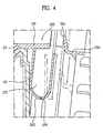
- FIG. 4 is an enlarged sectional view illustrating a portion of FIG. 3 ;
- FIG. 5 is a front view illustrating the foreign matter entering preventive device in FIG. 3 ;
- FIG. 6 is a sectional view illustrating a foreign matter entering preventive device in accordance with an embodiment useful for the understanding of the present invention.
- FIG. 7 is a sectional view illustrating a foreign matter entering preventive device in accordance with a second embodiment of the present invention.
- FIGS. 3 and 4 illustrate diagrams of drum type washing machines in accordance with preferred embodiments of the present invention, respectively.
- the drum type washing machine of the present invention includes a cabinet or housing 10 which forms an exterior of the drum type washing machine, a tub 20 fixedly secured to an inside of the cabinet 10 directly, a drum 30 rotatably mounted to an inside of the tub 20, a motor 40 in rear of the tub 20 for rotating the drum 30, a bearing housing 28 forming a rear of the tub 20 and supporting a shaft 42 of the motor 40, damping device or element 50 between the bearing housing 28 and the tub 20 for sealing the inside of the tub 20 and damping vibration or impact from the motor 40 to the tub 20, and a suspension assembly 60 for supporting the drum 30 and attenuating the vibration or impact to the bearing housing 28.
- the cabinet or housing 10 has a laundry opening in a front 11 for introduction of laundry, with a door 12 mounted thereto for opening/closing the laundry opening.
- a base 16 of the cabinet 10 which forms a bottom surface of the cabinet 10.
- the tub 20 is fixedly secured to the inside of the cabinet 10 directly.
- a side of the tub 20 facing the door 12 may be fixedly secured to an inside of the front 11 of the cabinet 10 in any suitable manner, such as fastened with screws 25.
- sides or a rear of the tub 20 may be fixedly secured to the cabinet 10.
- the tub 20 has a laundry opening 22 in a front adjacent to the door for introduction of the laundry.
- top bracket 73 on an upper side of the cabinet 10 for securing an elastic member 72 thereto, which suspends the bearing housing.
- the bearing housing 28 is fixedly secured to the rear of the tub 20.
- the bearing housing 28 is provided with bearings (not shown) for supporting, and smooth rotation of, the motor shaft 42.
- the damping device 50 is formed of an elastic material that contracts, or relaxes according to the vibration or the impact, for damping transmission of vibration or impact from the drum 30 and the motor 40 to the tub 20 during washing or spinning.
- the motor 40 is fixedly secured to a rear side of the bearing housing 28, with a motor shaft 42 passed through the bearing housing 28 and fixed to a rear side of the drum 30.
- the drum 30 is rotated by the motor shaft 42 and has lifts 32 on an inside surface for moving the laundry during rotation of the drum 30.
- the suspension assembly 60 includes a damper bracket 62 fixed to the bearing housing 28, and a damping unit coupled to the damper bracket 62 for supporting the bearing housing 28.
- the damping unit may include a main damper 80 for supporting weight of the drum 30 and damping vertical direction vibration of the drum 30, and a sub-damper 90 for damping horizontal direction vibration of the drum 30.
- the washing machine of the embodiment can enlarge a diameter of the tub 20, allowing volumes of the tub 20 and the drum 30 to be enlarged.
- the drum 30 is supported only on one side, the volume of the drum 30 can be enlarged further compared to a type in which the drum 30 is supported on both sides. Since a number of components can be reduced as in this manner, improvement in productivity can be achieved.
- the tub 20 is fixedly secured to the cabinet 10, if vibration or impact is applied to the tub 20 which is fixedly secured to the cabinet 10 as one unit, the tub 20 by itself is not shaken by the vibration or impact, but because a weight of the cabinet 10 is added to a weight of the tub 20, and increases stiffness or rigidity of the tub 20, an overall vibration characteristic of the drum type washing machine can be improved.
- a predetermined gap is provided between the tub 20 and the drum 30 so that the drum 30 does not come into contact with the drum 20 when the drum 30 vibrates.
- foreign matter such as coins or buttons
- the foreign matter are likely to hit the drum 30 to cause noise, and further, when the drum 30 spins at a high speed, the tub 20 or the drum 30 can be damaged.
- the washing machine in accordance with a preferred embodiment of the present invention includes a foreign matter entering preventive device or shield 100 for preventing foreign matter from entering between the tub 20 and the drum 30 by making the gap between the opening 36 of the drum 30 and the tub to be maintained even if the drum 30 moves down by the weight of the laundry.
- the foreign matter entering preventive device or shield 100 may include a first rib 110 provided at the opening of the tub 20, and a second rib 120 extended from the first rib 110 toward an outside circumference of the tub 20.
- FIG. 4 is an enlarged sectional view illustrating the foreign matter entering preventive device 100.
- the first rib 110 may be formed along an inside circumference of the laundry opening 22 of the tub 20, extended toward an inside of the tub 20 by a predetermined length.
- the second rib 120 is extended from the first rib 110 toward an outside circumference of the tub 20 by a predetermined length to form a free end.
- the gap between the second rib 120 and the opening 36 of the drum is small enough to prevent the foreign matters from entering.
- the first rib 110 maintains the gap between the edge 36a of the opening of the drum and the first rib 110, to prevent the foreign matters from entering therebetween.
- the second rib 120 maintains the gap between the edge 36a of the opening of the drum and the second rib 120 even when the drum 30 moves down by the weight of the laundry, to prevent the foreign matter from entering therebetween. This will be described in more detail hereafter.
- the foreign matter may be a hard substance, such as coins and buttons in the laundry, which, if located between the tub 20 and the drum 30, are likely to cause noise or damage during washing.
- the gap between the foreign matter entering preventive device or shield 100 and the edge 36a of the opening of the drum is provided for preventing the foreign matter entering preventive device or shield 100 from being brought into contact with the drum 30 when the drum 30 rotates.
- the second rib 120 or the foreign matter entering preventive device or shield 100 is formed of an elastic material which enables deformation and restoration, for preventing the second rib 120 or the foreign matter entering preventive device or shield 100 from being damaged by the impact caused by collision with the drum 30.
- a suitable friction preventive coating may be applied to a surface of the second rib 120 facing the edge 36a of the opening of the drum for minimizing friction when the second rib 120 is in contact with the drum.
- the second rib 120 or the foreign matter entering preventive device 100 itself may be formed of a material having a low friction coefficient.
- the second rib 120 deforms excessively at the time the drum 30 is brought into contact, or collides, with the second rib 120, since the excessive deformation is liable to break the second rib 120 or affect the first rib 110, it is preferable that the second rib 120 is formed such that a portion thereof can be supported by an inside surface of the tub 20 when the second rib 120 comes into contact with the tub 20 for preventing the second rib 120 from deforming excessively.
- the second rib 120 is formed in conformity with a locus the edge 36a of the opening of the drum forms at the time the drum 30 moves down, with a predetermined gap to the locus. In this manner, the second rib 120 covers an area which the opening of the drum traverses during upward and downward movement of the drum.
- the gap is small enough to prevent the foreign matter from falling down therebetween.
- the second rib 120 has a length at least as long as a moving up/down distance of the drum 30. If the second rib 120 has a length shorter than the moving up/down distance of the drum 30, a distance between the second rib 120 and the edge 36a of the opening of the drum will become greater when the drum 30 moves beyond the second rib 120, permitting the foreign matter to enter therebetween.
- the second rib 120 may be formed at least on a portion of the outside circumference of the first rib 110.
- the second rib 120 may be formed throughout the outside circumference of the first rib 110, or only on a portion of the outside circumference of the first rib 110.
- the second rib 120 when the second rib 120 is formed only on a portion of the first rib 110, it is preferable that the second rib 120 is formed at a portion excluding an upper portion of the first rib 110.
- first rib 110 extends toward the drum 30, foreign matter with sizes smaller than the gap between the first rib 110 and the edge 36a of the opening of the drum may fall between the first rib 110 and the edge 36a of the opening of the drum.
- the second rib 120 may have a U-bent portion to form a holding space or catch-space 122 for holding the foreign matter.
- the holding space or catch-space 122 has a side facing the drum 30 having the predetermined gap to the locus the edge 36a of the opening of the drum forms when the drum 30 moves down.
- a friction preventive coating may be applied to the side of the holding space 122 facing the drum 30, a portion of the holding space 122 may be in contact with the inside surface of the tub 20 for preventing the second rib 120 from deforming excessively, and reducing impact caused when the drum 30 comes into contact with the second rib 120 transmitted to the first rib 110.
- the drum 30 and the second rib 120 are configured so that the impact caused by the contact of the drum 30 can be absorbed by deformation of the bent portion of the holding space 122 of the second rib 120 and the side of the drum 30 facing the opening 36.
- the holding space 122 formed on at least a portion of the second rib 120 captures the foreign matter shooting out of the drum 30 in a circumferential direction of the drum 30 by rotation force of the drum 30 during the drum 30 rotation, thereby preventing the foreign matter from entering between the tub 20 and the drum 30.
- a drain hole 126 is formed in a bottom of the holding space for draining washing water introduced therein into the tub 20.
- a drum guide 130 may further be provided, which is extended from the opening 36 of the drum 30 toward an inside circumference of the laundry opening 22 of the tub 20 for preventing the laundry being introduced into the drum 30 from being inserted between the tub 20 and the drum 30, and the drum 30 from being brought into direct contact with the tub 20.
- the edge 36a of the drum opening is an edge of the drum guide 130.
- a preparation step is made before the user puts the washing machine into operation, in which the laundry is introduced to the drum 30 of the washing machine, and provides detergent.
- the gap between the edge 36a of the opening of the drum and the tub 20 is maintained by the first rib 110 of the foreign matter entering preventive device 100, thereby preventing the foreign matter from passing through the gap.
- the drum 30 is moved down gradually by the weight of the laundry. Since the second rib 120 is formed in conformity with the locus the edge 36a of the opening of the drum forms when the drum 30 moves down, maintaining the gap between the tub 20 and the opening 36 of the drum small enough to prevent the foreign matter from falling down therebetween, foreign matter is prevented from falling down between the tub 20 and the drum 30.
- the washing is performed as the drum 30 rotates following the washing machine being put into operation.
- the laundry is elevated, and falls down within the drum 30 following rotation of the drum 30.
- the foreign matter entering preventive device 100 maintains the gap between the tub 20 and the edge 36a of the drum opening, the introduction of the foreign matter between the tub 20 and the drum 30 is prevented.
- the drum 30 can move down more or less by the weight of the laundry, when, as described before, since the gap between the tub 20 and the edge 36a of the drum opening is maintained by the second rib 120, the introduction of the foreign matter between the tub 20 and the drum 30 is prevented.
- the second rib 120 of the foreign matter entering preventive device 100 is bent to form the holding space 122 in the first embodiment, the second rib may not be provided with the holding space in another embodiment of the present invention.
- FIG. 6 is a sectional view illustrating a foreign matter entering preventive device or shield 200 in accordance with an embodiment useful for the understanding of the present invention.
- the second rib 220 of the foreign matter entering preventive device 200 can be extended from the first rib 210 in a horizontal direction.
- the second rib 220 deforms elastically to absorb the impact. If the second rib 220 deforms more than a certain extent, the edge of the second rib 220 comes into contact with the inside surface of the tub 20, preventing the second rib 220 from deforming excessively.
- Reference numeral 230 denotes a drum guide which is the same as in the first embodiment.
- FIG. 7 is a sectional view illustrating a foreign matter entering preventive device or shield 300 in accordance with a second preferred embodiment of the present invention.
- a second rib 320 of the foreign matter entering preventive device 300 of the embodiment is extended from a first rib 310 toward an outside circumference of the tub 20, with an edge curved toward a front of the tub 20.
- the drum type washing machine of the present invention has the following advantages.
- a diameter of the tub can be enlarged, permitting enlargement of a volume of the tub and the drum.
- the one side supporting of the rotating drum permits enlargement of the volume of the drum further in comparison to two side supporting of the drum, and improvement of productivity since a number of components are reduced as the supporting points are reduced.
- the tub is fixedly secured to the cabinet, in a case that vibration or impact is transmitted to the tub, not only the tub itself shakes by the vibration or impact, but also the cabinet shakes together with the tub, to improve an overall vibration characteristic of the drum type washing machine, since weight of the cabinet is added to weight of the tub, resulting in increased stiffness or rigidness of the tub.
- the foreign matter entering preventive device maintaining a gap between an opening of the drum and the tub not only when the drum is at an initial stage, but also when the drum moves down by weight of laundry, prevents foreign matter from entering between the drum and the tub, thereby preventing noise and the tub and the drum suffering from damage, to improve reliability.
Landscapes
- Engineering & Computer Science (AREA)
- Textile Engineering (AREA)
- Main Body Construction Of Washing Machines And Laundry Dryers (AREA)
Claims (13)
- Machine à laver comprenant :- un boîtier (10) qui forme un extérieur de la machine à laver ;- une cuve (20) montée à l'intérieur du boîtier (10), la cuve (20) ayant une ouverture (22) à travers laquelle du linge est introduit et enlevé ;- un tambour (30) monté en rotation à l'intérieur de la cuve (20), le tambour (30) ayant une ouverture (36) à travers laquelle du linge est introduit et enlevé ; et- un écran contre les matières étrangères (100, 300) comprenant une portion (120, 320) qui est disposée entre un bord (36a, 236a) de l'ouverture (36) du tambour (30) et la cuve (20) ;- caractérisée par- un élément élastique (50) disposé entre la cuve (20) et un boîtier de palier (28) qui supporte une rotation du tambour ;dans laquelle la portion (120, 320) de l'écran contre les matières étrangères (100, 300) s'étend radialement vers l'extérieur par rapport à une direction de l'axe de rotation du tambour (30), de telle sorte que le bord (36a, 236a) de l'ouverture (36) du tambour (30) fait face vers la portion (120, 320) à une position changée d'un mouvement latéral du tambour (30) par rapport à la direction de l'axe de rotation, et
dans laquelle la portion s'étendant radialement vers l'extérieur (120, 320) inclut une portion cintrée, qui s'étend dans la direction de l'axe de rotation et qui est ensuite suivie d'une autre portion s'étendant radialement vers l'intérieur par rapport à la direction de l'axe de rotation. - Machine à laver selon la revendication 1, dans laquelle la portion s'étendant radialement (120, 320) de l'écran contre les matières étrangères (100, 300) s'étend sur une longueur prédéterminée telle qu'une portion inférieure du bord (36a, 236a) de l'ouverture (36) du tambour (30) reste en face de l'écran contre les matières étrangères (100, 300) à une position abaissée par une charge de linge dans le tambour (30).
- Machine à laver selon la revendication 1, dans laquelle la portion s'étendant radialement (120, 320) de l'écran contre les matières étrangères (100, 300) est espacée du bord inférieur de l'ouverture (36a, 236a) du tambour (30) dans la direction de l'axe de rotation du tambour (30).
- Machine à laver selon la revendication 3, dans laquelle la portion s'étendant radialement (120, 320) de l'écran contre les matières étrangères (100, 300) est espacée du bord inférieur de l'ouverture (36a, 236a) du tambour (30) d'une distance telle que la portion s'étendant radialement de l'écran contre les matières étrangères (100, 300) et le bord inférieur de l'ouverture (36a, 236a) du tambour (30) viennent en contact en raison des vibrations du tambour (30) pendant un fonctionnement de la machine à laver.
- Machine à laver selon la revendication 1, dans laquelle la portion s'étendant radialement (120, 320) de l'écran contre les matières étrangères (100, 300) est réalisée en un matériau élastique.
- Machine à laver selon la revendication 1, dans laquelle la portion s'étendant radialement (120, 320) de l'écran contre les matières étrangères (100, 300) est en contact avec une surface intérieure de la cuve (20).
- Machine à laver selon la revendication 1, dans laquelle la portion s'étendant radialement (120, 320) de l'écran contre les matières étrangères (100, 300) est supportée depuis une surface intérieure de la cuve (20).
- Machine à laver selon la revendication 1, dans laquelle la portion s'étendant radialement (120, 320) est formée sur une plage partielle d'une circonférence de l'écran contre les matières étrangères (100, 300).
- Machine à laver selon la revendication 8, dans laquelle la plage partielle de la circonférence s'étend sur plus de 180° incluant une moitié inférieure de la circonférence.
- Machine à laver selon la revendication 1, dans laquelle la portion s'étendant radialement (120, 320) est formée dans une circonférence entière de l'écran contre les matières étrangères (100, 300).
- Machine à laver selon la revendication 1, dans laquelle la portion cintrée comporte un trou de drainage (126).
- Machine à laver selon l'une des revendications 1 à 11, comprenant en outre un ensemble à suspension (60) pour supporter le tambour (30) séparément de la cuve (20).
- Machine à laver selon l'une des revendications 1 à 11, dans laquelle la cuve (20) est fixée sur le boîtier (10).
Applications Claiming Priority (2)
| Application Number | Priority Date | Filing Date | Title |
|---|---|---|---|
| KR1020070040238A KR101356496B1 (ko) | 2007-04-25 | 2007-04-25 | 세탁기 |
| EP08155177.2A EP1985741B1 (fr) | 2007-04-25 | 2008-04-25 | Machine à laver à tambour |
Related Parent Applications (2)
| Application Number | Title | Priority Date | Filing Date |
|---|---|---|---|
| EP08155177.2 Division | 2008-04-25 | ||
| EP08155177.2A Division-Into EP1985741B1 (fr) | 2007-04-25 | 2008-04-25 | Machine à laver à tambour |
Publications (2)
| Publication Number | Publication Date |
|---|---|
| EP2360307A1 EP2360307A1 (fr) | 2011-08-24 |
| EP2360307B1 true EP2360307B1 (fr) | 2012-11-14 |
Family
ID=39735215
Family Applications (2)
| Application Number | Title | Priority Date | Filing Date |
|---|---|---|---|
| EP08155177.2A Ceased EP1985741B1 (fr) | 2007-04-25 | 2008-04-25 | Machine à laver à tambour |
| EP11003991A Ceased EP2360307B1 (fr) | 2007-04-25 | 2008-04-25 | Machine à laver à tambour |
Family Applications Before (1)
| Application Number | Title | Priority Date | Filing Date |
|---|---|---|---|
| EP08155177.2A Ceased EP1985741B1 (fr) | 2007-04-25 | 2008-04-25 | Machine à laver à tambour |
Country Status (4)
| Country | Link |
|---|---|
| US (1) | US8701448B2 (fr) |
| EP (2) | EP1985741B1 (fr) |
| KR (1) | KR101356496B1 (fr) |
| CN (2) | CN101294344B (fr) |
Families Citing this family (20)
| Publication number | Priority date | Publication date | Assignee | Title |
|---|---|---|---|---|
| KR101431829B1 (ko) * | 2007-10-30 | 2014-08-21 | 엘지전자 주식회사 | 모터 및 그 모터를 이용하는 세탁기 |
| KR101387882B1 (ko) * | 2007-10-31 | 2014-04-29 | 엘지전자 주식회사 | 모터 및 그 모터를 이용하는 세탁기 |
| KR101700188B1 (ko) * | 2008-12-30 | 2017-01-26 | 엘지전자 주식회사 | 세탁장치 |
| KR20100080415A (ko) | 2008-12-30 | 2010-07-08 | 엘지전자 주식회사 | 세탁장치 |
| AU2009334060B2 (en) * | 2008-12-31 | 2013-08-29 | Lg Electronics Inc. | Laundry machine |
| KR101635870B1 (ko) * | 2009-01-07 | 2016-07-04 | 엘지전자 주식회사 | 세탁장치 |
| KR101698854B1 (ko) * | 2009-05-28 | 2017-01-24 | 엘지전자 주식회사 | 세탁장치의 제조방법 |
| KR20100129174A (ko) | 2009-05-28 | 2010-12-08 | 엘지전자 주식회사 | 세탁장치 |
| KR101692726B1 (ko) * | 2009-05-28 | 2017-01-04 | 엘지전자 주식회사 | 세탁장치 |
| US9828715B2 (en) | 2009-05-28 | 2017-11-28 | Lg Electronics Inc. | Laundry maching having a drying function |
| KR101663610B1 (ko) | 2009-05-28 | 2016-10-07 | 엘지전자 주식회사 | 세탁장치 |
| KR20100129161A (ko) | 2009-05-28 | 2010-12-08 | 엘지전자 주식회사 | 세탁장치 |
| CN101988252B (zh) * | 2010-07-27 | 2013-08-28 | 周围 | 高效洗衣机滚筒 |
| KR102204005B1 (ko) * | 2014-01-21 | 2021-01-18 | 엘지전자 주식회사 | 의류처리장치 및 그의 제조방법 |
| KR102257346B1 (ko) * | 2014-08-22 | 2021-05-31 | 삼성전자주식회사 | 세탁기 및 세탁기의 제어방법 |
| DE202015101403U1 (de) | 2015-03-19 | 2015-03-26 | Antonio Chiriatti | Maschine zum Wäschewaschen bzw. Wäschetrocknen |
| JP7126152B2 (ja) * | 2017-12-26 | 2022-08-26 | 青島海爾洗衣机有限公司 | 洗濯機 |
| CN109440394B (zh) * | 2018-12-06 | 2022-07-08 | 合肥美的洗衣机有限公司 | 衣物处理装置 |
| US11859334B2 (en) | 2020-12-09 | 2024-01-02 | Samsung Electronics Co., Ltd. | Washing machine |
| US20230287620A1 (en) * | 2022-03-11 | 2023-09-14 | Stephanie Wells | Ergonomically designed household appliances for individuals with limited mobility |
Family Cites Families (36)
| Publication number | Priority date | Publication date | Assignee | Title |
|---|---|---|---|---|
| US2414154A (en) * | 1944-07-29 | 1947-01-14 | John H Leef | Rotary drum clothes washing machine |
| US2708293A (en) * | 1951-07-21 | 1955-05-17 | Easy Washing Machine Corp | Hinged door constructions |
| US3089327A (en) * | 1951-09-07 | 1963-05-14 | Murray Corp | Apparatus for the complete laundering of fabrics |
| US2836046A (en) * | 1952-05-08 | 1958-05-27 | Maytag Co | Tumbler type washing machines |
| NL264195A (fr) * | 1960-05-05 | 1900-01-01 | ||
| US3321843A (en) * | 1964-07-10 | 1967-05-30 | Singer Co | Laundering machines |
| GB1426076A (en) * | 1973-01-29 | 1976-02-25 | Hotpoint Ltd | Washing and like machines |
| EP0082828B1 (fr) * | 1981-12-18 | 1987-02-04 | Institut Cerac S.A. | Machine à laver |
| DE3738388C2 (de) | 1987-11-12 | 1996-12-19 | Bauknecht Hausgeraete | Manschette für eine Waschmaschine |
| EP0548064B1 (fr) * | 1988-02-23 | 1998-04-08 | Mitsubishi Jukogyo Kabushiki Kaisha | Machine à laver à tambour |
| JPH0326293A (ja) * | 1989-06-24 | 1991-02-04 | Hitachi Ltd | 洗濯乾燥機 |
| IT235047Y1 (it) * | 1994-12-13 | 2000-03-31 | Zanussi Elettrodomestici | Lavatrici con soffietto perfezionato |
| US6256823B1 (en) * | 1999-06-29 | 2001-07-10 | The Chardon Rubber Company | Bellows for front loading washing machines |
| JP2003164690A (ja) * | 2001-11-30 | 2003-06-10 | Toshiba Corp | ドラム式洗濯機 |
| KR20040026888A (ko) * | 2002-09-26 | 2004-04-01 | 엘지전자 주식회사 | 가스켓 잔수제거호스가 구비된 드럼세탁기 |
| KR100484839B1 (ko) * | 2002-11-29 | 2005-04-22 | 엘지전자 주식회사 | 경사형 드럼세탁기 |
| KR20040047196A (ko) * | 2002-11-29 | 2004-06-05 | 엘지전자 주식회사 | 드럼세탁기의 개스킷 |
| KR100484838B1 (ko) * | 2002-11-29 | 2005-04-22 | 엘지전자 주식회사 | 드럼세탁기의 개스킷 |
| US20040187223A1 (en) * | 2003-03-27 | 2004-09-30 | Maytag Corporation | Appliance splash seal and method for using same |
| KR101016306B1 (ko) * | 2004-02-13 | 2011-02-22 | 엘지전자 주식회사 | 드럼 세탁기의 개스킷 |
| KR100591332B1 (ko) * | 2004-06-05 | 2006-06-19 | 엘지전자 주식회사 | 세탁기의 완충장치 |
| KR100587307B1 (ko) * | 2004-06-09 | 2006-06-08 | 엘지전자 주식회사 | 드럼세탁기 및 드럼세탁기의 드럼 |
| KR100634802B1 (ko) * | 2004-07-20 | 2006-10-16 | 엘지전자 주식회사 | 드럼 세탁기 |
| DE202004012221U1 (de) | 2004-08-04 | 2004-09-30 | BSH Bosch und Siemens Hausgeräte GmbH | Wäschebehandlungsgerät mit einem Wäscheabweiser |
| DE102004043671B4 (de) | 2004-09-07 | 2008-04-10 | Miele & Cie. Kg | Frontbeschickbare Trommelwaschmaschine mit Wäscheabweiser an der Faltenbalgdichtung |
| KR100662361B1 (ko) * | 2004-10-13 | 2007-01-02 | 엘지전자 주식회사 | 드럼세탁기 |
| KR100672409B1 (ko) * | 2004-12-11 | 2007-01-24 | 엘지전자 주식회사 | 드럼 세탁기의 개스킷 장치 |
| KR100743707B1 (ko) * | 2005-02-03 | 2007-07-30 | 엘지전자 주식회사 | 건조 장치가 구비된 터브 일체형 드럼 세탁기 |
| EP1690969A1 (fr) * | 2005-02-10 | 2006-08-16 | Electrolux Home Products Corporation N.V. | Amélioration de la bordure antérieure d'une machine à laver le linge à usage domestique |
| JP2006230496A (ja) * | 2005-02-22 | 2006-09-07 | Mitsubishi Electric Corp | 洗濯機 |
| KR100672318B1 (ko) * | 2005-02-25 | 2007-01-24 | 엘지전자 주식회사 | 세탁기 |
| KR100671932B1 (ko) * | 2005-06-27 | 2007-01-24 | 주식회사 대우일렉트로닉스 | 드럼세탁기 가스켓의 배수장치 |
| KR101186600B1 (ko) * | 2005-06-30 | 2012-09-27 | 엘지전자 주식회사 | 드럼세탁기의 가스켓 |
| KR100788974B1 (ko) * | 2005-08-19 | 2007-12-27 | 엘지전자 주식회사 | 세탁기 진동 감지 방법 |
| KR101326305B1 (ko) * | 2005-09-01 | 2013-11-11 | 삼성전자주식회사 | 드럼 세탁기 |
| DE102008004524B3 (de) * | 2008-01-15 | 2009-01-29 | Miele & Cie. Kg | Frontbeschickbare Trommelwaschmaschine mit Wäscheabweiser |
-
2007
- 2007-04-25 KR KR1020070040238A patent/KR101356496B1/ko active IP Right Grant
-
2008
- 2008-04-23 US US12/107,996 patent/US8701448B2/en not_active Expired - Fee Related
- 2008-04-25 EP EP08155177.2A patent/EP1985741B1/fr not_active Ceased
- 2008-04-25 CN CN2008100959075A patent/CN101294344B/zh not_active Expired - Fee Related
- 2008-04-25 EP EP11003991A patent/EP2360307B1/fr not_active Ceased
- 2008-04-25 CN CN201110032853XA patent/CN102051785B/zh not_active Expired - Fee Related
Also Published As
| Publication number | Publication date |
|---|---|
| KR20080095565A (ko) | 2008-10-29 |
| CN101294344B (zh) | 2011-04-06 |
| EP1985741A2 (fr) | 2008-10-29 |
| CN102051785A (zh) | 2011-05-11 |
| US8701448B2 (en) | 2014-04-22 |
| KR101356496B1 (ko) | 2014-01-29 |
| EP1985741B1 (fr) | 2015-11-18 |
| EP1985741A3 (fr) | 2008-11-19 |
| CN101294344A (zh) | 2008-10-29 |
| CN102051785B (zh) | 2012-12-26 |
| EP2360307A1 (fr) | 2011-08-24 |
| US20080264114A1 (en) | 2008-10-30 |
Similar Documents
| Publication | Publication Date | Title |
|---|---|---|
| EP2360307B1 (fr) | Machine à laver à tambour | |
| EP2573249B1 (fr) | Machine à laver à tambour | |
| KR100686017B1 (ko) | 세탁기 | |
| KR100786083B1 (ko) | 탑 로딩 드럼 세탁기 | |
| US8281623B2 (en) | Top-loading drum type washing machine | |
| JP2006231025A (ja) | 洗濯機のモータマウンティングメカニズムとこれを用いた洗濯機 | |
| US7357006B2 (en) | Gasket and drum-type washing machine having the same | |
| EP2390402B1 (fr) | Machine à laver | |
| KR20070097947A (ko) | 탑 로딩 드럼 세탁기 | |
| US7428832B2 (en) | Drum washing machine | |
| KR101754666B1 (ko) | 세탁장치 | |
| KR100710226B1 (ko) | 세탁기 | |
| WO2007091742A1 (fr) | Machine à laver | |
| KR100672409B1 (ko) | 드럼 세탁기의 개스킷 장치 | |
| KR100662475B1 (ko) | 드럼의 진동을 직접 완충하는 구조를 갖는 세탁기 | |
| KR100748961B1 (ko) | 탑로딩 드럼세탁기 | |
| KR100808185B1 (ko) | 세탁기 | |
| KR101792506B1 (ko) | 세탁장치 | |
| JP2006000302A (ja) | ドラム式洗濯機 | |
| KR100707453B1 (ko) | 세탁기 | |
| KR102229974B1 (ko) | 세탁장치 | |
| JP2020188971A (ja) | 洗濯機 | |
| KR20100079315A (ko) | 드럼세탁기 | |
| US20040154353A1 (en) | Drum type washing machine having vibration attenuating means | |
| KR20100063887A (ko) | 세탁장치 |
Legal Events
| Date | Code | Title | Description |
|---|---|---|---|
| PUAI | Public reference made under article 153(3) epc to a published international application that has entered the european phase |
Free format text: ORIGINAL CODE: 0009012 |
|
| AC | Divisional application: reference to earlier application |
Ref document number: 1985741 Country of ref document: EP Kind code of ref document: P |
|
| AK | Designated contracting states |
Kind code of ref document: A1 Designated state(s): DE FR GB |
|
| 17P | Request for examination filed |
Effective date: 20120209 |
|
| GRAP | Despatch of communication of intention to grant a patent |
Free format text: ORIGINAL CODE: EPIDOSNIGR1 |
|
| 17Q | First examination report despatched |
Effective date: 20120525 |
|
| GRAS | Grant fee paid |
Free format text: ORIGINAL CODE: EPIDOSNIGR3 |
|
| GRAA | (expected) grant |
Free format text: ORIGINAL CODE: 0009210 |
|
| AC | Divisional application: reference to earlier application |
Ref document number: 1985741 Country of ref document: EP Kind code of ref document: P |
|
| AK | Designated contracting states |
Kind code of ref document: B1 Designated state(s): DE FR GB |
|
| REG | Reference to a national code |
Ref country code: GB Ref legal event code: FG4D |
|
| REG | Reference to a national code |
Ref country code: DE Ref legal event code: R096 Ref document number: 602008020184 Country of ref document: DE Effective date: 20130110 |
|
| PLBE | No opposition filed within time limit |
Free format text: ORIGINAL CODE: 0009261 |
|
| STAA | Information on the status of an ep patent application or granted ep patent |
Free format text: STATUS: NO OPPOSITION FILED WITHIN TIME LIMIT |
|
| 26N | No opposition filed |
Effective date: 20130815 |
|
| REG | Reference to a national code |
Ref country code: DE Ref legal event code: R097 Ref document number: 602008020184 Country of ref document: DE Effective date: 20130815 |
|
| REG | Reference to a national code |
Ref country code: FR Ref legal event code: PLFP Year of fee payment: 9 |
|
| REG | Reference to a national code |
Ref country code: FR Ref legal event code: PLFP Year of fee payment: 10 |
|
| REG | Reference to a national code |
Ref country code: FR Ref legal event code: PLFP Year of fee payment: 11 |
|
| PGFP | Annual fee paid to national office [announced via postgrant information from national office to epo] |
Ref country code: GB Payment date: 20220307 Year of fee payment: 15 |
|
| PGFP | Annual fee paid to national office [announced via postgrant information from national office to epo] |
Ref country code: FR Payment date: 20220316 Year of fee payment: 15 |
|
| PGFP | Annual fee paid to national office [announced via postgrant information from national office to epo] |
Ref country code: DE Payment date: 20220308 Year of fee payment: 15 |
|
| REG | Reference to a national code |
Ref country code: DE Ref legal event code: R119 Ref document number: 602008020184 Country of ref document: DE |
|
| GBPC | Gb: european patent ceased through non-payment of renewal fee |
Effective date: 20230425 |
|
| PG25 | Lapsed in a contracting state [announced via postgrant information from national office to epo] |
Ref country code: GB Free format text: LAPSE BECAUSE OF NON-PAYMENT OF DUE FEES Effective date: 20230425 |
|
| PG25 | Lapsed in a contracting state [announced via postgrant information from national office to epo] |
Ref country code: GB Free format text: LAPSE BECAUSE OF NON-PAYMENT OF DUE FEES Effective date: 20230425 Ref country code: FR Free format text: LAPSE BECAUSE OF NON-PAYMENT OF DUE FEES Effective date: 20230430 Ref country code: DE Free format text: LAPSE BECAUSE OF NON-PAYMENT OF DUE FEES Effective date: 20231103 |