EP2360030B1 - Vorrichtung zur Wartung eines Fahrzeugrads, und Reifenwartungsverfahren, bei dem eine solche Vorrichtung zu Einsatz kommt - Google Patents
Vorrichtung zur Wartung eines Fahrzeugrads, und Reifenwartungsverfahren, bei dem eine solche Vorrichtung zu Einsatz kommt Download PDFInfo
- Publication number
- EP2360030B1 EP2360030B1 EP11290077.4A EP11290077A EP2360030B1 EP 2360030 B1 EP2360030 B1 EP 2360030B1 EP 11290077 A EP11290077 A EP 11290077A EP 2360030 B1 EP2360030 B1 EP 2360030B1
- Authority
- EP
- European Patent Office
- Prior art keywords
- wheel
- attachments
- handling
- handling device
- flexible
- Prior art date
- Legal status (The legal status is an assumption and is not a legal conclusion. Google has not performed a legal analysis and makes no representation as to the accuracy of the status listed.)
- Active
Links
Images




Classifications
-
- B—PERFORMING OPERATIONS; TRANSPORTING
- B60—VEHICLES IN GENERAL
- B60B—VEHICLE WHEELS; CASTORS; AXLES FOR WHEELS OR CASTORS; INCREASING WHEEL ADHESION
- B60B29/00—Apparatus or tools for mounting or dismounting wheels
-
- B—PERFORMING OPERATIONS; TRANSPORTING
- B66—HOISTING; LIFTING; HAULING
- B66C—CRANES; LOAD-ENGAGING ELEMENTS OR DEVICES FOR CRANES, CAPSTANS, WINCHES, OR TACKLES
- B66C1/00—Load-engaging elements or devices attached to lifting or lowering gear of cranes or adapted for connection therewith for transmitting lifting forces to articles or groups of articles
- B66C1/10—Load-engaging elements or devices attached to lifting or lowering gear of cranes or adapted for connection therewith for transmitting lifting forces to articles or groups of articles by mechanical means
- B66C1/12—Slings comprising chains, wires, ropes, or bands; Nets
-
- B—PERFORMING OPERATIONS; TRANSPORTING
- B66—HOISTING; LIFTING; HAULING
- B66C—CRANES; LOAD-ENGAGING ELEMENTS OR DEVICES FOR CRANES, CAPSTANS, WINCHES, OR TACKLES
- B66C1/00—Load-engaging elements or devices attached to lifting or lowering gear of cranes or adapted for connection therewith for transmitting lifting forces to articles or groups of articles
- B66C1/10—Load-engaging elements or devices attached to lifting or lowering gear of cranes or adapted for connection therewith for transmitting lifting forces to articles or groups of articles by mechanical means
- B66C1/22—Rigid members, e.g. L-shaped members, with parts engaging the under surface of the loads; Crane hooks
- B66C1/24—Single members engaging the loads from one side only
Definitions
- the technical field of the invention is that of devices or tools for handling vehicle wheels as well as methods for mounting such wheels.
- wheel assembly is done when the vehicle is on candles or on a conveyor.
- the handling of the wheel must be done by placing the wheel at height to center it on the hub. Very often the wheels are stored flat lying on a sidewall which adds to the operation of setting a height lifting operation of the wheel. However depending on the vehicle categories the wheels can be very heavy making the handling difficult or physical or dangerous for the operators.
- CN2181491 To assist the assembly operators in these wheel manipulations, he is known in CN2181491 to use a device with cables and metal jaws in which the wheel rests on a horizontal structure with two jaws pinching the tire in its lower part on its two sides. Cables passing on either side of the wheel are used to sling the assembly and to maintain the vertical wheel passing on the top of the wheel.
- This device has the disadvantage of being relatively complex in terms of number and nature of parts.
- this device requires access to both sides of the wheel to allow the positioning of the jaws and the passage of cables. It is thus necessary to have several operators if the wheel is heavy to initially do a manual lifting of the wheel when it is stored flat and for a second time hold the wheel vertical during the installation of the device.
- the present invention relates to a simple structure handling device and easy to implement on a wheel, even when horizontal. This device limits the physical effort and the number of operators for handling the wheel until it is mounted on the hub.
- the invention also relates to a wheel handling method using such a device.
- the wheel is positioned on the handling device by rolling until it is centered on the length and width of the handling device.
- the two links are secured to one another by their ends and thus form a single closed loop, and the ends of the various links are secured by passing a first end of the loop in a second end of the loop in the manner of a noose. The first end of the loop can then be hooked to the lifting device.
- the invention also relates to a device for handling a vehicle wheel provided with a tire and allowing the implementation of the process mentioned before, in particular to allow the attachment of the wheel on a hub of a vehicle.
- the handling device comprises at least two non-elastic flexible links arranged parallel to one another and having a substantially equal length and which is greater than the perimeter of the wheel, the links being linked to each other by the at least two flexible and non-elastic attachment means distributed along the links, the attachment means also having a length such that they leave a distance between the flexible links which is greater than the width of the tire and less than tire width increased from that of the lateral flanks of the latter, thus allowing a link to be positioned at each sidewall of the tire
- the two links are secured to one another by their ends and thus form a single closed loop.
- the flexible links have a length such that it is possible to introduce one end of the loop into the other end after placing the device on a wheel.
- the flexible fastening means are also distributed around the periphery of the wheel and are 6 in number.
- the device comprises at least two attachment means spaced from each other by about 2 ⁇ R / 3 and equidistant from the ends of the device (R being the radius of the wheel).
- the non-elastic flexible links comprise chains.
- the invention proposes to solve the problems of handling in the workshop, heavy wheels having a mass of about 150 kg requiring only one operator for the implementation of a method during which the wheel is wrapped with a specific device.
- the device 1 comprises two non-elastic first textile links (straps) 1a and 1b parallel to each other. These two links 1a and 1b are secured to each other by their respective ends by means of, for example, seams 1c and 1d.
- the device comprises second non-elastic textile links, also called attachment means 11 parallel to each other and secured at their ends of the first textile links 1a and 1b by means of seams 1e for example.
- the loops 25 and 26 formed by the flexible links 1a and 1b and the attachment means 11 adjacent can have significantly different sizes.
- the fastening means 11 are evenly distributed around the circumference of the wheel. The more the number of attachment means 11 is high plus the maintenance of the wheel 2 will be effective and easy implementation. An optimal number of means lying between 5 and 9 means distributed around the wheel.
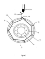
- the device 1 is wider than the wheel 2 so that the latter is well maintained at its flanks, as illustrated by the figure 3 .
- each link 1a and 1b is located only on one of the sidewalls 7 of the tire 8 and will not encroach on the rim 9 which could interfere with the mounting of the wheel 2 on a hub 10 ( figure 4 ).
- Each link 1a and 1b is therefore applied to a different sidewall of the tire 8.
- the spacing between the attachment means 11 is much smaller than the diameter of the wheel 2 so that the wheel does not pass between the meshes formed by the arrangement of the links 1 and fastening means 11.
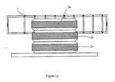
- a pile of wheels 2a, 2b and 2c laid horizontally is made available to the mounting operator, the handling device 1 is positioned to tangent the wheel 2a placed on the top of the stack of wheels.
- the device 1 exceeds in the same proportions the width of the wheel 2a on one side or the other of the latter.
- This first operating mode can be applied to a single wheel directly placed on the ground (configuration not shown). Note that it is possible with the device according to the invention to position each link 1a, 1b substantially facing a sidewall of the tire and thus to fix the device to the wheel without the need to lift. Indeed the device 1 can reach the sidewalls of the wheel 2 without having to lift.
- the wheel 2 is vertical and the handling device 1 is unrolled on the ground.
- the operator To bring the wheel 2 into the configuration shown on the figure 1b , the operator must roll the wheel 2 on the device 1 in the longitudinal direction 27 of the device 1 and to the center thereof.
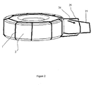
- the figure 2 shows how to make the device integral with the wheel once it is positioned on the wheel.
- the device 1 is thus wound around the wheel 2. For this, the two ends 25 and 26 are brought closer to one another so as to encircle the wheel 2.
- a first end 25 forming a loop of the device 1 is passed in the loop formed by a second end 26 of the device 1.
- the loops are not the same size, it is the largest that is introduced in the smallest.
- the two ends 25 and 26 can simply be edged edges and thus maintained by the establishment of a hoist hook.
- the wheel is trapped over its entire perimeter by the device 1.
- a hook 4 hoisting a handling bridge (bridge not shown) is hooked to the first end 25 of the device. According to the procedure mentioned above (not shown), the two ends 25 and 26 will be placed side by side and will be hooked together with the hook 4. Once hooking done, the assembly formed by the wheel 2 in the device 1 is hoisted and moved.
- the wheel 2 is contained in the wheel handling device 1.
- the device 1 is hooked to a "C" handling 3 itself attached to a crane hook 4.
- the wheel is positioned on a hub 10 of a vehicle 5 resting on candles 6.
- the "C” handling is a well-known tool in the form of a letter C and having a lateral amount 3b offset from the line connecting the attachment point 32 of the load and the point of attachment of the crane hook 4. This tool is only used to allow access to the areas of the vehicle 5 placed in offset.
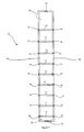
- the device consists of links formed by a first closed chain forming a single loop 20 arranged to make an oblong shape.
- the device 1 comprises a second chain 30 which connects alternately the two longest sides 20a and 20b of the loop 20 so as to form segments constituting fastening means connecting the two sides 20a and 20b of the loop 20.
- each segment (attachment means) of the second chain 30 is chosen so that the longest sides 20a and 20b of the loop 20 are parallel to each other and spaced a distance greater than the width of the the wheel 2 and less than the width of the tire 33 increased by that of the lateral flanks 8.
- the two chains 20 and 30 are made integral at each intersection of the loop 20 and the second chain 30 by means of quick links or by the passage of the second chain 30 in the links of the loop 20. In the latter case the size of the links of the second chain 30 must be small enough to pass in the links of the loop 20.
- the figure 7 shows another embodiment in which the device 1 comprises only two attachment means 11 separated by a distance D equivalent to about one third of the perimeter (2 ⁇ R) of the wheel 2 so that the wheel 2 (of radius R) not pass between the fastening means 11 or it can roll outside the device 1.
- the attachment means 11 are also placed at the same distance from the attachment point 31 of the device 1 with the hook 4 to ensure the pendulum stability of the assembly.
- the flexible links 1a and 1b (1b not shown) provide lateral support of the wheel 2.
Landscapes
- Engineering & Computer Science (AREA)
- Mechanical Engineering (AREA)
- Load-Engaging Elements For Cranes (AREA)
- Automobile Manufacture Line, Endless Track Vehicle, Trailer (AREA)
Claims (9)
- Verfahren zur Handhabung eines Rades (2) mit sehr großer Masse ausgehend von einer Lagerposition, insbesondere um dessen Montage auf eine Nabe (10) eines Fahrzeuges (5) zu ermöglichen, dadurch gekennzeichnet, dass es die folgenden Schritte umfasst:- Positionieren einer Handhabungseinrichtung (1) auf dem Rad (2), welche wenigstens zwei biegsame, nicht elastische Bänder (1a, 1b), die parallel zueinander verlaufen und mit wenigstens zwei biegsamen und nicht elastischen Befestigungsmitteln (11) verbunden sind, umfasst, wobei die Bänder (1a, 1b) und die Befestigungen (11) es ermöglichen, die Reifenlauffläche (2a) eines auf dem Rad (2) montierten Reifens (33) um im Wesentlichen 360° zu umwickeln, wobei sich ein Band so jeweils im Bereich jeder seitlichen Flanke (8) des Rades (2) befindet,- Zusammenführen der Enden (25, 26) der verschiedenen biegsamen Bänder (1a, 1b) derartig, dass das Rad in der Handhabungsvorrichtung (1) festgesetzt wird,- Anhängen der Enden (25, 26) der verschiedenen biegsamen Bänder (1a, 1b) der Handhabungsvorrichtung (1) an eine Hebe- und Handhabungseinrichtung (4), wie eine mit einer fahrbaren Brücke fest verbundenen Winde, wobei diese Letztere das Anheben und das Verfahren des Rades (2) gewährleistet.
- Handhabungsverfahren nach Anspruch 1, dadurch gekennzeichnet, dass für ein Rad (2) in im Wesentlichen senkrechter Lagerposition das Rad (2) auf der Handhabungsvorrichtung (1) durch Rollen positioniert wird, bis es über die Länge und Breite der Handhabungsvorrichtung (1) zentriert ist.
- Handhabungsverfahren nach Anspruch 1, dadurch gekennzeichnet, dass die beiden Bänder (1a, 1b) über ihre Enden fest miteinander verbunden sind und so eine einzige, geschlossene Schleife bilden, und dass die Enden (25, 26) der verschiedenen Bänder (1a, 1b) verbunden werden, indem ein erstes Ende (25) der Schleife durch ein zweites Ende (26) der Schleife durchgeführt wird, wobei das erste Ende (25) der Schleife nun an die Hebeeinrichtung (4) angehängt werden kann.
- Vorrichtung zur Handhabung eines Fahrzeugrades (2), welches mit einem Reifen (33) versehen ist, und welche die Durchführung des Verfahrens nach den vorhergehenden Ansprüchen ermöglicht, insbesondere um die Befestigung des Rades (2) an einer Nabe (10) eines Fahrzeugs (5) zu ermöglichen, dadurch gekennzeichnet, dass sie wenigstens zwei biegsame, nicht elastische Bänder (1a, 1b) umfasst, die parallel zueinander angeordnet sind und eine im Wesentlichen gleiche Länge besitzen, welche größer als der Umfang des Rades (2) ist, wobei die Bänder (1a, 1b) über wenigstens zwei biegsame und nicht elastische Befestigungsmittel (11) miteinander verbunden sind, welche entlang der Bänder (1a, 1b) verteilt sind, wobei die Befestigungsmittel (11) außerdem eine derartige Länge besitzen, dass sie einen Abstand zwischen den biegsamen Bändern (1a, 1b) lassen, welcher größer als die Breite des Reifens (33) und kleiner als die Breite des Reifens (33) ist, welche um die Breite der seitlichen Flanken (8) dieses Letzteren erhöht ist, wobei dadurch ermöglicht wird, ein Band im Bereich jeder seitlichen Flanke (8) des Reifens (33) zu positionieren.
- Handhabungsvorrichtung nach Anspruch 4, dadurch gekennzeichnet, dass die beiden Bänder (1a, 1b) über ihre Enden (25, 26) fest miteinander verbunden sind und so eine einzige, geschlossene Schleife bilden.
- Handhabungsvorrichtung nach Anspruch 5, dadurch gekennzeichnet, dass die biegsamen Bänder (1a, 1b) eine derartige Länge aufweisen, dass es möglich ist, ein Ende (25) der Schleife in das andere Ende (26) einzuführen, nachdem die Vorrichtung (1) auf einem Rad (2) angeordnet wurde.
- Handhabungsvorrichtung nach einem der Ansprüche 4 bis 6, dadurch gekennzeichnet, dass die biegsamen Befestigungsmittel (11) gleichmäßig über den Umfang des Rades (2) verteilt sind und 6 an der Zahl sind.
- Handhabungsvorrichtung nach einem der Ansprüche 4 bis 6, dadurch gekennzeichnet, dass sie wenigstens zwei Befestigungsmittel umfasst, die in etwa 2πR/3 voneinander entfernt und im gleichen Abstand zu den Enden (25, 26) der Vorrichtung angeordnet sind.
- Handhabungsvorrichtung nach einem der Ansprüche 4 bis 8, dadurch gekennzeichnet, dass die biegsamen, nicht elastischen Bänder (1a, 1b) Ketten umfassen.
Applications Claiming Priority (1)
| Application Number | Priority Date | Filing Date | Title |
|---|---|---|---|
| FR1000736A FR2956635B1 (fr) | 2010-02-23 | 2010-02-23 | Dispositif de manutention d'une roue de vehicule et procede de manutention de roue mettant en oeuvre un tel dispositif |
Publications (3)
| Publication Number | Publication Date |
|---|---|
| EP2360030A2 EP2360030A2 (de) | 2011-08-24 |
| EP2360030A3 EP2360030A3 (de) | 2012-07-04 |
| EP2360030B1 true EP2360030B1 (de) | 2014-04-16 |
Family
ID=42617502
Family Applications (1)
| Application Number | Title | Priority Date | Filing Date |
|---|---|---|---|
| EP11290077.4A Active EP2360030B1 (de) | 2010-02-23 | 2011-02-09 | Vorrichtung zur Wartung eines Fahrzeugrads, und Reifenwartungsverfahren, bei dem eine solche Vorrichtung zu Einsatz kommt |
Country Status (4)
| Country | Link |
|---|---|
| US (1) | US8733809B2 (de) |
| EP (1) | EP2360030B1 (de) |
| CA (1) | CA2732586C (de) |
| FR (1) | FR2956635B1 (de) |
Families Citing this family (4)
| Publication number | Priority date | Publication date | Assignee | Title |
|---|---|---|---|---|
| CN106183626B (zh) * | 2016-09-13 | 2019-03-26 | 江苏蒎圣屋工业科技有限公司 | 轮毂拆解机组 |
| JP6693982B2 (ja) * | 2018-02-23 | 2020-05-13 | ファナック株式会社 | 物体の輸送に用いられる輸送具 |
| FR3101574B1 (fr) | 2019-10-03 | 2022-04-22 | Nexter Systems | Dispositif de manutention de roue et procede utilisant un tel dispositif |
| CN115258904B (zh) * | 2022-08-16 | 2026-03-20 | 哈尔滨职业技术大学 | 一种汽车轮毂吊装机构组合平台 |
Family Cites Families (21)
| Publication number | Priority date | Publication date | Assignee | Title |
|---|---|---|---|---|
| US1151389A (en) * | 1915-06-28 | 1915-08-24 | William H Preston | Tractable means for vehicles. |
| US1342753A (en) * | 1919-04-02 | 1920-06-08 | Robert T Ash | Non-skid device |
| US2332113A (en) * | 1941-11-26 | 1943-10-19 | Jesse O Reed | Antiskid tire chain |
| GB766477A (en) * | 1954-08-18 | 1957-01-23 | Thomas Joseph Southall | Carrier device for facilitating the attachment and removal of the wheel of a motor vehicle |
| DE2133801C2 (de) * | 1971-07-07 | 1982-05-13 | Eisen-und Drahtwerk Erlau AG, 7080 Aalen | Reifenkette |
| US3973343A (en) * | 1972-09-20 | 1976-08-10 | Tolfsen Miriam O | Picture frame having a picture mount |
| US3937343A (en) * | 1973-11-09 | 1976-02-10 | Reynold Spulak | Adjustable tire cart |
| US4185674A (en) * | 1978-05-31 | 1980-01-29 | Giannone Victor Salvatore | Vehicle tire chain structure |
| CH641732A5 (de) * | 1979-11-06 | 1984-03-15 | Sulzer Ag | Netz- oder kettenartige gleitschutzvorrichtung fuer fahrzeugraeder. |
| JPH0316813A (ja) * | 1989-06-14 | 1991-01-24 | Kaameito:Kk | 自動車用タイヤ滑り止め装置 |
| DE4000915A1 (de) * | 1989-09-06 | 1991-03-07 | Bernd Hofmann | Anschlaggeraet und hebevorrichtung insbesondere fuer kraftfahrzeuge |
| US5221380A (en) * | 1991-12-16 | 1993-06-22 | Wilson Delbert M | Tire chain installation support |
| CN2181491Y (zh) * | 1992-11-18 | 1994-11-02 | 中国人民解放军驻上海港务局军代表办事处 | 绳索式车轮吊具 |
| GB9421299D0 (en) * | 1994-10-22 | 1994-12-07 | Wcwha David | Vehicle wheel handling device |
| US6047754A (en) * | 1997-08-27 | 2000-04-11 | Drum; Don M. | Device for mounting snow chains on tires |
| US6026876A (en) * | 1998-03-25 | 2000-02-22 | Snyder; Frank L. | Tire traction enhancement system |
| US20020105199A1 (en) * | 2001-02-07 | 2002-08-08 | Thomas Formanek | Tire manipulating apparatus |
| US7070059B1 (en) * | 2003-03-10 | 2006-07-04 | Electric Mobility Corporation | Portable hoist for vehicle |
| US7204282B2 (en) * | 2003-11-04 | 2007-04-17 | Burns Bros., Inc. | System for modular tire chain structure |
| US7845895B2 (en) * | 2007-08-14 | 2010-12-07 | Ibis Tek, Llc | Spare tire carrier with integrated truck jack and spare tire lift |
| US20120048897A1 (en) * | 2010-08-30 | 2012-03-01 | James Hugh Fowler | Spare tire lift assist apparatus |
-
2010
- 2010-02-23 FR FR1000736A patent/FR2956635B1/fr not_active Expired - Fee Related
-
2011
- 2011-02-09 EP EP11290077.4A patent/EP2360030B1/de active Active
- 2011-02-14 US US13/026,846 patent/US8733809B2/en active Active
- 2011-02-22 CA CA2732586A patent/CA2732586C/fr active Active
Also Published As
| Publication number | Publication date |
|---|---|
| EP2360030A2 (de) | 2011-08-24 |
| FR2956635A1 (fr) | 2011-08-26 |
| CA2732586A1 (fr) | 2011-08-23 |
| FR2956635B1 (fr) | 2012-02-10 |
| CA2732586C (fr) | 2016-05-31 |
| US20110206495A1 (en) | 2011-08-25 |
| US8733809B2 (en) | 2014-05-27 |
| EP2360030A3 (de) | 2012-07-04 |
Similar Documents
| Publication | Publication Date | Title |
|---|---|---|
| EP2544938B1 (de) | Entfernbare stützende querträger mit einem in der höhe anpassbaren fünften rad zum stützen eines sattelaufliegers während dessen beladung, zugtransport und entladung | |
| CA2732586C (fr) | Dispositif de manutention d'une roue de vehicule et procede de manutention de roue mettant en oeuvre un tel dispositif | |
| WO2015128594A1 (fr) | Unité robotique de transport de charges longues | |
| FR2774639A1 (fr) | Dispositif, appareil et procede pour permettre a un vehicule de prendre ou de poser au sol une charge presentant un moyen de prehension a l'avant | |
| EP3473581A1 (de) | Förderverfahren einer last, insbesondere einer blechrolle, fördervorrichtung, die die umsetzung dieses verfahrens ermöglicht, und hubgerät, das mit einer solchen vorrichtung ausgestattet ist | |
| WO2013054012A1 (fr) | Appareil de remorquage de vehicule automobile | |
| FR2929919A1 (fr) | Procede de retournement d'une structure et outillage associe a un tel procede. | |
| FR2600954A1 (fr) | Appareil de manutention de charges allongees, telles que des echelles sur le toit d'un vehicule | |
| FR2492747A1 (fr) | Appareil transbordeur de charge a bras porteur | |
| BE1028110B1 (fr) | Un wagonnet de queue serre-câble pour véhicule de traction continue de câble sans fin et son procédé d'utilisation | |
| FR2545468A1 (fr) | Dispositif de montage de fourche sur un chariot elevateur a fourche et procede de dechargement employant un chariot elevateur a fourche comportant un tel dispositif | |
| CA2890453A1 (fr) | Machine et procede pour l'extraction des bourrelets d'un pneumatique en fin de vie | |
| WO2021079219A1 (fr) | Grue à flèche télescopique et procédé de manutention d'une charge à l'aide d'une telle grue | |
| FR2979335A1 (fr) | Dispositif pour manipuler un objet allonge, en particulier un module de filtration membranaire, et procede de manipulation mettant en oeuvre ce dispositif | |
| EP4037918B1 (de) | Radhandhabungsvorrichtung und verfahren mit einer solchen vorrichtung | |
| FR2973020A1 (fr) | Dispositif de manutention de bennes | |
| WO2020201570A1 (fr) | Connecteur, fausse fourche largable muni d'un tel connecteur et procédé d'utilisation | |
| EP2123587A1 (de) | Vorrichtung zum Anheben und Transportieren eines Fasses, das Spulen mit Schweissdraht enthält | |
| EP1132330A1 (de) | Vorrichtung zum Laden von Spulen auf ein Regal | |
| FR3078856A1 (fr) | Remorque porte-regimes bananes pendulaires surbaissee | |
| FR3050728A1 (fr) | Palonnier de levage avec support sous anneaux a elingues | |
| FR2888826A1 (fr) | Systeme de securite pour levage big-bag | |
| FR3014368A1 (fr) | Roues cages pieuvres, avec une conception de fixation rapide en jumelage, pour vehicules legers 4x4, sans modification des vehicules, utilisees pour le franchissement de terrains ultras boueux | |
| FR3129669A1 (fr) | Dispositif d’accrochage compact et automatique, à actionnement gravitaire, pour la manutention de conteneurs. | |
| FR3154960A1 (fr) | Dispositif mobile de transport de charge à système de maintien simplifié |
Legal Events
| Date | Code | Title | Description |
|---|---|---|---|
| PUAI | Public reference made under article 153(3) epc to a published international application that has entered the european phase |
Free format text: ORIGINAL CODE: 0009012 |
|
| AK | Designated contracting states |
Kind code of ref document: A2 Designated state(s): AL AT BE BG CH CY CZ DE DK EE ES FI FR GB GR HR HU IE IS IT LI LT LU LV MC MK MT NL NO PL PT RO RS SE SI SK SM TR |
|
| AX | Request for extension of the european patent |
Extension state: BA ME |
|
| PUAL | Search report despatched |
Free format text: ORIGINAL CODE: 0009013 |
|
| AK | Designated contracting states |
Kind code of ref document: A3 Designated state(s): AL AT BE BG CH CY CZ DE DK EE ES FI FR GB GR HR HU IE IS IT LI LT LU LV MC MK MT NL NO PL PT RO RS SE SI SK SM TR |
|
| AX | Request for extension of the european patent |
Extension state: BA ME |
|
| RIC1 | Information provided on ipc code assigned before grant |
Ipc: B60B 29/00 20060101AFI20120525BHEP Ipc: B66C 1/24 20060101ALI20120525BHEP Ipc: B66C 1/12 20060101ALI20120525BHEP |
|
| 17P | Request for examination filed |
Effective date: 20121227 |
|
| RIC1 | Information provided on ipc code assigned before grant |
Ipc: B66C 1/12 20060101ALI20130628BHEP Ipc: B66C 1/24 20060101ALI20130628BHEP Ipc: B60B 29/00 20060101AFI20130628BHEP |
|
| GRAP | Despatch of communication of intention to grant a patent |
Free format text: ORIGINAL CODE: EPIDOSNIGR1 |
|
| INTG | Intention to grant announced |
Effective date: 20130823 |
|
| GRAS | Grant fee paid |
Free format text: ORIGINAL CODE: EPIDOSNIGR3 |
|
| GRAA | (expected) grant |
Free format text: ORIGINAL CODE: 0009210 |
|
| AK | Designated contracting states |
Kind code of ref document: B1 Designated state(s): AL AT BE BG CH CY CZ DE DK EE ES FI FR GB GR HR HU IE IS IT LI LT LU LV MC MK MT NL NO PL PT RO RS SE SI SK SM TR |
|
| REG | Reference to a national code |
Ref country code: GB Ref legal event code: FG4D Free format text: NOT ENGLISH |
|
| REG | Reference to a national code |
Ref country code: CH Ref legal event code: EP |
|
| REG | Reference to a national code |
Ref country code: AT Ref legal event code: REF Ref document number: 662279 Country of ref document: AT Kind code of ref document: T Effective date: 20140515 |
|
| REG | Reference to a national code |
Ref country code: IE Ref legal event code: FG4D Free format text: LANGUAGE OF EP DOCUMENT: FRENCH |
|
| REG | Reference to a national code |
Ref country code: DE Ref legal event code: R096 Ref document number: 602011006183 Country of ref document: DE Effective date: 20140522 |
|
| REG | Reference to a national code |
Ref country code: SE Ref legal event code: TRGR |
|
| REG | Reference to a national code |
Ref country code: AT Ref legal event code: MK05 Ref document number: 662279 Country of ref document: AT Kind code of ref document: T Effective date: 20140416 |
|
| REG | Reference to a national code |
Ref country code: NL Ref legal event code: VDEP Effective date: 20140416 |
|
| REG | Reference to a national code |
Ref country code: LT Ref legal event code: MG4D |
|
| PG25 | Lapsed in a contracting state [announced via postgrant information from national office to epo] |
Ref country code: NO Free format text: LAPSE BECAUSE OF FAILURE TO SUBMIT A TRANSLATION OF THE DESCRIPTION OR TO PAY THE FEE WITHIN THE PRESCRIBED TIME-LIMIT Effective date: 20140716 Ref country code: IS Free format text: LAPSE BECAUSE OF FAILURE TO SUBMIT A TRANSLATION OF THE DESCRIPTION OR TO PAY THE FEE WITHIN THE PRESCRIBED TIME-LIMIT Effective date: 20140816 Ref country code: LT Free format text: LAPSE BECAUSE OF FAILURE TO SUBMIT A TRANSLATION OF THE DESCRIPTION OR TO PAY THE FEE WITHIN THE PRESCRIBED TIME-LIMIT Effective date: 20140416 Ref country code: BG Free format text: LAPSE BECAUSE OF FAILURE TO SUBMIT A TRANSLATION OF THE DESCRIPTION OR TO PAY THE FEE WITHIN THE PRESCRIBED TIME-LIMIT Effective date: 20140716 Ref country code: CY Free format text: LAPSE BECAUSE OF FAILURE TO SUBMIT A TRANSLATION OF THE DESCRIPTION OR TO PAY THE FEE WITHIN THE PRESCRIBED TIME-LIMIT Effective date: 20140416 Ref country code: NL Free format text: LAPSE BECAUSE OF FAILURE TO SUBMIT A TRANSLATION OF THE DESCRIPTION OR TO PAY THE FEE WITHIN THE PRESCRIBED TIME-LIMIT Effective date: 20140416 Ref country code: GR Free format text: LAPSE BECAUSE OF FAILURE TO SUBMIT A TRANSLATION OF THE DESCRIPTION OR TO PAY THE FEE WITHIN THE PRESCRIBED TIME-LIMIT Effective date: 20140717 |
|
| PG25 | Lapsed in a contracting state [announced via postgrant information from national office to epo] |
Ref country code: LV Free format text: LAPSE BECAUSE OF FAILURE TO SUBMIT A TRANSLATION OF THE DESCRIPTION OR TO PAY THE FEE WITHIN THE PRESCRIBED TIME-LIMIT Effective date: 20140416 Ref country code: PL Free format text: LAPSE BECAUSE OF FAILURE TO SUBMIT A TRANSLATION OF THE DESCRIPTION OR TO PAY THE FEE WITHIN THE PRESCRIBED TIME-LIMIT Effective date: 20140416 Ref country code: HR Free format text: LAPSE BECAUSE OF FAILURE TO SUBMIT A TRANSLATION OF THE DESCRIPTION OR TO PAY THE FEE WITHIN THE PRESCRIBED TIME-LIMIT Effective date: 20140416 Ref country code: ES Free format text: LAPSE BECAUSE OF FAILURE TO SUBMIT A TRANSLATION OF THE DESCRIPTION OR TO PAY THE FEE WITHIN THE PRESCRIBED TIME-LIMIT Effective date: 20140416 Ref country code: AT Free format text: LAPSE BECAUSE OF FAILURE TO SUBMIT A TRANSLATION OF THE DESCRIPTION OR TO PAY THE FEE WITHIN THE PRESCRIBED TIME-LIMIT Effective date: 20140416 Ref country code: RS Free format text: LAPSE BECAUSE OF FAILURE TO SUBMIT A TRANSLATION OF THE DESCRIPTION OR TO PAY THE FEE WITHIN THE PRESCRIBED TIME-LIMIT Effective date: 20140416 |
|
| PG25 | Lapsed in a contracting state [announced via postgrant information from national office to epo] |
Ref country code: PT Free format text: LAPSE BECAUSE OF FAILURE TO SUBMIT A TRANSLATION OF THE DESCRIPTION OR TO PAY THE FEE WITHIN THE PRESCRIBED TIME-LIMIT Effective date: 20140818 |
|
| REG | Reference to a national code |
Ref country code: DE Ref legal event code: R097 Ref document number: 602011006183 Country of ref document: DE |
|
| PG25 | Lapsed in a contracting state [announced via postgrant information from national office to epo] |
Ref country code: RO Free format text: LAPSE BECAUSE OF FAILURE TO SUBMIT A TRANSLATION OF THE DESCRIPTION OR TO PAY THE FEE WITHIN THE PRESCRIBED TIME-LIMIT Effective date: 20140416 Ref country code: SK Free format text: LAPSE BECAUSE OF FAILURE TO SUBMIT A TRANSLATION OF THE DESCRIPTION OR TO PAY THE FEE WITHIN THE PRESCRIBED TIME-LIMIT Effective date: 20140416 Ref country code: CZ Free format text: LAPSE BECAUSE OF FAILURE TO SUBMIT A TRANSLATION OF THE DESCRIPTION OR TO PAY THE FEE WITHIN THE PRESCRIBED TIME-LIMIT Effective date: 20140416 Ref country code: DK Free format text: LAPSE BECAUSE OF FAILURE TO SUBMIT A TRANSLATION OF THE DESCRIPTION OR TO PAY THE FEE WITHIN THE PRESCRIBED TIME-LIMIT Effective date: 20140416 Ref country code: EE Free format text: LAPSE BECAUSE OF FAILURE TO SUBMIT A TRANSLATION OF THE DESCRIPTION OR TO PAY THE FEE WITHIN THE PRESCRIBED TIME-LIMIT Effective date: 20140416 |
|
| PLBE | No opposition filed within time limit |
Free format text: ORIGINAL CODE: 0009261 |
|
| STAA | Information on the status of an ep patent application or granted ep patent |
Free format text: STATUS: NO OPPOSITION FILED WITHIN TIME LIMIT |
|
| 26N | No opposition filed |
Effective date: 20150119 |
|
| REG | Reference to a national code |
Ref country code: DE Ref legal event code: R097 Ref document number: 602011006183 Country of ref document: DE Effective date: 20150119 |
|
| PG25 | Lapsed in a contracting state [announced via postgrant information from national office to epo] |
Ref country code: BE Free format text: LAPSE BECAUSE OF NON-PAYMENT OF DUE FEES Effective date: 20150228 |
|
| PG25 | Lapsed in a contracting state [announced via postgrant information from national office to epo] |
Ref country code: SI Free format text: LAPSE BECAUSE OF FAILURE TO SUBMIT A TRANSLATION OF THE DESCRIPTION OR TO PAY THE FEE WITHIN THE PRESCRIBED TIME-LIMIT Effective date: 20140416 |
|
| PG25 | Lapsed in a contracting state [announced via postgrant information from national office to epo] |
Ref country code: LU Free format text: LAPSE BECAUSE OF FAILURE TO SUBMIT A TRANSLATION OF THE DESCRIPTION OR TO PAY THE FEE WITHIN THE PRESCRIBED TIME-LIMIT Effective date: 20150209 |
|
| PG25 | Lapsed in a contracting state [announced via postgrant information from national office to epo] |
Ref country code: MC Free format text: LAPSE BECAUSE OF FAILURE TO SUBMIT A TRANSLATION OF THE DESCRIPTION OR TO PAY THE FEE WITHIN THE PRESCRIBED TIME-LIMIT Effective date: 20140416 |
|
| REG | Reference to a national code |
Ref country code: IE Ref legal event code: MM4A |
|
| REG | Reference to a national code |
Ref country code: FR Ref legal event code: PLFP Year of fee payment: 6 |
|
| PG25 | Lapsed in a contracting state [announced via postgrant information from national office to epo] |
Ref country code: IE Free format text: LAPSE BECAUSE OF NON-PAYMENT OF DUE FEES Effective date: 20150209 |
|
| PG25 | Lapsed in a contracting state [announced via postgrant information from national office to epo] |
Ref country code: MT Free format text: LAPSE BECAUSE OF FAILURE TO SUBMIT A TRANSLATION OF THE DESCRIPTION OR TO PAY THE FEE WITHIN THE PRESCRIBED TIME-LIMIT Effective date: 20140416 |
|
| REG | Reference to a national code |
Ref country code: FR Ref legal event code: PLFP Year of fee payment: 7 |
|
| PG25 | Lapsed in a contracting state [announced via postgrant information from national office to epo] |
Ref country code: HU Free format text: LAPSE BECAUSE OF FAILURE TO SUBMIT A TRANSLATION OF THE DESCRIPTION OR TO PAY THE FEE WITHIN THE PRESCRIBED TIME-LIMIT; INVALID AB INITIO Effective date: 20110209 Ref country code: SM Free format text: LAPSE BECAUSE OF FAILURE TO SUBMIT A TRANSLATION OF THE DESCRIPTION OR TO PAY THE FEE WITHIN THE PRESCRIBED TIME-LIMIT Effective date: 20140416 |
|
| PG25 | Lapsed in a contracting state [announced via postgrant information from national office to epo] |
Ref country code: TR Free format text: LAPSE BECAUSE OF FAILURE TO SUBMIT A TRANSLATION OF THE DESCRIPTION OR TO PAY THE FEE WITHIN THE PRESCRIBED TIME-LIMIT Effective date: 20140416 |
|
| REG | Reference to a national code |
Ref country code: FR Ref legal event code: PLFP Year of fee payment: 8 |
|
| PG25 | Lapsed in a contracting state [announced via postgrant information from national office to epo] |
Ref country code: MK Free format text: LAPSE BECAUSE OF FAILURE TO SUBMIT A TRANSLATION OF THE DESCRIPTION OR TO PAY THE FEE WITHIN THE PRESCRIBED TIME-LIMIT Effective date: 20140416 |
|
| PG25 | Lapsed in a contracting state [announced via postgrant information from national office to epo] |
Ref country code: AL Free format text: LAPSE BECAUSE OF FAILURE TO SUBMIT A TRANSLATION OF THE DESCRIPTION OR TO PAY THE FEE WITHIN THE PRESCRIBED TIME-LIMIT Effective date: 20140416 |
|
| REG | Reference to a national code |
Ref country code: CH Ref legal event code: U11 Free format text: ST27 STATUS EVENT CODE: U-0-0-U10-U11 (AS PROVIDED BY THE NATIONAL OFFICE) Effective date: 20260301 |
|
| PGFP | Annual fee paid to national office [announced via postgrant information from national office to epo] |
Ref country code: SE Payment date: 20260121 Year of fee payment: 16 |
|
| PGFP | Annual fee paid to national office [announced via postgrant information from national office to epo] |
Ref country code: GB Payment date: 20260122 Year of fee payment: 16 |
|
| PGFP | Annual fee paid to national office [announced via postgrant information from national office to epo] |
Ref country code: DE Payment date: 20260121 Year of fee payment: 16 |
|
| PGFP | Annual fee paid to national office [announced via postgrant information from national office to epo] |
Ref country code: FI Payment date: 20260121 Year of fee payment: 16 Ref country code: IT Payment date: 20260121 Year of fee payment: 16 |
|
| PGFP | Annual fee paid to national office [announced via postgrant information from national office to epo] |
Ref country code: FR Payment date: 20260121 Year of fee payment: 16 |
|
| PGFP | Annual fee paid to national office [announced via postgrant information from national office to epo] |
Ref country code: CH Payment date: 20260301 Year of fee payment: 16 |